EP2442410A1 - Electrical connector - Google Patents
Electrical connector Download PDFInfo
- Publication number
- EP2442410A1 EP2442410A1 EP11177329A EP11177329A EP2442410A1 EP 2442410 A1 EP2442410 A1 EP 2442410A1 EP 11177329 A EP11177329 A EP 11177329A EP 11177329 A EP11177329 A EP 11177329A EP 2442410 A1 EP2442410 A1 EP 2442410A1
- Authority
- EP
- European Patent Office
- Prior art keywords
- mating surface
- stepped
- base
- extending
- insulating body
- Prior art date
- Legal status (The legal status is an assumption and is not a legal conclusion. Google has not performed a legal analysis and makes no representation as to the accuracy of the status listed.)
- Granted
Links
Images



Classifications
-
- H—ELECTRICITY
- H01—ELECTRIC ELEMENTS
- H01R—ELECTRICALLY-CONDUCTIVE CONNECTIONS; STRUCTURAL ASSOCIATIONS OF A PLURALITY OF MUTUALLY-INSULATED ELECTRICAL CONNECTING ELEMENTS; COUPLING DEVICES; CURRENT COLLECTORS
- H01R13/00—Details of coupling devices of the kinds covered by groups H01R12/70 or H01R24/00 - H01R33/00
- H01R13/64—Means for preventing incorrect coupling
- H01R13/642—Means for preventing incorrect coupling by position or shape of contact members
-
- H—ELECTRICITY
- H01—ELECTRIC ELEMENTS
- H01R—ELECTRICALLY-CONDUCTIVE CONNECTIONS; STRUCTURAL ASSOCIATIONS OF A PLURALITY OF MUTUALLY-INSULATED ELECTRICAL CONNECTING ELEMENTS; COUPLING DEVICES; CURRENT COLLECTORS
- H01R13/00—Details of coupling devices of the kinds covered by groups H01R12/70 or H01R24/00 - H01R33/00
- H01R13/46—Bases; Cases
- H01R13/52—Dustproof, splashproof, drip-proof, waterproof, or flameproof cases
- H01R13/5219—Sealing means between coupling parts, e.g. interfacial seal
-
- H—ELECTRICITY
- H01—ELECTRIC ELEMENTS
- H01R—ELECTRICALLY-CONDUCTIVE CONNECTIONS; STRUCTURAL ASSOCIATIONS OF A PLURALITY OF MUTUALLY-INSULATED ELECTRICAL CONNECTING ELEMENTS; COUPLING DEVICES; CURRENT COLLECTORS
- H01R2201/00—Connectors or connections adapted for particular applications
- H01R2201/26—Connectors or connections adapted for particular applications for vehicles
Definitions
- the present invention relates to electrical connectors, and in particular, to compact electrical connectors.
- Certain complex systems such as a gas turbine engine, include both mechanical subsystems and electrical subsystems.
- Certain mechanical subsystems can be subjected to relatively large forces, and therefore require relatively strong components.
- the electrical subsystems typically require an electrical connection for power transmission, signal transmission, or both.
- a male electrical connector includes an electrically insulating body having a base mating surface and a first stepped mating surface offset from the base mating surface.
- a first electrically conducting pin extends from the base mating surface.
- a second electrically conducting pin extends from the first stepped mating surface.
- Another embodiment of the present invention is a female electrical connector that includes an electrically insulating body having a base mating surface and a first stepped mating surface offset from the base mating surface.
- a first electrically conducting socket extends from an interior portion of the electrically insulating body to the base mating surface.
- a second electrically conducting socket extends from the interior portion of the electrically insulating body to the first stepped mating surface.
- FIG. 1 is a schematic perspective partially cut-away exploded view of a connection assembly.
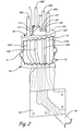
- FIG. 2 is a schematic perspective partially cut-away view of a male connector used in the connection assembly of FIG. 1 .
- FIG. 3 is a schematic perspective partially cut-away view of a female connector used in the connection assembly of FIG 1 .
- FIG. 3A is an enlarged schematic perspective view of the female connector of FIG. 3 .
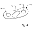
- FIG. 4 is a schematic perspective view of an interfacial seal for positioning between the male connector of FIG. 2 and the female connector of FIG. 3 .
- FIG. 1 is a schematic perspective exploded view of connection assembly 10.
- Connection assembly 10 includes fan inlet variable vane (FIVV) 12, vane arm 14, bushing 16, washer 18, hinge pin 20, tab washer 22, male connector 24, and female connector 26.
- FIVV 12 is a rotatable vane positioned at an inlet of a gas turbine engine (not shown). As FIVV 12 rotates, FIVV 12 can increase or decrease the amount of air entering at the inlet of the gas turbine engine.
- FIVV 12 includes metal spar 27 covered by composite layers 28.
- Metal spar 27 provides structural support for FIVV 12, and includes spar blade 29 and shaft 30.
- Composite layers 28 can include multiple layers which cover spar blade 29 and extend past trailing edge 29A of spar blade 29. In FIG. 1 , composite layers 28 have been partially cut-away to show details within.
- Shaft 30 has a substantially cylindrical perimeter 32 and a substantially circular shaft end 34 with teeth 36 extending therefrom.
- Vane arm 14 has arm portion 38 connecting handle pin 40 to shaft 42. Like shaft 30, shaft 42 also has a substantially cylindrical perimeter 44 and a substantially circular shaft end 46 with teeth 48 extending therefrom. Teeth 36 mesh with teeth 48 to couple shafts 30 and 42 together to rotate inside bushing 16 about centerline axis C L .
- Bushing 16 has a substantially cylindrical inner surface 50 and functions to limit wear as shafts 30 and 42 rotate against bushing 16.
- Bushing 16 can be connected to or integrally formed with an engine case (not shown) of the gas turbine engine.
- Handle pin 40 connects to a mechanism (not shown) that drives vane arm 14 to rotate FIVV 12 as directed by a gas turbine engine controller (not shown).
- Hinge pin 20 extends through hole 52 in vane arm 14 and hole 54 in FIVV 12. Hinge pin 20 threadedly engages with FIVV 12 to hold vane arm 14 rotatably fixed with respect to FIVV 12.
- Tab washer 22 has tab 56 which folds into hole 58 of vane arm 14, and also has tab 60 which folds against head 62 of hinge pin 20 to limit rotation of hinge pin 20 caused by vibration or otherwise.
- Connector hole 64 extends through shaft 42 of vane arm 14.
- Connector hole 66 extends through shaft 30 of FIVV 12.
- Connector holes 64 and 66 are defined by their respective inner surfaces 68 and 70. When assembled, connector hole 64 is aligned with connector hole 66 to allow male connector 24 and female connector 26 to connect to one-another by extending through connector holes 64 and 66.
- Male connector 24 has electrically insulating body 72 with outer surface 74
- female connector 26 has electrically insulating body 76 with outer surface 78.
- Inner surface 68, inner surface 70, outer surface 74, and outer surface 78 are each substantially kidney-shaped, with a relatively narrow width W and a relatively long length L (width W and length L are shown with respect to outer surface 78 of electrically insulating body 76 in FIG. 3 for clarity). Because connector holes 64 and 66 have a relatively narrow width W in a direction perpendicular to centerline axis C L , connector holes 64 and 66 have a relatively small impact on the torque strength of shafts 30 and 42. Inner surface 68, inner surface 70, outer surface 74, and outer surface 78 being kidney-shaped also helps ensure male connector 24 and female connector 26 are properly aligned when removably connected to each other. Connector holes 64 and 66 can also be referred to as circular slots, since they are shaped as slots that curve in a circular direction about centerline axis C L .
- O-ring seal 79 extends around outer surface 74 of insulating body 72 to provide a seal against inner surface 70 of connector hole 66.
- Female connector 26 is connected to cable 80, which can connect to a wire harness (not shown), which in turn can connect to an engine controller (not shown).
- Male connector 24 is connected to heater 82 via heater connection pad 84 and also connected to temperature sensor 86.
- Temperature sensor 86 can be a resistance temperature detector (RTD) positioned on FIVV 12 for sensing temperature of FIVV 12. In the illustrated embodiment, temperature sensor 86 is a relatively long and thin RTD positioned between spar blade 29 and composite layers 28.
- Heater 82 is also positioned on FIVV 12 for deicing FIVV 12. In the illustrated embodiment, heater 82 is a thin, flat layer within composite layers 28.
- Male connector 24 has four pins 88 which mate with four sockets 90 to connect the engine controller to heater 82 and temperature sensor 86. The engine controller receives temperature signals from temperature sensor 86 and activates heater 82, as necessary, to deice FIVV 12.
- FIG. 2 is a schematic perspective view of male connector 24.
- Electrically insulating body 72 of male connector 24 has outer surface 74 extending from and substantially perpendicular to base mating surface 100. Outer surface 74 meets base mating surface 100 at perimeter 102 of base mating surface 100, which is substantially kidney-shaped.
- Stepped mating surfaces 104 and 106 are offset from base mating surface 100.
- Stepped mating surface 104 is substantially parallel to and elevated above base mating surface 100.
- Stepped mating surface 106 is substantially parallel to and elevated above both stepped mating surface 104 and base mating surface 100.
- Stepped mating surface 106 is horizontally adjacent to stepped mating surface 104.
- stepped mating surface 106 appears to be adjacent to stepped mating surface 104 when viewed from a position above and normal to stepped mating surfaces 104 and 106, even though stepped mating surface 106 is elevated vertically above stepped mating surface 104.
- Stepped mating surface 104 has curved perimeter edge 108 and straight perimeter edge 110.
- Stepped mating surface 106 has curved perimeter edge 112 and straight perimeter edge 114 horizontally adjacent straight perimeter edge 110.
- Base mating surface 100, stepped mating surface 104, and stepped mating surface 106 will be collectively referred to as male mating surface 116.
- Pins 88A - 88D extend from electrically insulating body 72 in substantially the same direction so as to be substantially parallel to one-another.
- Pins 88A and 88D extend from base mating surface 100.
- Pin 88B extends from stepped mating surface 104.
- Pin 88C extends from stepped mating surface 106.
- Pins 88B and 88C are positioned substantially between pins 88A and 88D.
- Stepped mating surfaces 104 and 106 are also positioned substantially between pins 88A and 88D.
- Pins 88A and 88D have a larger diameter than pins 88B and 88C.
- Pins 88A - 88D are made of electrically conducting material.
- Pins 88A and 88D are electrically connected to heater connection pad 84 via wires 118A and 118D, respectively, for transmitting power to heater 82 (shown in FIG. 1 ).
- Pins 88B and 88C are electrically connected to temperature sensor 86 via wires 118B and 118C, respectively, for transmitting temperature signals from temperature sensor 86.
- Pins 88A and 88D transmit power that is relatively high voltage and high current as compared to the signals transmitted by pins 88B and 88C.
- FIG. 3 is a schematic perspective view of female connector 26.
- Electrically insulating body 76 of female connector 26 has outer surface 78 extending from and substantially perpendicular to base mating surface 120. Outer surface 78 meets base mating surface 120 at perimeter 122 of base mating surface 120, which is substantially kidney-shaped.
- Stepped mating surfaces 124 and 126 are offset from base mating surface 120. Stepped mating surface 124 is substantially parallel to and sunken below base mating surface 120. Stepped mating surface 126 is substantially parallel to and sunken below both stepped mating surface 124 and base mating surface 120. Stepped mating surface 126 is horizontally adjacent to stepped mating surface 124, though sunken vertically lower.
- Stepped mating surface 124 has curved perimeter edge 130 and straight perimeter edge 132.
- Stepped mating surface 126 has curved perimeter edge 134 and straight perimeter edge 136 (shown in FIG. 3A ) horizontally adjacent straight perimeter edge 132.
- Base mating surface 120, stepped mating surface 124, and stepped mating surface 126 will be collectively referred to as female mating surface 128.
- Sockets 90A - 90D are aligned in substantially the same direction so as to be substantially parallel to one-another. Sockets 90A and 90D extend from an interior portion of electrically insulating body 76 to base mating surface 120. Socket 90B extends from an interior portion of electrically insulating body 76 to stepped mating surface 124. Socket 90C extends from an interior portion of electrically insulating body 76 to stepped mating surface 126. Sockets 90B and 90C are positioned substantially between sockets 90A and 90D. Stepped mating surfaces 124 and 126 are also positioned substantially between sockets 90A and 90D. Sockets 90A and 90D have a larger diameter than sockets 90B and 90C. Sockets 90A - 90D are made of electrically conducting material.
- Sockets 90A - 90D are electrically connected to the wire harness (not shown) and ultimately to the engine controller (not shown) via wires 138A - 138D, respectively. Sockets 90A and 90D transmit power that is relatively high voltage and high current as compared to the signals transmitted by sockets 90B and 90C.
- male mating surface 116 can be positioned near female mating surface 128.
- Male mating surface 116 can be substantially adjacent female mating surface 128 or can be spaced from female mating surface 128 by positioning interfacial seal 140 (shown in FIG. 4 ) between base mating surfaces 100 and 120.
- Base mating surface 100 can be positioned near base mating surface 120;
- stepped mating surface 104 can be positioned near stepped mating surface 124; and stepped mating surface 106 can be positioned near stepped mating surface 126.
- Pins 88A - 88D each require sufficient electrical insulation to prevent arcing to nearby conductors, such as each other, spar 27 (shown in FIG. 1 ), or other conducting surfaces.
- sockets 90A - 90D also requires sufficient electrical insulation to prevent arcing to nearby conductors, such as each other.
- wires 118A - 118D and wires 138A - 138D are also required electrical insulation to prevent arcing to nearby conductors, such as each other.
- wires 118A - 118D and wires 138A - 138D Electrically insulating bodies 72 and 76 can provide that insulation to prevent arcing for those portions of pins 88A - 88D, sockets 90A - 90D, wires 118A - 180D, and wires 138A - 138D which electrically insulating bodies 72 and 76 cover.
- pins 88A - 88D extend from electrically insulating body 72 to insert into sockets 90A - 90D.
- pins 88A - 88D are positioned in sockets 90A - 90D.
- exposed portions of pins 88A - 88D are insulated by only air.
- the suitability of air as an electric insulator depends in part on dielectric distance between two conductors. A table of suitable dielectric distances depending on voltage and current can be found in MIL-STD-38999. For ordinary conductors, the distance between exposed portions of two pins would be that of a perpendicular line directly between those pins.
- pin 88D and pin 88C extends along path P, which travels across a portion of base mating surface 100, up to stepped mating surface 106, and across a portion of stepped mating surface 106.
- path P which travels across a portion of base mating surface 100, up to stepped mating surface 106, and across a portion of stepped mating surface 106.
- extending pin 88C from stepped mating surface 106 instead of base mating surface 100 increases the effective distance between pin 88C and pin 88D for electrical insulation purposes.
- extending pin 88B from stepped mating surface 104 instead of base mating surface 100 increases the effective distance between pin 88B and pin 88A for electrical insulation purposes.
- pins 88A and 88D can also extend from a stepped mating surface that is offset from base mating surface 100.
- stepped mating surfaces 104 and 106 Elevating stepped mating surfaces 104 and 106 above base mating surface 100 allows pins 88A - 88D to be horizontally positioned closer together, and allows overall size of male connector 24 to be reduced.
- sinking stepped mating surfaces 124 and 126 below base mating surface 120 allows sockets 90A - 90D to be positioned closer together, and allows overall size of female connector 26 to be reduced. This allows connector holes 64 and 66 to have their sizes reduced, thus increasing strength of shafts 30 and 42.
- stepped mating surfaces 104 and 106 can be sunken below base mating surface 100 and stepped mating surfaces 124 and 126 can be elevated above base mating surface 120.
- FIG. 3A is an enlarged schematic perspective view of female connector 26.
- FIG. 3A is enlarged to show greater detail of stepped mating surfaces 124 and 126, including curved perimeter edge 130, straight perimeter edge 132, curved perimeter edge 134, and straight perimeter edge 136 each shown partially or entirely in phantom.
- FIG. 4 is a schematic perspective view of interfacial seal 140.
- Interfacial seal 140 is a thin silicone gasket that can be positioned between base mating surface 100 (shown in FIG. 2 ) and base mating surface 120 (shown in FIG. 3 ) to reduce exposure of pins 88A - 88D (shown in FIG. 2 ) and sockets 90A - 90D (shown in FIG. 3 ) to moisture.
- Interfacial seal 140 has a substantially similar shape to that of base mating surfaces 100 and 120. Hole 142 aligns with socket 90A to allow pin 88A to pass through interfacial seal 140. Hole 144 aligns with socket 90D to allow pin 88D to pass through interfacial seal 140.
- Hole 146 aligns with curved perimeter edges 108, 112, 130, and 134 (shown in FIGS. 2 and 3 ) to allow pin 88B, pin 88C, stepped mating surface 104, and stepped mating surface 106 (shown in FIGS. 2 and 3 ) to pass through interfacial seal 140.
- male connector 24 and female connector 26 is not limited for use in deicing a fan inlet variable vane. Rather, male connector 24 and female connector 26 can be used with other rotating mechanical couplings or in virtually any application where space is limited but electrical arcing between connector pins is a concern.
Landscapes
- Connector Housings Or Holding Contact Members (AREA)
Abstract
Description
- The present invention relates to electrical connectors, and in particular, to compact electrical connectors. Certain complex systems, such as a gas turbine engine, include both mechanical subsystems and electrical subsystems. Certain mechanical subsystems can be subjected to relatively large forces, and therefore require relatively strong components. The electrical subsystems typically require an electrical connection for power transmission, signal transmission, or both. In gas turbine engines and other systems where space is a premium, it can be difficult to locate cables and electrical connectors in positions suitable to make electrical connections for the electrical subsystems while limiting negative impact on structural strength of components of the mechanical subsystems.
- For example, it may be desirable to drill a hole through a mechanical component in order to run a cable to an electrical subsystem. However, drilling a hole large enough for a standard electrical connector can undesirably reduce strength of the mechanical component below a suitable threshold. The difficulty with using a smaller connector is that if the connector's pins or other contact element get too close together, arcing can occur between the pins, causing equipment to function improperly and/or become damaged.
- According to the present invention, a male electrical connector includes an electrically insulating body having a base mating surface and a first stepped mating surface offset from the base mating surface. A first electrically conducting pin extends from the base mating surface. A second electrically conducting pin extends from the first stepped mating surface.
- Another embodiment of the present invention is a female electrical connector that includes an electrically insulating body having a base mating surface and a first stepped mating surface offset from the base mating surface. A first electrically conducting socket extends from an interior portion of the electrically insulating body to the base mating surface. A second electrically conducting socket extends from the interior portion of the electrically insulating body to the first stepped mating surface.
-
FIG. 1 is a schematic perspective partially cut-away exploded view of a connection assembly. -
FIG. 2 is a schematic perspective partially cut-away view of a male connector used in the connection assembly ofFIG. 1 . -
FIG. 3 is a schematic perspective partially cut-away view of a female connector used in the connection assembly ofFIG 1 . -
FIG. 3A is an enlarged schematic perspective view of the female connector ofFIG. 3 . -
FIG. 4 is a schematic perspective view of an interfacial seal for positioning between the male connector ofFIG. 2 and the female connector ofFIG. 3 . -
FIG. 1 is a schematic perspective exploded view ofconnection assembly 10.Connection assembly 10 includes fan inlet variable vane (FIVV) 12,vane arm 14,bushing 16,washer 18,hinge pin 20,tab washer 22,male connector 24, andfemale connector 26. FIVV 12 is a rotatable vane positioned at an inlet of a gas turbine engine (not shown). AsFIVV 12 rotates,FIVV 12 can increase or decrease the amount of air entering at the inlet of the gas turbine engine. FIVV 12 includesmetal spar 27 covered bycomposite layers 28.Metal spar 27 provides structural support for FIVV 12, and includesspar blade 29 andshaft 30.Composite layers 28 can include multiple layers which coverspar blade 29 and extend pasttrailing edge 29A ofspar blade 29. InFIG. 1 ,composite layers 28 have been partially cut-away to show details within.Shaft 30 has a substantiallycylindrical perimeter 32 and a substantiallycircular shaft end 34 withteeth 36 extending therefrom. - Vane
arm 14 hasarm portion 38 connectinghandle pin 40 toshaft 42. Likeshaft 30,shaft 42 also has a substantiallycylindrical perimeter 44 and a substantiallycircular shaft end 46 withteeth 48 extending therefrom.Teeth 36 mesh withteeth 48 tocouple shafts inner surface 50 and functions to limit wear asshafts Bushing 16 can be connected to or integrally formed with an engine case (not shown) of the gas turbine engine.Handle pin 40 connects to a mechanism (not shown) that drivesvane arm 14 to rotate FIVV 12 as directed by a gas turbine engine controller (not shown). - Hinge
pin 20 extends throughhole 52 invane arm 14 andhole 54 in FIVV 12. Hingepin 20 threadedly engages with FIVV 12 to holdvane arm 14 rotatably fixed with respect to FIVV 12.Tab washer 22 hastab 56 which folds intohole 58 ofvane arm 14, and also hastab 60 which folds againsthead 62 ofhinge pin 20 to limit rotation ofhinge pin 20 caused by vibration or otherwise. -
Connector hole 64 extends throughshaft 42 ofvane arm 14.Connector hole 66 extends throughshaft 30 ofFIVV 12.Connector holes inner surfaces connector hole 64 is aligned withconnector hole 66 to allowmale connector 24 andfemale connector 26 to connect to one-another by extending throughconnector holes Male connector 24 has electrically insulatingbody 72 withouter surface 74, andfemale connector 26 has electrically insulatingbody 76 withouter surface 78.Inner surface 68,inner surface 70,outer surface 74, andouter surface 78 are each substantially kidney-shaped, with a relatively narrow width W and a relatively long length L (width W and length L are shown with respect toouter surface 78 of electrically insulatingbody 76 inFIG. 3 for clarity). Becauseconnector holes connector holes shafts Inner surface 68,inner surface 70,outer surface 74, andouter surface 78 being kidney-shaped also helps ensuremale connector 24 andfemale connector 26 are properly aligned when removably connected to each other.Connector holes - O-
ring seal 79 extends aroundouter surface 74 ofinsulating body 72 to provide a seal againstinner surface 70 ofconnector hole 66. -
Female connector 26 is connected tocable 80, which can connect to a wire harness (not shown), which in turn can connect to an engine controller (not shown).Male connector 24 is connected toheater 82 viaheater connection pad 84 and also connected totemperature sensor 86.Temperature sensor 86 can be a resistance temperature detector (RTD) positioned onFIVV 12 for sensing temperature ofFIVV 12. In the illustrated embodiment,temperature sensor 86 is a relatively long and thin RTD positioned betweenspar blade 29 andcomposite layers 28.Heater 82 is also positioned on FIVV 12 for deicing FIVV 12. In the illustrated embodiment,heater 82 is a thin, flat layer withincomposite layers 28.Male connector 24 has fourpins 88 which mate with foursockets 90 to connect the engine controller toheater 82 andtemperature sensor 86. The engine controller receives temperature signals fromtemperature sensor 86 and activatesheater 82, as necessary, to deice FIVV 12. -
FIG. 2 is a schematic perspective view ofmale connector 24. Electrically insulatingbody 72 ofmale connector 24 hasouter surface 74 extending from and substantially perpendicular to base mating surface 100.Outer surface 74 meets base mating surface 100 atperimeter 102 of base mating surface 100, which is substantially kidney-shaped. Steppedmating surfaces 104 and 106 are offset from base mating surface 100. Stepped mating surface 104 is substantially parallel to and elevated above base mating surface 100. Steppedmating surface 106 is substantially parallel to and elevated above both stepped mating surface 104 and base mating surface 100. Steppedmating surface 106 is horizontally adjacent to stepped mating surface 104. The phrase "horizontally adjacent" as used herein means that steppedmating surface 106 appears to be adjacent to stepped mating surface 104 when viewed from a position above and normal to steppedmating surfaces 104 and 106, even though steppedmating surface 106 is elevated vertically above stepped mating surface 104. Stepped mating surface 104 hascurved perimeter edge 108 andstraight perimeter edge 110. Steppedmating surface 106 hascurved perimeter edge 112 andstraight perimeter edge 114 horizontally adjacentstraight perimeter edge 110. Base mating surface 100, stepped mating surface 104, and steppedmating surface 106 will be collectively referred to asmale mating surface 116. - Pins 88A - 88D extend from electrically insulating
body 72 in substantially the same direction so as to be substantially parallel to one-another.Pins Pin 88B extends from stepped mating surface 104.Pin 88C extends from steppedmating surface 106.Pins pins pins Pins pins - Electrically insulating
body 72 has been partially cut-away to show details within.Pins heater connection pad 84 viawires FIG. 1 ).Pins temperature sensor 86 viawires temperature sensor 86.Pins pins -
FIG. 3 is a schematic perspective view offemale connector 26. Electrically insulatingbody 76 offemale connector 26 hasouter surface 78 extending from and substantially perpendicular tobase mating surface 120.Outer surface 78 meetsbase mating surface 120 atperimeter 122 ofbase mating surface 120, which is substantially kidney-shaped. Stepped mating surfaces 124 and 126 are offset frombase mating surface 120. Steppedmating surface 124 is substantially parallel to and sunken belowbase mating surface 120. Steppedmating surface 126 is substantially parallel to and sunken below both steppedmating surface 124 andbase mating surface 120. Steppedmating surface 126 is horizontally adjacent to steppedmating surface 124, though sunken vertically lower. Steppedmating surface 124 hascurved perimeter edge 130 andstraight perimeter edge 132. Steppedmating surface 126 hascurved perimeter edge 134 and straight perimeter edge 136 (shown inFIG. 3A ) horizontally adjacentstraight perimeter edge 132.Base mating surface 120, steppedmating surface 124, and steppedmating surface 126 will be collectively referred to asfemale mating surface 128. - Electrically insulating
body 76 has been partially cut-away to show details within.Sockets 90A - 90D are aligned in substantially the same direction so as to be substantially parallel to one-another.Sockets body 76 tobase mating surface 120.Socket 90B extends from an interior portion of electrically insulatingbody 76 to steppedmating surface 124.Socket 90C extends from an interior portion of electrically insulatingbody 76 to steppedmating surface 126.Sockets sockets sockets Sockets sockets Sockets 90A - 90D are made of electrically conducting material. -
Sockets 90A - 90D are electrically connected to the wire harness (not shown) and ultimately to the engine controller (not shown) viawires 138A - 138D, respectively.Sockets sockets - Function of
male connector 24 andfemale connector 26 will now be described with respect to bothFIG. 2 andFIG. 3 . Whenmale connector 24 is connected tofemale connector 26,male mating surface 116 can be positioned nearfemale mating surface 128.Male mating surface 116 can be substantially adjacentfemale mating surface 128 or can be spaced fromfemale mating surface 128 by positioning interfacial seal 140 (shown inFIG. 4 ) between base mating surfaces 100 and 120. Base mating surface 100 can be positioned nearbase mating surface 120; stepped mating surface 104 can be positioned near steppedmating surface 124; and steppedmating surface 106 can be positioned near steppedmating surface 126. - Pins 88A - 88D each require sufficient electrical insulation to prevent arcing to nearby conductors, such as each other, spar 27 (shown in
FIG. 1 ), or other conducting surfaces. Similarly,sockets 90A - 90D also requires sufficient electrical insulation to prevent arcing to nearby conductors, such as each other. The same is true ofwires 118A - 118D andwires 138A - 138D. Electrically insulatingbodies pins 88A - 88D,sockets 90A - 90D,wires 118A - 180D, andwires 138A - 138D which electrically insulatingbodies - However, pins 88A - 88D extend from electrically insulating
body 72 to insert intosockets 90A - 90D. Whenmale connector 24 is connected tofemale connector 26, pins 88A - 88D are positioned insockets 90A - 90D. To the extentmale mating surface 116 is not perfectly sealed againstfemale mating surface 128, exposed portions ofpins 88A - 88D are insulated by only air. The suitability of air as an electric insulator depends in part on dielectric distance between two conductors. A table of suitable dielectric distances depending on voltage and current can be found in MIL-STD-38999. For ordinary conductors, the distance between exposed portions of two pins would be that of a perpendicular line directly between those pins. However, formale connector 24, distance between an exposed portion ofpin 88D andpin 88C extends along path P, which travels across a portion of base mating surface 100, up to steppedmating surface 106, and across a portion of steppedmating surface 106. Thus, extendingpin 88C from steppedmating surface 106 instead of base mating surface 100 increases the effective distance betweenpin 88C and pin 88D for electrical insulation purposes. Similarly, extendingpin 88B from stepped mating surface 104 instead of base mating surface 100 increases the effective distance betweenpin 88B andpin 88A for electrical insulation purposes. Similarly, extendingpin 88B from stepped mating surface 104 instead of steppedmating surface 106 increases the effective distance betweenpin 88B andpin 88C for electrical insulation purposes. Furthermore, positioning steppedmating surfaces 104 and 106 betweenpins pins pins sockets pins - Elevating stepped
mating surfaces 104 and 106 above base mating surface 100 allowspins 88A - 88D to be horizontally positioned closer together, and allows overall size ofmale connector 24 to be reduced. As a corollary, sinking steppedmating surfaces base mating surface 120 allowssockets 90A - 90D to be positioned closer together, and allows overall size offemale connector 26 to be reduced. This allows connector holes 64 and 66 to have their sizes reduced, thus increasing strength ofshafts mating surfaces 104 and 106 can be sunken below base mating surface 100 and steppedmating surfaces base mating surface 120. -
FIG. 3A is an enlarged schematic perspective view offemale connector 26.FIG. 3A is enlarged to show greater detail of steppedmating surfaces curved perimeter edge 130,straight perimeter edge 132,curved perimeter edge 134, andstraight perimeter edge 136 each shown partially or entirely in phantom. -
FIG. 4 is a schematic perspective view of interfacial seal 140. Interfacial seal 140 is a thin silicone gasket that can be positioned between base mating surface 100 (shown inFIG. 2 ) and base mating surface 120 (shown inFIG. 3 ) to reduce exposure ofpins 88A - 88D (shown inFIG. 2 ) andsockets 90A - 90D (shown inFIG. 3 ) to moisture. Interfacial seal 140 has a substantially similar shape to that of base mating surfaces 100 and 120.Hole 142 aligns withsocket 90A to allowpin 88A to pass through interfacial seal 140.Hole 144 aligns withsocket 90D to allowpin 88D to pass through interfacial seal 140.Hole 146 aligns with curved perimeter edges 108, 112, 130, and 134 (shown inFIGS. 2 and3 ) to allowpin 88B, pin 88C, stepped mating surface 104, and stepped mating surface 106 (shown inFIGS. 2 and3 ) to pass through interfacial seal 140. - While the invention has been described with reference to exemplary embodiments, it will be understood by those skilled in the art that various changes may be made and equivalents may be substituted for elements thereof without departing from the scope of the invention. In addition, many modifications may be made to adapt a particular situation or material to the teachings of the invention without departing from the essential scope thereof. Therefore, it is intended that the invention not be limited to the particular embodiments disclosed, but that the invention will include all embodiments falling within the scope of the appended claims. For example, use of
male connector 24 andfemale connector 26 is not limited for use in deicing a fan inlet variable vane. Rather,male connector 24 andfemale connector 26 can be used with other rotating mechanical couplings or in virtually any application where space is limited but electrical arcing between connector pins is a concern.
Claims (15)
- A male electrical connector (24) comprising:an electrically insulating body (72) having a base mating surface (100) and a first stepped mating surface (104) offset from the base mating surface;a first electrically conducting pin (88A) extending from the base mating surface; anda second electrically conducting pin (88B) extending from the first stepped mating surface.
- The male electrical connector of claim 1, wherein the first stepped mating surface is elevated above the base mating surface.
- The male electrical connector of claim 2, and further comprising:a third electrically conducting pin (88C) extending from a second stepped mating surface (106) elevated above both the base mating surface and the first stepped mating surface; anda fourth electrically conducting pin (88D) extending from the base mating surface; preferablywherein the first stepped mating surface is horizontally adjacent the second stepped mating surface, and wherein the first and second stepped mating surfaces are positioned substantially between the first and fourth electrically conducting pins; and/orwherein the first stepped mating surface, the second stepped mating surface, and the base mating surface are substantially parallel.
- The male electrical connector of claim 3, wherein a perimeter (102) of the base mating surface is substantially kidney-shaped; preferably
wherein a perimeter of the first stepped mating surface has a curved edge and a substantially straight edge horizontally adjacent to an edge of the second stepped mating surface. - A female electrical connector (26) comprising:an electrically insulating body (76) having a base mating surface (120) and a first stepped mating surface (124) offset from the base mating surface;a first electrically conducting socket (90A) extending from an interior portion of the electrically insulating body to the base mating surface; anda second electrically conducting socket (90B) extending from the interior portion of the electrically insulating body to the first stepped mating surface.
- The female electrical connector of claim 5, wherein the first stepped mating surface is sunken below the base mating surface.
- The female electrical connector of claim 6, and further comprising:a third electrically conducting socket (90C) extending from the interior portion of the electrically insulating body to a second stepped mating surface (126) sunken below both the base mating surface and the first stepped mating surface; anda fourth electrically conducting socket (90D) extending from the interior portion of the electrically insulating body to the base mating surface; preferablywherein the first stepped mating surface is horizontally adjacent the second stepped mating surface, and wherein the first and second stepped mating surfaces are positioned substantially between the first and fourth electrically conducting sockets; and/orwherein a perimeter (134) of the first stepped mating surface has a curved edge and a substantially straight edge horizontally adjacent to an edge of the second stepped mating surface.
- The female electrical connector of claim 5, 6 or 7, wherein a perimeter (122) of the base mating surface is substantially kidney-shaped.
- The female electrical connector of claim 5, 6, 7 or 8, wherein the electrically insulating body has an outer surface (78) extending from a perimeter (122) of the base mating surface, and wherein the outer surface is substantially perpendicular to the base mating surface.
- An assembly comprising:a male electrical connector (24) including:a first electrically insulating body (72) having a first base mating surface (100) and a first stepped mating surface (104) offset from the first base mating surface;a first electrically conducting pin (88A) extending from the first base mating surface; anda second electrically conducting pin (88B) extending from the first stepped mating surface; anda female electrical connector (26) including:a second electrically insulating body (76) having a second base mating surface (120) and a second stepped mating surface (124) offset from the second base mating surface;a first electrically conducting socket (90A) extending from an interior portion of the second electrically insulating body to the second base mating surface; anda second electrically conducting socket (90B) extending from the interior portion of the second electrically insulating body to the second stepped mating surface,wherein the male electrical connector is removably connected to the female electrical connector such that the first pin is in the first socket, the second pin is in the second socket, the first base mating surface is positioned near the second base mating surface, and the first stepped mating surface is positioned near the second stepped mating surface.
- The assembly of claim 10, and further comprising:a third electrically conducting pin (88C) extending from a third stepped mating surface (106) of the first electrically insulating body, wherein the third stepped mating surface is offset from both the first base mating surface and the first stepped mating surface;a fourth electrically conducting pin (88D) extending from the first base mating surface;a third electrically conducting socket (90C) extending from the interior portion of the second electrically insulating body to a fourth stepped mating surface (126) of the second electrically insulating body, wherein the fourth stepped mating surface is offset from both the second base mating surface and the second stepped mating surface; anda fourth electrically conducting socket (90D) extending from the interior portion of the second electrically insulating body to the second base mating surface.
- The assembly of claim 10 or 11, and further comprising:first and second mechanical couplings (30,42) coupled together and having a hole (66,68) extending through the first and second mechanical couplings, wherein the male and female connectors are positioned in the hole; preferablywherein the first and second mechanical coupling are positioned inside and rotatable with respect to a bushing (16).
- The assembly of claim 12, wherein an inner surface of the hole (68,70), an outer surface (74) of the first electrically insulating body, and an outer surface (76) of the second electrically insulating body are all substantially kidney-shaped.
- The assembly of claim 12 or 13, wherein the first mechanical coupling is part of a fan inlet variable vane (12) for use in a gas turbine engine and the second mechanical coupling is part of a vane arm (14) for rotating the fan inlet variable vane;
preferably further comprising:a heater (82) connected to the first connector and positioned on the fan inlet variable vane; anda temperature sensor (86) connected to the first connector and positioned on the fan inlet variable vane. - The assembly of any of claims 10 to 14, further comprising:an interfacial seal positioned (140) between the first base mating surface and the second base mating surface, wherein each of the interfacial seal, the first base mating surface, and the second base mating surface share a substantially similar shape.
Applications Claiming Priority (1)
| Application Number | Priority Date | Filing Date | Title |
|---|---|---|---|
| US12/905,682 US8052484B1 (en) | 2010-10-15 | 2010-10-15 | Electrical connector with offset mating surfaces |
Publications (2)
| Publication Number | Publication Date |
|---|---|
| EP2442410A1 true EP2442410A1 (en) | 2012-04-18 |
| EP2442410B1 EP2442410B1 (en) | 2020-04-01 |
Family
ID=44882443
Family Applications (1)
| Application Number | Title | Priority Date | Filing Date |
|---|---|---|---|
| EP11177329.7A Active EP2442410B1 (en) | 2010-10-15 | 2011-08-11 | Electrical connector |
Country Status (2)
| Country | Link |
|---|---|
| US (1) | US8052484B1 (en) |
| EP (1) | EP2442410B1 (en) |
Families Citing this family (6)
| Publication number | Priority date | Publication date | Assignee | Title |
|---|---|---|---|---|
| US10161260B2 (en) | 2013-01-17 | 2018-12-25 | United Technologies Corporation | Vane lever arm for a variable area vane arrangement |
| US9461427B2 (en) * | 2015-02-11 | 2016-10-04 | Magnetrol International, Incorporated | Rotatable and removable multi-pin explosion proof connector assembly |
| US11692909B2 (en) * | 2019-08-16 | 2023-07-04 | Rosemount Aerospace. Inc. | Sensor assemblies and methods of making sensor assemblies |
| US11591929B2 (en) | 2019-08-16 | 2023-02-28 | Rosemount Aerospace, Inc. | Sensor assemblies, gas turbines with sensor assemblies, and methods of cooling sensor assemblies |
| US11276952B1 (en) * | 2020-10-23 | 2022-03-15 | Xinjiang Zou | Quick conductive connector device for Christmas trees |
| CN217037752U (en) * | 2021-12-02 | 2022-07-22 | 智邦科技股份有限公司 | Fan module, electric appliance device with connector for limiting and limiting frame body structure |
Citations (4)
| Publication number | Priority date | Publication date | Assignee | Title |
|---|---|---|---|---|
| GB1336595A (en) * | 1970-09-02 | 1973-11-07 | Cannon Electric Great Britain | Electrical connectors |
| US4596436A (en) * | 1985-03-25 | 1986-06-24 | Amp Incorporated | Electrical connector housing assembly comprising housing frame containing housing modules |
| US6220891B1 (en) * | 1999-06-24 | 2001-04-24 | Zetec, Inc. | Probe connector |
| GB2400988A (en) * | 2001-12-31 | 2004-10-27 | Peixin Xu | A waterproof connection structure for decorative lamp |
Family Cites Families (17)
| Publication number | Priority date | Publication date | Assignee | Title |
|---|---|---|---|---|
| US3356840A (en) * | 1967-01-30 | 1967-12-05 | David A Cohen | Electric light fixture mounting |
| US3678441A (en) * | 1970-02-26 | 1972-07-18 | Itt | Electrical connector interfacial seals |
| US6259170B1 (en) | 1998-06-15 | 2001-07-10 | Draw-Tite, Inc. | Bi-color led trailer connector circuit protector and indicator |
| JP3508626B2 (en) * | 1999-05-31 | 2004-03-22 | 住友電装株式会社 | connector |
| TW498959U (en) * | 2000-01-27 | 2002-08-11 | Shining Blick Enterprises Co | Quick connecting structure of neon light |
| US6376770B1 (en) * | 2000-02-28 | 2002-04-23 | Douglas Hyde | Quick connecting universal electrical box and wiring system |
| US6428339B1 (en) | 2000-12-06 | 2002-08-06 | Richard G. Davidson | Lockable electrical cord connector unit |
| US6855007B2 (en) * | 2003-04-28 | 2005-02-15 | Illinois Tool Works Inc. | Switch connector and method |
| US6746284B1 (en) * | 2003-10-02 | 2004-06-08 | Hon Hai Precision Ind. Co., Ltd. | Electrical connector assembly having signal and power terminals |
| US7064269B2 (en) * | 2004-11-23 | 2006-06-20 | Smith David W | Quick connect electrical junction box assembly |
| US7182640B2 (en) | 2005-02-16 | 2007-02-27 | Sri Hermetics, Inc. | Hermetically sealed multi feed-through pin electrical connector |
| US7469862B2 (en) | 2005-04-22 | 2008-12-30 | Goodrich Corporation | Aircraft engine nacelle inlet having access opening for electrical ice protection system |
| US20060247753A1 (en) * | 2005-04-29 | 2006-11-02 | Wenger William K | Subcutaneous lead fixation mechanisms |
| US8021189B2 (en) * | 2006-02-27 | 2011-09-20 | Light Sources Inc. | Ultraviolet lamp for use in water purifiers |
| EP1989762A4 (en) * | 2006-02-27 | 2011-05-18 | Light Sources Inc | ULTRAVIOLET LAMP FOR USE IN A WATER PURIFIER |
| US7347703B2 (en) | 2006-04-18 | 2008-03-25 | Eugenio Gallardo | Safety device to make electrical plugs difficult to remove from electrical outlets |
| US7717726B2 (en) * | 2007-10-15 | 2010-05-18 | Honda Motor Co., Ltd. | Self-aligning electrical contact and related methods |
-
2010
- 2010-10-15 US US12/905,682 patent/US8052484B1/en active Active
-
2011
- 2011-08-11 EP EP11177329.7A patent/EP2442410B1/en active Active
Patent Citations (4)
| Publication number | Priority date | Publication date | Assignee | Title |
|---|---|---|---|---|
| GB1336595A (en) * | 1970-09-02 | 1973-11-07 | Cannon Electric Great Britain | Electrical connectors |
| US4596436A (en) * | 1985-03-25 | 1986-06-24 | Amp Incorporated | Electrical connector housing assembly comprising housing frame containing housing modules |
| US6220891B1 (en) * | 1999-06-24 | 2001-04-24 | Zetec, Inc. | Probe connector |
| GB2400988A (en) * | 2001-12-31 | 2004-10-27 | Peixin Xu | A waterproof connection structure for decorative lamp |
Also Published As
| Publication number | Publication date |
|---|---|
| EP2442410B1 (en) | 2020-04-01 |
| US8052484B1 (en) | 2011-11-08 |
Similar Documents
| Publication | Publication Date | Title |
|---|---|---|
| EP2442410B1 (en) | Electrical connector | |
| CN1856268B (en) | Vacuum cleaner current-carrying hose connection system | |
| CN105191007B (en) | Angle coupling component | |
| US4326769A (en) | Rotary coaxial assembly | |
| US8323054B2 (en) | Coaxial connector | |
| JP5718964B2 (en) | Plug / socket connector for medical devices or equipment | |
| TWI389400B (en) | Coaxial cable connector for corrugated cable | |
| GB2467042A (en) | Connector for coaxial cable with hollow inner conductor | |
| US9017096B2 (en) | Connector device and connector assembly for vehicle electrical power supply or transmission in a vehicle | |
| JP2007535112A5 (en) | ||
| BR112013010925B1 (en) | ELECTRICAL CONNECTOR WITH GROUNDING MEMBER | |
| CN1111931C (en) | swivel electrical plug | |
| JP6752260B2 (en) | Electrical connection system for shielded wire cables | |
| CN105098494A (en) | Connector structure | |
| TW201014066A (en) | Coaxial cable connector housing | |
| CN100593496C (en) | Aircraft connector assembly | |
| EP3528349A1 (en) | Electrical connector | |
| CN104241987B (en) | Strong high frequency connectors | |
| CN104428957A (en) | Mining cable couplers | |
| CN102544961B (en) | Sliding ring | |
| CN101820110B (en) | cable connector | |
| CN101400551A (en) | Connection apparatus for transmitting electric current, in particular for a steering wheel heater of a vehicle | |
| WO2018080880A1 (en) | Connector | |
| CN220439959U (en) | Electrical connectors and connector assemblies | |
| CN215299749U (en) | Angle-adjustable power supply plugboard |
Legal Events
| Date | Code | Title | Description |
|---|---|---|---|
| PUAI | Public reference made under article 153(3) epc to a published international application that has entered the european phase |
Free format text: ORIGINAL CODE: 0009012 |
|
| AK | Designated contracting states |
Kind code of ref document: A1 Designated state(s): AL AT BE BG CH CY CZ DE DK EE ES FI FR GB GR HR HU IE IS IT LI LT LU LV MC MK MT NL NO PL PT RO RS SE SI SK SM TR |
|
| AX | Request for extension of the european patent |
Extension state: BA ME |
|
| 17P | Request for examination filed |
Effective date: 20120827 |
|
| RAP1 | Party data changed (applicant data changed or rights of an application transferred) |
Owner name: UNITED TECHNOLOGIES CORPORATION |
|
| STAA | Information on the status of an ep patent application or granted ep patent |
Free format text: STATUS: EXAMINATION IS IN PROGRESS |
|
| 17Q | First examination report despatched |
Effective date: 20170410 |
|
| GRAP | Despatch of communication of intention to grant a patent |
Free format text: ORIGINAL CODE: EPIDOSNIGR1 |
|
| STAA | Information on the status of an ep patent application or granted ep patent |
Free format text: STATUS: GRANT OF PATENT IS INTENDED |
|
| INTG | Intention to grant announced |
Effective date: 20191010 |
|
| GRAS | Grant fee paid |
Free format text: ORIGINAL CODE: EPIDOSNIGR3 |
|
| GRAA | (expected) grant |
Free format text: ORIGINAL CODE: 0009210 |
|
| STAA | Information on the status of an ep patent application or granted ep patent |
Free format text: STATUS: THE PATENT HAS BEEN GRANTED |
|
| RIN1 | Information on inventor provided before grant (corrected) |
Inventor name: TATTON, ROYCE E. Inventor name: SALISBURY, GEORGE ALAN |
|
| AK | Designated contracting states |
Kind code of ref document: B1 Designated state(s): AL AT BE BG CH CY CZ DE DK EE ES FI FR GB GR HR HU IE IS IT LI LT LU LV MC MK MT NL NO PL PT RO RS SE SI SK SM TR |
|
| REG | Reference to a national code |
Ref country code: GB Ref legal event code: FG4D |
|
| REG | Reference to a national code |
Ref country code: CH Ref legal event code: EP Ref country code: AT Ref legal event code: REF Ref document number: 1252587 Country of ref document: AT Kind code of ref document: T Effective date: 20200415 |
|
| REG | Reference to a national code |
Ref country code: DE Ref legal event code: R096 Ref document number: 602011065944 Country of ref document: DE |
|
| REG | Reference to a national code |
Ref country code: IE Ref legal event code: FG4D |
|
| PG25 | Lapsed in a contracting state [announced via postgrant information from national office to epo] |
Ref country code: BG Free format text: LAPSE BECAUSE OF FAILURE TO SUBMIT A TRANSLATION OF THE DESCRIPTION OR TO PAY THE FEE WITHIN THE PRESCRIBED TIME-LIMIT Effective date: 20200701 |
|
| REG | Reference to a national code |
Ref country code: NL Ref legal event code: MP Effective date: 20200401 |
|
| REG | Reference to a national code |
Ref country code: LT Ref legal event code: MG4D |
|
| PG25 | Lapsed in a contracting state [announced via postgrant information from national office to epo] |
Ref country code: GR Free format text: LAPSE BECAUSE OF FAILURE TO SUBMIT A TRANSLATION OF THE DESCRIPTION OR TO PAY THE FEE WITHIN THE PRESCRIBED TIME-LIMIT Effective date: 20200702 Ref country code: NO Free format text: LAPSE BECAUSE OF FAILURE TO SUBMIT A TRANSLATION OF THE DESCRIPTION OR TO PAY THE FEE WITHIN THE PRESCRIBED TIME-LIMIT Effective date: 20200701 Ref country code: IS Free format text: LAPSE BECAUSE OF FAILURE TO SUBMIT A TRANSLATION OF THE DESCRIPTION OR TO PAY THE FEE WITHIN THE PRESCRIBED TIME-LIMIT Effective date: 20200801 Ref country code: SE Free format text: LAPSE BECAUSE OF FAILURE TO SUBMIT A TRANSLATION OF THE DESCRIPTION OR TO PAY THE FEE WITHIN THE PRESCRIBED TIME-LIMIT Effective date: 20200401 Ref country code: FI Free format text: LAPSE BECAUSE OF FAILURE TO SUBMIT A TRANSLATION OF THE DESCRIPTION OR TO PAY THE FEE WITHIN THE PRESCRIBED TIME-LIMIT Effective date: 20200401 Ref country code: CZ Free format text: LAPSE BECAUSE OF FAILURE TO SUBMIT A TRANSLATION OF THE DESCRIPTION OR TO PAY THE FEE WITHIN THE PRESCRIBED TIME-LIMIT Effective date: 20200401 Ref country code: LT Free format text: LAPSE BECAUSE OF FAILURE TO SUBMIT A TRANSLATION OF THE DESCRIPTION OR TO PAY THE FEE WITHIN THE PRESCRIBED TIME-LIMIT Effective date: 20200401 Ref country code: NL Free format text: LAPSE BECAUSE OF FAILURE TO SUBMIT A TRANSLATION OF THE DESCRIPTION OR TO PAY THE FEE WITHIN THE PRESCRIBED TIME-LIMIT Effective date: 20200401 Ref country code: PT Free format text: LAPSE BECAUSE OF FAILURE TO SUBMIT A TRANSLATION OF THE DESCRIPTION OR TO PAY THE FEE WITHIN THE PRESCRIBED TIME-LIMIT Effective date: 20200817 |
|
| REG | Reference to a national code |
Ref country code: AT Ref legal event code: MK05 Ref document number: 1252587 Country of ref document: AT Kind code of ref document: T Effective date: 20200401 |
|
| PG25 | Lapsed in a contracting state [announced via postgrant information from national office to epo] |
Ref country code: HR Free format text: LAPSE BECAUSE OF FAILURE TO SUBMIT A TRANSLATION OF THE DESCRIPTION OR TO PAY THE FEE WITHIN THE PRESCRIBED TIME-LIMIT Effective date: 20200401 Ref country code: LV Free format text: LAPSE BECAUSE OF FAILURE TO SUBMIT A TRANSLATION OF THE DESCRIPTION OR TO PAY THE FEE WITHIN THE PRESCRIBED TIME-LIMIT Effective date: 20200401 Ref country code: RS Free format text: LAPSE BECAUSE OF FAILURE TO SUBMIT A TRANSLATION OF THE DESCRIPTION OR TO PAY THE FEE WITHIN THE PRESCRIBED TIME-LIMIT Effective date: 20200401 |
|
| PG25 | Lapsed in a contracting state [announced via postgrant information from national office to epo] |
Ref country code: AL Free format text: LAPSE BECAUSE OF FAILURE TO SUBMIT A TRANSLATION OF THE DESCRIPTION OR TO PAY THE FEE WITHIN THE PRESCRIBED TIME-LIMIT Effective date: 20200401 |
|
| REG | Reference to a national code |
Ref country code: DE Ref legal event code: R097 Ref document number: 602011065944 Country of ref document: DE |
|
| PG25 | Lapsed in a contracting state [announced via postgrant information from national office to epo] |
Ref country code: AT Free format text: LAPSE BECAUSE OF FAILURE TO SUBMIT A TRANSLATION OF THE DESCRIPTION OR TO PAY THE FEE WITHIN THE PRESCRIBED TIME-LIMIT Effective date: 20200401 Ref country code: DK Free format text: LAPSE BECAUSE OF FAILURE TO SUBMIT A TRANSLATION OF THE DESCRIPTION OR TO PAY THE FEE WITHIN THE PRESCRIBED TIME-LIMIT Effective date: 20200401 Ref country code: IT Free format text: LAPSE BECAUSE OF FAILURE TO SUBMIT A TRANSLATION OF THE DESCRIPTION OR TO PAY THE FEE WITHIN THE PRESCRIBED TIME-LIMIT Effective date: 20200401 Ref country code: SM Free format text: LAPSE BECAUSE OF FAILURE TO SUBMIT A TRANSLATION OF THE DESCRIPTION OR TO PAY THE FEE WITHIN THE PRESCRIBED TIME-LIMIT Effective date: 20200401 Ref country code: EE Free format text: LAPSE BECAUSE OF FAILURE TO SUBMIT A TRANSLATION OF THE DESCRIPTION OR TO PAY THE FEE WITHIN THE PRESCRIBED TIME-LIMIT Effective date: 20200401 Ref country code: RO Free format text: LAPSE BECAUSE OF FAILURE TO SUBMIT A TRANSLATION OF THE DESCRIPTION OR TO PAY THE FEE WITHIN THE PRESCRIBED TIME-LIMIT Effective date: 20200401 Ref country code: ES Free format text: LAPSE BECAUSE OF FAILURE TO SUBMIT A TRANSLATION OF THE DESCRIPTION OR TO PAY THE FEE WITHIN THE PRESCRIBED TIME-LIMIT Effective date: 20200401 |
|
| PLBE | No opposition filed within time limit |
Free format text: ORIGINAL CODE: 0009261 |
|
| STAA | Information on the status of an ep patent application or granted ep patent |
Free format text: STATUS: NO OPPOSITION FILED WITHIN TIME LIMIT |
|
| PG25 | Lapsed in a contracting state [announced via postgrant information from national office to epo] |
Ref country code: PL Free format text: LAPSE BECAUSE OF FAILURE TO SUBMIT A TRANSLATION OF THE DESCRIPTION OR TO PAY THE FEE WITHIN THE PRESCRIBED TIME-LIMIT Effective date: 20200401 Ref country code: SK Free format text: LAPSE BECAUSE OF FAILURE TO SUBMIT A TRANSLATION OF THE DESCRIPTION OR TO PAY THE FEE WITHIN THE PRESCRIBED TIME-LIMIT Effective date: 20200401 |
|
| 26N | No opposition filed |
Effective date: 20210112 |
|
| PG25 | Lapsed in a contracting state [announced via postgrant information from national office to epo] |
Ref country code: MC Free format text: LAPSE BECAUSE OF FAILURE TO SUBMIT A TRANSLATION OF THE DESCRIPTION OR TO PAY THE FEE WITHIN THE PRESCRIBED TIME-LIMIT Effective date: 20200401 |
|
| REG | Reference to a national code |
Ref country code: CH Ref legal event code: PL |
|
| PG25 | Lapsed in a contracting state [announced via postgrant information from national office to epo] |
Ref country code: LI Free format text: LAPSE BECAUSE OF NON-PAYMENT OF DUE FEES Effective date: 20200831 Ref country code: CH Free format text: LAPSE BECAUSE OF NON-PAYMENT OF DUE FEES Effective date: 20200831 Ref country code: LU Free format text: LAPSE BECAUSE OF NON-PAYMENT OF DUE FEES Effective date: 20200811 |
|
| REG | Reference to a national code |
Ref country code: BE Ref legal event code: MM Effective date: 20200831 |
|
| PG25 | Lapsed in a contracting state [announced via postgrant information from national office to epo] |
Ref country code: SI Free format text: LAPSE BECAUSE OF FAILURE TO SUBMIT A TRANSLATION OF THE DESCRIPTION OR TO PAY THE FEE WITHIN THE PRESCRIBED TIME-LIMIT Effective date: 20200401 |
|
| PG25 | Lapsed in a contracting state [announced via postgrant information from national office to epo] |
Ref country code: IE Free format text: LAPSE BECAUSE OF NON-PAYMENT OF DUE FEES Effective date: 20200811 Ref country code: BE Free format text: LAPSE BECAUSE OF NON-PAYMENT OF DUE FEES Effective date: 20200831 |
|
| PG25 | Lapsed in a contracting state [announced via postgrant information from national office to epo] |
Ref country code: TR Free format text: LAPSE BECAUSE OF FAILURE TO SUBMIT A TRANSLATION OF THE DESCRIPTION OR TO PAY THE FEE WITHIN THE PRESCRIBED TIME-LIMIT Effective date: 20200401 Ref country code: MT Free format text: LAPSE BECAUSE OF FAILURE TO SUBMIT A TRANSLATION OF THE DESCRIPTION OR TO PAY THE FEE WITHIN THE PRESCRIBED TIME-LIMIT Effective date: 20200401 Ref country code: CY Free format text: LAPSE BECAUSE OF FAILURE TO SUBMIT A TRANSLATION OF THE DESCRIPTION OR TO PAY THE FEE WITHIN THE PRESCRIBED TIME-LIMIT Effective date: 20200401 |
|
| PG25 | Lapsed in a contracting state [announced via postgrant information from national office to epo] |
Ref country code: MK Free format text: LAPSE BECAUSE OF FAILURE TO SUBMIT A TRANSLATION OF THE DESCRIPTION OR TO PAY THE FEE WITHIN THE PRESCRIBED TIME-LIMIT Effective date: 20200401 |
|
| REG | Reference to a national code |
Ref country code: DE Ref legal event code: R081 Ref document number: 602011065944 Country of ref document: DE Owner name: RAYTHEON TECHNOLOGIES CORPORATION (N.D.GES.D.S, US Free format text: FORMER OWNER: UNITED TECHNOLOGIES CORPORATION, FARMINGTON, CONN., US Ref country code: DE Ref legal event code: R081 Ref document number: 602011065944 Country of ref document: DE Owner name: RTX CORPORATION (N.D.GES.D. STAATES DELAWARE),, US Free format text: FORMER OWNER: UNITED TECHNOLOGIES CORPORATION, FARMINGTON, CONN., US |
|
| P01 | Opt-out of the competence of the unified patent court (upc) registered |
Effective date: 20230519 |
|
| PGFP | Annual fee paid to national office [announced via postgrant information from national office to epo] |
Ref country code: DE Payment date: 20250724 Year of fee payment: 15 |
|
| PGFP | Annual fee paid to national office [announced via postgrant information from national office to epo] |
Ref country code: GB Payment date: 20250724 Year of fee payment: 15 |
|
| PGFP | Annual fee paid to national office [announced via postgrant information from national office to epo] |
Ref country code: FR Payment date: 20250723 Year of fee payment: 15 |
|
| REG | Reference to a national code |
Ref country code: DE Ref legal event code: R081 Ref document number: 602011065944 Country of ref document: DE Owner name: RTX CORPORATION (N.D.GES.D. STAATES DELAWARE),, US Free format text: FORMER OWNER: RAYTHEON TECHNOLOGIES CORPORATION (N.D.GES.D.STAATES DELAWARE), ARLINGTON, VA, US |