EP2442174A2 - Planar waveguide Faraday rotator - Google Patents
Planar waveguide Faraday rotator Download PDFInfo
- Publication number
- EP2442174A2 EP2442174A2 EP11180665A EP11180665A EP2442174A2 EP 2442174 A2 EP2442174 A2 EP 2442174A2 EP 11180665 A EP11180665 A EP 11180665A EP 11180665 A EP11180665 A EP 11180665A EP 2442174 A2 EP2442174 A2 EP 2442174A2
- Authority
- EP
- European Patent Office
- Prior art keywords
- cladding
- modes
- core
- rotator
- refractive index
- Prior art date
- Legal status (The legal status is an assumption and is not a legal conclusion. Google has not performed a legal analysis and makes no representation as to the accuracy of the status listed.)
- Withdrawn
Links
- 238000005253 cladding Methods 0.000 claims abstract description 46
- 230000010287 polarization Effects 0.000 claims description 10
- 238000000034 method Methods 0.000 claims description 3
- 239000011162 core material Substances 0.000 description 32
- 230000003287 optical effect Effects 0.000 description 21
- 239000000463 material Substances 0.000 description 10
- 238000010521 absorption reaction Methods 0.000 description 8
- JNDMLEXHDPKVFC-UHFFFAOYSA-N aluminum;oxygen(2-);yttrium(3+) Chemical compound [O-2].[O-2].[O-2].[Al+3].[Y+3] JNDMLEXHDPKVFC-UHFFFAOYSA-N 0.000 description 8
- 229910019901 yttrium aluminum garnet Inorganic materials 0.000 description 7
- ZPDRQAVGXHVGTB-UHFFFAOYSA-N gallium;gadolinium(3+);oxygen(2-) Chemical compound [O-2].[O-2].[O-2].[Ga+3].[Gd+3] ZPDRQAVGXHVGTB-UHFFFAOYSA-N 0.000 description 6
- 230000008033 biological extinction Effects 0.000 description 5
- 230000000694 effects Effects 0.000 description 5
- 238000013459 approach Methods 0.000 description 3
- 238000012986 modification Methods 0.000 description 3
- 230000004048 modification Effects 0.000 description 3
- 229910004829 CaWO4 Inorganic materials 0.000 description 2
- 238000001816 cooling Methods 0.000 description 2
- 239000013078 crystal Substances 0.000 description 2
- 230000002939 deleterious effect Effects 0.000 description 2
- 230000001627 detrimental effect Effects 0.000 description 2
- 238000010438 heat treatment Methods 0.000 description 2
- 238000004519 manufacturing process Methods 0.000 description 2
- 230000000644 propagated effect Effects 0.000 description 2
- OYPRJOBELJOOCE-UHFFFAOYSA-N Calcium Chemical compound [Ca] OYPRJOBELJOOCE-UHFFFAOYSA-N 0.000 description 1
- GYHNNYVSQQEPJS-UHFFFAOYSA-N Gallium Chemical compound [Ga] GYHNNYVSQQEPJS-UHFFFAOYSA-N 0.000 description 1
- 229910052771 Terbium Inorganic materials 0.000 description 1
- 230000002411 adverse Effects 0.000 description 1
- 229910052791 calcium Inorganic materials 0.000 description 1
- 239000011575 calcium Substances 0.000 description 1
- 230000015556 catabolic process Effects 0.000 description 1
- 239000011248 coating agent Substances 0.000 description 1
- 238000000576 coating method Methods 0.000 description 1
- 238000006731 degradation reaction Methods 0.000 description 1
- 239000002019 doping agent Substances 0.000 description 1
- 230000004907 flux Effects 0.000 description 1
- 229910052733 gallium Inorganic materials 0.000 description 1
- 239000002223 garnet Substances 0.000 description 1
- 239000011521 glass Substances 0.000 description 1
- 238000005457 optimization Methods 0.000 description 1
- 230000001902 propagating effect Effects 0.000 description 1
- 229910052596 spinel Inorganic materials 0.000 description 1
- 239000011029 spinel Substances 0.000 description 1
- GZCRRIHWUXGPOV-UHFFFAOYSA-N terbium atom Chemical compound [Tb] GZCRRIHWUXGPOV-UHFFFAOYSA-N 0.000 description 1
- PBYZMCDFOULPGH-UHFFFAOYSA-N tungstate Chemical compound [O-][W]([O-])(=O)=O PBYZMCDFOULPGH-UHFFFAOYSA-N 0.000 description 1
Images




Classifications
-
- G—PHYSICS
- G02—OPTICS
- G02B—OPTICAL ELEMENTS, SYSTEMS OR APPARATUS
- G02B27/00—Optical systems or apparatus not provided for by any of the groups G02B1/00 - G02B26/00, G02B30/00
- G02B27/28—Optical systems or apparatus not provided for by any of the groups G02B1/00 - G02B26/00, G02B30/00 for polarising
- G02B27/286—Optical systems or apparatus not provided for by any of the groups G02B1/00 - G02B26/00, G02B30/00 for polarising for controlling or changing the state of polarisation, e.g. transforming one polarisation state into another
-
- G—PHYSICS
- G02—OPTICS
- G02B—OPTICAL ELEMENTS, SYSTEMS OR APPARATUS
- G02B6/00—Light guides; Structural details of arrangements comprising light guides and other optical elements, e.g. couplings
- G02B6/10—Light guides; Structural details of arrangements comprising light guides and other optical elements, e.g. couplings of the optical waveguide type
- G02B6/12—Light guides; Structural details of arrangements comprising light guides and other optical elements, e.g. couplings of the optical waveguide type of the integrated circuit kind
- G02B6/126—Light guides; Structural details of arrangements comprising light guides and other optical elements, e.g. couplings of the optical waveguide type of the integrated circuit kind using polarisation effects
-
- G—PHYSICS
- G02—OPTICS
- G02B—OPTICAL ELEMENTS, SYSTEMS OR APPARATUS
- G02B6/00—Light guides; Structural details of arrangements comprising light guides and other optical elements, e.g. couplings
- G02B6/24—Coupling light guides
- G02B6/26—Optical coupling means
- G02B6/27—Optical coupling means with polarisation selective and adjusting means
- G02B6/2746—Optical coupling means with polarisation selective and adjusting means comprising non-reciprocal devices, e.g. isolators, FRM, circulators, quasi-isolators
-
- G—PHYSICS
- G02—OPTICS
- G02F—OPTICAL DEVICES OR ARRANGEMENTS FOR THE CONTROL OF LIGHT BY MODIFICATION OF THE OPTICAL PROPERTIES OF THE MEDIA OF THE ELEMENTS INVOLVED THEREIN; NON-LINEAR OPTICS; FREQUENCY-CHANGING OF LIGHT; OPTICAL LOGIC ELEMENTS; OPTICAL ANALOGUE/DIGITAL CONVERTERS
- G02F1/00—Devices or arrangements for the control of the intensity, colour, phase, polarisation or direction of light arriving from an independent light source, e.g. switching, gating or modulating; Non-linear optics
- G02F1/01—Devices or arrangements for the control of the intensity, colour, phase, polarisation or direction of light arriving from an independent light source, e.g. switching, gating or modulating; Non-linear optics for the control of the intensity, phase, polarisation or colour
- G02F1/09—Devices or arrangements for the control of the intensity, colour, phase, polarisation or direction of light arriving from an independent light source, e.g. switching, gating or modulating; Non-linear optics for the control of the intensity, phase, polarisation or colour based on magneto-optical elements, e.g. exhibiting Faraday effect
- G02F1/093—Devices or arrangements for the control of the intensity, colour, phase, polarisation or direction of light arriving from an independent light source, e.g. switching, gating or modulating; Non-linear optics for the control of the intensity, phase, polarisation or colour based on magneto-optical elements, e.g. exhibiting Faraday effect used as non-reciprocal devices, e.g. optical isolators, circulators
-
- G—PHYSICS
- G02—OPTICS
- G02F—OPTICAL DEVICES OR ARRANGEMENTS FOR THE CONTROL OF LIGHT BY MODIFICATION OF THE OPTICAL PROPERTIES OF THE MEDIA OF THE ELEMENTS INVOLVED THEREIN; NON-LINEAR OPTICS; FREQUENCY-CHANGING OF LIGHT; OPTICAL LOGIC ELEMENTS; OPTICAL ANALOGUE/DIGITAL CONVERTERS
- G02F1/00—Devices or arrangements for the control of the intensity, colour, phase, polarisation or direction of light arriving from an independent light source, e.g. switching, gating or modulating; Non-linear optics
- G02F1/01—Devices or arrangements for the control of the intensity, colour, phase, polarisation or direction of light arriving from an independent light source, e.g. switching, gating or modulating; Non-linear optics for the control of the intensity, phase, polarisation or colour
- G02F1/09—Devices or arrangements for the control of the intensity, colour, phase, polarisation or direction of light arriving from an independent light source, e.g. switching, gating or modulating; Non-linear optics for the control of the intensity, phase, polarisation or colour based on magneto-optical elements, e.g. exhibiting Faraday effect
- G02F1/095—Devices or arrangements for the control of the intensity, colour, phase, polarisation or direction of light arriving from an independent light source, e.g. switching, gating or modulating; Non-linear optics for the control of the intensity, phase, polarisation or colour based on magneto-optical elements, e.g. exhibiting Faraday effect in an optical waveguide structure
-
- G—PHYSICS
- G02—OPTICS
- G02F—OPTICAL DEVICES OR ARRANGEMENTS FOR THE CONTROL OF LIGHT BY MODIFICATION OF THE OPTICAL PROPERTIES OF THE MEDIA OF THE ELEMENTS INVOLVED THEREIN; NON-LINEAR OPTICS; FREQUENCY-CHANGING OF LIGHT; OPTICAL LOGIC ELEMENTS; OPTICAL ANALOGUE/DIGITAL CONVERTERS
- G02F2201/00—Constructional arrangements not provided for in groups G02F1/00 - G02F7/00
- G02F2201/05—Constructional arrangements not provided for in groups G02F1/00 - G02F7/00 multimode
-
- G—PHYSICS
- G02—OPTICS
- G02F—OPTICAL DEVICES OR ARRANGEMENTS FOR THE CONTROL OF LIGHT BY MODIFICATION OF THE OPTICAL PROPERTIES OF THE MEDIA OF THE ELEMENTS INVOLVED THEREIN; NON-LINEAR OPTICS; FREQUENCY-CHANGING OF LIGHT; OPTICAL LOGIC ELEMENTS; OPTICAL ANALOGUE/DIGITAL CONVERTERS
- G02F2202/00—Materials and properties
- G02F2202/40—Materials having a particular birefringence, retardation
-
- G—PHYSICS
- G02—OPTICS
- G02F—OPTICAL DEVICES OR ARRANGEMENTS FOR THE CONTROL OF LIGHT BY MODIFICATION OF THE OPTICAL PROPERTIES OF THE MEDIA OF THE ELEMENTS INVOLVED THEREIN; NON-LINEAR OPTICS; FREQUENCY-CHANGING OF LIGHT; OPTICAL LOGIC ELEMENTS; OPTICAL ANALOGUE/DIGITAL CONVERTERS
- G02F2203/00—Function characteristic
- G02F2203/60—Temperature independent
Definitions
- the present invention relates to optical devices. More specifically, the present invention relates to Faraday rotators.
- Faraday rotators are used in laser systems to provide an optical isolator that allows light to travel in one direction and block light in the other direction.
- Optical isolators are useful in high power lasers to allow a low power laser to feed a high power amplifier and block the resulting high power beam from feeding back into the low power laser beam. This is particularly important in weapons class lasers inasmuch as these devices may operate at hundreds of kilowatt levels.
- Faraday Rotators are a type of optical device that provides a non-reciprocal rotation of the polarization of a light beam passing through the Faraday Rotator.
- the non-reciprocity of the polarization rotation allows creation of an optical isolator by placing a Faraday rotator with a 45 degree rotation between a pair of polarizers whose axes are rotated by 45 degrees with respect to each other.
- Faraday isolators act as optical diodes allowing a signal to pass with low loss in one direction while creating a high attenuation for signals traveling in the reverse direction.
- Faraday rotators consist of an optical material with a high Verdet constant that is placed in a strong magnetic field. The Faraday effect causes light traveling along the direction of the magnetic field to experience polarization rotation.
- the inventive rotator includes a planar core and a cladding disposed on opposite sides of thereof.
- the rotator includes a very low Numerical Aperture (NA) planar waveguide.
- NA Numerical Aperture
- the cladding refractive index and/or birefringence are optimized to provide equal mode propagation velocities for both TE and TM modes for at least one transverse mode.
- the refractive index and/or birefringence of the cladding are optimized to provide equal mode propagation velocities for both TE and TM modes for a wide range of transverse modes.
- the inventive method for rotating a polarization state of a beam including the steps of: providing a planar core of a material with a non-zero Verdet constant; providing a cladding on opposite sides of said core; providing a magnetic field along the axis of the planar core; optimizing the refractive index and/or birefringence said cladding to provide equal mode propagation velocities for both TE and TM modes for at least one transverse mode; and inputting the beam into the core.
- Faraday Rotators are optical devices that provide a non-reciprocal rotation of the polarization of a light beam passing through the Faraday Rotator.
- the non-reciprocity of the polarization rotation allows creation of an optical isolator by placing a Faraday rotator with a 45° rotation between a pair of polarizers whose axes are rotated by 45° with respect to each other.
- Faraday isolators act as optical diodes allowing a signal to pass with low loss in one direction while creating a high attenuation for signals traveling in the reverse direction.
- FIG 1 is a simplified perspective view of a Faraday rotator in accordance with conventional teachings.
- Faraday rotators typically consist of an optical material with a high Verdet constant that is placed in a strong magnetic field. The Faraday effect causes light traveling along the direction of the magnetic field to experience polarization rotation.
- using Faraday rotators at high power levels has been problematic because the optical materials used in Faraday rotators generally have some level of intrinsic absorption.
- the present invention provides a means of managing the heat loads at high power levels in a way that minimizes these deleterious effects by configuring the optical medium as a Planar Waveguide (PWG).
- PWG Planar Waveguide
- the present invention minimizes any phase difference for TE and TM modes in a PWG Faraday rotator through the use of a low NA PWG or through the use of a birefringent cladding around the core.
- the refractive index and/or birefringence of the cladding are optimized to provide equal mode propagation velocities for both TE and TM modes for a wide range of transverse modes.
- the phase difference for TE and TM waves in the PWG Faraday rotator is less than about 0.01 waves, a Faraday isolator utilizing the PWG Faraday Rotator will be able to provide high extinction at high laser power levels.
- FIG. 2 is a simplified perspective view of a Faraday rotator implemented in a planar waveguide in accordance with an illustrative embodiment of the present teachings.
- the rotator 10 is a very low Numerical Aperture (NA) planar waveguide.
- the rotator 10 comprises a planar core 12, an upper cladding 14 and a lower cladding 16.
- a magnetic field is applied along the optical axis of the PWG with a field strength optimized to provide a 45 degree rotation of the polarization of the propagating beam (an input TE or TM beam is converted to circular polarization after passing through the PWG Faraday Rotator).
- the end faces are coated with an antireflection coating at the laser wavelength.
- the upper and lower claddings 14, 16 are are optimized to provide equal mode propagation velocities for both TE and TM modes for at least one transverse mode.
- the refractive index and/or birefringence of the claddings are optimized to provide equal mode propagation velocities for both TE and TM modes for a wide range of transverse modes.
- the core material for a PWG Faraday rotator would ideally have very low absorption, high thermal conductivity, and a high Verdet constant.
- Terbium-doped glasses provide good performance for low power applications, but for high power applications, the favored materials are TGG and Yttrium Aluminum Garnet (YAG).
- TGG has a much stronger Verdet constant than YAG meaning much weaker magnets and/or smaller crystal sizes are required to achieve the desired amount of rotation.
- YAG may, however, hold the highest power scaling limits due to it's 1.5x higher thermal conductivity and the availability of very high purity YAG with extremely low absorption levels, nearly 3 orders of magnitude less than TGG. Due to YAG's ⁇ 10x lower Verdet constant than TGG, a device with a YAG core would need to be longer and may require more powerful magnets.
- Figure 3 is an exemplary graph of the phase difference as a function of mode number for TM and TE modes in a PWG Faraday Rotator with a 100 micron TGG core and various claddings.
- the YAG and Spinel claddings have a relatively large index difference relative to the core and for higher order modes the mode propagation velocities differ enough to cause adverse effects.
- the phase difference between TE and TM modes should be less than 0.03 waves.
- the phase difference between TE and TM modes should be less than 0.01 waves.
- a TGG PWG with even a moderately large core/cladding index difference should provide an adequately low TE/TM mode phase difference to be used as a Faraday Rotator.
- a low index difference between the core and cladding should sufficiently equalize the propagation velocities for TE and TM modes.
- the core: cladding index difference should be on the order of 0.01 or less. Index differences in this range may be achieved by selection of core and cladding materials with appropriate properties. Engineered approaches using the same core and cladding material may also be produced by adding low concentrations of a passive dopant to the core and/or cladding of the PWG to modify the refractive index.
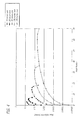
- Figure 4 is an exemplary graph showing the phase difference for TM and TE modes in a PWG with a TGG core and GGG claddings having a relatively small index difference, about 0.009, at a number of different core thicknesses.
- a relatively small index difference about 0.009
- equalization of the mode propagation velocities can be achieved by utilizing birefringent claddings and tuning the orientation of each birefringent cladding until the TE and TM propagation velocities are sufficiently equalized for the range of modes to be used in the PWG.
- Selection of cladding materials with the appropriate CTE to facilitate fabrication of a PWG and the optimal index and birefringence to equalize the propagation velocities can be challenging but several possible candidates exist for use with a TGG core.
- Figure 5 is an exemplary graph showing the phase difference for TM and TE modes in a PWG with a TGG core and CaWO4 claddings whose orientation has been optimized to minimize the difference between the effective index for TE and TM modes over a relatively broad range of modes.
- Figure 6 is an exemplary set of curves that show the calculated TE/TM phase difference for a number of different cladding refractive indices for the TM mode. This index range corresponds to tuning the optical axis of the birefringent cladding over a range from 15° to 21° relative to the axis of the PWG.
- the PWG Faraday isolator In addition to minimizing the difference between TE and TM mode propagation velocities, the PWG Faraday isolator must also minimize the temperature rise in the core and minimize stress-induced birefringence in order to maintain high extinction at high power. Fortunately, the PWG geometry also achieves these goals quite easily.
- the large surface area to volume ratio allows efficient cooling, minimizing temperature rise in the core and keeping stresses in the crystal very low.
- a notional 100kW PWG Faraday rotator might use a 200 micron TGG core with GGG claddings, a width of 5cm and a length of 2cm. Absorption in TGG is 0.15%/cm resulting in a 150W/cm heat load and a heat flux on the cooled surfaces of 15 W/cm2.
- the total thickness of the core and claddings might be 2mm yielding a temperature rise between the center of the core and the surface of the PWG of only 2.2°C. This small temperature rise would keep stress levels low resulting in negligible stress-induced birefringence and would avoid significant changes in the Faraday rotation due to the temperature dependence of the Verdet constant.
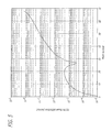
- FIG. 7 is a graph showing expected performance for an illustrative implementation of a Faraday rotator in accordance with the present teachings.
- the present invention of a PWG Faraday rotator optimized for low TE/TM propagation velocity difference provides a credible path to creating Faraday isolators with power handling up to HEL power levels.
- This type of device would be very useful in high gain Master Oscillator/Power Amplifier (MOPA) systems utilizing PWG amplifiers but is also generally useful for any high power laser system.
- MOPA Master Oscillator/Power Amplifier
- the optimal design for most applications is probably a 200 micron TGG core with GGG claddings.
- the length of the device would be on the order of 20 mm for the magnetic field strengths typically used.
- TGG and GGG have good bonding compatibility and good availability. This device should be capable of handling 100kW or more.
Landscapes
- Physics & Mathematics (AREA)
- General Physics & Mathematics (AREA)
- Optics & Photonics (AREA)
- Engineering & Computer Science (AREA)
- Microelectronics & Electronic Packaging (AREA)
- Optical Integrated Circuits (AREA)
- Optical Modulation, Optical Deflection, Nonlinear Optics, Optical Demodulation, Optical Logic Elements (AREA)
Abstract
Description
- The present invention relates to optical devices. More specifically, the present invention relates to Faraday rotators.
- Faraday rotators are used in laser systems to provide an optical isolator that allows light to travel in one direction and block light in the other direction. Optical isolators are useful in high power lasers to allow a low power laser to feed a high power amplifier and block the resulting high power beam from feeding back into the low power laser beam. This is particularly important in weapons class lasers inasmuch as these devices may operate at hundreds of kilowatt levels.
- Faraday Rotators are a type of optical device that provides a non-reciprocal rotation of the polarization of a light beam passing through the Faraday Rotator. The non-reciprocity of the polarization rotation allows creation of an optical isolator by placing a Faraday rotator with a 45 degree rotation between a pair of polarizers whose axes are rotated by 45 degrees with respect to each other. Faraday isolators act as optical diodes allowing a signal to pass with low loss in one direction while creating a high attenuation for signals traveling in the reverse direction. Faraday rotators consist of an optical material with a high Verdet constant that is placed in a strong magnetic field. The Faraday effect causes light traveling along the direction of the magnetic field to experience polarization rotation.
- Historically, use of Faraday rotators at high power levels (greater than a few 10s of watts) has been problematic because the optical materials used in Faraday rotators generally have some level of intrinsic residual absorption. At high average power levels, the heating due to this absorption in materials with useful Verdet constants causes a number of detrimental effects including thermal lensing: thermal gradients that lead to undesirable optical lensing effects, thermally induced stress birefringence, and thermally induced drift in the amount of rotation provided by the Faraday Rotator. These thermal effects degrade the effectiveness of the optical isolator, degrade the beam quality of the laser beam passing through the isolator, and/or result in optical damage to the isolator. Hence, there is a need for a means for managing the heat loads in Faraday rotators at high power levels in a way that minimizes these deleterious effects.
- Prior efforts to develop Faraday rotators capable of high power operation have focused on minimizing intrinsic absorption in the optical medium, configuring the optical medium as a rectangular slab in order to improve cooling and reduce thermal gradients, and compensating for birefringence by using two 22.5 degree Faraday rotators with a 90 degree reciprocal rotator between the Faraday rotators similar to Scott-DeWitt compensation applied to correct for birefringence in laser rods. The combination of all of these approaches by Khazanov has yielded Faraday Isolators with power handling up to 2 kW at greater than 20 db extinction. Unfortunately, this approach leads to rather large isolators and is unlikely to scale to 10s of kW.
- Hence, a need remains in the art for a Faraday rotator capable of operating at much higher power levels without performance degradation due to thermal gradients.
- The need in the art is addressed by the Faraday rotator and method for rotation of the present invention. In a most general implementation, the inventive rotator includes a planar core and a cladding disposed on opposite sides of thereof. In the best mode, the rotator includes a very low Numerical Aperture (NA) planar waveguide. The cladding refractive index and/or birefringence are optimized to provide equal mode propagation velocities for both TE and TM modes for at least one transverse mode. Preferably, the refractive index and/or birefringence of the cladding are optimized to provide equal mode propagation velocities for both TE and TM modes for a wide range of transverse modes.
- The inventive method for rotating a polarization state of a beam including the steps of: providing a planar core of a material with a non-zero Verdet constant; providing a cladding on opposite sides of said core; providing a magnetic field along the axis of the planar core; optimizing the refractive index and/or birefringence said cladding to provide equal mode propagation velocities for both TE and TM modes for at least one transverse mode; and inputting the beam into the core.
-
-
Figure 1 is a simplified perspective view of a Faraday rotator in accordance with conventional teachings. -
Figure 2 is a simplified perspective view of a Faraday rotator implemented in a planar waveguide in accordance with an illustrative embodiment of the present teachings. -
Figure 3 is an exemplary graph of the phase difference for transmitted TE and TM modes as a function of mode number in a Planar Waveguide (PWG) Faraday Rotator with a 100 micron Terbium Gallium Garnet (TGG) core and various claddings. -
Figure 4 is an exemplary graph showing the phase difference for transmitted TE and TM modes in a PWG with a TGG core and Gadolinium Gallium Garnet (GGG) claddings having a relatively small index difference, about 0.009, at a number of different core thicknesses. -
Figure 5 is an exemplary graph showing the phase difference for TE and TM modes in a PWG with a TGG core and Calcium Tungstate (CaWO4) claddings whose orientation has been optimized to minimize the difference between the effective index for TE and TM modes over a relatively broad range of modes. -
Figure 6 is an exemplary set of curves that show the calculated TE/TM phase difference for a number of different cladding refractive indices for the TM mode. -
Figure 7 is a graph showing expected performance for an illustrative implementation of a Faraday rotator in accordance with the present teachings. - Illustrative embodiments and exemplary applications will now be described with reference to the accompanying drawings to disclose the advantageous teachings of the present invention.
- While the present invention is described herein with reference to illustrative embodiments for particular applications, it should be understood that the invention is not limited thereto. Those having ordinary skill in the art and access to the teachings provided herein will recognize additional modifications, applications, and embodiments within the scope thereof and additional fields in which the present invention would be of significant utility.
- As discussed above in the Background of the Invention, Faraday Rotators are optical devices that provide a non-reciprocal rotation of the polarization of a light beam passing through the Faraday Rotator. The non-reciprocity of the polarization rotation allows creation of an optical isolator by placing a Faraday rotator with a 45° rotation between a pair of polarizers whose axes are rotated by 45° with respect to each other. Faraday isolators act as optical diodes allowing a signal to pass with low loss in one direction while creating a high attenuation for signals traveling in the reverse direction.
-
Figure 1 is a simplified perspective view of a Faraday rotator in accordance with conventional teachings. (See http://en.wikipedia.org/wiki/Faraday_rotator and "Encyclopedia of Laser Physics and Technology" online at www.rp-photonics.com.) As is known in the art, Faraday rotators typically consist of an optical material with a high Verdet constant that is placed in a strong magnetic field. The Faraday effect causes light traveling along the direction of the magnetic field to experience polarization rotation. Historically, using Faraday rotators at high power levels (greater than a few 10's of Watts) has been problematic because the optical materials used in Faraday rotators generally have some level of intrinsic absorption. At high average power levels, the heating due to this absorption causes a number of detrimental effects including thermal lensing, thermally induced stress birefringence, and thermally induced drift in the amount of rotation provided by the Faraday Rotator. The present invention provides a means of managing the heat loads at high power levels in a way that minimizes these deleterious effects by configuring the optical medium as a Planar Waveguide (PWG). - The present invention minimizes any phase difference for TE and TM modes in a PWG Faraday rotator through the use of a low NA PWG or through the use of a birefringent cladding around the core. The refractive index and/or birefringence of the cladding are optimized to provide equal mode propagation velocities for both TE and TM modes for a wide range of transverse modes. When the phase difference for TE and TM waves in the PWG Faraday rotator is less than about 0.01 waves, a Faraday isolator utilizing the PWG Faraday Rotator will be able to provide high extinction at high laser power levels.
-
Figure 2 is a simplified perspective view of a Faraday rotator implemented in a planar waveguide in accordance with an illustrative embodiment of the present teachings. In the best mode, therotator 10 is a very low Numerical Aperture (NA) planar waveguide. As shown inFigure 2 , therotator 10 comprises aplanar core 12, anupper cladding 14 and alower cladding 16. A magnetic field is applied along the optical axis of the PWG with a field strength optimized to provide a 45 degree rotation of the polarization of the propagating beam (an input TE or TM beam is converted to circular polarization after passing through the PWG Faraday Rotator). The end faces are coated with an antireflection coating at the laser wavelength. - In accordance with the present teachings, the upper and
lower claddings - The core material for a PWG Faraday rotator would ideally have very low absorption, high thermal conductivity, and a high Verdet constant. Terbium-doped glasses provide good performance for low power applications, but for high power applications, the favored materials are TGG and Yttrium Aluminum Garnet (YAG). TGG has a much stronger Verdet constant than YAG meaning much weaker magnets and/or smaller crystal sizes are required to achieve the desired amount of rotation. YAG may, however, hold the highest power scaling limits due to it's 1.5x higher thermal conductivity and the availability of very high purity YAG with extremely low absorption levels, nearly 3 orders of magnitude less than TGG. Due to YAG's ∼10x lower Verdet constant than TGG, a device with a YAG core would need to be longer and may require more powerful magnets.
-
Figure 3 is an exemplary graph of the phase difference as a function of mode number for TM and TE modes in a PWG Faraday Rotator with a 100 micron TGG core and various claddings. The YAG and Spinel claddings have a relatively large index difference relative to the core and for higher order modes the mode propagation velocities differ enough to cause adverse effects. For example, to maintain an extinction ratio of 20 db, the phase difference between TE and TM modes should be less than 0.03 waves. To maintain an extinction ratio of 30 db, the phase difference between TE and TM modes should be less than 0.01 waves. - For applications where only a single guided mode or just a few guided modes must be propagated in the PWG Faraday rotator, a TGG PWG with even a moderately large core/cladding index difference, up to 0.2 or more, should provide an adequately low TE/TM mode phase difference to be used as a Faraday Rotator. When higher order modes must be propagated, a low index difference between the core and cladding should sufficiently equalize the propagation velocities for TE and TM modes. In this case, the core: cladding index difference should be on the order of 0.01 or less. Index differences in this range may be achieved by selection of core and cladding materials with appropriate properties. Engineered approaches using the same core and cladding material may also be produced by adding low concentrations of a passive dopant to the core and/or cladding of the PWG to modify the refractive index.
-
Figure 4 is an exemplary graph showing the phase difference for TM and TE modes in a PWG with a TGG core and GGG claddings having a relatively small index difference, about 0.009, at a number of different core thicknesses. For low order modes, there is a negligible difference between the effective index for TE and TM modes for cores thicker than about 20 microns. The performance even for high order modes appears to be very good for core sizes in the range of 100 - 200 microns. - For applications where a highly multimode beam must be transmitted by the
PWG Faraday rotator 10 of the present invention, equalization of the mode propagation velocities can be achieved by utilizing birefringent claddings and tuning the orientation of each birefringent cladding until the TE and TM propagation velocities are sufficiently equalized for the range of modes to be used in the PWG. Selection of cladding materials with the appropriate CTE to facilitate fabrication of a PWG and the optimal index and birefringence to equalize the propagation velocities can be challenging but several possible candidates exist for use with a TGG core. -
Figure 5 is an exemplary graph showing the phase difference for TM and TE modes in a PWG with a TGG core and CaWO4 claddings whose orientation has been optimized to minimize the difference between the effective index for TE and TM modes over a relatively broad range of modes. - Optimization of the orientation of the birefringent cladding is relatively sensitive but not beyond typical fabrication tolerances of course of ordinary skill in the art.
-
Figure 6 is an exemplary set of curves that show the calculated TE/TM phase difference for a number of different cladding refractive indices for the TM mode. This index range corresponds to tuning the optical axis of the birefringent cladding over a range from 15° to 21° relative to the axis of the PWG. - In addition to minimizing the difference between TE and TM mode propagation velocities, the PWG Faraday isolator must also minimize the temperature rise in the core and minimize stress-induced birefringence in order to maintain high extinction at high power. Fortunately, the PWG geometry also achieves these goals quite easily. The large surface area to volume ratio allows efficient cooling, minimizing temperature rise in the core and keeping stresses in the crystal very low. A notional 100kW PWG Faraday rotator might use a 200 micron TGG core with GGG claddings, a width of 5cm and a length of 2cm. Absorption in TGG is 0.15%/cm resulting in a 150W/cm heat load and a heat flux on the cooled surfaces of 15 W/cm2. The total thickness of the core and claddings might be 2mm yielding a temperature rise between the center of the core and the surface of the PWG of only 2.2°C. This small temperature rise would keep stress levels low resulting in negligible stress-induced birefringence and would avoid significant changes in the Faraday rotation due to the temperature dependence of the Verdet constant.
-
Figure 7 is a graph showing expected performance for an illustrative implementation of a Faraday rotator in accordance with the present teachings. The present invention of a PWG Faraday rotator optimized for low TE/TM propagation velocity difference provides a credible path to creating Faraday isolators with power handling up to HEL power levels. This type of device would be very useful in high gain Master Oscillator/Power Amplifier (MOPA) systems utilizing PWG amplifiers but is also generally useful for any high power laser system. The optimal design for most applications is probably a 200 micron TGG core with GGG claddings. The length of the device would be on the order of 20 mm for the magnetic field strengths typically used. TGG and GGG have good bonding compatibility and good availability. This device should be capable of handling 100kW or more. - Thus, the present invention has been described herein with reference to a particular embodiment for a particular application. Those having ordinary skill in the art and access to the present teachings will recognize additional modifications applications and embodiments within the scope thereof.
- It is therefore intended by the appended claims to cover any and all such applications, modifications and embodiments within the scope of the present invention.
Claims (8)
- A Faraday rotator comprising:a planar core anda cladding disposed on opposite sides of said core.
- The rotator of claim 1 wherein said cladding is a birefringent cladding.
- The rotator of claim 1 or 2 wherein said rotator includes a very low numerical aperture planar waveguide.
- The rotator of any preceding claim wherein the refractive index of the cladding is optimized to provide equal mode propagation velocities for both TE and TM modes for at least one transverse mode.
- The rotator of claim 4 wherein the refractive index of the cladding is optimized to provide equal mode propagation velocities for both TE and TM modes for a wide range of transverse modes.
- The rotator of claim 2 wherein said cladding has a refractive index and birefringence optimized to provide equal mode propagation velocities for both TE and TM modes for at least one transverse mode.
- The rotator of claim 6 wherein the refractive index and birefringence of the cladding are optimized to provide equal mode propagation velocities for both TE and TM modes for a wide range of transverse modes.
- A method for rotating a polarization state of a beam including the steps of:-providing a planar core with a Verdet constant;providing a birefringent cladding on opposite sides of said core;applying a magnetic field along the axis of the planar core;optimizing the refractive index and birefringence of said cladding to provide equal mode propagation velocities for both TE and TM modes for at least one transverse mode; andinputting said beam into said core.
Applications Claiming Priority (1)
| Application Number | Priority Date | Filing Date | Title |
|---|---|---|---|
| US12/925,184 US9405127B2 (en) | 2010-10-14 | 2010-10-14 | Planar waveguide faraday rotator |
Publications (2)
| Publication Number | Publication Date |
|---|---|
| EP2442174A2 true EP2442174A2 (en) | 2012-04-18 |
| EP2442174A3 EP2442174A3 (en) | 2012-11-28 |
Family
ID=44582610
Family Applications (1)
| Application Number | Title | Priority Date | Filing Date |
|---|---|---|---|
| EP11180665A Withdrawn EP2442174A3 (en) | 2010-10-14 | 2011-09-09 | Planar waveguide Faraday rotator |
Country Status (3)
| Country | Link |
|---|---|
| US (1) | US9405127B2 (en) |
| EP (1) | EP2442174A3 (en) |
| IL (1) | IL214769A0 (en) |
Families Citing this family (3)
| Publication number | Priority date | Publication date | Assignee | Title |
|---|---|---|---|---|
| US9646639B2 (en) | 2015-06-26 | 2017-05-09 | Western Digital (Fremont), Llc | Heat assisted magnetic recording writer having integrated polarization rotation waveguides |
| US10466515B2 (en) | 2016-03-15 | 2019-11-05 | Intel Corporation | On-chip optical isolator |
| US20180059446A1 (en) * | 2016-08-29 | 2018-03-01 | Woosung Kim | Optical iso-modulator |
Citations (1)
| Publication number | Priority date | Publication date | Assignee | Title |
|---|---|---|---|---|
| US5175787A (en) * | 1991-05-28 | 1992-12-29 | Allied-Signal Inc. | Birefringent optical waveguides of aluminum garnet |
Family Cites Families (5)
| Publication number | Priority date | Publication date | Assignee | Title |
|---|---|---|---|---|
| DE3341482A1 (en) * | 1983-11-17 | 1985-05-30 | Philips Patentverwaltung Gmbh, 2000 Hamburg | MAGNETO-OPTICAL WAVE GUIDE STRUCTURE WITH ARTIFICIAL OPTICAL ANISOTROPY |
| DE3520991A1 (en) | 1985-06-12 | 1986-12-18 | Philips Patentverwaltung Gmbh, 2000 Hamburg | MAGNETO-OPTICAL WAVE LEAD STRUCTURE FOR CONVERSION OF FASHIONS GUIDED IN THE STRUCTURE |
| DE3904660A1 (en) * | 1989-02-16 | 1990-08-23 | Philips Patentverwaltung | PLANAR OPTICAL ISOLATOR |
| US5245689A (en) * | 1991-05-28 | 1993-09-14 | Allied-Signal Inc. | Magneto-optical waveguides of aluminum garnet |
| US7065121B2 (en) * | 2001-07-24 | 2006-06-20 | Gsi Group Ltd. | Waveguide architecture, waveguide devices for laser processing and beam control, and laser processing applications |
-
2010
- 2010-10-14 US US12/925,184 patent/US9405127B2/en active Active
-
2011
- 2011-08-21 IL IL214769A patent/IL214769A0/en active IP Right Grant
- 2011-09-09 EP EP11180665A patent/EP2442174A3/en not_active Withdrawn
Patent Citations (1)
| Publication number | Priority date | Publication date | Assignee | Title |
|---|---|---|---|---|
| US5175787A (en) * | 1991-05-28 | 1992-12-29 | Allied-Signal Inc. | Birefringent optical waveguides of aluminum garnet |
Also Published As
| Publication number | Publication date |
|---|---|
| EP2442174A3 (en) | 2012-11-28 |
| IL214769A0 (en) | 2012-02-29 |
| US9405127B2 (en) | 2016-08-02 |
| US20120093454A1 (en) | 2012-04-19 |
Similar Documents
| Publication | Publication Date | Title |
|---|---|---|
| EP2175533B1 (en) | Planar waveguide laser apparatus | |
| Karki et al. | Thin-film magnetless Faraday rotators for compact heterogeneous integrated optical isolators | |
| US8547636B1 (en) | Tunable magnet structure | |
| US20140300963A1 (en) | Optical Isolator | |
| JP5439669B2 (en) | Polarization-independent optical isolator | |
| Kawaguchi et al. | Optical isolator based on chiral light-matter interactions in a ring resonator integrating a dichroic magneto-optical material | |
| Karki et al. | Broadband bias-magnet-free on-chip optical isolators with integrated thin film polarizers | |
| US9405127B2 (en) | Planar waveguide faraday rotator | |
| JPWO2009016972A1 (en) | Optical device, optical integrated device, and manufacturing method thereof | |
| US20150124318A1 (en) | High magnetic field-type multi-pass faraday rotator | |
| Nicklaus et al. | Optical isolator for unpolarized laser radiation at multi-kilowatt average power | |
| US6833941B2 (en) | Magneto-optic optical device | |
| JP5991491B2 (en) | Faraday rotator | |
| JP4797733B2 (en) | Polarization-independent optical isolator for high-power lasers | |
| US7002732B2 (en) | Magneto-optical devices | |
| Sung et al. | Magneto-optical garnet waveguides on semiconductor platforms: Magnetics, mechanics, and photonics | |
| JP2009168894A (en) | Optical isolator | |
| JP5439670B2 (en) | Polarization-independent optical isolator | |
| Schlichting et al. | Commercializing potassium terbium fluoride, KTF (KTb3F10) faraday crystals for high laser power optical isolator applications | |
| US11754866B2 (en) | Gas cooled faraday rotator and method | |
| US20250314919A1 (en) | Optical isolator for high average power and high pulse energy lasers | |
| CN101655612A (en) | High-power optical fiber isolator | |
| Starobor et al. | Compensation of thermally induced distortions in a GGG-based cryogenic Faraday isolator | |
| CN201242628Y (en) | High-power optical fiber isolator | |
| Yokoi et al. | Integrating laser diode and optical isolator by photosensitive adhesive bonding |
Legal Events
| Date | Code | Title | Description |
|---|---|---|---|
| PUAI | Public reference made under article 153(3) epc to a published international application that has entered the european phase |
Free format text: ORIGINAL CODE: 0009012 |
|
| AK | Designated contracting states |
Kind code of ref document: A2 Designated state(s): AL AT BE BG CH CY CZ DE DK EE ES FI FR GB GR HR HU IE IS IT LI LT LU LV MC MK MT NL NO PL PT RO RS SE SI SK SM TR |
|
| AX | Request for extension of the european patent |
Extension state: BA ME |
|
| PUAL | Search report despatched |
Free format text: ORIGINAL CODE: 0009013 |
|
| AK | Designated contracting states |
Kind code of ref document: A3 Designated state(s): AL AT BE BG CH CY CZ DE DK EE ES FI FR GB GR HR HU IE IS IT LI LT LU LV MC MK MT NL NO PL PT RO RS SE SI SK SM TR |
|
| AX | Request for extension of the european patent |
Extension state: BA ME |
|
| RIC1 | Information provided on ipc code assigned before grant |
Ipc: G02F 1/095 20060101AFI20121023BHEP |
|
| 17P | Request for examination filed |
Effective date: 20130528 |
|
| RBV | Designated contracting states (corrected) |
Designated state(s): AL AT BE BG CH CY CZ DE DK EE ES FI FR GB GR HR HU IE IS IT LI LT LU LV MC MK MT NL NO PL PT RO RS SE SI SK SM TR |
|
| 17Q | First examination report despatched |
Effective date: 20171012 |
|
| GRAP | Despatch of communication of intention to grant a patent |
Free format text: ORIGINAL CODE: EPIDOSNIGR1 |
|
| INTG | Intention to grant announced |
Effective date: 20191021 |
|
| STAA | Information on the status of an ep patent application or granted ep patent |
Free format text: STATUS: THE APPLICATION IS DEEMED TO BE WITHDRAWN |
|
| 18D | Application deemed to be withdrawn |
Effective date: 20200303 |