EP2442121A2 - Acoustic sensor system, acoustic signature simulator, and electrical distribution system - Google Patents
Acoustic sensor system, acoustic signature simulator, and electrical distribution system Download PDFInfo
- Publication number
- EP2442121A2 EP2442121A2 EP11008369A EP11008369A EP2442121A2 EP 2442121 A2 EP2442121 A2 EP 2442121A2 EP 11008369 A EP11008369 A EP 11008369A EP 11008369 A EP11008369 A EP 11008369A EP 2442121 A2 EP2442121 A2 EP 2442121A2
- Authority
- EP
- European Patent Office
- Prior art keywords
- acoustic
- electrical
- structured
- distribution system
- sensors
- Prior art date
- Legal status (The legal status is an assumption and is not a legal conclusion. Google has not performed a legal analysis and makes no representation as to the accuracy of the status listed.)
- Granted
Links
- 230000005534 acoustic noise Effects 0.000 claims abstract description 14
- 230000003278 mimic effect Effects 0.000 claims abstract description 6
- 239000004020 conductor Substances 0.000 claims description 57
- 125000006850 spacer group Chemical group 0.000 claims description 15
- 238000009413 insulation Methods 0.000 claims description 13
- 239000000919 ceramic Substances 0.000 claims description 4
- 238000001514 detection method Methods 0.000 description 8
- 229910052751 metal Inorganic materials 0.000 description 5
- 239000002184 metal Substances 0.000 description 5
- 238000000034 method Methods 0.000 description 4
- 230000008569 process Effects 0.000 description 4
- 229910001220 stainless steel Inorganic materials 0.000 description 4
- 239000010935 stainless steel Substances 0.000 description 4
- 230000000903 blocking effect Effects 0.000 description 3
- 239000011248 coating agent Substances 0.000 description 3
- 238000000576 coating method Methods 0.000 description 3
- 230000007246 mechanism Effects 0.000 description 3
- 238000012360 testing method Methods 0.000 description 3
- 239000000853 adhesive Substances 0.000 description 2
- 230000001070 adhesive effect Effects 0.000 description 2
- 238000010586 diagram Methods 0.000 description 2
- 238000012544 monitoring process Methods 0.000 description 2
- 238000005457 optimization Methods 0.000 description 2
- 230000036316 preload Effects 0.000 description 2
- RYGMFSIKBFXOCR-UHFFFAOYSA-N Copper Chemical compound [Cu] RYGMFSIKBFXOCR-UHFFFAOYSA-N 0.000 description 1
- 239000006096 absorbing agent Substances 0.000 description 1
- 229910052782 aluminium Inorganic materials 0.000 description 1
- XAGFODPZIPBFFR-UHFFFAOYSA-N aluminium Chemical compound [Al] XAGFODPZIPBFFR-UHFFFAOYSA-N 0.000 description 1
- 230000005540 biological transmission Effects 0.000 description 1
- 229910052802 copper Inorganic materials 0.000 description 1
- 239000010949 copper Substances 0.000 description 1
- 230000008878 coupling Effects 0.000 description 1
- 238000010168 coupling process Methods 0.000 description 1
- 238000005859 coupling reaction Methods 0.000 description 1
- 238000013461 design Methods 0.000 description 1
- 238000009429 electrical wiring Methods 0.000 description 1
- 238000005516 engineering process Methods 0.000 description 1
- 231100001261 hazardous Toxicity 0.000 description 1
- 230000006872 improvement Effects 0.000 description 1
- 238000003331 infrared imaging Methods 0.000 description 1
- 238000002955 isolation Methods 0.000 description 1
- 239000000463 material Substances 0.000 description 1
- 238000012986 modification Methods 0.000 description 1
- 230000004048 modification Effects 0.000 description 1
- 230000003252 repetitive effect Effects 0.000 description 1
- 239000007787 solid Substances 0.000 description 1
- 239000010409 thin film Substances 0.000 description 1
Images





Classifications
-
- G—PHYSICS
- G01—MEASURING; TESTING
- G01R—MEASURING ELECTRIC VARIABLES; MEASURING MAGNETIC VARIABLES
- G01R31/00—Arrangements for testing electric properties; Arrangements for locating electric faults; Arrangements for electrical testing characterised by what is being tested not provided for elsewhere
- G01R31/08—Locating faults in cables, transmission lines, or networks
-
- G—PHYSICS
- G01—MEASURING; TESTING
- G01R—MEASURING ELECTRIC VARIABLES; MEASURING MAGNETIC VARIABLES
- G01R31/00—Arrangements for testing electric properties; Arrangements for locating electric faults; Arrangements for electrical testing characterised by what is being tested not provided for elsewhere
- G01R31/12—Testing dielectric strength or breakdown voltage ; Testing or monitoring effectiveness or level of insulation, e.g. of a cable or of an apparatus, for example using partial discharge measurements; Electrostatic testing
- G01R31/1209—Testing dielectric strength or breakdown voltage ; Testing or monitoring effectiveness or level of insulation, e.g. of a cable or of an apparatus, for example using partial discharge measurements; Electrostatic testing using acoustic measurements
-
- G—PHYSICS
- G01—MEASURING; TESTING
- G01R—MEASURING ELECTRIC VARIABLES; MEASURING MAGNETIC VARIABLES
- G01R31/00—Arrangements for testing electric properties; Arrangements for locating electric faults; Arrangements for electrical testing characterised by what is being tested not provided for elsewhere
- G01R31/12—Testing dielectric strength or breakdown voltage ; Testing or monitoring effectiveness or level of insulation, e.g. of a cable or of an apparatus, for example using partial discharge measurements; Electrostatic testing
- G01R31/1227—Testing dielectric strength or breakdown voltage ; Testing or monitoring effectiveness or level of insulation, e.g. of a cable or of an apparatus, for example using partial discharge measurements; Electrostatic testing of components, parts or materials
- G01R31/1263—Testing dielectric strength or breakdown voltage ; Testing or monitoring effectiveness or level of insulation, e.g. of a cable or of an apparatus, for example using partial discharge measurements; Electrostatic testing of components, parts or materials of solid or fluid materials, e.g. insulation films, bulk material; of semiconductors or LV electronic components or parts; of cable, line or wire insulation
- G01R31/1272—Testing dielectric strength or breakdown voltage ; Testing or monitoring effectiveness or level of insulation, e.g. of a cable or of an apparatus, for example using partial discharge measurements; Electrostatic testing of components, parts or materials of solid or fluid materials, e.g. insulation films, bulk material; of semiconductors or LV electronic components or parts; of cable, line or wire insulation of cable, line or wire insulation, e.g. using partial discharge measurements
-
- H—ELECTRICITY
- H02—GENERATION; CONVERSION OR DISTRIBUTION OF ELECTRIC POWER
- H02H—EMERGENCY PROTECTIVE CIRCUIT ARRANGEMENTS
- H02H1/00—Details of emergency protective circuit arrangements
- H02H1/0007—Details of emergency protective circuit arrangements concerning the detecting means
- H02H1/0015—Using arc detectors
- H02H1/0023—Using arc detectors sensing non electrical parameters, e.g. by optical, pneumatic, thermal or sonic sensors
-
- H—ELECTRICITY
- H02—GENERATION; CONVERSION OR DISTRIBUTION OF ELECTRIC POWER
- H02H—EMERGENCY PROTECTIVE CIRCUIT ARRANGEMENTS
- H02H7/00—Emergency protective circuit arrangements specially adapted for specific types of electric machines or apparatus or for sectionalised protection of cable or line systems, and effecting automatic switching in the event of an undesired change from normal working conditions
- H02H7/22—Emergency protective circuit arrangements specially adapted for specific types of electric machines or apparatus or for sectionalised protection of cable or line systems, and effecting automatic switching in the event of an undesired change from normal working conditions for distribution gear, e.g. bus-bar systems; for switching devices
-
- G—PHYSICS
- G01—MEASURING; TESTING
- G01R—MEASURING ELECTRIC VARIABLES; MEASURING MAGNETIC VARIABLES
- G01R31/00—Arrangements for testing electric properties; Arrangements for locating electric faults; Arrangements for electrical testing characterised by what is being tested not provided for elsewhere
- G01R31/08—Locating faults in cables, transmission lines, or networks
- G01R31/081—Locating faults in cables, transmission lines, or networks according to type of conductors
- G01R31/086—Locating faults in cables, transmission lines, or networks according to type of conductors in power transmission or distribution networks, i.e. with interconnected conductors
-
- G—PHYSICS
- G01—MEASURING; TESTING
- G01R—MEASURING ELECTRIC VARIABLES; MEASURING MAGNETIC VARIABLES
- G01R31/00—Arrangements for testing electric properties; Arrangements for locating electric faults; Arrangements for electrical testing characterised by what is being tested not provided for elsewhere
- G01R31/50—Testing of electric apparatus, lines, cables or components for short-circuits, continuity, leakage current or incorrect line connections
- G01R31/66—Testing of connections, e.g. of plugs or non-disconnectable joints
Definitions
- the disclosed concept pertains generally to acoustic noise induced by electrical conductivity faults and, more particularly, to acoustic sensor systems.
- the disclosed concept also pertains to acoustic signature simulators.
- the disclosed concept further pertains to electrical distribution systems.
- switchgears, switchboards and motor control centers are custom designed and built. This makes it impossible to have a one-fit-all layout design of an acoustic sensing system for these power distribution systems.
- U.S. Patent No. 7,148,696 discloses that an acoustic signature is generated by an arc fault or a glowing contact.
- An acoustic sensor "listens" directly to signature noise generated by a fault, no matter what type of electrical load is present or in what kind of environment in which the fault is generated.
- the acoustic noise generated by an arc fault or a glowing contact has an acoustic signal at one or more specific wavelengths that is (are) directly related to either the basic characteristics of, for example, the arc and its resonance frequency or the AC power source modulated frequency and its harmonics.
- the acoustic signal of an arc fault is detected by an acoustic sensor.
- a resulting trip signal is sent to a trip mechanism to, for example, trip open separable contacts, in order to interrupt the arc fault.
- U.S. Patent No. 7,411,403 discloses a circuit breaker that detects a loose electrical connection condition of a power circuit.
- the circuit breaker includes first and second lugs, and first and second acoustic couplers acoustically coupled to the power circuit.
- An acoustic generator is coupled to the second acoustic coupler and generates a first acoustic signal to the power circuit from the second acoustic coupler.
- An acoustic sensor is coupled to the first acoustic coupler and has a second acoustic signal which is operatively associated with the loose electrical connection condition. The acoustic sensor outputs a sensed acoustic signal.
- a circuit cooperates with the acoustic generator to generate the first acoustic signal, input the sensed acoustic signal, and detect the loose electrical connection condition therefrom.
- the circuit can output a trip signal to a trip mechanism upon detecting an electrical conductivity fault from the sensed acoustic signal.
- embodiments of the disclosed concept which employs acoustic sensors, an acoustic transmitter and/or an acoustic signature simulator to sense noise signals corresponding to electrical conductivity faults and/or to mimic acoustic noise induced by electrical conductivity faults.
- an acoustic sensor system comprises: a first plurality of acoustic sensors; and an acoustic transmitter structured to generate acoustic noise to mimic acoustic noise induced by an electrical conductivity fault, wherein a smaller second number of acoustic sensors of the first plurality of acoustic sensors are structured to identify a plurality of locations in an electrical distribution system having a plurality of electrical joints, in order that the smaller second number of acoustic sensors can monitor all of the plurality of electrical joints of the electrical distribution system.
- At least one of the first plurality of acoustic sensors may be structured to be enabled as the acoustic transmitter with a high voltage pulse circuit.
- the acoustic transmitter may be structured to be moved to a plurality of different locations in the electrical distribution system.
- an acoustic signature simulator comprises: a pulse repetition rate control circuit structured to output a plurality of first pulses at one of a number of repetition rates; a voltage pulse generating circuit structured to output a plurality of second voltage pulses responsive to the plurality of first pulses; an acoustic generator structured to output a plurality of mechanical pulses responsive to the plurality of second voltage pulses; and an interface structured to couple the plurality of mechanical pulses to an electrical power conductor.
- an electrical distribution system comprises: a plurality of electrical conductors comprising a plurality of electrical joints; a plurality of circuit interrupters, each of the circuit interrupters being electrically interconnected with a number of the plurality of electrical conductors; and a plurality of acoustic sensors, wherein the plurality of electrical conductors form a common bus structure, and wherein each of the plurality of acoustic sensors is coupled to a corresponding one of the plurality of electrical conductors, covers a number of the electrical joints of the corresponding one of the plurality of electrical conductors, and is structured to sense a noise signal corresponding to an electrical conductivity fault of the number of the electrical joints.
- Each of a plurality of the plurality of acoustic sensors may sense a corresponding noise signal. Location of the electrical conductivity fault may be defined by the corresponding noise signal being the strongest noise signal of the plurality of the plurality of acoustic sensors.
- number shall mean one or an integer greater than one ( i.e., a plurality).
- acoustic shall mean one or more sounds that are subsonic, sonic and/or ultrasonic.
- electrical power conductor shall mean a wire (e.g., solid; stranded; insulated; non-insulated), a copper conductor, an aluminum conductor, a suitable metal conductor, an electrical bus bar, or other suitable material or object that permits an electric current to flow easily.
- electrical joint shall mean a structure that electrically and mechanically connects a plurality of electrical conductors.
- lug shall mean a terminal or other electrically conductive fitting to which two or more electrical conductors are electrically and mechanically connected.
- electrical conductivity fault shall mean an arc fault, or a loose or other intermittent electrical connection of an electrical conductor, an electrical joint and/or a lug that leads to a glowing contact.
- acoustic coupler shall mean a bolt; an adhesive; a clamp; a fastener; or another suitable coupling mechanism to hold an electrical conductor and an acoustic sensor or an acoustic generator together to allow effective acoustic transmission with or without an electrical connection.
- acoustic signature shall mean something that serves to set apart or identify another thing.
- an acoustic signature serves to set apart or identify an electrical conductivity fault.
- fastener shall mean rivets, adhesives, screws, bolts and the combinations of bolts and nuts (e.g., without limitation, lock nuts) and bolts, washers and nuts.
- bolt shall mean a device or apparatus structured to bolt two or more parts together so as to hold them firmly, such as by bolting an electrical power conductor and a housing including an insulation spacer.
- a bolt can be, for example, a metal rod or pin for fastening objects together that usually has a head at one end and a screw thread at the other end and is secured by a nut.
- clamp shall mean a device or apparatus structured to bind or constrict or to press two or more parts together so as to hold them firmly, such as by holding or compressing an electrical power conductor and an insulation spacer.
- clamp expressly excludes a fastener.
- the disclosed concept is described in association with, for example and without limitation, three-phase electrical distribution equipment and systems, such as low voltage switchgear, low voltage switch boards, low voltage panel boards, motor control centers and medium voltage switchgear.
- three-phase electrical distribution equipment and systems such as low voltage switchgear, low voltage switch boards, low voltage panel boards, motor control centers and medium voltage switchgear.
- the disclosed concept can be employed with a wide range of other applications, such as busway electrical systems for commercial or industrial facilities, aerospace applications, and electric vehicle applications.
- the disclosed concept is not limited to three-phase applications and can be applied to residential or other single-phase applications.
- the acoustic signal has a relatively high attenuation rate with relatively small electrical conductors; hence, each acoustic sensor can cover only a relatively short range of the electrical wiring system.
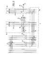
- Figure 1 shows an electrical distribution system, such as switchgear 2, including an acoustic signature simulator 4 and acoustic sensors 6,8,10,12,14,16.
- the example acoustic signature simulator 2 includes an acoustic generator, such as a piezoelectric acoustic transmitter 18, to generate an acoustic signal 20 that mimics an acoustic signal of an electrical conductivity fault, such as an arc fault, a glowing contact or a loose electrical connection that leads to a glowing contact, such as 22 or 24 of Figures 1 and 2 .
- an acoustic generator such as a piezoelectric acoustic transmitter 18 to generate an acoustic signal 20 that mimics an acoustic signal of an electrical conductivity fault, such as an arc fault, a glowing contact or a loose electrical connection that leads to a glowing contact, such as 22 or 24 of Figures 1 and 2 .
- any suitable electrical, mechanical or electro-mechanical acoustic generator, or magnetostrictive device can be employed to simulate acoustic noise generated by an electrical conductivity fault (e.g., the generated acoustic signal wavelet resembles that induced by an electrical conductivity fault with a repetitive rate of a power frequency or its harmonics).
- the example piezoelectric acoustic transmitter 18 can be coupled to different locations of an electrical distribution system, such as the example switchgear 2, to determine where acoustic sensors, such as 6,8,10,12,14,16, should be positioned, in order to provide complete detection coverage for loose electrical connections 22,24 of respective zones 26,28.
- circuit interrupters such as circuit breakers 30,34,36, act as isolators or absorbers of acoustic signals since, for example, the braided flexible conductor or shunt (not shown) electrically connecting the movable contact arm (not shown) and the circuit breaker load side conductor (not shown) acts like an acoustic isolator due to the relatively high attenuation rate of the acoustic signal when it goes through the shunt.
- an acoustic signal from the load (line) side cannot pass through the circuit breaker to reach to the line (load) side.
- any acoustic signal regardless if generated from an actual loose electrical connection or a simulator, will not pass through the circuit breaker, thus dividing the switchgear 2 into acoustically isolated zones, such as 26,28.
- the example circuit breaker 34 is a three-pole circuit breaker.
- the example circuit breaker 30 is a six-pole circuit breaker with two poles paralleled per phase. However, it will be appreciated that a three-pole circuit breaker could be employed.
- the example piezoelectric acoustic transmitter 18 of Figure 4 can be part of a suitable acoustic sensor (e.g., without limitation, a piezoelectric sensor), such as acoustic sensors 6,8,10,12,14,16.
- a suitable acoustic sensor e.g., without limitation, a piezoelectric sensor
- each phase employs a corresponding piezoelectric acoustic sensor. So, for instance, for a three-phase system, there are three acoustic sensors, one for each phase.
- the loose electrical connection 24 is detected by sensor 8 in zone 28 (zone #2).
- the acoustic signal 20 ( Figure 4 ) from acoustic signature simulator 4 can also detected by sensor 8 in zone 28.
- the loose electrical connection 22 is not detected by sensor 8 due to blocking by circuit breaker 30.
- Sensors 14,16 by themselves are unable to detect the loose electrical connection 24 due to the attenuation of the acoustic signal, or may not be able to confirm that the loose electrical connection 24 is in zone 28 (zone #2) due to the relatively low level of noise detected by those sensors 14,16 when compared with the relatively higher level of noise detected by sensor 8 in zone 28.
- Figures 2 and 3 show variations of how the example switchgear 2 works in terms of the simulator 4, the example zones 26,28, the example acoustic sensors 6,8 and the circuit breaker 30 (that provides acoustic isolation). This can either use the simulator 4 to optimize locations of the sensors 6,8,10,12,14,16, or use the sensors 6,8 to detect locations of loose electrical connections 22,24.
- the simulator 4 is moved to a different location; otherwise, the switchgear 2 is the same as the switchgear 2 shown in Figure 1 .
- the loose electrical connection 22 is detected by sensor 6 in zone 26 (zone #1). However, the loose electrical connection 22 is not detected by sensors 8,10,12,14,16 due to blocking by circuit breaker 30, and is not detected by sensors 10,12 due to further blocking by circuit breakers 34,36.
- the simulator 4 is moved to a different location; otherwise, the switchgear 2 is the same as the switchgear 2 shown in Figure 1 .
- the location of loose electrical connection 38 can be "pinpointed” through “triangulation”. Loose electrical connection 38 can be detected and located by comparing measured noise values by sensors 8,14,16. For example, sensor 16 will measure the strongest noise signal, followed by sensor 8 and then by sensor 14. Hence, the loose electrical connection 38 can be confirmed to be part of the common bus structure formed by three-phase buses 40,42,44 shared by those respective sensors 8,14,16, but in relatively closer proximity to sensor 16 on bus 44 rather than sensors 8 or 14 on respective buses 40 or 42.
- FIG 4 shows the example acoustic signature simulator 4 of Figures 1-3 .
- the simulator 4 including the circuit 50 can be powered by an external power supply 46 through a power switch 48, as shown.
- the power lines may not be energized during testing.
- a battery can be employed as the power supply 46.
- the circuit 50 provides a number of repetition rates of electronic pulses 52.
- the pulses 52 trigger a voltage pulse generating circuit 54 at a number of suitable voltages (e.g., without limitation, 150V; 400V; any suitable voltage to provide a suitable acoustic pulse amplitude).
- the output voltage pulses 56 drive the example piezoelectric element 18 to generate mechanical pulses 57 through a suitable interface, such as insulation spacer 58 (e.g., without limitation, a ceramic disk), onto a suitable electrical power conductor, such as bus bar or electrical cable 60, in order to simulate a plurality of acoustic signals 20 induced by loose electrical connections (e.g., without limitation, over-heated electrical joints (not shown, but see electrical joints 61 and loose electrical connections 22,24,38 of Figures 1-3 )).
- the example insulation spacer 58 is disposed between the example piezoelectric element 18 (or a piezoelectric element housing (not shown)) and the example bus bar 60.
- the optional "preload" 62 of the example piezoelectric element 18 optionally compresses the piezoelectric element 18 under pressure in its assembly.
- the example piezoelectric element 18 can either be preloaded to the example insulation spacer 58, or is not preloaded thereto.
- the circuit 50 can include a selection circuit 64 that selects one of a plurality of different high voltages, and a control circuit 66 that provides the electronic pulses 52 at a suitable repetition rate, such as, for example, that of a line frequency.
- the example acoustic signature simulator 4 includes the pulse repetition rate control circuit 66 structured to output the first pulses 52 at one of a number of repetition rates, the voltage pulse generating circuit 54 structured to output the second voltage pulses 56 responsive to the first pulses 52, the example piezoelectric element 18 structured to output the mechanical pulses 57 responsive to the second voltage pulses 56, and the interface 58 structured to couple the mechanical pulses 57 to the electrical power conductor 60.
- the voltage pulse generating circuit 54 can be structured to output the second voltage pulses 56 at a plurality of different voltages (e.g., without limitation, 150V, 400V, any suitable voltage). For example, this can simulate an acoustic signal induced by a loose connection at different locations, different current levels, or even just a variation of acoustic signals generated by the same loose connection. This can include multiple voltages at the same time to simulate the variation of an acoustic signal from a loose electrical connection or just one selected voltage.
- a plurality of different voltages e.g., without limitation, 150V, 400V, any suitable voltage
- the pulse repetition rate control circuit 66 can be structured to select one of a plurality of different repetition rates (e.g., without limitation, corresponding to 50 Hz, 60 Hz, 85 Hz, 120 Hz, 135 Hz, 400 Hz, harmonics and sub-harmonics of the line frequency, any suitable frequency). This can be employed to, for example and without limitation, test an acoustic sensor's detection capability and nuisance detection performance. This can permit a wide range of power line applications (e.g., 60 Hz in the United States; 50 Hz in Europe and Asia; 400 Hz for aerospace applications). Also, the selection of various repetition rates permit testing whether an acoustic sensor can detect and use no frequency other than the power line frequency and its harmonics in order to make sure that it does not cause nuisance tripping.
- a plurality of different repetition rates e.g., without limitation, corresponding to 50 Hz, 60 Hz, 85 Hz, 120 Hz, 135 Hz, 400 Hz, harmonics and sub-harmonics of the line frequency
- the example acoustic piezoelectric transmitter 18 can be structured to generate acoustic pulses conducting through electrical power conductors, such as bus bars and/or power cables, at a frequency from about 10 kHz to about 40 kHz modulated by a line frequency.
- the line frequency can be selected from the group consisting of about 50 Hz, about 60 Hz, about 400 Hz, and harmonics or sub-harmonics of the line frequency.
- the acoustic signature simulator 4 can be moved to a plurality of different locations, such as the example zones 26,28, in the switchgear 2.
- any number of the example acoustic sensors 6,8,10,12,14,16 for electrical conductivity fault detection can be enabled as an acoustic transmitter with the high voltage pulse circuit 54 of Figure 4 .
- the piezoelectric element not shown, but see the example piezoelectric element 18 of Figure 4
- the piezoelectric element (not shown, but see the example piezoelectric element 18 of Figure 4 ) of the corresponding acoustic sensor experiences stress and strain, it generates a voltage output. In this case, it is employed as a sensor.
- the example piezoelectric element 18 when a voltage, such as 56, is applied across the example piezoelectric element 18, the dimension of the example piezoelectric element changes.
- This characteristic can be used as an acoustic transmitter or generator.
- the example high voltage pulse generating circuit 54 can be integrated into the electronic circuitry of the acoustic sensors 6,8,10,12,14,16 in order to generate a simulated electrical conductivity fault acoustic signal 20.
- an acoustic sensor system 68 includes a first plurality of acoustic sensors 6,8,10,12,14,16, and an acoustic transmitter, such as the example piezoelectric transmitter 18 of Figure 4 , structured to generate the acoustic noise 20 to mimic acoustic noise induced by an electrical conductivity fault, such as 22, 24 or 38 ( Figure 3 ).
- a smaller second number of the acoustic sensors such as for example and without limitation one acoustic sensor 6, one acoustic sensor 8, or three acoustic sensors 8,14,16, are structured to identify a plurality of locations in the switchgear 2, in order that such second number of acoustic sensors can monitor all of the plurality of electrical joints 61 thereof.
- the example acoustic sensors 8,14,16 are coupled to respective bus bars 40,42,44 at a plurality of locations in the switchgear 2.
- Each of the acoustic sensors 8,14,16 can cover a number of the electrical joints 61 of a corresponding zone 28,70,72, respectively, of the switchgear 2.
- the sensor 14 can cover the joint 61 of the zone 70
- the sensor 16 can cover the joints 61 (shown in Figure 1 ) of the zone 72.
- the example zone 28 is defined by the circuit interrupters 30,34,36 that block acoustic propagation.
- the example zone 26 of figure 1 is defined by the circuit interrupter 30 that blocks acoustic propagation.
- the disclosed concept allows effective and quick determination of where acoustic sensors should be located in a new electrical distribution system.
- the disclosed acoustic signature simulator generates a simulated acoustic signal that has the same characteristics as that of glowing contacts and is easy to move around in the electrical distribution system.
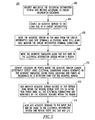
- a process 200 for sensor distribution optimization is shown.
- This process 200 can be applied to an electrical distribution system, such as the example switchgear 2, acoustic signature simulator 4, acoustic sensors 6,8,10,12,14,16, zones 26,28 and circuit interrupters 30,34,36 of Figures 1-3 .
- an electrical distribution system such as the example switchgear 2, acoustic signature simulator 4, acoustic sensors 6,8,10,12,14,16, zones 26,28 and circuit interrupters 30,34,36 of Figures 1-3 .
- couple an acoustic sensor to the load side of a circuit interrupter.
- move the acoustic sensor as far away from the circuit interrupter load side terminals as possible while still being able to monitor the circuit interrupter terminal connection with the acoustic sensor.
- the acoustic simulator moves along the bus bars in the electrical distribution system within a region.
- At least one of the acoustic sensors can be structured to clamp-on an electrical power conductor, such as 60 of Figure 4 .
- an acoustic sensor apparatus 300 includes a clamp, such as the example clamp-on structure 302, for an electrical power conductor, such as the example rectangular power bus bar 304 (shown in phantom line drawing in Figure 6 ).
- the example acoustic sensor apparatus 300 also includes a housing 306 for an acoustic sensor and/or an acoustic generator, such as a low cost piezoelectric element 308 (shown in hidden line drawing in Figure 7 ) housed within the housing 306, and a printed circuit board (PCB) 310 ( Figure 7 ), which can include the example circuit 50 of Figure 4 .
- the housing 306 is clamped onto power bus bar 304 or another power conductor in an electrical system (not shown).
- the exterior of the housing 306 includes an insulation spacer 312, which is coupled to the stainless steel cylindrical canister 318 wherein piezoelectric element 308 (shown in hidden line drawing) is disposed ( Figure 7 ).
- the clamp-on structure 302 is structured to clamp together the insulation spacer 312 and the example power bus bar 304 along with the housing 306.
- the housing 306 can be, for example and without limitation, a metallic housing or an insulative housing having an internal and/or external metal coating structured to provide EMI shielding.
- the metal coating can be, for example and without limitation, a suitable thin film metal coating.
- the example clamp-on structure 302 is disposed through opening 314 of the housing 306.
- the clamp-on structure 302 includes a first insulative clamp portion 316 disposed within the housing 306 and engaging a stainless steel cylindrical canister 318 that houses the piezoelectric element 308 (shown in hidden line drawing) therein, a second insulative clamp portion 320 disposed outside of the housing 306 and being structured to engage the power bus bar 304 ( Figure 6 ), and a threaded coupler, such as the example threaded dowel 322, passing through the first clamp portion 316 and through the housing 306.
- the threaded dowel 322 has a first end and an opposite second threaded end (shown in Figure 8 ) threadably coupled to the second clamp portion 320 (as shown with the second clamp portion 320' in Figure 8 ).
- a rotatable member such as the example circular, insulative fastening knob 324, is coupled to and structured to rotate along the threaded dowel 322 in order to move up or down to pull or push the second clamp portion 320 and clamp or unclamp, respectively, the housing 306, the power bus bar 304 and the second clamp portion 320.
- An insulative screw cap 326 keeps the knob 324 from rotating off the first end of the threaded dowel 322.
- the second clamp portion 320 has an insulative cushion 328 structured to insulatively engage the power bus bar 304.
- the piezoelectric element 308 is within the example 0.5" diameter stainless steel cylindrical canister 318 and is coupled to the bottom of the canister 318, which is opposite the side of the insulative spacer 312 (e.g., a ceramic disk) ( Figure 6 ).
- the insulative spacer 312 e.g., a ceramic disk
- the example acoustic sensor apparatus 300 includes a fault indicator 158, which can be an LED indicator (e.g., without limitation, green flashing for normal operation; red flashing for detection of an electrical conductivity fault operatively associated with the power bus bar 304).
- An on/off switch 330 can enable or disable a power supply (not shown), which can include a battery 332 as shown in Figure 7 .
- the power supply can accept DC power from an external AC/DC or DC/DC power supply (not shown) through DC power input 334.
- the example housing 306 includes a base 336 and a cover 338.
- the base 336 includes posts 340, which engage corresponding structures (not shown) of the cover 338.
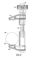
- another clamp-on structure 342 is for a power conductor 344 (shown in phantom line drawing in Figure 8 ) and another acoustic sensor apparatus (not shown), which, except for the clamp-on structure 342, can be the same as or similar to the acoustic sensor apparatus 300 of Figures 6 and 7 .
- the second clamp portion 320' is somewhat different than the second clamp portion 320 of Figure 6 .
- the clamp surface 346 is a concave arcuate surface to accommodate the circular or elliptical cross section of the power conductor 344.
- the second clamp portion 320 of Figure 6 has a flat, generally flat or somewhat convex surface 348 to accommodate the planar surface of the power bus bar 304.
- the clamp-on structure 34 can clamp together a housing, such as 306, the power conductor 344, and optionally an insulative spacer, such as 312.
Landscapes
- Physics & Mathematics (AREA)
- General Physics & Mathematics (AREA)
- Acoustics & Sound (AREA)
- Testing Relating To Insulation (AREA)
- Measurement Of Mechanical Vibrations Or Ultrasonic Waves (AREA)
Abstract
Description
- This application is related to commonly assigned, copending United States Patent Application Serial No.
12/906,244, filed October 18, 2010 12/906,256, filed October 18, 2010 12/906,259, filed October 18,2010 - The disclosed concept pertains generally to acoustic noise induced by electrical conductivity faults and, more particularly, to acoustic sensor systems. The disclosed concept also pertains to acoustic signature simulators. The disclosed concept further pertains to electrical distribution systems.
- Known switchgears, switchboards and motor control centers (MCCs) are custom designed and built. This makes it impossible to have a one-fit-all layout design of an acoustic sensing system for these power distribution systems.
- There is no known cost effective technology and product to detect loose electrical connections in electrical distribution systems. An infrared imaging scan has been widely used to find such loose electrical connections, but this does not provide continuous (e.g., "24-7" or 24 hours a day, seven days a week) detection and monitoring, is limited to detecting only joints within view, and exposes the operator to potentially hazardous conditions.
- Other known products employ temperature sensing at each electrical joint. However, this has not been widely adopted due to cost.
- It is believed to be almost impossible to extract a loose electrical connection signature from both current and voltage due to the relatively small voltage drop across a loose electrical connection (except when this escalates into a major arc fault or arc flash event) except by monitoring voltage drops at each electrical connection.
-
U.S. Patent No. 7,148,696 discloses that an acoustic signature is generated by an arc fault or a glowing contact. An acoustic sensor "listens" directly to signature noise generated by a fault, no matter what type of electrical load is present or in what kind of environment in which the fault is generated. The acoustic noise generated by an arc fault or a glowing contact has an acoustic signal at one or more specific wavelengths that is (are) directly related to either the basic characteristics of, for example, the arc and its resonance frequency or the AC power source modulated frequency and its harmonics. The acoustic signal of an arc fault is detected by an acoustic sensor. A resulting trip signal is sent to a trip mechanism to, for example, trip open separable contacts, in order to interrupt the arc fault. -
U.S. Patent No. 7,411,403 discloses a circuit breaker that detects a loose electrical connection condition of a power circuit. The circuit breaker includes first and second lugs, and first and second acoustic couplers acoustically coupled to the power circuit. An acoustic generator is coupled to the second acoustic coupler and generates a first acoustic signal to the power circuit from the second acoustic coupler. An acoustic sensor is coupled to the first acoustic coupler and has a second acoustic signal which is operatively associated with the loose electrical connection condition. The acoustic sensor outputs a sensed acoustic signal. A circuit cooperates with the acoustic generator to generate the first acoustic signal, input the sensed acoustic signal, and detect the loose electrical connection condition therefrom. The circuit can output a trip signal to a trip mechanism upon detecting an electrical conductivity fault from the sensed acoustic signal. - There is room for improvement in electrical distribution systems.
- These needs and others are met by embodiments of the disclosed concept, which employs acoustic sensors, an acoustic transmitter and/or an acoustic signature simulator to sense noise signals corresponding to electrical conductivity faults and/or to mimic acoustic noise induced by electrical conductivity faults.
- In accordance with one aspect of the disclosed concept, an acoustic sensor system comprises: a first plurality of acoustic sensors; and an acoustic transmitter structured to generate acoustic noise to mimic acoustic noise induced by an electrical conductivity fault, wherein a smaller second number of acoustic sensors of the first plurality of acoustic sensors are structured to identify a plurality of locations in an electrical distribution system having a plurality of electrical joints, in order that the smaller second number of acoustic sensors can monitor all of the plurality of electrical joints of the electrical distribution system.
- At least one of the first plurality of acoustic sensors may be structured to be enabled as the acoustic transmitter with a high voltage pulse circuit.
- The acoustic transmitter may be structured to be moved to a plurality of different locations in the electrical distribution system.
- As another aspect of the disclosed concept, an acoustic signature simulator comprises: a pulse repetition rate control circuit structured to output a plurality of first pulses at one of a number of repetition rates; a voltage pulse generating circuit structured to output a plurality of second voltage pulses responsive to the plurality of first pulses; an acoustic generator structured to output a plurality of mechanical pulses responsive to the plurality of second voltage pulses; and an interface structured to couple the plurality of mechanical pulses to an electrical power conductor.
- As another aspect of the disclosed concept, an electrical distribution system comprises: a plurality of electrical conductors comprising a plurality of electrical joints; a plurality of circuit interrupters, each of the circuit interrupters being electrically interconnected with a number of the plurality of electrical conductors; and a plurality of acoustic sensors, wherein the plurality of electrical conductors form a common bus structure, and wherein each of the plurality of acoustic sensors is coupled to a corresponding one of the plurality of electrical conductors, covers a number of the electrical joints of the corresponding one of the plurality of electrical conductors, and is structured to sense a noise signal corresponding to an electrical conductivity fault of the number of the electrical joints.
- Each of a plurality of the plurality of acoustic sensors may sense a corresponding noise signal. Location of the electrical conductivity fault may be defined by the corresponding noise signal being the strongest noise signal of the plurality of the plurality of acoustic sensors.
- A full understanding of the disclosed concept can be gained from the following description of the preferred embodiments when read in conjunction with the accompanying drawings in which:
-
Figures 1-3 are block diagrams in schematic form of switchgear including an acoustic signature simulator and acoustic sensors in accordance with embodiments of the disclosed concept. -
Figure 4 is a block diagram of the acoustic signature simulator ofFigure 1 . -
Figure 5 is a flowchart of a process for acoustic sensor distribution optimization. -
Figure 6 is a vertical elevation view of an acoustic sensor including a clamp-on structure for a rectangular power bus bar in accordance with another embodiment of the disclosed concept. -
Figure 7 is an isometric view of the acoustic sensor ofFigure 6 except with the cover removed to show internal structures. -
Figure 8 is a vertical elevation view of a clamp-on structure for a power conductor and an acoustic sensor in accordance with another embodiment of the disclosed concept. - As employed herein, the term "number" shall mean one or an integer greater than one (i.e., a plurality).
- As employed herein, the term "acoustic" shall mean one or more sounds that are subsonic, sonic and/or ultrasonic.
- As employed herein, the term "electrical power conductor" shall mean a wire (e.g., solid; stranded; insulated; non-insulated), a copper conductor, an aluminum conductor, a suitable metal conductor, an electrical bus bar, or other suitable material or object that permits an electric current to flow easily.
- As employed herein, the term "electrical joint" shall mean a structure that electrically and mechanically connects a plurality of electrical conductors.
- As employed herein, the term "lug" shall mean a terminal or other electrically conductive fitting to which two or more electrical conductors are electrically and mechanically connected.
- As employed herein, the term "electrical conductivity fault" shall mean an arc fault, or a loose or other intermittent electrical connection of an electrical conductor, an electrical joint and/or a lug that leads to a glowing contact.
- As employed herein, the statement that two or more parts are "connected" or "coupled" together shall mean that the parts are joined together either directly or joined through one or more intermediate parts. Further, as employed herein, the statement that two or more parts are "attached" shall mean that the parts are joined together directly.
- As employed herein, the term "acoustic coupler" shall mean a bolt; an adhesive; a clamp; a fastener; or another suitable coupling mechanism to hold an electrical conductor and an acoustic sensor or an acoustic generator together to allow effective acoustic transmission with or without an electrical connection.
- As employed herein, the term "signature" shall mean something that serves to set apart or identify another thing. For example, an acoustic signature serves to set apart or identify an electrical conductivity fault.
- As employed herein, the term "fastener" shall mean rivets, adhesives, screws, bolts and the combinations of bolts and nuts (e.g., without limitation, lock nuts) and bolts, washers and nuts.
- As employed herein, the term "bolt" shall mean a device or apparatus structured to bolt two or more parts together so as to hold them firmly, such as by bolting an electrical power conductor and a housing including an insulation spacer. A bolt can be, for example, a metal rod or pin for fastening objects together that usually has a head at one end and a screw thread at the other end and is secured by a nut.
- As employed herein, the term "clamp" shall mean a device or apparatus structured to bind or constrict or to press two or more parts together so as to hold them firmly, such as by holding or compressing an electrical power conductor and an insulation spacer. The term "clamp" expressly excludes a fastener.
- The disclosed concept is described in association with, for example and without limitation, three-phase electrical distribution equipment and systems, such as low voltage switchgear, low voltage switch boards, low voltage panel boards, motor control centers and medium voltage switchgear. However, it will be appreciated that the disclosed concept can be employed with a wide range of other applications, such as busway electrical systems for commercial or industrial facilities, aerospace applications, and electric vehicle applications. Also, the disclosed concept is not limited to three-phase applications and can be applied to residential or other single-phase applications. In residential applications, the acoustic signal has a relatively high attenuation rate with relatively small electrical conductors; hence, each acoustic sensor can cover only a relatively short range of the electrical wiring system.
-
Figure 1 shows an electrical distribution system, such asswitchgear 2, including anacoustic signature simulator 4 andacoustic sensors Figure 4 , the exampleacoustic signature simulator 2 includes an acoustic generator, such as a piezoelectricacoustic transmitter 18, to generate anacoustic signal 20 that mimics an acoustic signal of an electrical conductivity fault, such as an arc fault, a glowing contact or a loose electrical connection that leads to a glowing contact, such as 22 or 24 ofFigures 1 and2 . Alternatively, any suitable electrical, mechanical or electro-mechanical acoustic generator, or magnetostrictive device can be employed to simulate acoustic noise generated by an electrical conductivity fault (e.g., the generated acoustic signal wavelet resembles that induced by an electrical conductivity fault with a repetitive rate of a power frequency or its harmonics). As will be explained, the example piezoelectricacoustic transmitter 18 can be coupled to different locations of an electrical distribution system, such as theexample switchgear 2, to determine where acoustic sensors, such as 6,8,10,12,14,16, should be positioned, in order to provide complete detection coverage for looseelectrical connections respective zones - In the
example switchgear 2, circuit interrupters, such ascircuit breakers switchgear 2 into acoustically isolated zones, such as 26,28. - The
example circuit breaker 34 is a three-pole circuit breaker. Theexample circuit breaker 30 is a six-pole circuit breaker with two poles paralleled per phase. However, it will be appreciated that a three-pole circuit breaker could be employed. - As will be explained, the example piezoelectric
acoustic transmitter 18 ofFigure 4 can be part of a suitable acoustic sensor (e.g., without limitation, a piezoelectric sensor), such asacoustic sensors example switchgear 2, each phase employs a corresponding piezoelectric acoustic sensor. So, for instance, for a three-phase system, there are three acoustic sensors, one for each phase. - In
Figure 1 , the looseelectrical connection 24 is detected by sensor 8 in zone 28 (zone #2). Similarly, the acoustic signal 20 (Figure 4 ) fromacoustic signature simulator 4 can also detected by sensor 8 inzone 28. However, the looseelectrical connection 22 is not detected by sensor 8 due to blocking bycircuit breaker 30.Sensors electrical connection 24 due to the attenuation of the acoustic signal, or may not be able to confirm that the looseelectrical connection 24 is in zone 28 (zone #2) due to the relatively low level of noise detected by thosesensors zone 28. -
Figures 2 and3 show variations of how theexample switchgear 2 works in terms of thesimulator 4, theexample zones acoustic sensors 6,8 and the circuit breaker 30 (that provides acoustic isolation). This can either use thesimulator 4 to optimize locations of thesensors sensors 6,8 to detect locations of looseelectrical connections - In
Figure 2 , thesimulator 4 is moved to a different location; otherwise, theswitchgear 2 is the same as theswitchgear 2 shown inFigure 1 . The looseelectrical connection 22 is detected bysensor 6 in zone 26 (zone #1). However, the looseelectrical connection 22 is not detected bysensors circuit breaker 30, and is not detected bysensors circuit breakers - In
Figure 3 , thesimulator 4 is moved to a different location; otherwise, theswitchgear 2 is the same as theswitchgear 2 shown inFigure 1 . The location of looseelectrical connection 38 can be "pinpointed" through "triangulation". Looseelectrical connection 38 can be detected and located by comparing measured noise values bysensors sensor 16 will measure the strongest noise signal, followed by sensor 8 and then bysensor 14. Hence, the looseelectrical connection 38 can be confirmed to be part of the common bus structure formed by three-phase buses respective sensors sensor 16 onbus 44 rather thansensors 8 or 14 onrespective buses -
Figure 4 shows the exampleacoustic signature simulator 4 ofFigures 1-3 . Thesimulator 4 including thecircuit 50 can be powered by anexternal power supply 46 through apower switch 48, as shown. For example, the power lines may not be energized during testing. As a non-limiting example, a battery can be employed as thepower supply 46. Thecircuit 50 provides a number of repetition rates ofelectronic pulses 52. Thepulses 52 trigger a voltagepulse generating circuit 54 at a number of suitable voltages (e.g., without limitation, 150V; 400V; any suitable voltage to provide a suitable acoustic pulse amplitude). Theoutput voltage pulses 56 drive the examplepiezoelectric element 18 to generatemechanical pulses 57 through a suitable interface, such as insulation spacer 58 (e.g., without limitation, a ceramic disk), onto a suitable electrical power conductor, such as bus bar orelectrical cable 60, in order to simulate a plurality ofacoustic signals 20 induced by loose electrical connections (e.g., without limitation, over-heated electrical joints (not shown, but seeelectrical joints 61 and looseelectrical connections Figures 1-3 )). Theexample insulation spacer 58 is disposed between the example piezoelectric element 18 (or a piezoelectric element housing (not shown)) and theexample bus bar 60. The optional "preload" 62 of the example piezoelectric element 18 (or of a corresponding acoustic sensor) optionally compresses thepiezoelectric element 18 under pressure in its assembly. Hence, the examplepiezoelectric element 18 can either be preloaded to theexample insulation spacer 58, or is not preloaded thereto. Thecircuit 50 can include aselection circuit 64 that selects one of a plurality of different high voltages, and acontrol circuit 66 that provides theelectronic pulses 52 at a suitable repetition rate, such as, for example, that of a line frequency. - The example
acoustic signature simulator 4 includes the pulse repetitionrate control circuit 66 structured to output thefirst pulses 52 at one of a number of repetition rates, the voltagepulse generating circuit 54 structured to output thesecond voltage pulses 56 responsive to thefirst pulses 52, the examplepiezoelectric element 18 structured to output themechanical pulses 57 responsive to thesecond voltage pulses 56, and theinterface 58 structured to couple themechanical pulses 57 to theelectrical power conductor 60. - The voltage
pulse generating circuit 54 can be structured to output thesecond voltage pulses 56 at a plurality of different voltages (e.g., without limitation, 150V, 400V, any suitable voltage). For example, this can simulate an acoustic signal induced by a loose connection at different locations, different current levels, or even just a variation of acoustic signals generated by the same loose connection. This can include multiple voltages at the same time to simulate the variation of an acoustic signal from a loose electrical connection or just one selected voltage. - The pulse repetition
rate control circuit 66 can be structured to select one of a plurality of different repetition rates (e.g., without limitation, corresponding to 50 Hz, 60 Hz, 85 Hz, 120 Hz, 135 Hz, 400 Hz, harmonics and sub-harmonics of the line frequency, any suitable frequency). This can be employed to, for example and without limitation, test an acoustic sensor's detection capability and nuisance detection performance. This can permit a wide range of power line applications (e.g., 60 Hz in the United States; 50 Hz in Europe and Asia; 400 Hz for aerospace applications). Also, the selection of various repetition rates permit testing whether an acoustic sensor can detect and use no frequency other than the power line frequency and its harmonics in order to make sure that it does not cause nuisance tripping. - As shown in
Figure 4 , the example acousticpiezoelectric transmitter 18 can be structured to generate acoustic pulses conducting through electrical power conductors, such as bus bars and/or power cables, at a frequency from about 10 kHz to about 40 kHz modulated by a line frequency. The line frequency can be selected from the group consisting of about 50 Hz, about 60 Hz, about 400 Hz, and harmonics or sub-harmonics of the line frequency. - As shown with respect to
Figures 1-3 , theacoustic signature simulator 4 can be moved to a plurality of different locations, such as theexample zones switchgear 2. Alternatively, any number of the exampleacoustic sensors voltage pulse circuit 54 ofFigure 4 . When the piezoelectric element (not shown, but see the examplepiezoelectric element 18 ofFigure 4 ) of the corresponding acoustic sensor experiences stress and strain, it generates a voltage output. In this case, it is employed as a sensor. However, when a voltage, such as 56, is applied across the examplepiezoelectric element 18, the dimension of the example piezoelectric element changes. This characteristic can be used as an acoustic transmitter or generator. For example and without limitation, the example high voltagepulse generating circuit 54 can be integrated into the electronic circuitry of theacoustic sensors acoustic signal 20. - Referring again to
Figure 1 , anacoustic sensor system 68 includes a first plurality ofacoustic sensors example piezoelectric transmitter 18 ofFigure 4 , structured to generate theacoustic noise 20 to mimic acoustic noise induced by an electrical conductivity fault, such as 22, 24 or 38 (Figure 3 ). A smaller second number of the acoustic sensors, such as for example and without limitation oneacoustic sensor 6, one acoustic sensor 8, or threeacoustic sensors switchgear 2, in order that such second number of acoustic sensors can monitor all of the plurality ofelectrical joints 61 thereof. - As shown in
Figure 3 , the exampleacoustic sensors switchgear 2. Each of theacoustic sensors electrical joints 61 of a correspondingzone switchgear 2. For example, thesensor 14 can cover the joint 61 of thezone 70, and thesensor 16 can cover the joints 61 (shown inFigure 1 ) of the zone 72. Theexample zone 28 is defined by thecircuit interrupters example zone 26 offigure 1 is defined by thecircuit interrupter 30 that blocks acoustic propagation. - In order to provide complete detection coverage of electrical conductivity faults and their zone location in electrical distribution systems, such as, for example, switchgears, MCCs, switchboards and panel boards, the disclosed concept allows effective and quick determination of where acoustic sensors should be located in a new electrical distribution system. The disclosed acoustic signature simulator generates a simulated acoustic signal that has the same characteristics as that of glowing contacts and is easy to move around in the electrical distribution system.
- Referring to
Figure 5 , aprocess 200 for sensor distribution optimization is shown. Thisprocess 200 can be applied to an electrical distribution system, such as theexample switchgear 2,acoustic signature simulator 4,acoustic sensors zones circuit interrupters Figures 1-3 . First, at 202, identify and divide the electrical distribution system into regions according to circuit interrupter locations. Then, at 204, couple an acoustic sensor to the load side of a circuit interrupter. Next, at 206, move the acoustic sensor as far away from the circuit interrupter load side terminals as possible while still being able to monitor the circuit interrupter terminal connection with the acoustic sensor. Then, at 208, move the acoustic simulator along the bus bars in the electrical distribution system within a region. Next, at 210, identify locations or points where the acoustic sensor cannot effectively detect loose electrical connection signals generated by the acoustic simulator; and define those locations and points as boundaries of a detection zone for the acoustic sensor. Then, at 212, add another acoustic sensor outside of the defined zone within the region; andrepeat step 210 to define new zones until all the electrical connections are monitored by the acoustic sensors within that region. Finally, at 214, also add acoustic sensors to the input bus bar or cable to the electrical distribution system and repeatsteps - As will be discussed in connection with
Figures 6-8 , at least one of the acoustic sensors, such as 6,8,10,12,14,16 ofFigure 1 , and/or thesimulator 4 ofFigure 1 , can be structured to clamp-on an electrical power conductor, such as 60 ofFigure 4 . - Referring to
Figures 6 and7 , anacoustic sensor apparatus 300 includes a clamp, such as the example clamp-onstructure 302, for an electrical power conductor, such as the example rectangular power bus bar 304 (shown in phantom line drawing inFigure 6 ). The exampleacoustic sensor apparatus 300 also includes ahousing 306 for an acoustic sensor and/or an acoustic generator, such as a low cost piezoelectric element 308 (shown in hidden line drawing inFigure 7 ) housed within thehousing 306, and a printed circuit board (PCB) 310 (Figure 7 ), which can include theexample circuit 50 ofFigure 4 . Thehousing 306 is clamped ontopower bus bar 304 or another power conductor in an electrical system (not shown). - As shown in
Figure 6 , the exterior of thehousing 306 includes aninsulation spacer 312, which is coupled to the stainless steelcylindrical canister 318 wherein piezoelectric element 308 (shown in hidden line drawing) is disposed (Figure 7 ). The clamp-onstructure 302 is structured to clamp together theinsulation spacer 312 and the examplepower bus bar 304 along with thehousing 306. - The
housing 306 can be, for example and without limitation, a metallic housing or an insulative housing having an internal and/or external metal coating structured to provide EMI shielding. The metal coating can be, for example and without limitation, a suitable thin film metal coating. - As is best shown in
Figure 7 , the example clamp-onstructure 302 is disposed throughopening 314 of thehousing 306. The clamp-onstructure 302 includes a firstinsulative clamp portion 316 disposed within thehousing 306 and engaging a stainless steelcylindrical canister 318 that houses the piezoelectric element 308 (shown in hidden line drawing) therein, a secondinsulative clamp portion 320 disposed outside of thehousing 306 and being structured to engage the power bus bar 304 (Figure 6 ), and a threaded coupler, such as the example threadeddowel 322, passing through thefirst clamp portion 316 and through thehousing 306. The threadeddowel 322 has a first end and an opposite second threaded end (shown inFigure 8 ) threadably coupled to the second clamp portion 320 (as shown with the second clamp portion 320' inFigure 8 ). - A rotatable member, such as the example circular,
insulative fastening knob 324, is coupled to and structured to rotate along the threadeddowel 322 in order to move up or down to pull or push thesecond clamp portion 320 and clamp or unclamp, respectively, thehousing 306, thepower bus bar 304 and thesecond clamp portion 320. Aninsulative screw cap 326 keeps theknob 324 from rotating off the first end of the threadeddowel 322. - Preferably, the
second clamp portion 320 has aninsulative cushion 328 structured to insulatively engage thepower bus bar 304. - The
piezoelectric element 308 is within the example 0.5" diameter stainless steelcylindrical canister 318 and is coupled to the bottom of thecanister 318, which is opposite the side of the insulative spacer 312 (e.g., a ceramic disk) (Figure 6 ). - As shown in
Figure 7 , the exampleacoustic sensor apparatus 300 includes afault indicator 158, which can be an LED indicator (e.g., without limitation, green flashing for normal operation; red flashing for detection of an electrical conductivity fault operatively associated with the power bus bar 304). An on/off switch 330 can enable or disable a power supply (not shown), which can include abattery 332 as shown inFigure 7 . Also, the power supply can accept DC power from an external AC/DC or DC/DC power supply (not shown) through DC power input 334. - As can be seen from
Figures 6 and7 , theexample housing 306 includes abase 336 and acover 338. Thebase 336 includesposts 340, which engage corresponding structures (not shown) of thecover 338. - Referring to
Figure 8 , another clamp-on structure 342 is for a power conductor 344 (shown in phantom line drawing inFigure 8 ) and another acoustic sensor apparatus (not shown), which, except for the clamp-on structure 342, can be the same as or similar to theacoustic sensor apparatus 300 ofFigures 6 and7 . The second clamp portion 320' is somewhat different than thesecond clamp portion 320 ofFigure 6 . In particular, theclamp surface 346 is a concave arcuate surface to accommodate the circular or elliptical cross section of thepower conductor 344. Conversely, thesecond clamp portion 320 ofFigure 6 has a flat, generally flat or somewhatconvex surface 348 to accommodate the planar surface of thepower bus bar 304. In this example, no insulative cushion is employed since electrical cables usually have insulative sleeves thereon. Otherwise, the clamp-on structure 342, like the clamp-onstructure 302, can clamp together a housing, such as 306, thepower conductor 344, and optionally an insulative spacer, such as 312. - While specific embodiments of the disclosed concept have been described in detail, it will be appreciated by those skilled in the art that various modifications and alternatives to those details could be developed in light of the overall teachings of the disclosure. Accordingly, the particular arrangements disclosed are meant to be illustrative only and not limiting as to the scope of the disclosed concept which is to be given the full breadth of the claims appended and any and all equivalents thereof.
-
- 1. An acoustic sensor system comprising:
- a first plurality of acoustic sensors; and
- an acoustic transmitter structured to generate acoustic noise to mimic acoustic noise induced by an electrical conductivity fault,
- wherein a smaller second number of acoustic sensors of said first plurality of acoustic sensors are structured to identify a plurality of locations in an electrical distribution system having a plurality of electrical joints, in order that said smaller second number of acoustic sensors can monitor all of the plurality of electrical joints of said electrical distribution system.
- 2. The acoustic sensor system of 1 wherein said acoustic transmitter is a piezoelectric transmitter.
- 3. The acoustic sensor system of 1 wherein said smaller second number of acoustic sensors are a second plurality of acoustic sensors coupled to a plurality of bus bars at the plurality of locations in the electrical distribution system having the plurality of electrical joints, in order that each of said second plurality of acoustic sensors covers a number of the electrical joints of a corresponding zone of said electrical distribution system.
- 4. The acoustic sensor system of 3 wherein the corresponding zone of said electrical distribution system is defined by a number of circuit interrupters that block acoustic propagation.
- 5. The acoustic sensor system of 1 wherein at least one of said first plurality of acoustic sensors is structured to be enabled as said acoustic transmitter with a high voltage pulse circuit.
- 6. The acoustic sensor system of 1 wherein said acoustic transmitter is structured to be moved to a plurality of different locations in said electrical distribution system.
- 7. The acoustic sensor system of 1 wherein said acoustic transmitter is structured to generate acoustic pulses in an electrical power conductor of said electrical distribution system at a frequency about 10 kHz to about 40 kHz modulated by a line frequency.
- 8. The acoustic sensor system of 7 wherein said line frequency is selected from the group consisting of about 50 Hz, about 60 Hz, about 400 Hz, and harmonics or sub-harmonics of said line frequency.
- 9. An acoustic signature simulator comprising:
- a pulse repetition rate control circuit structured to output a plurality of first pulses at one of a number of repetition rates;
- a voltage pulse generating circuit structured to output a plurality of second voltage pulses responsive to said plurality of first pulses;
- an acoustic generator structured to output a plurality of mechanical pulses responsive to said plurality of second voltage pulses; and
- an interface structured to couple said plurality of mechanical pulses to an electrical power conductor.
- 10. The acoustic signature simulator of 9 wherein said acoustic generator is preloaded to said interface.
- 11. The acoustic signature simulator of 9 wherein said acoustic generator is not preloaded to said interface.
- 12. The acoustic signature simulator of 9 wherein said voltage pulse generating circuit is further structured to output said plurality of second voltage pulses at a plurality of different voltages.
- 13. The acoustic signature simulator of 9 wherein said pulse repetition rate control circuit and said voltage pulse generating circuit are both structured to be powered by a power supply external to said acoustic signature simulator.
- 14. The acoustic signature simulator of 9 wherein said interface comprises an insulation spacer structured to be disposed between said acoustic generator and said electrical power conductor.
- 15. The acoustic signature simulator of 14 wherein said insulation spacer is a ceramic disk.
- 16. The acoustic signature simulator of 9 wherein said electrical power conductor is an electrical bus bar.
- 17. The acoustic signature simulator of 9 wherein said electrical power conductor is an electrical cable.
- 18. The acoustic signature simulator of 9 wherein said plurality of mechanical pulses are structured to simulate a plurality of acoustic signals induced by a loose electrical connection.
- 19. The acoustic signature simulator of 9 wherein said pulse repetition rate control circuit is further structured to select one of a plurality of different repetition rates as said one of said number of repetition rates.
- 20. The acoustic signature simulator of 19 wherein said one of said plurality of different repetition rates is selected from the group consisting of rates corresponding to a line frequency, harmonics of said line frequency, and sub-harmonics of said line frequency.
- 21. The acoustic signature simulator of 9 wherein said one of said number of repetition rates corresponds to a line frequency modulating a plurality of acoustic pulses conducting through said electrical power conductor at a frequency from about 10 kHz to about 40 kHz.
- 22. An electrical distribution system comprising:
- a plurality of electrical conductors comprising a plurality of electrical joints;
- a plurality of circuit interrupters, each of said circuit interrupters being electrically interconnected with a number of said plurality of electrical conductors; and
- a plurality of acoustic sensors,
- wherein said plurality of electrical conductors form a common bus structure, and
- wherein each of said plurality of acoustic sensors is coupled to a corresponding one of said plurality of electrical conductors, covers a number of the electrical joints of the corresponding one of said plurality of electrical conductors, and is structured to sense a noise signal corresponding to an electrical conductivity fault of said number of the electrical joints.
- 23. The electrical distribution system of 22 wherein each of a plurality of said plurality of acoustic sensors senses a corresponding noise signal; and wherein location of the electrical conductivity fault is defined by the corresponding noise signal being the strongest noise signal of said plurality of said plurality of acoustic sensors.
- 24. The electrical distribution system of 22 wherein a number of said plurality of acoustic sensors are structured to clamp-on a number of said plurality of electrical conductors.
- 25. The acoustic sensor system of 1 wherein said acoustic transmitter is structured to clamp-on an electrical conductor of said electrical distribution system.
-
- 2
- electrical distribution system, such as switchgear
- 4
- acoustic signature simulator
- 6
- acoustic sensor
- 8
- acoustic sensor
- 10
- acoustic sensor
- 12
- acoustic sensor
- 14
- acoustic sensor
- 16
- acoustic sensor
- 18
- acoustic generator, such as a piezoelectric acoustic transmitter
- 20
- acoustic signal
- 22
- loose electrical connection
- 24
- loose electrical connection
- 26
- zone
- 28
- zone
- 30
- circuit interrupter, such as circuit breaker
- 34
- circuit breaker
- 36
- circuit breaker
- 38
- loose electrical connection
- 40
- three-phase bus
- 42
- three-phase bus
- 44
- three-phase bus
- 46
- external power supply
- 48
- power switch
- 50
- circuit
- 52
- number of repetition rates of electronic pulses
- 54
- voltage pulse generating circuit
- 56
- output voltage pulses
- 57
- plurality of mechanical pulses
- 58
- insulation spacer
- 60
- electrical power conductor, such as bus bar
- 61
- electrical joints
- 62
- optional "preload"
- 64
- selection circuit
- 66
- control circuit
- 68
- acoustic sensor system
- 70
- zone
- 72
- zone
- 200
- process
- 202
- step
- 204
- step
- 206
- step
- 208
- step
- 210
- step
- 212
- step
- 214
- step
- 300
- acoustic sensor apparatus
- 302
- clamp, such as the example clamp-on structure
- 304
- electrical power conductor, such as the example rectangular power bus
- 306
- housing
- 308
- acoustic sensor and/or an acoustic generator, such as a low cost piezoelectric element
- 310
- printed circuit board (PCB)
- 312
- insulation spacer
- 314
- opening
- 316
- first clamp portion
- 318
- stainless steel cylindrical canister
- 320
- second clamp portion
- 320'
- second clamp portion
- 322
- threaded dowel
- 324
- circular, insulative fastening knob
- 326
- insulative screw cap
- 328
- insulative cushion
- 330
- on/off switch
- 332
- battery
- 334
- DC power input
- 336
- base
- 338
- cover
- 340
- posts
- 342
- clamp-on structure
- 344
- power conductor
- 346
- clamp surface
- 348
- surface
Claims (15)
- An acoustic sensor system (68) comprising:a first plurality of acoustic sensors (6,8,10,12,14,16); andan acoustic transmitter (18) structured to generate acoustic noise (20) to mimic acoustic noise induced by an electrical conductivity fault (22,24,38),wherein a smaller second number of acoustic sensors (6;8;8,14,16) of said first plurality of acoustic sensors are structured to identify a plurality of locations (26,28,70,72) in an electrical distribution system (2) having a plurality of electrical joints (61), in order that said smaller second number of acoustic sensors can monitor all of the plurality of electrical joints of said electrical distribution system.
- The acoustic sensor system (68) of Claim 1 wherein said acoustic transmitter is a piezoelectric transmitter (18).
- The acoustic sensor system (68) of Claim 1 wherein said smaller second number of acoustic sensors are a second plurality of acoustic sensors (8,14,16) coupled to a plurality of bus bars (40,42,44) at the plurality of locations in the electrical distribution system having the plurality of electrical joints, in order that each of said second plurality of acoustic sensors covers a number of the electrical joints of a corresponding zone (28,70,72) of said electrical distribution system,
wherein the corresponding zone of said electrical distribution system may preferably be defined by a number of circuit interrupters (30,34,36) that block acoustic propagation. - The acoustic sensor system (68) of Claim 1 wherein at least one of said first plurality of acoustic sensors is structured to be enabled as said acoustic transmitter with a high voltage pulse circuit (54), and/or
wherein preferably said acoustic transmitter is structured to be moved to a plurality of different locations in said electrical distribution system, and/or
wherein preferably said acoustic transmitter is structured to generate acoustic pulses in an electrical power conductor of said electrical distribution system at a frequency about 10 kHz to about 40 kHz modulated by a line frequency,
wherein said line frequency may preferably be selected from the group consisting of about 50 Hz, about 60 Hz, about 400 Hz, and harmonics or sub-harmonics of said line frequency. - An acoustic signature simulator (4) comprising:a pulse repetition rate control circuit (66) structured to output a plurality of first pulses (52) at one of a number of repetition rates;a voltage pulse generating circuit (54) structured to output a plurality of second voltage pulses (56) responsive to said plurality of first pulses;an acoustic generator (18) structured to output a plurality of mechanical pulses (57) responsive to said plurality of second voltage pulses; andan interface (58) structured to couple said plurality of mechanical pulses to an electrical power conductor (60).
- The acoustic signature simulator (4) of Claim 5 wherein said acoustic generator is preloaded (62) to said interface, or
is not preloaded (62) to said interface. - The acoustic signature simulator (4) of Claim 5 or 6, wherein said voltage pulse generating circuit is further structured to output said plurality of second voltage pulses at a plurality of different voltages.
- The acoustic signature simulator (4) of any one of Claims 5 to 7, wherein said pulse repetition rate control circuit and said voltage pulse generating circuit are both structured to be powered by a power supply (46) external to said acoustic signature simulator (4).
- The acoustic signature simulator (4) of any one of Claims 5 to 8, wherein said interface comprises an insulation spacer (58) structured to be disposed between said acoustic generator and said electrical power conductor,
wherein said insulation spacer may preferably be a ceramic disk (58). - The acoustic signature simulator (4) of any one of Claims 5 to 9, wherein said electrical power conductor is an electrical bus bar (60), or an electrical cable (60).
- The acoustic signature simulator (4) of any one of Claims 5 to 10, wherein said plurality of mechanical pulses (57) are structured to simulate a plurality of acoustic signals induced by a loose electrical connection (22,24,38).
- The acoustic signature simulator (4) of any one of Claims 5 to 11, wherein said pulse repetition rate control circuit is further structured to select one of a plurality of different repetition rates as said one of said number of repetition rates, wherein said one of said plurality of different repetition rates is selected from the group consisting of rates corresponding to a line frequency, harmonics of said line frequency, and sub-harmonics of said line frequency.
- The acoustic signature simulator (4) of any one of Claims 5 to 11, wherein said one of said number of repetition rates corresponds to a line frequency modulating a plurality of acoustic pulses conducting through said electrical power conductor at a frequency from about 10 kHz to about 40 kHz.
- An electrical distribution system (2) comprising:a plurality of electrical conductors (40,42,44) comprising a plurality of electrical joints (61);a plurality of circuit interrupters (30,34,36), each of said circuit interrupters being electrically interconnected with a number of said plurality of electrical conductors; anda plurality of acoustic sensors (8,14,16),wherein said plurality of electrical conductors form a common bus structure, andwherein each of said plurality of acoustic sensors is coupled to a corresponding one of said plurality of electrical conductors, covers a number of the electrical joints of the corresponding one of said plurality of electrical conductors, and is structured to sense a noise signal corresponding to an electrical conductivity fault of said number of the electrical joints.
- The electrical distribution system (2) of Claim 14 wherein each of a plurality of said plurality of acoustic sensors (8,14,16) senses a corresponding noise signal; and wherein location of the electrical conductivity fault is defined by the corresponding noise signal being the strongest noise signal of said plurality of said plurality of acoustic sensors,
wherein a number of said plurality of acoustic sensors may preferably be structured to clamp-on a number of said plurality of electrical conductors, and/or
wherein said acoustic transmitter (18) is structured to clamp-on an electrical conductor of said electrical distribution system.
Applications Claiming Priority (1)
| Application Number | Priority Date | Filing Date | Title |
|---|---|---|---|
| US12/906,258 US8434367B2 (en) | 2010-10-18 | 2010-10-18 | Acoustic sensor system, acoustic signature simulator, and electrical distribution system |
Publications (3)
| Publication Number | Publication Date |
|---|---|
| EP2442121A2 true EP2442121A2 (en) | 2012-04-18 |
| EP2442121A3 EP2442121A3 (en) | 2013-01-02 |
| EP2442121B1 EP2442121B1 (en) | 2016-06-15 |
Family
ID=45406356
Family Applications (1)
| Application Number | Title | Priority Date | Filing Date |
|---|---|---|---|
| EP11008369.8A Not-in-force EP2442121B1 (en) | 2010-10-18 | 2011-10-18 | Acoustic sensor system, acoustic signature simulator, and electrical distribution system |
Country Status (4)
| Country | Link |
|---|---|
| US (2) | US8434367B2 (en) |
| EP (1) | EP2442121B1 (en) |
| CN (1) | CN102539951B (en) |
| CA (1) | CA2755187A1 (en) |
Cited By (5)
| Publication number | Priority date | Publication date | Assignee | Title |
|---|---|---|---|---|
| CN103499776A (en) * | 2013-09-03 | 2014-01-08 | 华北电力大学(保定) | Power transmission and transformation equipment fault routing inspection core system based on ultrasonic waves and infrared thermal images |
| WO2014109817A1 (en) * | 2013-01-08 | 2014-07-17 | Eaton Corporation | Detection and location of electrical connections having a micro-interface abnormality in an electrical system |
| CN104333733A (en) * | 2014-10-17 | 2015-02-04 | 天津全华时代航天科技发展有限公司 | UAV airborne computer system |
| FR3079934A1 (en) * | 2018-04-06 | 2019-10-11 | Hager Controls | METHOD FOR DETECTION OF AN EVENT ARISING AT AN ELECTRICAL DISTRIBUTION PANEL. |
| US11480600B2 (en) | 2017-04-25 | 2022-10-25 | IRISS Holdings, Inc. | Panel for audible monitoring of electrical components and the detection of electrical faults |
Families Citing this family (17)
| Publication number | Priority date | Publication date | Assignee | Title |
|---|---|---|---|---|
| US8665666B2 (en) * | 2010-10-18 | 2014-03-04 | Eaton Corporation | Acoustic apparatus and acoustic sensor apparatus including a fastener |
| US8434367B2 (en) * | 2010-10-18 | 2013-05-07 | Eaton Corporation | Acoustic sensor system, acoustic signature simulator, and electrical distribution system |
| CA2885185A1 (en) * | 2012-10-12 | 2014-04-17 | Schweitzer Engineering Laboratories, Inc. | Coordinated high-impedance fault detection systems and methods |
| JP6054219B2 (en) * | 2013-03-19 | 2016-12-27 | 株式会社東芝 | Ultrasonic bonding equipment |
| US20150102824A1 (en) * | 2013-10-11 | 2015-04-16 | General Electric Company | Locating loose connections in an electrical circuit |
| US9933285B2 (en) * | 2014-03-21 | 2018-04-03 | Eaton Intelligent Power Limited | Piezoelectric sensor assembly, and sensor attachment assembly and electrical system employing same |
| CN104898013A (en) * | 2015-06-09 | 2015-09-09 | 北京联合大学 | Method and system for diagnosing circuit fault based on acoustical measurement |
| US9952184B2 (en) * | 2015-12-17 | 2018-04-24 | Schneider Electric It Corporation | Ultrasonic monitoring of electrical connections |
| CN109073704A (en) | 2017-03-02 | 2018-12-21 | 罗斯蒙特公司 | Trend function for shelf depreciation |
| US20190041364A1 (en) * | 2017-08-02 | 2019-02-07 | United States Of America As Represented By The Secretary Of The Navy | System and Method for Detecting Failed Electronics Using Acoustics |
| US11067639B2 (en) | 2017-11-03 | 2021-07-20 | Rosemount Inc. | Trending functions for predicting the health of electric power assets |
| FR3075394B1 (en) * | 2017-12-14 | 2020-10-30 | Commissariat Energie Atomique | PROCESS FOR DETECTION OF A MALFUNCTIONING OF AN ACOUSTIC SENSOR COUPLED TO AN ELECTROCHEMICAL GENERATOR AND DEVICE IMPLEMENTING THIS PROCEDURE |
| US10794736B2 (en) | 2018-03-15 | 2020-10-06 | Rosemount Inc. | Elimination of floating potential when mounting wireless sensors to insulated conductors |
| US11181570B2 (en) | 2018-06-15 | 2021-11-23 | Rosemount Inc. | Partial discharge synthesizer |
| US10833531B2 (en) | 2018-10-02 | 2020-11-10 | Rosemount Inc. | Electric power generation or distribution asset monitoring |
| US11313895B2 (en) | 2019-09-24 | 2022-04-26 | Rosemount Inc. | Antenna connectivity with shielded twisted pair cable |
| CN112517361B (en) * | 2020-11-30 | 2022-06-03 | 国网山西省电力公司朔州供电公司 | High-sensitivity multi-band combined type air-coupled ultrasonic transducer and preparation method thereof |
Citations (2)
| Publication number | Priority date | Publication date | Assignee | Title |
|---|---|---|---|---|
| US7148696B2 (en) | 2005-01-12 | 2006-12-12 | Eaton Corporation | Electrical switching apparatus and method including fault detection employing acoustic signature |
| US7411403B2 (en) | 2005-05-10 | 2008-08-12 | Eaton Corporation | Electrical switching apparatus and method employing active acoustic sensing to detect an electrical conductivity fault of a power circuit |
Family Cites Families (15)
| Publication number | Priority date | Publication date | Assignee | Title |
|---|---|---|---|---|
| FR1181357A (en) | 1956-08-21 | 1959-06-15 | British Insulated Callenders | Improvements in the localization of electrical faults in insulated electrical conductors |
| DE2641047A1 (en) | 1976-09-11 | 1978-03-16 | Licentia Gmbh | Locating arcing breakdowns in separate sealed cable sections - using a fully independent indicator for each section |
| SE9600989D0 (en) * | 1996-03-15 | 1996-03-15 | Abb Research Ltd | Method and apparatus for space charge measurement in cables using a pulsed electroacoustic method |
| US5821430A (en) * | 1997-02-28 | 1998-10-13 | Southwest Research Institute | Method and apparatus for conducting in-situ nondestructive tensile load measurements in cables and ropes |
| US6114971A (en) * | 1997-08-18 | 2000-09-05 | X-Cyte, Inc. | Frequency hopping spread spectrum passive acoustic wave identification device |
| US6300767B1 (en) | 1998-11-30 | 2001-10-09 | General Electric Company | System and apparatus for predicting failure in insulated systems |
| SG111012A1 (en) | 2000-02-28 | 2005-05-30 | Mitsubishi Electric Corp | Failure determining apparatus of gas-insulated electrical appliance |
| AUPQ672300A0 (en) * | 2000-04-05 | 2000-05-04 | Nu-Lec Industries Pty Limited | Isolating circuit breaker and circuit protection arrangement |
| US6377184B1 (en) | 2000-04-11 | 2002-04-23 | Gary A. Minker | Transmission line safety monitoring system |
| US6810743B2 (en) * | 2001-08-01 | 2004-11-02 | The United States Of America As Represented By The Administrator Of The National Aeronautics And Space Adminstration | Non-destructive evaluation of wire insulation and coatings |
| US6734682B2 (en) * | 2002-03-05 | 2004-05-11 | Eaton Corporation | Testing device for detecting and locating arc faults in an electrical system |
| US7503219B2 (en) * | 2002-09-26 | 2009-03-17 | Siemens Aktiengesellschaft | Monitoring and diagnosing a technical installation using purely mechanically activated signaling means |
| CN1821795A (en) * | 2006-03-29 | 2006-08-23 | 保定天威集团有限公司 | Method and its device for detecting discharge fault position of high voltage electric equipment |
| US7403129B2 (en) * | 2006-05-10 | 2008-07-22 | Eaton Corporation | Electrical switching apparatus and method employing acoustic and current signals to distinguish between parallel and series arc faults |
| US8434367B2 (en) * | 2010-10-18 | 2013-05-07 | Eaton Corporation | Acoustic sensor system, acoustic signature simulator, and electrical distribution system |
-
2010
- 2010-10-18 US US12/906,258 patent/US8434367B2/en not_active Expired - Fee Related
-
2011
- 2011-10-18 CA CA2755187A patent/CA2755187A1/en not_active Abandoned
- 2011-10-18 EP EP11008369.8A patent/EP2442121B1/en not_active Not-in-force
- 2011-10-18 CN CN201110317430.2A patent/CN102539951B/en not_active Expired - Fee Related
-
2013
- 2013-04-01 US US13/854,523 patent/US8635914B2/en not_active Expired - Fee Related
Patent Citations (2)
| Publication number | Priority date | Publication date | Assignee | Title |
|---|---|---|---|---|
| US7148696B2 (en) | 2005-01-12 | 2006-12-12 | Eaton Corporation | Electrical switching apparatus and method including fault detection employing acoustic signature |
| US7411403B2 (en) | 2005-05-10 | 2008-08-12 | Eaton Corporation | Electrical switching apparatus and method employing active acoustic sensing to detect an electrical conductivity fault of a power circuit |
Cited By (9)
| Publication number | Priority date | Publication date | Assignee | Title |
|---|---|---|---|---|
| WO2014109817A1 (en) * | 2013-01-08 | 2014-07-17 | Eaton Corporation | Detection and location of electrical connections having a micro-interface abnormality in an electrical system |
| US9304159B2 (en) | 2013-01-08 | 2016-04-05 | Eaton Corporation | Detection and location of electrical connections having a micro-interface abnormality in an electrical system |
| CN103499776A (en) * | 2013-09-03 | 2014-01-08 | 华北电力大学(保定) | Power transmission and transformation equipment fault routing inspection core system based on ultrasonic waves and infrared thermal images |
| CN103499776B (en) * | 2013-09-03 | 2016-08-17 | 华北电力大学(保定) | Power transmission and transforming equipment fault based on ultrasound wave and infrared thermal imagery patrols and examines core system |
| CN104333733A (en) * | 2014-10-17 | 2015-02-04 | 天津全华时代航天科技发展有限公司 | UAV airborne computer system |
| US11480600B2 (en) | 2017-04-25 | 2022-10-25 | IRISS Holdings, Inc. | Panel for audible monitoring of electrical components and the detection of electrical faults |
| US11762005B2 (en) | 2017-04-25 | 2023-09-19 | IRISS Holdings, Inc. | Panel for audible monitoring of electrical components and the detection of electrical faults |
| US12153080B2 (en) | 2017-04-25 | 2024-11-26 | IRISS Holdings, Inc. | Panel for audible monitoring of electrical components and the detection of electrical faults |
| FR3079934A1 (en) * | 2018-04-06 | 2019-10-11 | Hager Controls | METHOD FOR DETECTION OF AN EVENT ARISING AT AN ELECTRICAL DISTRIBUTION PANEL. |
Also Published As
| Publication number | Publication date |
|---|---|
| EP2442121A3 (en) | 2013-01-02 |
| US8635914B2 (en) | 2014-01-28 |
| US20130192376A1 (en) | 2013-08-01 |
| EP2442121B1 (en) | 2016-06-15 |
| CA2755187A1 (en) | 2012-04-18 |
| US8434367B2 (en) | 2013-05-07 |
| US20120090396A1 (en) | 2012-04-19 |
| CN102539951A (en) | 2012-07-04 |
| CN102539951B (en) | 2016-04-20 |
Similar Documents
| Publication | Publication Date | Title |
|---|---|---|
| US8434367B2 (en) | Acoustic sensor system, acoustic signature simulator, and electrical distribution system | |
| US8483007B2 (en) | Acoustic sensor system for detecting electrical conductivity faults in an electrical distribution system | |
| US8665666B2 (en) | Acoustic apparatus and acoustic sensor apparatus including a fastener | |
| EP2442123A2 (en) | Acoustic apparatus and acoustic sensor apparatus including a clamp | |
| US7148696B2 (en) | Electrical switching apparatus and method including fault detection employing acoustic signature | |
| AU2007246766B2 (en) | Electrical switching apparatus and method employing acoustic and current signals to distinguish between parallel and series arc faults | |
| EP2895872B1 (en) | Method and apparatus for detecting a loose electrical connection in a photovoltaic system | |
| AU2009206176B2 (en) | Electrical test device | |
| US7411403B2 (en) | Electrical switching apparatus and method employing active acoustic sensing to detect an electrical conductivity fault of a power circuit | |
| KR101916408B1 (en) | power distributing board monitoring apparatus | |
| Zhou et al. | Characteristics of overheated electrical joints due to loose connection | |
| JP2728422B2 (en) | Abnormal location system for gas insulation equipment | |
| CN102364349A (en) | Sensor for detecting faults of medium-voltage switch cabinet | |
| KR102945405B1 (en) | A system for monitoring abnormalities in distribution panel using AI and acoustic signal data | |
| JPH0690892B2 (en) | Abnormality detection device for gas insulated switchgear | |
| JP2026056485A (en) | Partial discharge diagnostic device | |
| JPS62278468A (en) | Grounding-fault point locator | |
| JPH07128391A (en) | Partial discharge detection system for gas insulated switchgear | |
| JPH0382327A (en) | Gas insulation type electric facility | |
| KR20000011764U (en) | Insulation resistance detector allows live inspection |
Legal Events
| Date | Code | Title | Description |
|---|---|---|---|
| PUAI | Public reference made under article 153(3) epc to a published international application that has entered the european phase |
Free format text: ORIGINAL CODE: 0009012 |
|
| AK | Designated contracting states |
Kind code of ref document: A2 Designated state(s): AL AT BE BG CH CY CZ DE DK EE ES FI FR GB GR HR HU IE IS IT LI LT LU LV MC MK MT NL NO PL PT RO RS SE SI SK SM TR |
|
| AX | Request for extension of the european patent |
Extension state: BA ME |
|
| PUAL | Search report despatched |
Free format text: ORIGINAL CODE: 0009013 |
|
| AK | Designated contracting states |
Kind code of ref document: A3 Designated state(s): AL AT BE BG CH CY CZ DE DK EE ES FI FR GB GR HR HU IE IS IT LI LT LU LV MC MK MT NL NO PL PT RO RS SE SI SK SM TR |
|
| AX | Request for extension of the european patent |
Extension state: BA ME |
|
| RIC1 | Information provided on ipc code assigned before grant |
Ipc: H02H 1/00 20060101ALI20121123BHEP Ipc: G01R 31/04 20060101AFI20121123BHEP Ipc: G01R 31/12 20060101ALI20121123BHEP |
|
| 17P | Request for examination filed |
Effective date: 20130523 |
|
| RBV | Designated contracting states (corrected) |
Designated state(s): AL AT BE BG CH CY CZ DE DK EE ES FI FR GB GR HR HU IE IS IT LI LT LU LV MC MK MT NL NO PL PT RO RS SE SI SK SM TR |
|
| 17Q | First examination report despatched |
Effective date: 20150528 |
|
| REG | Reference to a national code |
Ref country code: DE Ref legal event code: R079 Ref document number: 602011027389 Country of ref document: DE Free format text: PREVIOUS MAIN CLASS: G01R0031040000 Ipc: G01R0031080000 |
|
| RIC1 | Information provided on ipc code assigned before grant |
Ipc: G01R 31/12 20060101ALI20151023BHEP Ipc: H02H 1/00 20060101ALI20151023BHEP Ipc: G01R 31/08 20060101AFI20151023BHEP Ipc: G01R 31/04 20060101ALI20151023BHEP |
|
| GRAP | Despatch of communication of intention to grant a patent |
Free format text: ORIGINAL CODE: EPIDOSNIGR1 |
|
| INTG | Intention to grant announced |
Effective date: 20151223 |
|
| RIN1 | Information on inventor provided before grant (corrected) |
Inventor name: SCHOEPF, THOMAS J. Inventor name: ZHOU, XIN |
|
| GRAS | Grant fee paid |
Free format text: ORIGINAL CODE: EPIDOSNIGR3 |
|
| GRAA | (expected) grant |
Free format text: ORIGINAL CODE: 0009210 |
|
| AK | Designated contracting states |
Kind code of ref document: B1 Designated state(s): AL AT BE BG CH CY CZ DE DK EE ES FI FR GB GR HR HU IE IS IT LI LT LU LV MC MK MT NL NO PL PT RO RS SE SI SK SM TR |
|
| REG | Reference to a national code |
Ref country code: CH Ref legal event code: EP Ref country code: CH Ref legal event code: NV Representative=s name: E. BLUM AND CO. AG PATENT- UND MARKENANWAELTE , CH Ref country code: GB Ref legal event code: FG4D |
|
| REG | Reference to a national code |
Ref country code: IE Ref legal event code: FG4D |
|
| REG | Reference to a national code |
Ref country code: AT Ref legal event code: REF Ref document number: 806764 Country of ref document: AT Kind code of ref document: T Effective date: 20160715 |
|
| REG | Reference to a national code |
Ref country code: DE Ref legal event code: R096 Ref document number: 602011027389 Country of ref document: DE |
|
| REG | Reference to a national code |
Ref country code: FR Ref legal event code: PLFP Year of fee payment: 6 |
|
| REG | Reference to a national code |
Ref country code: LT Ref legal event code: MG4D |
|
| REG | Reference to a national code |
Ref country code: NL Ref legal event code: MP Effective date: 20160615 |
|
| PG25 | Lapsed in a contracting state [announced via postgrant information from national office to epo] |
Ref country code: NO Free format text: LAPSE BECAUSE OF FAILURE TO SUBMIT A TRANSLATION OF THE DESCRIPTION OR TO PAY THE FEE WITHIN THE PRESCRIBED TIME-LIMIT Effective date: 20160915 Ref country code: LT Free format text: LAPSE BECAUSE OF FAILURE TO SUBMIT A TRANSLATION OF THE DESCRIPTION OR TO PAY THE FEE WITHIN THE PRESCRIBED TIME-LIMIT Effective date: 20160615 Ref country code: FI Free format text: LAPSE BECAUSE OF FAILURE TO SUBMIT A TRANSLATION OF THE DESCRIPTION OR TO PAY THE FEE WITHIN THE PRESCRIBED TIME-LIMIT Effective date: 20160615 |
|
| PGFP | Annual fee paid to national office [announced via postgrant information from national office to epo] |
Ref country code: GB Payment date: 20160926 Year of fee payment: 6 |
|
| REG | Reference to a national code |
Ref country code: AT Ref legal event code: MK05 Ref document number: 806764 Country of ref document: AT Kind code of ref document: T Effective date: 20160615 |
|
| PG25 | Lapsed in a contracting state [announced via postgrant information from national office to epo] |
Ref country code: GR Free format text: LAPSE BECAUSE OF FAILURE TO SUBMIT A TRANSLATION OF THE DESCRIPTION OR TO PAY THE FEE WITHIN THE PRESCRIBED TIME-LIMIT Effective date: 20160916 Ref country code: HR Free format text: LAPSE BECAUSE OF FAILURE TO SUBMIT A TRANSLATION OF THE DESCRIPTION OR TO PAY THE FEE WITHIN THE PRESCRIBED TIME-LIMIT Effective date: 20160615 Ref country code: SE Free format text: LAPSE BECAUSE OF FAILURE TO SUBMIT A TRANSLATION OF THE DESCRIPTION OR TO PAY THE FEE WITHIN THE PRESCRIBED TIME-LIMIT Effective date: 20160615 Ref country code: NL Free format text: LAPSE BECAUSE OF FAILURE TO SUBMIT A TRANSLATION OF THE DESCRIPTION OR TO PAY THE FEE WITHIN THE PRESCRIBED TIME-LIMIT Effective date: 20160615 Ref country code: LV Free format text: LAPSE BECAUSE OF FAILURE TO SUBMIT A TRANSLATION OF THE DESCRIPTION OR TO PAY THE FEE WITHIN THE PRESCRIBED TIME-LIMIT Effective date: 20160615 Ref country code: RS Free format text: LAPSE BECAUSE OF FAILURE TO SUBMIT A TRANSLATION OF THE DESCRIPTION OR TO PAY THE FEE WITHIN THE PRESCRIBED TIME-LIMIT Effective date: 20160615 |
|
| PGFP | Annual fee paid to national office [announced via postgrant information from national office to epo] |
Ref country code: FR Payment date: 20160926 Year of fee payment: 6 |
|
| PG25 | Lapsed in a contracting state [announced via postgrant information from national office to epo] |
Ref country code: SK Free format text: LAPSE BECAUSE OF FAILURE TO SUBMIT A TRANSLATION OF THE DESCRIPTION OR TO PAY THE FEE WITHIN THE PRESCRIBED TIME-LIMIT Effective date: 20160615 Ref country code: CZ Free format text: LAPSE BECAUSE OF FAILURE TO SUBMIT A TRANSLATION OF THE DESCRIPTION OR TO PAY THE FEE WITHIN THE PRESCRIBED TIME-LIMIT Effective date: 20160615 Ref country code: EE Free format text: LAPSE BECAUSE OF FAILURE TO SUBMIT A TRANSLATION OF THE DESCRIPTION OR TO PAY THE FEE WITHIN THE PRESCRIBED TIME-LIMIT Effective date: 20160615 Ref country code: IS Free format text: LAPSE BECAUSE OF FAILURE TO SUBMIT A TRANSLATION OF THE DESCRIPTION OR TO PAY THE FEE WITHIN THE PRESCRIBED TIME-LIMIT Effective date: 20161015 Ref country code: IT Free format text: LAPSE BECAUSE OF FAILURE TO SUBMIT A TRANSLATION OF THE DESCRIPTION OR TO PAY THE FEE WITHIN THE PRESCRIBED TIME-LIMIT Effective date: 20160615 Ref country code: RO Free format text: LAPSE BECAUSE OF FAILURE TO SUBMIT A TRANSLATION OF THE DESCRIPTION OR TO PAY THE FEE WITHIN THE PRESCRIBED TIME-LIMIT Effective date: 20160615 |
|
| PGFP | Annual fee paid to national office [announced via postgrant information from national office to epo] |
Ref country code: DE Payment date: 20161031 Year of fee payment: 6 Ref country code: CH Payment date: 20161025 Year of fee payment: 6 |
|
| PG25 | Lapsed in a contracting state [announced via postgrant information from national office to epo] |
Ref country code: BE Free format text: LAPSE BECAUSE OF NON-PAYMENT OF DUE FEES Effective date: 20160615 Ref country code: SM Free format text: LAPSE BECAUSE OF FAILURE TO SUBMIT A TRANSLATION OF THE DESCRIPTION OR TO PAY THE FEE WITHIN THE PRESCRIBED TIME-LIMIT Effective date: 20160615 Ref country code: ES Free format text: LAPSE BECAUSE OF FAILURE TO SUBMIT A TRANSLATION OF THE DESCRIPTION OR TO PAY THE FEE WITHIN THE PRESCRIBED TIME-LIMIT Effective date: 20160615 Ref country code: AT Free format text: LAPSE BECAUSE OF FAILURE TO SUBMIT A TRANSLATION OF THE DESCRIPTION OR TO PAY THE FEE WITHIN THE PRESCRIBED TIME-LIMIT Effective date: 20160615 Ref country code: PL Free format text: LAPSE BECAUSE OF FAILURE TO SUBMIT A TRANSLATION OF THE DESCRIPTION OR TO PAY THE FEE WITHIN THE PRESCRIBED TIME-LIMIT Effective date: 20160615 Ref country code: PT Free format text: LAPSE BECAUSE OF FAILURE TO SUBMIT A TRANSLATION OF THE DESCRIPTION OR TO PAY THE FEE WITHIN THE PRESCRIBED TIME-LIMIT Effective date: 20161017 |
|
| REG | Reference to a national code |
Ref country code: DE Ref legal event code: R097 Ref document number: 602011027389 Country of ref document: DE |
|
| PLBE | No opposition filed within time limit |
Free format text: ORIGINAL CODE: 0009261 |
|
| STAA | Information on the status of an ep patent application or granted ep patent |
Free format text: STATUS: NO OPPOSITION FILED WITHIN TIME LIMIT |
|
| 26N | No opposition filed |
Effective date: 20170316 |
|
| PG25 | Lapsed in a contracting state [announced via postgrant information from national office to epo] |
Ref country code: DK Free format text: LAPSE BECAUSE OF FAILURE TO SUBMIT A TRANSLATION OF THE DESCRIPTION OR TO PAY THE FEE WITHIN THE PRESCRIBED TIME-LIMIT Effective date: 20160615 |
|
| REG | Reference to a national code |
Ref country code: IE Ref legal event code: MM4A |
|
| PG25 | Lapsed in a contracting state [announced via postgrant information from national office to epo] |
Ref country code: SI Free format text: LAPSE BECAUSE OF FAILURE TO SUBMIT A TRANSLATION OF THE DESCRIPTION OR TO PAY THE FEE WITHIN THE PRESCRIBED TIME-LIMIT Effective date: 20160615 Ref country code: LU Free format text: LAPSE BECAUSE OF NON-PAYMENT OF DUE FEES Effective date: 20161018 |
|
| PG25 | Lapsed in a contracting state [announced via postgrant information from national office to epo] |
Ref country code: IE Free format text: LAPSE BECAUSE OF NON-PAYMENT OF DUE FEES Effective date: 20161018 |
|
| REG | Reference to a national code |
Ref country code: DE Ref legal event code: R119 Ref document number: 602011027389 Country of ref document: DE |
|
| PG25 | Lapsed in a contracting state [announced via postgrant information from national office to epo] |
Ref country code: HU Free format text: LAPSE BECAUSE OF FAILURE TO SUBMIT A TRANSLATION OF THE DESCRIPTION OR TO PAY THE FEE WITHIN THE PRESCRIBED TIME-LIMIT; INVALID AB INITIO Effective date: 20111018 Ref country code: CY Free format text: LAPSE BECAUSE OF FAILURE TO SUBMIT A TRANSLATION OF THE DESCRIPTION OR TO PAY THE FEE WITHIN THE PRESCRIBED TIME-LIMIT Effective date: 20160615 |
|
| REG | Reference to a national code |
Ref country code: CH Ref legal event code: PL |
|
| GBPC | Gb: european patent ceased through non-payment of renewal fee |
Effective date: 20171018 |
|
| PG25 | Lapsed in a contracting state [announced via postgrant information from national office to epo] |
Ref country code: TR Free format text: LAPSE BECAUSE OF FAILURE TO SUBMIT A TRANSLATION OF THE DESCRIPTION OR TO PAY THE FEE WITHIN THE PRESCRIBED TIME-LIMIT Effective date: 20160615 Ref country code: MK Free format text: LAPSE BECAUSE OF FAILURE TO SUBMIT A TRANSLATION OF THE DESCRIPTION OR TO PAY THE FEE WITHIN THE PRESCRIBED TIME-LIMIT Effective date: 20160615 Ref country code: MC Free format text: LAPSE BECAUSE OF FAILURE TO SUBMIT A TRANSLATION OF THE DESCRIPTION OR TO PAY THE FEE WITHIN THE PRESCRIBED TIME-LIMIT Effective date: 20160615 Ref country code: MT Free format text: LAPSE BECAUSE OF NON-PAYMENT OF DUE FEES Effective date: 20161031 |
|
| REG | Reference to a national code |
Ref country code: FR Ref legal event code: ST Effective date: 20180629 |
|
| PG25 | Lapsed in a contracting state [announced via postgrant information from national office to epo] |
Ref country code: CH Free format text: LAPSE BECAUSE OF NON-PAYMENT OF DUE FEES Effective date: 20171031 Ref country code: GB Free format text: LAPSE BECAUSE OF NON-PAYMENT OF DUE FEES Effective date: 20171018 Ref country code: BG Free format text: LAPSE BECAUSE OF FAILURE TO SUBMIT A TRANSLATION OF THE DESCRIPTION OR TO PAY THE FEE WITHIN THE PRESCRIBED TIME-LIMIT Effective date: 20160615 Ref country code: LI Free format text: LAPSE BECAUSE OF NON-PAYMENT OF DUE FEES Effective date: 20171031 Ref country code: DE Free format text: LAPSE BECAUSE OF NON-PAYMENT OF DUE FEES Effective date: 20180501 |
|
| PG25 | Lapsed in a contracting state [announced via postgrant information from national office to epo] |
Ref country code: FR Free format text: LAPSE BECAUSE OF NON-PAYMENT OF DUE FEES Effective date: 20171031 |
|
| PG25 | Lapsed in a contracting state [announced via postgrant information from national office to epo] |
Ref country code: AL Free format text: LAPSE BECAUSE OF FAILURE TO SUBMIT A TRANSLATION OF THE DESCRIPTION OR TO PAY THE FEE WITHIN THE PRESCRIBED TIME-LIMIT Effective date: 20160615 |