EP2442090A1 - Inplane compressive strength evaluation device and method - Google Patents
Inplane compressive strength evaluation device and method Download PDFInfo
- Publication number
- EP2442090A1 EP2442090A1 EP09845846A EP09845846A EP2442090A1 EP 2442090 A1 EP2442090 A1 EP 2442090A1 EP 09845846 A EP09845846 A EP 09845846A EP 09845846 A EP09845846 A EP 09845846A EP 2442090 A1 EP2442090 A1 EP 2442090A1
- Authority
- EP
- European Patent Office
- Prior art keywords
- compressive strength
- information
- plane compressive
- structural model
- strength evaluation
- Prior art date
- Legal status (The legal status is an assumption and is not a legal conclusion. Google has not performed a legal analysis and makes no representation as to the accuracy of the status listed.)
- Granted
Links
Images




Classifications
-
- G—PHYSICS
- G01—MEASURING; TESTING
- G01N—INVESTIGATING OR ANALYSING MATERIALS BY DETERMINING THEIR CHEMICAL OR PHYSICAL PROPERTIES
- G01N3/00—Investigating strength properties of solid materials by application of mechanical stress
- G01N3/08—Investigating strength properties of solid materials by application of mechanical stress by applying steady tensile or compressive forces
-
- F—MECHANICAL ENGINEERING; LIGHTING; HEATING; WEAPONS; BLASTING
- F22—STEAM GENERATION
- F22B—METHODS OF STEAM GENERATION; STEAM BOILERS
- F22B1/00—Methods of steam generation characterised by form of heating method
- F22B1/02—Methods of steam generation characterised by form of heating method by exploitation of the heat content of hot heat carriers
- F22B1/16—Methods of steam generation characterised by form of heating method by exploitation of the heat content of hot heat carriers the heat carrier being hot liquid or hot vapour, e.g. waste liquid, waste vapour
-
- F—MECHANICAL ENGINEERING; LIGHTING; HEATING; WEAPONS; BLASTING
- F22—STEAM GENERATION
- F22B—METHODS OF STEAM GENERATION; STEAM BOILERS
- F22B37/00—Component parts or details of steam boilers
- F22B37/02—Component parts or details of steam boilers applicable to more than one kind or type of steam boiler
- F22B37/10—Water tubes; Accessories therefor
- F22B37/20—Supporting arrangements, e.g. for securing water-tube sets
-
- F—MECHANICAL ENGINEERING; LIGHTING; HEATING; WEAPONS; BLASTING
- F22—STEAM GENERATION
- F22B—METHODS OF STEAM GENERATION; STEAM BOILERS
- F22B37/00—Component parts or details of steam boilers
- F22B37/02—Component parts or details of steam boilers applicable to more than one kind or type of steam boiler
- F22B37/10—Water tubes; Accessories therefor
- F22B37/20—Supporting arrangements, e.g. for securing water-tube sets
- F22B37/205—Supporting and spacing arrangements for tubes of a tube bundle
- F22B37/206—Anti-vibration supports for the bends of U-tube steam generators
-
- G—PHYSICS
- G21—NUCLEAR PHYSICS; NUCLEAR ENGINEERING
- G21D—NUCLEAR POWER PLANT
- G21D1/00—Details of nuclear power plant
-
- G—PHYSICS
- G01—MEASURING; TESTING
- G01N—INVESTIGATING OR ANALYSING MATERIALS BY DETERMINING THEIR CHEMICAL OR PHYSICAL PROPERTIES
- G01N2203/00—Investigating strength properties of solid materials by application of mechanical stress
- G01N2203/02—Details not specific for a particular testing method
- G01N2203/0202—Control of the test
- G01N2203/0212—Theories, calculations
- G01N2203/0218—Calculations based on experimental data
-
- Y—GENERAL TAGGING OF NEW TECHNOLOGICAL DEVELOPMENTS; GENERAL TAGGING OF CROSS-SECTIONAL TECHNOLOGIES SPANNING OVER SEVERAL SECTIONS OF THE IPC; TECHNICAL SUBJECTS COVERED BY FORMER USPC CROSS-REFERENCE ART COLLECTIONS [XRACs] AND DIGESTS
- Y02—TECHNOLOGIES OR APPLICATIONS FOR MITIGATION OR ADAPTATION AGAINST CLIMATE CHANGE
- Y02E—REDUCTION OF GREENHOUSE GAS [GHG] EMISSIONS, RELATED TO ENERGY GENERATION, TRANSMISSION OR DISTRIBUTION
- Y02E30/00—Energy generation of nuclear origin
Definitions
- the present invention relates to an in-plane compressive strength evaluation device that analyzes in-plane compressive strength of a tube support plate that is used in a steam generator, and to a method therefor.
- primary cooling water that has been heated in a nuclear reactor is fed to a steam generator, secondary cooling water is heated in the steam generator with the heat of the primary cooling water to generate secondary steam, and the secondary steam is supplied to a steam turbine to rotate the steam turbine, thereby driving an electric generator.
- Fig. 9 is a diagram showing, in outline, the configuration of a steam generator that is used in a nuclear power plant.
- a steam generator 1 is provided with a solid outer cylinder 2, a tube plate 3 that is formed integrally with the outer cylinder 2, and a number of inverted U-shaped heat transfer tubes 7 both ends of which are inserted in and connected to the tube plate 3.
- a number of heat transfer tubes 7 having several bend radii form a heat transfer tube bundle, and the heat transfer tube bundle is surrounded by an inner cylinder 4 and is supported horizontally by a number of tube support plates 5.
- a number of through-holes for allowing the heat transfer tube 7 to pass through are formed in the tube support plates 5.
- the tube support plates 5 are used for preventing vibration of the heat transfer tubes 7 and for maintaining the mutual spacing between the heat transfer tubes 7. In other words, since a number of heat transfer tubes 7 pass through the tube support plate 5, the mutual spacing between the heat transfer tubes 7 can be maintained, thus preventing vibration of the heat transfer tubes 7, and, furthermore, even when a lateral load (a load exerted in the horizontal direction) is exerted due to an earthquake etc., this lateral load is borne by the tube support plate 5.
- high-temperature heating fluid 6 flows into a first water chamber 8, and this heating fluid 6 flows through the heat transfer tubes 7, provides heat to be cooled, and then, flows out from a second water chamber 9.
- the heating fluid 6 is, for example, a nuclear reactor coolant.
- feedwater 31 that has entered by flowing through a feedwater nozzle 30 flows down through the space between the inner cylinder 4 and the outer cylinder 2, turns above the tube plate 3, and flows upwards along the heat transfer tubes 7. While flowing upwards, the feedwater 31 absorbs heat from the heating fluid 6 through heat exchange, is heated, is boiled, and becomes steam.
- This steam 33 flows out from a steam nozzle 34 and is directed to, for example, a steam turbine.
- Fig. 10 is a plan view of the tube support plate 5 taken from above the steam generator 1.
- wedges 50 are provided on the outer periphery of the tube support plate 5 at prescribed intervals. When the tube support plate 5 is arranged in the steam generator, these wedges 50 fill the gap between the inner cylinder 4 and the tube support plate 5.
- a number of (for example, a few thousand) through-holes 100 for allowing the heat transfer tubes 7 to pass through are formed in the central portion (cross-hatched portion in the figure) of the tube support plate 5.
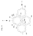
- Fig. 11 a number of (for example, a few thousand) through-holes 100 for allowing the heat transfer tubes 7 to pass through are formed in the central portion (cross-hatched portion in the figure) of the tube support plate 5.
- the through-holes 100 have, for example, a hexagonal shape, and protrusions 100a, 100b, and 100c that protrude towards the center of the through hole 100 are respectively formed on, among the six sides 101, 102, 103, 104, 105, and 106 that form the hexagonal shape, the alternate sides 102, 104, and 106.
- Fig. 11 although only four through-holes 100 are illustrated, in practice, such through-holes 100 are arranged on the tube support plate 5 so as to be aligned vertically and horizontally in a grid pattern.
- a gap is provided between the outer peripheral surface of the heat transfer tubes 7 and the inner peripheral surface of the through-holes 100, and this gap provides a flow path for the secondary cooling water and the steam.
- the through-holes 100 have, in addition to a function of supporting the heat transfer tubes 7, a flowpath function for allowing the secondary cooling water and the steam that flow upwards in the inner cylinder 4 to flow therethrough.
- the lateral load is also propagated to the tube support plate 5.
- the in-plane compressive strength of the tube support plate 5 is not sufficient, there is a risk in that the through-holes 100 will be crushed to contact with the heat transfer tubes 7, and the heat transfer tubes 7 will be deformed (damaged).
- the tube support plate 5 is required to have a certain in-plane compressive strength.
- an evaluation of the in-plane compressive strength of such a tube support plate 5 is performed by forming a small-scale test piece having the same structure as the tube support plate 5, gradually applying a lateral load to this test piece, and reading out the value of the lateral load (hereinafter referred to as "stick load") at which the through hole 100 that is formed in the tube support plate 5 is crushed and makes contact with the heat transfer tubes 7.
- the reason for performing the evaluation using a test piece in this way is that, since the actual dimension of the tube support plate 5 is at least 3 m in diameter and can be as large as about 6 m in diameter, test facilities, test conditions, and so forth are restricted in several ways, and it is difficult to perform the in-plane compressive strength evaluation with the actual plate.
- the in-plane strength will differ, for example, between the case where the load is exerted in the direction of arrow A in the figure and the case where the load is exerted in the direction of arrow B in the figure.
- the tube support plate 5 has anisotropy in that the in-plane strength varies depending on the direction of the load exerted.
- the present invention has been conceived in light of the above-described situation, and an object thereof is to provide an in-plane compressive strength evaluation device that is capable of achieving reduction of cost and improvement of evaluation accuracy, as well as a method therefor.
- a first aspect of the present invention is an in-plane compressive strength evaluation device that is disposed in a steam generator and evaluates an in-plane compressive strength of a tube support plate, in which a number of through-holes, through which heat transfer tubes pass, are formed, the evaluation device including a memory unit in which, when a test piece having substantially a same structure as the tube support plate that is actually used is formed and an in-plane compressive strength evaluation is performed by exerting a load in a state where the heat transfer tubes having a prescribed length are inserted into the through-holes formed in the test piece, respectively, an evaluation result related to the load and a displacement of the test piece is stored as first information; a first analysis unit that obtains, by producing a structural model of the test piece and by performing a simulation of the in-plane compressive strength evaluation under same conditions as the in-plane compressive strength evaluation, second information that is an evaluation result related to the load and the displacement in the structural
- the in-plane compressive strength evaluation is actually performed by forming a test piece having substantially the same structure as the tube support plate that is actually used, and by exerting a load in a state where the heat transfer tubes having the prescribed length are inserted into the through-holes that are formed in this test piece, respectively.
- an evaluation result related to the load and the displacement in the test piece obtained at this time is stored in the memory unit as the first information.
- the structural model of the test piece is produced by the first analysis unit, and the simulation of the in-plane compressive strength evaluation using this structural model of the test piece is performed under the same conditions as the actual conditions, thereby obtaining the second information, which is the evaluation result related to the load and the displacement in the structural model.
- the elemental factor of the structural model is adjusted by the adjustment unit such that the second information approaches the first information.
- the elemental factor that is adjusted at this time is the elemental factor that influences the in-plane compressive strength.
- the structural model is produced at the actual plate level by the second analysis unit by expanding the structural model of the test piece while taking over the elemental factor that is used when the second information approaches the first information most closely, and the in-plane compressive strength evaluation is performed by using this structural model.
- the elemental factor of the structural model of the test piece is adjusted such that the simulation result that is close to the evaluation result of the actual in-plane compressive strength evaluation that is performed using the test piece is obtained, and the simulation of the in-plane compressive strength evaluation is performed by expanding the structural model having the elemental factor that has provided the evaluation result closest to the actual evaluation result into the actual plate.
- test pieces are required to be prepared conventionally in order to consider anisotropy
- only one test piece is required since the test piece is only required for understanding the property of the in-plane compressive strength evaluation of the actual tube support plate. Therefore, it is possible to reduce the cost and effort required for forming the test piece.
- a load can be exerted under various conditions (angles, magnitudes, and so forth) in the simulation, and various evaluations can be performed.
- the elemental factors of the structural model that influence the above-mentioned in-plane compressive strength include, for example, material factors of the structural model and a deformable element factor that defines a deformation of the structural model.
- the material factors include, for example, a material hardening rule etc.
- the deformable element factor is a factor that is used to simply evaluate a three-dimensional model (x, y, and z) as a two-dimensional model (x and y), and it includes, for example, a plane stress factor, a plane strain factor, and so forth.
- the plane stress factor is a factor that defines that the stress in the z-axis direction is zero, in other words, that the structural model deforms freely in the z-axis direction.
- the plane strain factor is a factor that defines that the strain in the z-axis direction is zero, in other words, that the structural model does not deform in the z-axis direction.
- the plane stress factor is applied in a case where the thickness in the z-axis direction is small, and the plane strain factor is applied in a case where the thickness in the z-axis direction is sufficiently large.
- the second analysis unit may perform the in-plane compressive strength evaluation by exerting a sinusoidally or a cosinusoidally distributed load to wedges that are disposed on an outer periphery of the tube support plate at prescribed intervals.
- a second aspect of the present invention is an in-plane compressive strength evaluation method that evaluates an in-plane compressive strength of a tube support plate that is disposed in a steam generator and in which are formed a number of through-holes through which heat transfer tubes pass, the method including a process of forming a test piece having substantially a same structure as the tube support plate that is actually used, performing an in-plane compressive strength evaluation by exerting a load in a state where the heat transfer tubes having a prescribed length are inserted into the through-holes formed in the test piece, respectively, and obtaining an evaluation result related to the load and a displacement in the test piece as first information; a process of obtaining second information that is an evaluation result related to the load and the displacement in a structural model by producing the structural model of the test piece, and by performing a simulation of the in-plane compressive strength evaluation under same conditions as the in-plane compressive strength evaluation; a process of adjusting an elemental factor of the structural model that influences the in-plane compressive strength such that the
- the present invention affords an advantage in that cost reduction can be achieved and evaluation accuracy can be improved.
- An in-plane compressive strength evaluation device is a device that evaluates the in-plane compressive strength of a tube support plate that is disposed in a steam generator, which is used in a nuclear power plant, and that has a number of through-holes through which heat transfer tubes pass through.
- the configuration of the steam generator and the configuration of the tube support plate, which is an evaluation object of the in-plane compressive strength evaluation device according to this embodiment, are shown in Figs. 9 and 10 , and the explanations thereof are described as above. In other words, as shown in Figs.
- a number of through-holes 100 for allowing the heat transfer tubes 7 to pass through are formed in the central portion of the tube support plate 5.
- the tube support plate is disposed horizontally in the steam generator 1 shown in Fig. 9 , and the heat transfer tubes 7 pass through the through-holes 100 perpendicularly.
- the through-holes 100 have, for example, a hexagonal shape.
- a gap is formed between the outer peripheral surface of the heat transfer tubes 7 and the inner peripheral surface of the through-holes 100, and this gap serves as a flow path for the secondary cooling water and the steam.
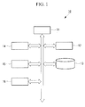
- FIG. 1 shows, in outline, the configuration of an in-plane compressive strength evaluation device according to this embodiment.
- an in-plane compressive strength evaluation device 10 is a computer system (data processing system) that is provided with a CPU (central processing unit) 11, a main storage device 12 such as RAM (random access memory), an auxiliary memory device 13, an input device 14 such as a keyboard or a mouse, a display device 15, and a communication device 16 that communicates with external devices to transfer information.
- a CPU central processing unit
- main storage device 12 such as RAM (random access memory)
- an input device 14 such as a keyboard or a mouse
- a display device a display device
- a communication device 16 that communicates with external devices to transfer information.
- the auxiliary memory device 13 is a computer-readable recording medium, for example, a magnetic disk, a magnetooptical disk, a CD-ROM, a DVD-ROM, a semiconductor memory, and so forth.
- programs for example, an in-plane compressive strength evaluation program
- the CPU 11 reads out the program from the auxiliary memory device 13 to the main storage device 12 and executes the program to realize various processes.
- Fig. 2 is a functional block diagram showing, in an expanded manner, functions of the in-plane compressive strength evaluation device 10.
- the in-plane compressive strength evaluation device 10 is provided with a memory unit 21, a first analysis unit 22, an adjustment unit 23, and a second analysis unit 24.
- a test piece having substantially the same structure as the tube support plate 5 which is actually used in the steam generator is formed, and the heat transfer tubes 7 having prescribed lengths are inserted into the through-holes 100 formed in the test piece, respectively.
- a load is exerted to perform the in-plane compressive strength evaluation.
- An evaluation result related to the load and the displacement in the test piece at this time is stored in the memory unit 21 as first information.
- the in-plane compressive strength evaluation is performed as described below, for example.
- a test piece having substantially the same structure as the tube support plate 5 which is actually used in the steam generator 1 is formed.
- Fig. 3 shows, in outline, a configuration of the test piece.
- the test piece 60 has a square shape and has a configuration in which a number of through-holes 100 are arranged between outer frame portions 40.
- the outer frame portions 40 are provided only on two opposing sides (two sides along the X-direction in Fig. 3 ) of the four sides.
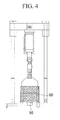
- Fig. 4 is a diagram showing, in outline, the configuration of a loading jig that is used in the in-plane compressive strength evaluation.
- the wedges 50 are disposed at the base of the loading jig, and the test piece 60 is fixed above these wedges 50.
- the test piece 60 is fixed to the loading jig such that the outer frame portions 40 are positioned at the bottom and the top, in other words, such that, in Fig. 3 , the X-direction becomes the horizontal direction and Y-axis extends in the vertical direction.
- the heat transfer tubes 7 having the prescribed length are inserted into the respective through-holes 100 in the test piece 60.
- a load is exerted on the test piece 60 from the upper surface portion thereof, thereby performing the in-plane compressive strength evaluation.
- the in-plane compressive strength evaluation is performed by exerting the load in the prescribed unit and by reading out the vertical displacement of the test piece 60 at this time on two displacement gauges (not shown) disposed on both sides of the test piece 60.
- Fig. 5 shows an example of the evaluation result of the in-plane compressive strength evaluation.
- the horizontal axis indicates the displacement and the vertical axis indicates the load.
- the change in the displacement is small due to elastic deformation; however, when the load exceeds a certain value, the displacement per prescribed amount of load becomes larger as the elastic deformation is replaced by plastic deformation.
- This stick load is the value of the load obtained when a load is exerted on the tube support plate 5 from the outer periphery thereof to cause a gradual deformation of the through-holes 100 that are formed in the plate, and the inner peripheral surface of any one of the through-holes 100 is caused to make contact with the outer peripheral surface of the heat transfer tubes 7 that pass through the through-holes 100.
- This stick load is detected by, for example, an examiner checking the state of all the through-holes 100 every time the load is exerted in the prescribed unit, and by reading out the value of the load being exerted when at least one through hole in which the inner peripheral surface of the through-holes 100 is in contact with the outer peripheral surface of the heat transfer tubes 7 is found.
- first information When the information (hereinafter referred to as "first information") in which the load and the displacement are associated, as shown in Fig. 5 , and the stick load are obtained by performing the in-plane compressive strength evaluation, this first information and stick load are stored in the memory unit of the in-plane compressive strength evaluation device (see Fig. 2 ).
- this first information and stick load are stored in the memory unit of the in-plane compressive strength evaluation device (see Fig. 2 ).
- the configuration of the loading jig used in the in-plane compressive strength evaluation is not limited thereto, and a jig that is capable of performing a test in which a load is exerted on the test piece 60 and a relationship between the load and the displacement is obtained is adequate.
- the first analysis unit 22 by producing a structural model of the test piece 60 used in the above-described actual in-plane compressive strength evaluation and by performing a simulation of the in-plane compressive strength evaluation under the same conditions as the actual in-plane compressive strength evaluation, the first analysis unit 22 obtains second information in which the load and the displacement in the structural model are associated. Specifically, the first analysis unit 22 has a program that produces the structural model of the test piece used in the above-described actual in-plane compressive strength evaluation on the basis of the information input from the input device 14 (see Fig. 1 ) and produces the structural model of the test piece by executing this program.
- the information input from the input device 14 includes, for example, a form factor, a material factor, a boundary condition, a deformable element factor, and so forth.
- the form factor includes, for example, the size of the entire model, the shape and arrangement of the through-holes, and so forth.
- the material factor includes, for example, the Young's modulus, a material hardening rule, and so forth.
- the boundary condition includes, for example, positions of the wedges 50, constraining conditions of the edges of the test piece 60, and so forth.
- the deformable element factor is the deformable element factor that defines the deformation of the structural model and is a factor that is used for simply evaluating a three-dimensional model (x, y, and z) as a two-dimensional model (x and y).
- the deformable element factor includes a plane stress factor, a plane strain factor, and so forth.
- the plane stress factor is a factor that defines the stress in the z-axis direction to be zero, in other words, that the structural model deforms freely in the z-axis direction.
- the plane strain factor is a factor that defines the strain in the z-axis direction to be zero, in other words, that the structural model does not deform in the z-axis direction.
- the plane stress factor is applied in a case where the thickness in the z-axis direction is small, and the plane strain factor is applied in a case where the thickness in the z-axis direction is sufficiently large.
- the above-mentioned information is input by an operator via the input device 14, and the first analysis unit 22 produces the structural model on the basis of the information. Then, the first analysis unit 22 performs the simulation of the in-plane compressive strength evaluation under the same conditions as the actual in-plane compressive strength evaluation by using a numerical analysis method. By doing so, the second information in which the load and the displacement in the structural model are associated is obtained.
- An example of the numerical analysis method includes the finite element method.
- the adjustment unit 23 adjusts the elemental factors that influence the in-plane compressive strength in the structural model such that the second information obtained by the first analysis unit 22 approaches the first information stored in the memory unit 21. Specifically, the adjustment unit 23 first calculates a difference between the first information stored in the memory unit 21 and the second information obtained by the first analysis unit 22 and determines whether or not the maximum value of this difference falls within the pre-set allowable range.
- the material factor and the deformable element factor of the above-mentioned several elemental factors that are used to produce the structural model is changed to modify the structural model.
- the material hardening rule is adjusted as the material factor.
- the first analysis unit 22 then performs the in-plane compressive strength evaluation again using the modified structural model to obtain the second information that differs from the last time. Thereafter, the adjustment unit 23 compares this second information with the first information once again, and determines whether or not the maximum value of the difference falls within the allowable range. The adjustment unit 23 repeatedly updates the combination of the material hardening rule of the material factor and the deformable element factor until the maximum value of the difference falls within the allowable range and obtains the conditions of the factors with which the maximum value of the difference falls within the allowable range.
- the second analysis unit 24 expands the structural model, having the material factors that have been adjusted by the adjustment unit 23 such that the difference between the second information and the first information falls within the allowable range, into the structural form of the tube support plate 5 that is applied to the actual steam generator 1 and performs the in-plane compressive strength evaluation using the expanded structural model.
- the several information related to the actual plate are input through the input device 14.
- the information that is input here includes, for example, the form factor and the boundary conditions.
- the second analysis unit 24 produces the structural model for the actual plate by updating the form factor and the boundary conditions, of the several input information that are used by the first analysis unit 22 for producing the structural model, with the input information that is input at this time.
- the material factor is inherited without any modification when the structural model of the test piece used in the first analysis unit 22 is expanded into the actual plate.
- the structural model of the actual plate can be produced in such a manner that a property that strongly influences the evaluation of the in-plane compressive strength is inherited without any modification. Therefore, the evaluation result of the in-plane compressive strength evaluation of the actual plate that is performed using this structural model is highly reliable.
- the simulation of the in-plane compressive strength evaluation with the structural model of the actual plate is performed by exerting a sinusoidal (or cosinusoidal) load on the respective wedges 50.
- a sinusoidal (or cosinusoidal) load By obtaining the load and the displacement when such a load is exerted, the in-plane compressive strength evaluation is performed.
- the stick load may also be detected in the simulation of the in-plane compressive strength evaluation of the actual plate.
- Step SA1 an actual in-plane compressive strength evaluation using the test piece 60 is performed (Step SA1), and the first information that associates the load and the displacement in the test piece, which are obtained at this time, is stored in the memory unit 21 (Step SA2).
- the structural model of the test piece 60 is produced by the first analysis unit 22, this structural model of the test piece 60 is used to perform the simulation of the in-plane compressive strength evaluation under the same conditions as the actual conditions, and the second information that associates the load and the displacement in the structural model is obtained (Step SA3).
- the adjustment unit 23 adjusts the material factor of the structural model such that the second information approaches the first information and selects the deformable element factor (Step SA4).
- the second analysis unit 24 then expands the structural model that has the material factor that provides the second information that is closest to the first information into the structural form of the tube support plate that is actually applied to the steam generator and performs the in-plane compressive strength evaluation using the expanded structural model (Step SA5).
- the in-plane compressive strength evaluation result obtained with the structural model of the actual plate is stored in the memory unit 21 and is displayed on the display device 15 by being processed into a graph, thereby being presented to the operator (Step SA6).
- the parameters of the structural model are calibrated such that the simulation result is close to the evaluation result of the actually performed in-plane compressive strength evaluation, and the simulation of the in-plane compressive strength evaluation is performed by expanding the structural model having the elemental factors that have provided the evaluation result closest to the actual evaluation result into the actual plate.
- test piece having the same property as the test piece can be produced, the direction in which the load is exerted can be set freely when performing the simulation. Therefore, although two test pieces are required to be prepared conventionally in order to consider the anisotropy, in this embodiment, only one test piece is required, and so, it is possible to reduce the cost and time needed for producing the test piece.
- the adjustment unit 23 may re-input values of the material factor and the deformable element factor through the input device 14 to achieve the adjustment of the material factor and the deformable element factor.
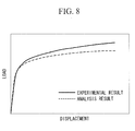
- the material factor is adjusted by displaying a graph, such as that shown in Fig. 8 , in which the first information and the second information are shown in comparison, on the display device 15, and by an operator manually inputting a new value of the material factor through the input device 14 while checking this display screen.
- the adjustment of the elemental factor of the structural model is finished when the maximum value of the difference between the first information and the second information falls within the allowable range, and the structural model of the test piece having the elemental factor at this time is expanded into the actual plate, instead of this, for example, the adjustment of the elemental factor for the structural model may be finished when the maximum value of the difference between the first information and the second information becomes smallest.
- the properties as shown in Fig. 5 are employed as the first information and the second information, and the adjustment of the elemental factor for the structural model is finished when the maximum value of the difference between these properties falls within the allowable range; however, the stick loads may be employed as the first information and the second information.
- the adjustment unit 23 may finish the adjustment of the elemental factor for the structural model when, for example, the difference between the stick load obtained in the actual in-plane compressive strength evaluation and the stick load obtained in the first analysis unit 22 becomes the smallest, or when the difference between the stick loads falls within a preset allowable range (for example, within 5%).
Landscapes
- Engineering & Computer Science (AREA)
- Physics & Mathematics (AREA)
- General Engineering & Computer Science (AREA)
- Mechanical Engineering (AREA)
- Thermal Sciences (AREA)
- Life Sciences & Earth Sciences (AREA)
- General Health & Medical Sciences (AREA)
- Pathology (AREA)
- Analytical Chemistry (AREA)
- Biochemistry (AREA)
- Health & Medical Sciences (AREA)
- General Physics & Mathematics (AREA)
- Immunology (AREA)
- Chemical & Material Sciences (AREA)
- Sustainable Development (AREA)
- Sustainable Energy (AREA)
- High Energy & Nuclear Physics (AREA)
- Plasma & Fusion (AREA)
- Investigating Strength Of Materials By Application Of Mechanical Stress (AREA)
- Monitoring And Testing Of Nuclear Reactors (AREA)
Abstract
Description
- The present invention relates to an in-plane compressive strength evaluation device that analyzes in-plane compressive strength of a tube support plate that is used in a steam generator, and to a method therefor.
- In a nuclear power plant, primary cooling water that has been heated in a nuclear reactor is fed to a steam generator, secondary cooling water is heated in the steam generator with the heat of the primary cooling water to generate secondary steam, and the secondary steam is supplied to a steam turbine to rotate the steam turbine, thereby driving an electric generator.
-
Fig. 9 is a diagram showing, in outline, the configuration of a steam generator that is used in a nuclear power plant. As shown inFig. 9 , a steam generator 1 is provided with a solidouter cylinder 2, atube plate 3 that is formed integrally with theouter cylinder 2, and a number of inverted U-shapedheat transfer tubes 7 both ends of which are inserted in and connected to thetube plate 3. A number ofheat transfer tubes 7 having several bend radii form a heat transfer tube bundle, and the heat transfer tube bundle is surrounded by an inner cylinder 4 and is supported horizontally by a number oftube support plates 5.
A number of through-holes for allowing theheat transfer tube 7 to pass through are formed in thetube support plates 5. Thetube support plates 5 are used for preventing vibration of theheat transfer tubes 7 and for maintaining the mutual spacing between theheat transfer tubes 7. In other words, since a number ofheat transfer tubes 7 pass through thetube support plate 5, the mutual spacing between theheat transfer tubes 7 can be maintained, thus preventing vibration of theheat transfer tubes 7, and, furthermore, even when a lateral load (a load exerted in the horizontal direction) is exerted due to an earthquake etc., this lateral load is borne by thetube support plate 5. - In the steam generator having such a configuration, high-
temperature heating fluid 6 flows into a first water chamber 8, and thisheating fluid 6 flows through theheat transfer tubes 7, provides heat to be cooled, and then, flows out from asecond water chamber 9. Theheating fluid 6 is, for example, a nuclear reactor coolant. In addition,feedwater 31 that has entered by flowing through afeedwater nozzle 30 flows down through the space between the inner cylinder 4 and theouter cylinder 2, turns above thetube plate 3, and flows upwards along theheat transfer tubes 7. While flowing upwards, thefeedwater 31 absorbs heat from theheating fluid 6 through heat exchange, is heated, is boiled, and becomes steam. Thissteam 33 flows out from asteam nozzle 34 and is directed to, for example, a steam turbine. -
Fig. 10 is a plan view of thetube support plate 5 taken from above the steam generator 1. As shown inFig. 10 ,wedges 50 are provided on the outer periphery of thetube support plate 5 at prescribed intervals. When thetube support plate 5 is arranged in the steam generator, thesewedges 50 fill the gap between the inner cylinder 4 and thetube support plate 5.
In addition, a number of (for example, a few thousand) through-holes 100 (seeFig. 11 ) for allowing theheat transfer tubes 7 to pass through are formed in the central portion (cross-hatched portion in the figure) of thetube support plate 5. As shown inFig. 11 , the through-holes 100 have, for example, a hexagonal shape, andprotrusions hole 100 are respectively formed on, among the sixsides alternate sides Fig. 11 , although only four through-holes 100 are illustrated, in practice, such through-holes 100 are arranged on thetube support plate 5 so as to be aligned vertically and horizontally in a grid pattern. In a state where theheat transfer tubes 7 pass through such through-holes 100, respectively, a gap is provided between the outer peripheral surface of theheat transfer tubes 7 and the inner peripheral surface of the through-holes 100, and this gap provides a flow path for the secondary cooling water and the steam. The through-holes 100 have, in addition to a function of supporting theheat transfer tubes 7, a flowpath function for allowing the secondary cooling water and the steam that flow upwards in the inner cylinder 4 to flow therethrough. - When the steam generator 1 experiences a large lateral load due to an earthquake etc., the lateral load is also propagated to the
tube support plate 5. At this time, if the in-plane compressive strength of thetube support plate 5 is not sufficient, there is a risk in that the through-holes 100 will be crushed to contact with theheat transfer tubes 7, and theheat transfer tubes 7 will be deformed (damaged). In order to prevent the occurrence of such a situation, thetube support plate 5 is required to have a certain in-plane compressive strength. - Conventionally, an evaluation of the in-plane compressive strength of such a
tube support plate 5 is performed by forming a small-scale test piece having the same structure as thetube support plate 5, gradually applying a lateral load to this test piece, and reading out the value of the lateral load (hereinafter referred to as "stick load") at which thethrough hole 100 that is formed in thetube support plate 5 is crushed and makes contact with theheat transfer tubes 7. The reason for performing the evaluation using a test piece in this way is that, since the actual dimension of thetube support plate 5 is at least 3 m in diameter and can be as large as about 6 m in diameter, test facilities, test conditions, and so forth are restricted in several ways, and it is difficult to perform the in-plane compressive strength evaluation with the actual plate.
By performing the evaluation of the in-plane compressive strength using a test piece in this way, it is possible to estimate, when a lateral load is exerted on the actual plate, how thetube support plate 5 will deform and the position in the tube support plate where the most severe damage will be caused. -
- {PTL 1} Japanese Unexamined Patent Application, Publication No.
2008-209063 - Since the through-
holes 100 are arranged as shown inFig. 11 , the in-plane strength will differ, for example, between the case where the load is exerted in the direction of arrow A in the figure and the case where the load is exerted in the direction of arrow B in the figure. In other words, thetube support plate 5 has anisotropy in that the in-plane strength varies depending on the direction of the load exerted. Therefore, there is a problem in that, if the in-plane strength evaluation is to be performed by considering the anisotropy, it is necessary to provide at least two test pieces, that is, a test piece for exerting the load in the direction of the arrow A and a test piece for exerting the load in the direction of the arrow B, and enormous cost and effort are required for producing the test pieces. - In addition, errors occur unavoidably upon production of the test pieces, and it is almost impossible to produce the test piece within the set tolerances from the viewpoint of production costs. Therefore, there is a problem in that tolerance evaluation cannot be performed.
- Furthermore, as described above, although the evaluation is performed on test pieces because the evaluation of the actual plate is not possible, there is a problem in that, when evaluation results of the test pieces are applied to the actual plate, and evaluation results of the in-plane compressive strength of the actual plate are to be estimated, there is little information that supports the estimated evaluation results and confidence in the results is low.
- The present invention has been conceived in light of the above-described situation, and an object thereof is to provide an in-plane compressive strength evaluation device that is capable of achieving reduction of cost and improvement of evaluation accuracy, as well as a method therefor.
- In order to solve the above-described problems, the present invention employs the following solutions.
A first aspect of the present invention is an in-plane compressive strength evaluation device that is disposed in a steam generator and evaluates an in-plane compressive strength of a tube support plate, in which a number of through-holes, through which heat transfer tubes pass, are formed, the evaluation device including a memory unit in which, when a test piece having substantially a same structure as the tube support plate that is actually used is formed and an in-plane compressive strength evaluation is performed by exerting a load in a state where the heat transfer tubes having a prescribed length are inserted into the through-holes formed in the test piece, respectively, an evaluation result related to the load and a displacement of the test piece is stored as first information; a first analysis unit that obtains, by producing a structural model of the test piece and by performing a simulation of the in-plane compressive strength evaluation under same conditions as the in-plane compressive strength evaluation, second information that is an evaluation result related to the load and the displacement in the structural model; an adjustment unit that adjusts an elemental factor of the structural model that influences the in-plane compressive strength such that the second information that is obtained by the first analysis unit approaches the first information that is stored in the memory unit; and a second analysis unit that, in a state where the elemental factor that is used when the second information approaches the first information most closely, or when a difference between the second information and the first information falls within an allowable range is maintained, expands the structural model into a structural form of the tube support plate that is actually applied to the steam generator and performs the in-plane compressive strength evaluation using the expanded structural model. - According to the above-described first aspect, the in-plane compressive strength evaluation is actually performed by forming a test piece having substantially the same structure as the tube support plate that is actually used, and by exerting a load in a state where the heat transfer tubes having the prescribed length are inserted into the through-holes that are formed in this test piece, respectively. Thus, an evaluation result related to the load and the displacement in the test piece obtained at this time is stored in the memory unit as the first information.
In addition, the structural model of the test piece is produced by the first analysis unit, and the simulation of the in-plane compressive strength evaluation using this structural model of the test piece is performed under the same conditions as the actual conditions, thereby obtaining the second information, which is the evaluation result related to the load and the displacement in the structural model. When the first information and the second information are obtained, the elemental factor of the structural model is adjusted by the adjustment unit such that the second information approaches the first information. The elemental factor that is adjusted at this time is the elemental factor that influences the in-plane compressive strength. Thereafter, the structural model is produced at the actual plate level by the second analysis unit by expanding the structural model of the test piece while taking over the elemental factor that is used when the second information approaches the first information most closely, and the in-plane compressive strength evaluation is performed by using this structural model. - In this way, the elemental factor of the structural model of the test piece is adjusted such that the simulation result that is close to the evaluation result of the actual in-plane compressive strength evaluation that is performed using the test piece is obtained, and the simulation of the in-plane compressive strength evaluation is performed by expanding the structural model having the elemental factor that has provided the evaluation result closest to the actual evaluation result into the actual plate. By doing so, it is possible to perform the simulation of the actual plate using the structural model, which ensures reproducibility of the experimental result and an increase in the reliability of the evaluation result with the actual plate.
In addition, although at least two test pieces are required to be prepared conventionally in order to consider anisotropy, in the present invention, only one test piece is required since the test piece is only required for understanding the property of the in-plane compressive strength evaluation of the actual tube support plate. Therefore, it is possible to reduce the cost and effort required for forming the test piece. Furthermore, a load can be exerted under various conditions (angles, magnitudes, and so forth) in the simulation, and various evaluations can be performed. - The elemental factors of the structural model that influence the above-mentioned in-plane compressive strength include, for example, material factors of the structural model and a deformable element factor that defines a deformation of the structural model. The material factors include, for example, a material hardening rule etc. In addition, the deformable element factor is a factor that is used to simply evaluate a three-dimensional model (x, y, and z) as a two-dimensional model (x and y), and it includes, for example, a plane stress factor, a plane strain factor, and so forth. The plane stress factor is a factor that defines that the stress in the z-axis direction is zero, in other words, that the structural model deforms freely in the z-axis direction. The plane strain factor is a factor that defines that the strain in the z-axis direction is zero, in other words, that the structural model does not deform in the z-axis direction. For example, the plane stress factor is applied in a case where the thickness in the z-axis direction is small, and the plane strain factor is applied in a case where the thickness in the z-axis direction is sufficiently large.
- In the above-mentioned in-plane compressive strength evaluation device, the second analysis unit may perform the in-plane compressive strength evaluation by exerting a sinusoidally or a cosinusoidally distributed load to wedges that are disposed on an outer periphery of the tube support plate at prescribed intervals.
- In this way, by exerting a sinusoidally or a cosinusoidally distributed load on the outer periphery of the tube support plate, it is possible to perform the simulation of the load that would be exerted on the tube support plate when vibration is propagated to the tube support plate due to an earthquake etc., and to exert a more realistic load on the tube support plate. Therefore, the behavior etc. of the tube support plate and the internal parts thereof in the event of an actual earthquake etc. can be understood.
- A second aspect of the present invention is an in-plane compressive strength evaluation method that evaluates an in-plane compressive strength of a tube support plate that is disposed in a steam generator and in which are formed a number of through-holes through which heat transfer tubes pass, the method including a process of forming a test piece having substantially a same structure as the tube support plate that is actually used, performing an in-plane compressive strength evaluation by exerting a load in a state where the heat transfer tubes having a prescribed length are inserted into the through-holes formed in the test piece, respectively, and obtaining an evaluation result related to the load and a displacement in the test piece as first information; a process of obtaining second information that is an evaluation result related to the load and the displacement in a structural model by producing the structural model of the test piece, and by performing a simulation of the in-plane compressive strength evaluation under same conditions as the in-plane compressive strength evaluation; a process of adjusting an elemental factor of the structural model that influences the in-plane compressive strength such that the second information approaches the first information; and a process of, in a state where the elemental factor that is used when the second information approaches the first information most closely, or when a difference between the second information and the first information falls within an allowable range is maintained, expanding the structural model into a structural form of the tube support plate that is actually applied to the steam generator and performing the in-plane compressive strength evaluation using the expanded structural model.
- The present invention affords an advantage in that cost reduction can be achieved and evaluation accuracy can be improved.
-
- {
FIG. 1} FIG. 1 is a block diagram showing, in outline, the configuration of an in-plane compressive strength evaluation device according to one embodiment of the present invention. - {
FIG. 2} FIG. 2 is a functional block diagram showing, in an expanded manner, functions of an in-plane compressive strength evaluation device according to one embodiment of the present invention. - {
FIG. 3} FIG. 3 is a diagram showing, in outline, the configuration of a test piece. - {
FIG. 4} FIG. 4 is a diagram showing, in outline, the configuration of a loading jig that is used in an in-plane compressive strength evaluation. - {
FIG. 5} FIG. 5 is an example diagram showing evaluation results of an in-plane compressive strength evaluation. - {
FIG. 6} FIG. 6 is an example diagram showing a load exerted on a wedge in a simulation of an in-plane compressive strength evaluation of an actual plate. - {
FIG. 7} FIG. 7 is a flowchart showing operations of an in-plane compressive strength evaluation device according to one embodiment of the present invention. - {
FIG. 8} FIG. 8 is a diagram showing a comparison between evaluation results of an in-plane compressive strength evaluation of an actual test piece and evaluation results of an in-plane compressive strength evaluation by simulation. - {
FIG. 9} FIG. 9 is a diagram showing, in outline, the configuration of a steam generator used in a nuclear power plant. - {
FIG. 10} FIG. 10 is a plan view of a tube support plate taken from above the steam generator. - {
FIG. 11} FIG. 11 is an example diagram showing the shape and arrangement of through-holes. - An embodiment of an in-plane compressive strength evaluation device and a method therefor according to the present invention will be described below with reference to the drawings.
An in-plane compressive strength evaluation device according to one embodiment of the present invention is a device that evaluates the in-plane compressive strength of a tube support plate that is disposed in a steam generator, which is used in a nuclear power plant, and that has a number of through-holes through which heat transfer tubes pass through. The configuration of the steam generator and the configuration of the tube support plate, which is an evaluation object of the in-plane compressive strength evaluation device according to this embodiment, are shown inFigs. 9 and10 , and the explanations thereof are described as above. In other words, as shown inFigs. 10 and11 , a number of through-holes 100 for allowing theheat transfer tubes 7 to pass through are formed in the central portion of thetube support plate 5. The tube support plate is disposed horizontally in the steam generator 1 shown inFig. 9 , and theheat transfer tubes 7 pass through the through-holes 100 perpendicularly. As shown inFig. 11 , the through-holes 100 have, for example, a hexagonal shape. In addition, in a state where theheat transfer tubes 7 pass through the through-holes 100, a gap is formed between the outer peripheral surface of theheat transfer tubes 7 and the inner peripheral surface of the through-holes 100, and this gap serves as a flow path for the secondary cooling water and the steam. -
Fig. 1 shows, in outline, the configuration of an in-plane compressive strength evaluation device according to this embodiment. As shown inFig. 1 , an in-plane compressivestrength evaluation device 10 according to this embodiment is a computer system (data processing system) that is provided with a CPU (central processing unit) 11, amain storage device 12 such as RAM (random access memory), anauxiliary memory device 13, aninput device 14 such as a keyboard or a mouse, adisplay device 15, and acommunication device 16 that communicates with external devices to transfer information. - The
auxiliary memory device 13 is a computer-readable recording medium, for example, a magnetic disk, a magnetooptical disk, a CD-ROM, a DVD-ROM, a semiconductor memory, and so forth. Several programs (for example, an in-plane compressive strength evaluation program) are stored in thisauxiliary memory device 13, and theCPU 11 reads out the program from theauxiliary memory device 13 to themain storage device 12 and executes the program to realize various processes. -
Fig. 2 is a functional block diagram showing, in an expanded manner, functions of the in-plane compressivestrength evaluation device 10. As shown inFig. 2 , the in-plane compressivestrength evaluation device 10 is provided with amemory unit 21, afirst analysis unit 22, anadjustment unit 23, and asecond analysis unit 24. - A test piece having substantially the same structure as the
tube support plate 5 which is actually used in the steam generator is formed, and theheat transfer tubes 7 having prescribed lengths are inserted into the through-holes 100 formed in the test piece, respectively. In this state, a load is exerted to perform the in-plane compressive strength evaluation. An evaluation result related to the load and the displacement in the test piece at this time is stored in thememory unit 21 as first information. - The in-plane compressive strength evaluation is performed as described below, for example.
In the in-plane compressive strength evaluation performed prior to the simulation, a test piece having substantially the same structure as thetube support plate 5 which is actually used in the steam generator 1 is formed.Fig. 3 shows, in outline, a configuration of the test piece. As shown inFig. 3 , thetest piece 60 has a square shape and has a configuration in which a number of through-holes 100 are arranged betweenouter frame portions 40. Theouter frame portions 40 are provided only on two opposing sides (two sides along the X-direction inFig. 3 ) of the four sides. -
Fig. 4 is a diagram showing, in outline, the configuration of a loading jig that is used in the in-plane compressive strength evaluation. Thewedges 50 are disposed at the base of the loading jig, and thetest piece 60 is fixed above thesewedges 50. At this time, thetest piece 60 is fixed to the loading jig such that theouter frame portions 40 are positioned at the bottom and the top, in other words, such that, inFig. 3 , the X-direction becomes the horizontal direction and Y-axis extends in the vertical direction. In this state, theheat transfer tubes 7 having the prescribed length are inserted into the respective through-holes 100 in thetest piece 60. In a state where theheat transfer tubes 7 are inserted into the respective through-holes 100 in thetest piece 60, a load is exerted on thetest piece 60 from the upper surface portion thereof, thereby performing the in-plane compressive strength evaluation. The in-plane compressive strength evaluation is performed by exerting the load in the prescribed unit and by reading out the vertical displacement of thetest piece 60 at this time on two displacement gauges (not shown) disposed on both sides of thetest piece 60.Fig. 5 shows an example of the evaluation result of the in-plane compressive strength evaluation. InFig. 5 , the horizontal axis indicates the displacement and the vertical axis indicates the load. In the region where the load is small, the change in the displacement is small due to elastic deformation; however, when the load exceeds a certain value, the displacement per prescribed amount of load becomes larger as the elastic deformation is replaced by plastic deformation. - In addition, in the in-plane compressive strength evaluation, a detection of the stick load is performed as well as acquisition of the graph shown in
Fig. 5 . This stick load is the value of the load obtained when a load is exerted on thetube support plate 5 from the outer periphery thereof to cause a gradual deformation of the through-holes 100 that are formed in the plate, and the inner peripheral surface of any one of the through-holes 100 is caused to make contact with the outer peripheral surface of theheat transfer tubes 7 that pass through the through-holes 100. This stick load is detected by, for example, an examiner checking the state of all the through-holes 100 every time the load is exerted in the prescribed unit, and by reading out the value of the load being exerted when at least one through hole in which the inner peripheral surface of the through-holes 100 is in contact with the outer peripheral surface of theheat transfer tubes 7 is found. - When the information (hereinafter referred to as "first information") in which the load and the displacement are associated, as shown in
Fig. 5 , and the stick load are obtained by performing the in-plane compressive strength evaluation, this first information and stick load are stored in the memory unit of the in-plane compressive strength evaluation device (seeFig. 2 ).
In this embodiment, although a configuration in which the loading jig having a configuration shown inFig. 4 is used, the load is exerted on thetest piece 60 from the upper surface portion thereof, and this load is received by thewedges 50 disposed on the base is employed, the configuration of the loading jig used in the in-plane compressive strength evaluation is not limited thereto, and a jig that is capable of performing a test in which a load is exerted on thetest piece 60 and a relationship between the load and the displacement is obtained is adequate. - Referring back to
Fig. 2 , by producing a structural model of thetest piece 60 used in the above-described actual in-plane compressive strength evaluation and by performing a simulation of the in-plane compressive strength evaluation under the same conditions as the actual in-plane compressive strength evaluation, thefirst analysis unit 22 obtains second information in which the load and the displacement in the structural model are associated.
Specifically, thefirst analysis unit 22 has a program that produces the structural model of the test piece used in the above-described actual in-plane compressive strength evaluation on the basis of the information input from the input device 14 (seeFig. 1 ) and produces the structural model of the test piece by executing this program. - The information input from the
input device 14 includes, for example, a form factor, a material factor, a boundary condition, a deformable element factor, and so forth. The form factor includes, for example, the size of the entire model, the shape and arrangement of the through-holes, and so forth. The material factor includes, for example, the Young's modulus, a material hardening rule, and so forth. The boundary condition includes, for example, positions of thewedges 50, constraining conditions of the edges of thetest piece 60, and so forth. In addition, the deformable element factor is the deformable element factor that defines the deformation of the structural model and is a factor that is used for simply evaluating a three-dimensional model (x, y, and z) as a two-dimensional model (x and y). Specifically, the deformable element factor includes a plane stress factor, a plane strain factor, and so forth. The plane stress factor is a factor that defines the stress in the z-axis direction to be zero, in other words, that the structural model deforms freely in the z-axis direction. The plane strain factor is a factor that defines the strain in the z-axis direction to be zero, in other words, that the structural model does not deform in the z-axis direction. For example, the plane stress factor is applied in a case where the thickness in the z-axis direction is small, and the plane strain factor is applied in a case where the thickness in the z-axis direction is sufficiently large. - The above-mentioned information is input by an operator via the
input device 14, and thefirst analysis unit 22 produces the structural model on the basis of the information. Then, thefirst analysis unit 22 performs the simulation of the in-plane compressive strength evaluation under the same conditions as the actual in-plane compressive strength evaluation by using a numerical analysis method. By doing so, the second information in which the load and the displacement in the structural model are associated is obtained. An example of the numerical analysis method includes the finite element method. - The
adjustment unit 23 adjusts the elemental factors that influence the in-plane compressive strength in the structural model such that the second information obtained by thefirst analysis unit 22 approaches the first information stored in thememory unit 21.
Specifically, theadjustment unit 23 first calculates a difference between the first information stored in thememory unit 21 and the second information obtained by thefirst analysis unit 22 and determines whether or not the maximum value of this difference falls within the pre-set allowable range. - As a result of this, if the maximum value of the difference does not fall within the allowable range, at least one of the material factor and the deformable element factor of the above-mentioned several elemental factors that are used to produce the structural model is changed to modify the structural model. Specifically, in this embodiment, the material hardening rule is adjusted as the material factor. In addition, any factor of a plurality of deformable element factors, such as the pre-set plane stress factor, plane strain factor, and so forth, is selected as the deformable element factor, for example.
- The
first analysis unit 22 then performs the in-plane compressive strength evaluation again using the modified structural model to obtain the second information that differs from the last time. Thereafter, theadjustment unit 23 compares this second information with the first information once again, and determines whether or not the maximum value of the difference falls within the allowable range. Theadjustment unit 23 repeatedly updates the combination of the material hardening rule of the material factor and the deformable element factor until the maximum value of the difference falls within the allowable range and obtains the conditions of the factors with which the maximum value of the difference falls within the allowable range. - The
second analysis unit 24 expands the structural model, having the material factors that have been adjusted by theadjustment unit 23 such that the difference between the second information and the first information falls within the allowable range, into the structural form of thetube support plate 5 that is applied to the actual steam generator 1 and performs the in-plane compressive strength evaluation using the expanded structural model. Specifically, upon the expansion into the actual plate, the several information related to the actual plate are input through theinput device 14. The information that is input here includes, for example, the form factor and the boundary conditions. Thesecond analysis unit 24 produces the structural model for the actual plate by updating the form factor and the boundary conditions, of the several input information that are used by thefirst analysis unit 22 for producing the structural model, with the input information that is input at this time. - The material factor is inherited without any modification when the structural model of the test piece used in the
first analysis unit 22 is expanded into the actual plate. In this way, by producing the structural model of the actual plate by employing the values of the material factor for the test piece without any modification, the structural model of the actual plate can be produced in such a manner that a property that strongly influences the evaluation of the in-plane compressive strength is inherited without any modification. Therefore, the evaluation result of the in-plane compressive strength evaluation of the actual plate that is performed using this structural model is highly reliable. - As shown in
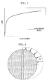
Fig. 6 , the simulation of the in-plane compressive strength evaluation with the structural model of the actual plate is performed by exerting a sinusoidal (or cosinusoidal) load on therespective wedges 50. By obtaining the load and the displacement when such a load is exerted, the in-plane compressive strength evaluation is performed. In addition, the stick load may also be detected in the simulation of the in-plane compressive strength evaluation of the actual plate. - Next, the operation of the in-plane compressive
strength evaluation device 10 having the above-mentioned configuration will be briefly described with reference toFig. 7 . Prior to the in-plane compressive strength evaluation with the in-plane compressivestrength evaluation device 10, an actual in-plane compressive strength evaluation using thetest piece 60 is performed (Step SA1), and the first information that associates the load and the displacement in the test piece, which are obtained at this time, is stored in the memory unit 21 (Step SA2).
In the in-plane compressive strength evaluation with the in-plane compressivestrength evaluation device 10, the structural model of thetest piece 60 is produced by thefirst analysis unit 22, this structural model of thetest piece 60 is used to perform the simulation of the in-plane compressive strength evaluation under the same conditions as the actual conditions, and the second information that associates the load and the displacement in the structural model is obtained (Step SA3). - After obtaining the first information and the second information, the
adjustment unit 23 adjusts the material factor of the structural model such that the second information approaches the first information and selects the deformable element factor (Step SA4). Thesecond analysis unit 24 then expands the structural model that has the material factor that provides the second information that is closest to the first information into the structural form of the tube support plate that is actually applied to the steam generator and performs the in-plane compressive strength evaluation using the expanded structural model (Step SA5). The in-plane compressive strength evaluation result obtained with the structural model of the actual plate is stored in thememory unit 21 and is displayed on thedisplay device 15 by being processed into a graph, thereby being presented to the operator (Step SA6). - As described above, according to the in-plane compressive strength evaluation device and the method therefor of this embodiment, the parameters of the structural model are calibrated such that the simulation result is close to the evaluation result of the actually performed in-plane compressive strength evaluation, and the simulation of the in-plane compressive strength evaluation is performed by expanding the structural model having the elemental factors that have provided the evaluation result closest to the actual evaluation result into the actual plate. By doing so, it is possible to perform the simulation of the actual plate using the structural model, which ensures reproducibility of the experimental result and an increase in the reliability of the evaluation result with the actual plate.
- Furthermore, if a structural model having the same property as the test piece can be produced, the direction in which the load is exerted can be set freely when performing the simulation. Therefore, although two test pieces are required to be prepared conventionally in order to consider the anisotropy, in this embodiment, only one test piece is required, and so, it is possible to reduce the cost and time needed for producing the test piece.
- In this embodiment, although the descriptions assumed that the
adjustment unit 23 automatically updates the material hardening rule of the material factor and the deformable element factor to obtain the suitable values, an operator, for example, may re-input values of the material factor and the deformable element factor through theinput device 14 to achieve the adjustment of the material factor and the deformable element factor. In this case, for example, it is possible to consider an aspect in which the material factor is adjusted by displaying a graph, such as that shown inFig. 8 , in which the first information and the second information are shown in comparison, on thedisplay device 15, and by an operator manually inputting a new value of the material factor through theinput device 14 while checking this display screen. - In addition, in this embodiment, although the descriptions assumed that the adjustment of the elemental factor of the structural model is finished when the maximum value of the difference between the first information and the second information falls within the allowable range, and the structural model of the test piece having the elemental factor at this time is expanded into the actual plate, instead of this, for example, the adjustment of the elemental factor for the structural model may be finished when the maximum value of the difference between the first information and the second information becomes smallest.
- In addition, in this embodiment, the properties as shown in
Fig. 5 , in which the load and the displacement are associated, are employed as the first information and the second information, and the adjustment of the elemental factor for the structural model is finished when the maximum value of the difference between these properties falls within the allowable range; however, the stick loads may be employed as the first information and the second information. In this case, theadjustment unit 23 may finish the adjustment of the elemental factor for the structural model when, for example, the difference between the stick load obtained in the actual in-plane compressive strength evaluation and the stick load obtained in thefirst analysis unit 22 becomes the smallest, or when the difference between the stick loads falls within a preset allowable range (for example, within 5%). -
- 1
- steam generator
- 5
- tube support plate
- 7
- heat transfer tube
- 10
- in-plane compressive strength evaluation device
- 11
- CPU
- 12
- main storage device
- 13
- auxiliary memory device
- 14
- input device
- 15
- display device
- 16
- communication device
- 21
- memory unit
- 22
- first analysis unit
- 23
- adjustment unit
- 24
- second analysis unit
- 40
- outer frame portion
- 50
- wedge
- 60
- test piece
- 100
- through-hole
Claims (3)
- An in-plane compressive strength evaluation device that is disposed in a steam generator and evaluates an in-plane compressive strength of a tube support plate, in which are formed a number of through-holes through which heat transfer tubes pass, the in-plane compressive strength evaluation device comprising:a memory unit in which, when a test piece having substantially a same structure as the tube support plate that is actually used is formed and an in-plane compressive strength evaluation is performed by exerting a load in a state where the heat transfer tubes having a prescribed length are inserted into the through-holes formed in the test piece, respectively, an evaluation result related to the load and a displacement of the test piece is stored as first information;a first analysis unit that obtains, by producing a structural model of the test piece and by performing a simulation of the in-plane compressive strength evaluation under same conditions as the in-plane compressive strength evaluation, second information that is an evaluation result related to the load and the displacement in the structural model;an adjustment unit that adjusts an elemental factor of the structural model that influences the in-plane compressive strength such that the second information that is obtained by the first analysis unit approaches the first information that is stored in the memory unit; anda second analysis unit that, in a state where the elemental factor that is used when the second information approaches the first information most closely, or when a difference between the second information and the first information falls within an allowable range is maintained, expands the structural model into a structural form of the tube support plate that is actually applied to the steam generator and performs the in-plane compressive strength evaluation using the expanded structural model.
- An in-plane compressive strength evaluation device according to Claim 1, wherein the second analysis unit performs the in-plane compressive strength evaluation by exerting a sinusoidally or a cosinusoidally distributed load to wedges that are disposed on an outer periphery of the tube support plate at prescribed intervals.
- An in-plane compressive strength evaluation method that evaluates an in-plane compressive strength of a tube support plate that is disposed in a steam generator and in which are formed a number of through-holes through which heat transfer tubes pass, the in-plane compressive strength evaluation method comprising:a process of forming a test piece having substantially a same structure as the tube support plate that is actually used, performing an in-plane compressive strength evaluation by exerting a load in a state where the heat transfer tubes having a prescribed length are inserted into the through-holes formed in the test piece, respectively, and obtaining an evaluation result related to the load and a displacement in the test piece as first information;a process of obtaining second information that is an evaluation result related to the load and the displacement in a structural model by producing the structural model of the test piece and by performing a simulation of the in-plane compressive strength evaluation under same conditions as the in-plane compressive strength evaluation;a process of adjusting an elemental factor of the structural model that influences the in-plane compressive strength such that the second information approaches the first information; anda process of, in a state where the elemental factor that is used when the second information approaches the first information most closely, or when a difference between the second information and the first information falls within an allowable range is maintained, expanding the structural model into a structural form of the tube support plate that is actually applied to the steam generator and performing the in-plane compressive strength evaluation using the expanded structural model.
Applications Claiming Priority (2)
| Application Number | Priority Date | Filing Date | Title |
|---|---|---|---|
| JP2009139463A JP5804668B2 (en) | 2009-06-10 | 2009-06-10 | In-plane compressive strength evaluation apparatus and method |
| PCT/JP2009/071149 WO2010143324A1 (en) | 2009-06-10 | 2009-12-18 | Inplane compressive strength evaluation device and method |
Publications (3)
| Publication Number | Publication Date |
|---|---|
| EP2442090A1 true EP2442090A1 (en) | 2012-04-18 |
| EP2442090A4 EP2442090A4 (en) | 2015-04-01 |
| EP2442090B1 EP2442090B1 (en) | 2016-04-20 |
Family
ID=43308588
Family Applications (1)
| Application Number | Title | Priority Date | Filing Date |
|---|---|---|---|
| EP09845846.6A Active EP2442090B1 (en) | 2009-06-10 | 2009-12-18 | Inplane compressive strength evaluation device and method |
Country Status (5)
| Country | Link |
|---|---|
| US (1) | US8301402B2 (en) |
| EP (1) | EP2442090B1 (en) |
| JP (1) | JP5804668B2 (en) |
| KR (1) | KR101284999B1 (en) |
| WO (1) | WO2010143324A1 (en) |
Families Citing this family (11)
| Publication number | Priority date | Publication date | Assignee | Title |
|---|---|---|---|---|
| CN104394884A (en) * | 2012-03-21 | 2015-03-04 | 爱瑞泰克药物公司 | Medicament for the treatment of acute myeloid leukemia (AML) |
| JP6317602B2 (en) * | 2014-03-11 | 2018-04-25 | アサヒビール株式会社 | Buckling load estimation method and program |
| JP6497588B2 (en) * | 2015-08-31 | 2019-04-10 | 三菱重工業株式会社 | Deformation stress characteristic acquisition method and seismic evaluation method of heat exchanger |
| JP6803244B2 (en) * | 2017-01-20 | 2020-12-23 | 三菱重工業株式会社 | Heat exchanger analysis method |
| CN109974956B (en) * | 2017-12-28 | 2024-03-22 | 明门(中国)幼童用品有限公司 | Column support piece strength testing device |
| KR101954824B1 (en) * | 2018-07-31 | 2019-03-06 | 목포대학교산학협력단 | Apparatus for ultimate strength test of scaffold joint bracket and method thereof |
| CN111967101B (en) * | 2020-07-28 | 2025-01-24 | 同济大学 | A method for designing a deep-sea pressure simulation device by mechanical pressurization |
| CN113158516B (en) * | 2021-03-31 | 2023-02-28 | 中国飞机强度研究所 | Method and device for constructing finite element model of clamp of cylindrical structural strength test piece |
| CN114582219B (en) * | 2022-02-23 | 2023-08-11 | 山东高速工程建设集团有限公司 | Foundation pit adjacent building construction simulation device |
| CN114735237B (en) * | 2022-06-14 | 2022-08-30 | 中国飞机强度研究所 | In-plane out-of-plane static force applying structure and method for impact test of airplane structural component |
| CN120741211B (en) * | 2025-08-22 | 2025-11-14 | 北京理工大学 | Pipeline compressive property detection device |
Family Cites Families (20)
| Publication number | Priority date | Publication date | Assignee | Title |
|---|---|---|---|---|
| JPH03255892A (en) | 1990-03-07 | 1991-11-14 | Hitachi Ltd | Heat exchanger tube support structure |
| US5685693A (en) * | 1995-03-31 | 1997-11-11 | General Electric Co. | Removable inner turbine shell with bucket tip clearance control |
| JP3039332B2 (en) * | 1995-08-09 | 2000-05-08 | 鹿島建設株式会社 | Testing method of variable damping device for damping structure |
| JP2772275B2 (en) | 1996-01-10 | 1998-07-02 | 三菱重工業株式会社 | Working device in steam generator |
| US5832421A (en) * | 1996-12-13 | 1998-11-03 | Siemens Corporate Research, Inc. | Method for blade temperature estimation in a steam turbine |
| EP1055180B1 (en) * | 1998-12-03 | 2011-07-20 | Siemens Aktiengesellschaft | Method and device for designing a technical system |
| US6775645B2 (en) * | 2001-11-14 | 2004-08-10 | Electric Power Research Institute, Inc. | Application of symbol sequence analysis and temporal irreversibility to monitoring and controlling boiler flames |
| US7353140B2 (en) * | 2001-11-14 | 2008-04-01 | Electric Power Research Institute, Inc. | Methods for monitoring and controlling boiler flames |
| US7231323B2 (en) * | 2001-12-21 | 2007-06-12 | International Paper Company | Environmental monitoring and reporting system for EPA cluster rule 010094 |
| FR2846139B1 (en) * | 2002-10-21 | 2005-02-18 | Framatome Anp | METHOD FOR DETERMINING A LIMIT VALUE OF AN OPERATING PARAMETER OF A NUCLEAR REACTOR, PROGRAM AND SUPPORT THEREFOR |
| US6853945B2 (en) * | 2003-03-27 | 2005-02-08 | General Electric Company | Method of on-line monitoring of radial clearances in steam turbines |
| JP4457663B2 (en) | 2003-12-25 | 2010-04-28 | 日産自動車株式会社 | Stiffness analysis method and program thereof |
| DE102005004233A1 (en) * | 2005-01-28 | 2006-08-17 | Abb Research Ltd. | System and method for resource planning, process monitoring, simulation and optimization of a combined power generation and desalination plant |
| JP2006258588A (en) * | 2005-03-16 | 2006-09-28 | Olympus Corp | Aquiring method of physical properties of impact analyzing material |
| JP4339808B2 (en) * | 2005-03-31 | 2009-10-07 | 横浜ゴム株式会社 | Structure design method |
| US8065022B2 (en) * | 2005-09-06 | 2011-11-22 | General Electric Company | Methods and systems for neural network modeling of turbine components |
| JP4788564B2 (en) | 2006-10-19 | 2011-10-05 | 株式会社豊田中央研究所 | Structure stiffness analysis system and program |
| JP5072388B2 (en) | 2007-02-27 | 2012-11-14 | 三菱重工業株式会社 | Steam generator tube support plate |
| US8651156B2 (en) * | 2009-06-24 | 2014-02-18 | Compagnie Generale Des Etablissements Michelin | Honeycomb structures for high shear flexure |
| US8396572B2 (en) * | 2009-09-11 | 2013-03-12 | Siemens Corporation | System and method for energy plant optimization using mixed integer-linear programming |
-
2009
- 2009-06-10 JP JP2009139463A patent/JP5804668B2/en active Active
- 2009-12-18 EP EP09845846.6A patent/EP2442090B1/en active Active
- 2009-12-18 US US13/146,677 patent/US8301402B2/en active Active
- 2009-12-18 KR KR1020117017631A patent/KR101284999B1/en active Active
- 2009-12-18 WO PCT/JP2009/071149 patent/WO2010143324A1/en not_active Ceased
Non-Patent Citations (2)
| Title |
|---|
| No further relevant documents disclosed * |
| See also references of WO2010143324A1 * |
Also Published As
| Publication number | Publication date |
|---|---|
| US8301402B2 (en) | 2012-10-30 |
| KR101284999B1 (en) | 2013-07-10 |
| JP5804668B2 (en) | 2015-11-04 |
| EP2442090A4 (en) | 2015-04-01 |
| US20110277554A1 (en) | 2011-11-17 |
| JP2010286317A (en) | 2010-12-24 |
| EP2442090B1 (en) | 2016-04-20 |
| WO2010143324A1 (en) | 2010-12-16 |
| KR20110102479A (en) | 2011-09-16 |
Similar Documents
| Publication | Publication Date | Title |
|---|---|---|
| EP2442090B1 (en) | Inplane compressive strength evaluation device and method | |
| JP6086752B2 (en) | Seismic evaluation method for steam generator | |
| Lee et al. | Creep-fatigue damage evaluation of sodium to air heat exchanger in sodium test loop facility | |
| Kim | Structural analysis of CSB and LSS for APR1400 RVI CVAP | |
| KR102033927B1 (en) | Seismic Analysis Method considering refrigerant flow according to operating conditions of Nuclear power plant | |
| EP3550457B1 (en) | Method for analyzing heat exchanger | |
| de la Torre et al. | Design analysis of a printed circuit heat exchanger for HTGR using a 3D finite elements model | |
| CN121580549B (en) | Method, device, equipment and medium for elastoplastic analysis and strength verification under multiple working conditions | |
| Janulionis et al. | Numerical simulation of low-cycle fatigue test of welded 9Cr-1Mo steel at 550° C | |
| JP2016509234A (en) | Method and apparatus for measuring tube pressure | |
| Eswaran et al. | Investigation of flow-induced vibration in core sub-assemblies of sodium-cooled fast reactors | |
| CN107369482A (en) | Single fast pile component hot-bend test restraint device and thermal deformation contact measurement method | |
| JP2014063262A (en) | Stress distribution estimation method, and analysis method and analysis system using the same | |
| Junior et al. | Thermal Stress Analysis of Compact Heat Exchanger Produced by Additive Manufacturing | |
| King et al. | Flow induced vibration and fretting wear in PWR fuel | |
| JP6497588B2 (en) | Deformation stress characteristic acquisition method and seismic evaluation method of heat exchanger | |
| WO2025145660A1 (en) | Operation and maintenance assisting method and system for heat transfer tube bundle of steam generator, and medium and device | |
| Lan et al. | A study on the seismic test of a planar model of the gas-cooled microreactor | |
| Kim et al. | Hydraulic and Structural Analysis Methodology of RVI CVAP in Shin-Kori 4 | |
| CN107389434B (en) | 60° Sector Fast Reactor Component Constraint Device and Thermal Deformation Contact Measurement Method | |
| Ma et al. | Shakedown and creep rupture analysis of printed circuit heat exchangers based on the linear matching method framework | |
| Schettino et al. | Efficacy of beam-type finite elements in the evaluation of lateral stiffness of 16× 16 fuel assemblies by strengthening mechanisms | |
| Broc et al. | Core mechanical dynamics experiment in the Phenix reactor | |
| Fontaine et al. | Recent analyses of PHENIX End of Life Tests and perspectives | |
| Muhammad et al. | Analysis of a Support Base Stand using Finite Element Analysis |
Legal Events
| Date | Code | Title | Description |
|---|---|---|---|
| PUAI | Public reference made under article 153(3) epc to a published international application that has entered the european phase |
Free format text: ORIGINAL CODE: 0009012 |
|
| 17P | Request for examination filed |
Effective date: 20110728 |
|
| AK | Designated contracting states |
Kind code of ref document: A1 Designated state(s): AT BE BG CH CY CZ DE DK EE ES FI FR GB GR HR HU IE IS IT LI LT LU LV MC MK MT NL NO PL PT RO SE SI SK SM TR |
|
| DAX | Request for extension of the european patent (deleted) | ||
| RA4 | Supplementary search report drawn up and despatched (corrected) |
Effective date: 20150304 |
|
| RIC1 | Information provided on ipc code assigned before grant |
Ipc: G21D 1/00 20060101ALI20150226BHEP Ipc: F22B 37/20 20060101ALI20150226BHEP Ipc: G21C 17/00 20060101ALI20150226BHEP Ipc: G01N 3/08 20060101AFI20150226BHEP Ipc: F22B 1/16 20060101ALI20150226BHEP |
|
| GRAP | Despatch of communication of intention to grant a patent |
Free format text: ORIGINAL CODE: EPIDOSNIGR1 |
|
| INTG | Intention to grant announced |
Effective date: 20151106 |
|
| GRAS | Grant fee paid |
Free format text: ORIGINAL CODE: EPIDOSNIGR3 |
|
| GRAA | (expected) grant |
Free format text: ORIGINAL CODE: 0009210 |
|
| AK | Designated contracting states |
Kind code of ref document: B1 Designated state(s): AT BE BG CH CY CZ DE DK EE ES FI FR GB GR HR HU IE IS IT LI LT LU LV MC MK MT NL NO PL PT RO SE SI SK SM TR |
|
| REG | Reference to a national code |
Ref country code: GB Ref legal event code: FG4D |
|
| REG | Reference to a national code |
Ref country code: CH Ref legal event code: EP |
|
| REG | Reference to a national code |
Ref country code: AT Ref legal event code: REF Ref document number: 792974 Country of ref document: AT Kind code of ref document: T Effective date: 20160515 |
|
| REG | Reference to a national code |
Ref country code: IE Ref legal event code: FG4D |
|
| REG | Reference to a national code |
Ref country code: DE Ref legal event code: R096 Ref document number: 602009038124 Country of ref document: DE |
|
| REG | Reference to a national code |
Ref country code: LT Ref legal event code: MG4D |
|
| REG | Reference to a national code |
Ref country code: AT Ref legal event code: MK05 Ref document number: 792974 Country of ref document: AT Kind code of ref document: T Effective date: 20160420 |
|
| REG | Reference to a national code |
Ref country code: NL Ref legal event code: MP Effective date: 20160420 |
|
| PG25 | Lapsed in a contracting state [announced via postgrant information from national office to epo] |
Ref country code: FI Free format text: LAPSE BECAUSE OF FAILURE TO SUBMIT A TRANSLATION OF THE DESCRIPTION OR TO PAY THE FEE WITHIN THE PRESCRIBED TIME-LIMIT Effective date: 20160420 Ref country code: NO Free format text: LAPSE BECAUSE OF FAILURE TO SUBMIT A TRANSLATION OF THE DESCRIPTION OR TO PAY THE FEE WITHIN THE PRESCRIBED TIME-LIMIT Effective date: 20160720 Ref country code: PL Free format text: LAPSE BECAUSE OF FAILURE TO SUBMIT A TRANSLATION OF THE DESCRIPTION OR TO PAY THE FEE WITHIN THE PRESCRIBED TIME-LIMIT Effective date: 20160420 Ref country code: NL Free format text: LAPSE BECAUSE OF FAILURE TO SUBMIT A TRANSLATION OF THE DESCRIPTION OR TO PAY THE FEE WITHIN THE PRESCRIBED TIME-LIMIT Effective date: 20160420 Ref country code: LT Free format text: LAPSE BECAUSE OF FAILURE TO SUBMIT A TRANSLATION OF THE DESCRIPTION OR TO PAY THE FEE WITHIN THE PRESCRIBED TIME-LIMIT Effective date: 20160420 |
|
| REG | Reference to a national code |
Ref country code: FR Ref legal event code: PLFP Year of fee payment: 8 |
|
| PG25 | Lapsed in a contracting state [announced via postgrant information from national office to epo] |
Ref country code: SE Free format text: LAPSE BECAUSE OF FAILURE TO SUBMIT A TRANSLATION OF THE DESCRIPTION OR TO PAY THE FEE WITHIN THE PRESCRIBED TIME-LIMIT Effective date: 20160420 Ref country code: LV Free format text: LAPSE BECAUSE OF FAILURE TO SUBMIT A TRANSLATION OF THE DESCRIPTION OR TO PAY THE FEE WITHIN THE PRESCRIBED TIME-LIMIT Effective date: 20160420 Ref country code: GR Free format text: LAPSE BECAUSE OF FAILURE TO SUBMIT A TRANSLATION OF THE DESCRIPTION OR TO PAY THE FEE WITHIN THE PRESCRIBED TIME-LIMIT Effective date: 20160721 Ref country code: AT Free format text: LAPSE BECAUSE OF FAILURE TO SUBMIT A TRANSLATION OF THE DESCRIPTION OR TO PAY THE FEE WITHIN THE PRESCRIBED TIME-LIMIT Effective date: 20160420 Ref country code: HR Free format text: LAPSE BECAUSE OF FAILURE TO SUBMIT A TRANSLATION OF THE DESCRIPTION OR TO PAY THE FEE WITHIN THE PRESCRIBED TIME-LIMIT Effective date: 20160420 Ref country code: PT Free format text: LAPSE BECAUSE OF FAILURE TO SUBMIT A TRANSLATION OF THE DESCRIPTION OR TO PAY THE FEE WITHIN THE PRESCRIBED TIME-LIMIT Effective date: 20160822 Ref country code: ES Free format text: LAPSE BECAUSE OF FAILURE TO SUBMIT A TRANSLATION OF THE DESCRIPTION OR TO PAY THE FEE WITHIN THE PRESCRIBED TIME-LIMIT Effective date: 20160420 |
|
| PG25 | Lapsed in a contracting state [announced via postgrant information from national office to epo] |
Ref country code: IT Free format text: LAPSE BECAUSE OF FAILURE TO SUBMIT A TRANSLATION OF THE DESCRIPTION OR TO PAY THE FEE WITHIN THE PRESCRIBED TIME-LIMIT Effective date: 20160420 Ref country code: BE Free format text: LAPSE BECAUSE OF FAILURE TO SUBMIT A TRANSLATION OF THE DESCRIPTION OR TO PAY THE FEE WITHIN THE PRESCRIBED TIME-LIMIT Effective date: 20160420 |
|
| REG | Reference to a national code |
Ref country code: DE Ref legal event code: R097 Ref document number: 602009038124 Country of ref document: DE |
|
| PG25 | Lapsed in a contracting state [announced via postgrant information from national office to epo] |
Ref country code: EE Free format text: LAPSE BECAUSE OF FAILURE TO SUBMIT A TRANSLATION OF THE DESCRIPTION OR TO PAY THE FEE WITHIN THE PRESCRIBED TIME-LIMIT Effective date: 20160420 Ref country code: RO Free format text: LAPSE BECAUSE OF FAILURE TO SUBMIT A TRANSLATION OF THE DESCRIPTION OR TO PAY THE FEE WITHIN THE PRESCRIBED TIME-LIMIT Effective date: 20160420 Ref country code: DK Free format text: LAPSE BECAUSE OF FAILURE TO SUBMIT A TRANSLATION OF THE DESCRIPTION OR TO PAY THE FEE WITHIN THE PRESCRIBED TIME-LIMIT Effective date: 20160420 Ref country code: SK Free format text: LAPSE BECAUSE OF FAILURE TO SUBMIT A TRANSLATION OF THE DESCRIPTION OR TO PAY THE FEE WITHIN THE PRESCRIBED TIME-LIMIT Effective date: 20160420 Ref country code: CZ Free format text: LAPSE BECAUSE OF FAILURE TO SUBMIT A TRANSLATION OF THE DESCRIPTION OR TO PAY THE FEE WITHIN THE PRESCRIBED TIME-LIMIT Effective date: 20160420 |
|
| PLBE | No opposition filed within time limit |
Free format text: ORIGINAL CODE: 0009261 |
|
| STAA | Information on the status of an ep patent application or granted ep patent |
Free format text: STATUS: NO OPPOSITION FILED WITHIN TIME LIMIT |
|
| PG25 | Lapsed in a contracting state [announced via postgrant information from national office to epo] |
Ref country code: SM Free format text: LAPSE BECAUSE OF FAILURE TO SUBMIT A TRANSLATION OF THE DESCRIPTION OR TO PAY THE FEE WITHIN THE PRESCRIBED TIME-LIMIT Effective date: 20160420 |
|
| 26N | No opposition filed |
Effective date: 20170123 |
|
| PG25 | Lapsed in a contracting state [announced via postgrant information from national office to epo] |
Ref country code: SI Free format text: LAPSE BECAUSE OF FAILURE TO SUBMIT A TRANSLATION OF THE DESCRIPTION OR TO PAY THE FEE WITHIN THE PRESCRIBED TIME-LIMIT Effective date: 20160420 |
|
| REG | Reference to a national code |
Ref country code: DE Ref legal event code: R119 Ref document number: 602009038124 Country of ref document: DE |
|
| REG | Reference to a national code |
Ref country code: CH Ref legal event code: PL |
|
| GBPC | Gb: european patent ceased through non-payment of renewal fee |
Effective date: 20161218 |
|
| PG25 | Lapsed in a contracting state [announced via postgrant information from national office to epo] |
Ref country code: MC Free format text: LAPSE BECAUSE OF FAILURE TO SUBMIT A TRANSLATION OF THE DESCRIPTION OR TO PAY THE FEE WITHIN THE PRESCRIBED TIME-LIMIT Effective date: 20160420 |
|
| REG | Reference to a national code |
Ref country code: IE Ref legal event code: MM4A |
|
| PG25 | Lapsed in a contracting state [announced via postgrant information from national office to epo] |
Ref country code: LU Free format text: LAPSE BECAUSE OF NON-PAYMENT OF DUE FEES Effective date: 20161218 Ref country code: CH Free format text: LAPSE BECAUSE OF NON-PAYMENT OF DUE FEES Effective date: 20161231 Ref country code: LI Free format text: LAPSE BECAUSE OF NON-PAYMENT OF DUE FEES Effective date: 20161231 |
|
| REG | Reference to a national code |
Ref country code: FR Ref legal event code: PLFP Year of fee payment: 9 |
|
| PG25 | Lapsed in a contracting state [announced via postgrant information from national office to epo] |
Ref country code: IE Free format text: LAPSE BECAUSE OF NON-PAYMENT OF DUE FEES Effective date: 20161218 Ref country code: GB Free format text: LAPSE BECAUSE OF NON-PAYMENT OF DUE FEES Effective date: 20161218 Ref country code: DE Free format text: LAPSE BECAUSE OF NON-PAYMENT OF DUE FEES Effective date: 20170701 |
|
| PG25 | Lapsed in a contracting state [announced via postgrant information from national office to epo] |
Ref country code: HU Free format text: LAPSE BECAUSE OF FAILURE TO SUBMIT A TRANSLATION OF THE DESCRIPTION OR TO PAY THE FEE WITHIN THE PRESCRIBED TIME-LIMIT; INVALID AB INITIO Effective date: 20091218 Ref country code: CY Free format text: LAPSE BECAUSE OF FAILURE TO SUBMIT A TRANSLATION OF THE DESCRIPTION OR TO PAY THE FEE WITHIN THE PRESCRIBED TIME-LIMIT Effective date: 20160420 |
|
| PG25 | Lapsed in a contracting state [announced via postgrant information from national office to epo] |
Ref country code: IS Free format text: LAPSE BECAUSE OF FAILURE TO SUBMIT A TRANSLATION OF THE DESCRIPTION OR TO PAY THE FEE WITHIN THE PRESCRIBED TIME-LIMIT Effective date: 20160420 Ref country code: TR Free format text: LAPSE BECAUSE OF FAILURE TO SUBMIT A TRANSLATION OF THE DESCRIPTION OR TO PAY THE FEE WITHIN THE PRESCRIBED TIME-LIMIT Effective date: 20160420 Ref country code: MK Free format text: LAPSE BECAUSE OF FAILURE TO SUBMIT A TRANSLATION OF THE DESCRIPTION OR TO PAY THE FEE WITHIN THE PRESCRIBED TIME-LIMIT Effective date: 20160420 |
|
| PG25 | Lapsed in a contracting state [announced via postgrant information from national office to epo] |
Ref country code: BG Free format text: LAPSE BECAUSE OF FAILURE TO SUBMIT A TRANSLATION OF THE DESCRIPTION OR TO PAY THE FEE WITHIN THE PRESCRIBED TIME-LIMIT Effective date: 20160420 |
|
| PG25 | Lapsed in a contracting state [announced via postgrant information from national office to epo] |
Ref country code: MT Free format text: LAPSE BECAUSE OF NON-PAYMENT OF DUE FEES Effective date: 20161218 |
|
| P01 | Opt-out of the competence of the unified patent court (upc) registered |
Effective date: 20230522 |
|
| PGFP | Annual fee paid to national office [announced via postgrant information from national office to epo] |
Ref country code: FR Payment date: 20251110 Year of fee payment: 17 |