EP2441660A1 - Assisting visual apparatus for mooring a ship - Google Patents
Assisting visual apparatus for mooring a ship Download PDFInfo
- Publication number
- EP2441660A1 EP2441660A1 EP11182355A EP11182355A EP2441660A1 EP 2441660 A1 EP2441660 A1 EP 2441660A1 EP 11182355 A EP11182355 A EP 11182355A EP 11182355 A EP11182355 A EP 11182355A EP 2441660 A1 EP2441660 A1 EP 2441660A1
- Authority
- EP
- European Patent Office
- Prior art keywords
- shooting means
- ship
- image
- homographies
- respect
- Prior art date
- Legal status (The legal status is an assumption and is not a legal conclusion. Google has not performed a legal analysis and makes no representation as to the accuracy of the status listed.)
- Withdrawn
Links
Images



Classifications
-
- B—PERFORMING OPERATIONS; TRANSPORTING
- B63—SHIPS OR OTHER WATERBORNE VESSELS; RELATED EQUIPMENT
- B63B—SHIPS OR OTHER WATERBORNE VESSELS; EQUIPMENT FOR SHIPPING
- B63B21/00—Tying-up; Shifting, towing, or pushing equipment; Anchoring
Definitions
- the present invention relates to an assisting visual apparatus for mooring a ship.
- the difficulties are known for performing a manoeuvre for mooring a ship, in particular the manoeuvre for stern mooring, due to the difficulties in identifying some obstacles and in estimating the volumes of the ship which is being manoeuvred due to poor visibility of the stern from the governing stations.
- the most difficult step in the manoeuvre for mooring is the approach and the alignment with the berth.
- the simple installation of a camera and associated viewer that shows the ship stern and the quay to which the ship is nearing, is not capable of displaying the ship volumes.
- said object is achieved by means of an assisting visual apparatus for mooring a ship, said apparatus comprising at least one pair of shooting means arranged at given heights on the ship so as to have a visual field spanning the part surrounding the ship stern and a part of the same ship, an image control device comprising a memory, a data processing unit and an application software, and it being adapted to combine the single images shot by the shooting means, a display on which the final image processed by the image control device is displayed in real time, characterized in that said application software of the image control device comprises a calibration function of the shooting means which includes, for all shooting means, the calculation of the homographies with respect to a selected reference plane, the generation of a virtual image as combination of the single images deriving from the shooting means on the base of the calculated homographies, the formation of at least one fusion map on the base of the virtual image, said application software comprising a successive function of rendering including the formation of the final image to be displayed on the display as a function of said at least one
- an assisting visual apparatus for mooring a ship which allows the operator to be shown the largest view possible of the stern zone, by merging the views acquired by a group of cameras.
- the system allows the nearing of the ship to the quay and the presence of any other ships or obstacles of another kind in the planned trajectory, to be monitored.
- the system helps the operator to prevent the corners of the ship from knocking against other ships and to stop at an adequate distance from the quay during the mooring.
- Figure 1 diagrammatically shows a ship in mooring manoeuvre, wherein ship 1 is equipped with an assisting visual apparatus for mooring in accordance with the present invention.
- Ship 1 is to be arranged near quay 3 between ships 5 and 6.
- the assisting visual apparatus for mooring in accordance with the present invention provides the operator on the ship with a greater visual angle 2 with respect to the one of a simple camera arranged on the stern of ship 1.
- the assisting visual apparatus for mooring ship 1 is best seen in figure 2 .
- the apparatus comprises at least two shooting means, preferably three cameras TC1-TC3 arranged on ship 1, one image control device 20 powered by a power source 21, having as input the images provided by cameras TC1-TC3 by means of a video cable and that can be activated by means of an external button 23.
- the image control device 20 is adapted to display images on an on-board display 24.
- display 24 it is possible to use a dedicated display mounted up high, such as a rear-view mirror, to prevent hindrances during the manoeuvre for mooring.
- the image control device 20 is for applying the required transformations to the images deriving from the group of cameras TC1-TC3 and is adapted to perform the transfer of the processed video image (video output) on the available on-board navigation display 24.
- the image control device 20 has a control 25 for allowing the operator to select one of the available operating modes.
- Device 20 includes a data processing unit 28 and a memory 27 on which an application software is installed and operating; device 20 is configured in such a way to perform the transformations of the images in real time.
- Cameras TC1-TC3 shoot, in real time, the frame towards which they have been set up and send the shot frames to device 20, in real time.
- a possible arrangement of cameras TC1-TC3 on ship 1 is shown in figures 3-4 .
- the cameras TC1 and TC2 are mounted on ship 1 at the same height H and with the same vertical tilt G at a distance D from each other, while camera TC3 is positioned at a lower height H3 and so as to directly frame platform 11 of ship 1.
- the arrangement of cameras TC1-TC3 ensures that an area about the ship is framed without obstructions obstructing the view of the periphery of ship 1 itself, by merging the video flows of all the cameras.
- the assisting visual apparatus for mooring in accordance with the invention provides a calibration procedure 100, to be performed during the installation, and a rendering procedure 200, in real time, which may comprise three various modes together or alternatively with each other: an orthographical view or top view, fusion of all the cameras (TC1, TC2, TC3), a perspective view, merging of two cameras (TC1, TC2) and a direct view, from one camera (TC3).
- a calibration procedure 100 to be performed during the installation
- a rendering procedure 200 in real time, which may comprise three various modes together or alternatively with each other: an orthographical view or top view, fusion of all the cameras (TC1, TC2, TC3), a perspective view, merging of two cameras (TC1, TC2) and a direct view, from one camera (TC3).
- certain or all the steps in the calibration procedure 100 and rendering procedure 200 are performed by the application software installed in memory 27 of device 20.
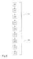
- the calibration procedure comprises the succession of the following steps: a step 101 for calculating the intrinsic parameters of the cameras TC1-TC3, a step 102 for removing the distortion, a step 103 for calculating the homographies of the reference plane, a step 104 for estimating the fusion maps and lastly a step 105 for estimating the maps for the photometric normalization.
- the calibration procedure is only performed once, in the installation step.
- the frames of interest are:
- the top view allows a global view of the scene, on the other it determines a perspective deformation of the objects which may cause difficulties in interpreting the scene for the operator.
- the use of some other views allows this problem to be obviated in the event these difficulties arise.
- Step 101 comprises the calculation of the intrinsic parameters of cameras TC1-TC3 by means of a calibration algorithm known in literature, by acquiring a series of images from a "planar grid” (known e.g. from the article " Flexible Camera Calibration by Viewing a Plane from Unknown Orientations", Zhang, in Proceedings of the International Conference on Computer Vision, pp. 666-673, 1999 ).
- the intrinsic parameters of the cameras comprise the focal length, the main point and the distortion parameters.
- the calculation of the intrinsic parameters may also be performed prior to the installation of the apparatus on the ship and thus might not be performed by the application software installed in memory 27 of device 20.
- the distortion may be removed in such a way that the relation linking points of the three-dimensional world and image points may be expressed, according to the "pinhole geometrical model” (known e.g. from the book “ Multiple View Geometry in Computer Vision”, Hartley and Zisserman, pp. 153-156, Cambridge University Press, 2004 ), by means of a matrix known as "of projection”.
- step 102 the distortion is modelled by means of a non-linear transformation of the ideal coordinates (not distorted) into the notable true coordinates (distorted).
- a scan of the non-distorted destination image allows the distortion of the image acquired by cameras TC1-TC3 to be compensated for.
- Step 102 may also be performed also prior to the installation of the apparatus on the ship and thus might not be performed by the application software installed in memory 27 of device 20.
- Step 103 comprises the calculation of the homographies of the reference plane; step 103 is performed by the application software installed in memory 27 of device 20.
- step 103 is performed by the application software installed in memory 27 of device 20.
- the pinhole geometrical model it is known from literature that a plane in space and the perspective image thereof are linked by a linear relation called homography. Given the homography, it is possible to generate a new summary view of the plane from an arbitrary point of view. The result is equivalent to placing a virtual camera in that point, thus generating a virtual image or view.
- the calculation of the homographies with respect to the reference plane requires the assistance of a planar chessboard (calibration grid) that is large enough to be seen in all the cameras.
- the homography of one spatial plane is calculated with a group of relations (at least 4) of three-dimensional points (3D) of the plane and points in the image.
- the grid should be placed on the spatial plane intended to be used (hence the plane of platform 25, for example). Due to auto-obstructions, the grid might not be viewed by all the cameras. To obviate this problem, the following solution is implemented: the calibration grid is positioned on a planes ⁇ r which is visible to all cameras TC1-TC3 and the homography H r of that plane is estimated for all cameras.
- the 3x4 projection matrix of the camera indicates how the 3D points are projected in the image.
- the reference planes are the plane of the platform, the common image plane of the cameras arranged parallel and at the same height (TC1 and TC2) and the image plane itself of the individual camera (TC3), respectively.
- the superimposition between views is not such to be able to display a same common grid for all the cameras TC1-TC3
- it is possible to extend the above-described system thus determining the homography of all cameras with respect to a different convenient spatial plane to be estimated and i.e. the planes ⁇ TC1 , ⁇ TC2 , ⁇ TC3 . Knowing the spatial relation of these planes with respect to the reference plane ⁇ d , the homographies are transformed so that they are directly mapped on plane ⁇ d .
- the use of the calibration grid is entirely eliminated.
- a "structure-and-motion" algorithm is used which allows the position to be obtained of the cameras with respect to the ship (motion) and a three-dimensional reconstruction by points (structure) of the framed scene. The homographies may be directly calculated with this information and if the position of the planes of interest with respect to the ship is known.
- the homographies of a plane itself in space deriving from various cameras may be used for mapping various views in a single view (planar mosaic), thus obtaining an enlargement of the global visual field from the desired point of view. Since the cameras are fixed, once the homographies of the plane have been calculated and how the views merge to form the final view has been established, i.e. the fusion map has been established, the relation that maps the individual views in the single view remains constant.
- Step 104 comprises the estimation of the fusion maps which, in the rendering step 200, allow the summary views to be generated in real time; step 104 is performed by the application software installed in memory 27 of device 20.
- the chosen configuration results in the virtual view being exactly parallel to the plane at a distance Dh for the plane of the platform, for the common image plane of the cameras arranged parallel and at the same height (TC1 and TC2) and the image plane itself of the individual camera (TC3).
- the orthographical view is the top view and merges together the informative contents of all the cameras.
- This information constitutes the fusion map M, which will be specific for all rendering modes.
- the map allows the summary views to be generated for the different views by directly using the video flows (hence without having to remove the distortion).
- Step 105 that is the estimation of the fusion maps for the photometric normalization, allows any brightness differences to be corrected between the video flows; step 105 is performed by the application software installed in memory 27 of device 20.
- step 105 it is required to determine the multiplicative gain factors ⁇ i to be applied to the images so that these appear with the same brightness.
- This estimation is to be performed in the rendering step, since the brightness varies based on the lighting conditions.
- the coordinates are registered of a common periphery area between all the various cameras, i.e.
- the corresponding distorted coordinates u, v are registered for all images deriving from cameras TC1-TC3.
- the obtained map allows the pixels for all images belonging to this area of intersection to be quickly recovered in the rendering step, to be used for estimating the gain factors.
- the rendering procedure 200 is performed by the application software installed in memory 27 of device 20 and comprises the following steps: a step 201 for the synchronized acquisition of the video flows from all the cameras, a step 202 in which, by using the fusion map for the photometric normalization, the average brightness is determined of all cameras and the gain factors ⁇ i are calculated which allow the cameras to be arranged at the same brightness by using one as a reference, a step 203 in which, on the basis of the selected rendering mode, the corresponding fusion map is selected and a step 204 in which image Io is formed by considering the values of the pixels from the corresponding video flows, on the basis of what is registered in the fusion map and of the gain factors ⁇ i .
Landscapes
- Chemical & Material Sciences (AREA)
- Engineering & Computer Science (AREA)
- Combustion & Propulsion (AREA)
- Mechanical Engineering (AREA)
- Ocean & Marine Engineering (AREA)
- Image Processing (AREA)
- Ceramic Products (AREA)
Abstract
Description
- The present invention relates to an assisting visual apparatus for mooring a ship.
- The difficulties are known for performing a manoeuvre for mooring a ship, in particular the manoeuvre for stern mooring, due to the difficulties in identifying some obstacles and in estimating the volumes of the ship which is being manoeuvred due to poor visibility of the stern from the governing stations. The most difficult step in the manoeuvre for mooring is the approach and the alignment with the berth. The simple installation of a camera and associated viewer that shows the ship stern and the quay to which the ship is nearing, is not capable of displaying the ship volumes.
- In view of the state of the art, it is the object of the present invention to provide an assisting visual apparatus for mooring a ship.
- In accordance with the present invention, said object is achieved by means of an assisting visual apparatus for mooring a ship, said apparatus comprising at least one pair of shooting means arranged at given heights on the ship so as to have a visual field spanning the part surrounding the ship stern and a part of the same ship, an image control device comprising a memory, a data processing unit and an application software, and it being adapted to combine the single images shot by the shooting means, a display on which the final image processed by the image control device is displayed in real time, characterized in that said application software of the image control device comprises a calibration function of the shooting means which includes, for all shooting means, the calculation of the homographies with respect to a selected reference plane, the generation of a virtual image as combination of the single images deriving from the shooting means on the base of the calculated homographies, the formation of at least one fusion map on the base of the virtual image, said application software comprising a successive function of rendering including the formation of the final image to be displayed on the display as a function of said at least one fusion map.
- Due to the present invention, it is possible to provide an assisting visual apparatus for mooring a ship which allows the operator to be shown the largest view possible of the stern zone, by merging the views acquired by a group of cameras. The system allows the nearing of the ship to the quay and the presence of any other ships or obstacles of another kind in the planned trajectory, to be monitored. The system helps the operator to prevent the corners of the ship from knocking against other ships and to stop at an adequate distance from the quay during the mooring.
- The features and advantages of the present invention will become apparent from the following detailed description of a practical embodiment thereof, shown by way of non-limiting example in the accompanying drawings, in which:
-
figure 1 is a diagrammatic top view of the manoeuvre for mooring a ship equipped with an assisting visual apparatus for mooring in accordance with the present invention; -
figure 2 shows an assisting visual apparatus for mooring a ship in accordance with the present invention; -
figures 3-4 are views of a ship equipped with the apparatus in accordance with the present invention; -
figure 5 is a block diagram of the various steps of the calibration and rendering procedure performed by the assisting visual apparatus for mooring a ship in accordance with the present invention; -
figure 6 shows the combination of two images with the apparatus in accordance with the present invention; -
figure 7 shows the combination of three images with the apparatus in accordance with the present invention. -
Figure 1 diagrammatically shows a ship in mooring manoeuvre, whereinship 1 is equipped with an assisting visual apparatus for mooring in accordance with the present invention.Ship 1 is to be arranged near quay 3 betweenships visual angle 2 with respect to the one of a simple camera arranged on the stern ofship 1. - The assisting visual apparatus for mooring
ship 1 is best seen infigure 2 . The apparatus comprises at least two shooting means, preferably three cameras TC1-TC3 arranged onship 1, oneimage control device 20 powered by apower source 21, having as input the images provided by cameras TC1-TC3 by means of a video cable and that can be activated by means of anexternal button 23. Theimage control device 20 is adapted to display images on an on-board display 24. Alternatively to display 24, it is possible to use a dedicated display mounted up high, such as a rear-view mirror, to prevent hindrances during the manoeuvre for mooring. - The
image control device 20 is for applying the required transformations to the images deriving from the group of cameras TC1-TC3 and is adapted to perform the transfer of the processed video image (video output) on the available on-board navigation display 24. Theimage control device 20 has acontrol 25 for allowing the operator to select one of the available operating modes.Device 20 includes adata processing unit 28 and amemory 27 on which an application software is installed and operating;device 20 is configured in such a way to perform the transformations of the images in real time. - Cameras TC1-TC3 shoot, in real time, the frame towards which they have been set up and send the shot frames to
device 20, in real time. - A possible arrangement of cameras TC1-TC3 on
ship 1 is shown infigures 3-4 . The cameras TC1 and TC2 are mounted onship 1 at the same height H and with the same vertical tilt G at a distance D from each other, while camera TC3 is positioned at a lower height H3 and so as to directly frame platform 11 ofship 1. The arrangement of cameras TC1-TC3 ensures that an area about the ship is framed without obstructions obstructing the view of the periphery ofship 1 itself, by merging the video flows of all the cameras. - The assisting visual apparatus for mooring in accordance with the invention provides a
calibration procedure 100, to be performed during the installation, and arendering procedure 200, in real time, which may comprise three various modes together or alternatively with each other: an orthographical view or top view, fusion of all the cameras (TC1, TC2, TC3), a perspective view, merging of two cameras (TC1, TC2) and a direct view, from one camera (TC3). In particular, certain or all the steps in thecalibration procedure 100 andrendering procedure 200 are performed by the application software installed inmemory 27 ofdevice 20. - The calibration procedure comprises the succession of the following steps: a
step 101 for calculating the intrinsic parameters of the cameras TC1-TC3, astep 102 for removing the distortion, astep 103 for calculating the homographies of the reference plane, astep 104 for estimating the fusion maps and lastly astep 105 for estimating the maps for the photometric normalization. The calibration procedure is only performed once, in the installation step. - For the mooring assisting, the frames of interest are:
- — a top view using the platform plane as a reference plane, union of all cameras (TC1, TC2 and TC3), such as to allow the rear and side distance from the other ships and from the quay to be visually estimated;
- — a single perspective view given by the merging of the cameras installed at the same height and with the same vertical tilt (TC1 and TC2). In this case, the reference plane is parallel to the two cameras, at a defined distance;
- — a single view (TC3) of the rear of the ship.
- If on the one hand the top view allows a global view of the scene, on the other it determines a perspective deformation of the objects which may cause difficulties in interpreting the scene for the operator. The use of some other views allows this problem to be obviated in the event these difficulties arise.
-
Step 101 comprises the calculation of the intrinsic parameters of cameras TC1-TC3 by means of a calibration algorithm known in literature, by acquiring a series of images from a "planar grid" (known e.g. from the article " Flexible Camera Calibration by Viewing a Plane from Unknown Orientations", Zhang, in Proceedings of the International Conference on Computer Vision, pp. 666-673, 1999). The intrinsic parameters of the cameras comprise the focal length, the main point and the distortion parameters. The calculation of the intrinsic parameters may also be performed prior to the installation of the apparatus on the ship and thus might not be performed by the application software installed inmemory 27 ofdevice 20. - Once the intrinsic parameters are known, the distortion may be removed in such a way that the relation linking points of the three-dimensional world and image points may be expressed, according to the "pinhole geometrical model" (known e.g. from the book " Multiple View Geometry in Computer Vision", Hartley and Zisserman, pp. 153-156, Cambridge University Press, 2004), by means of a matrix known as "of projection".
- In
step 102, the distortion is modelled by means of a non-linear transformation of the ideal coordinates (not distorted) into the notable true coordinates (distorted). By means of a known system such as "backward mapping" (e.g. known from the book " Digital Image Warping", Wolberg, p. 43, Wiley-IEEE Computer Society Press, 1990), a scan of the non-distorted destination image allows the distortion of the image acquired by cameras TC1-TC3 to be compensated for.Step 102 may also be performed also prior to the installation of the apparatus on the ship and thus might not be performed by the application software installed inmemory 27 ofdevice 20. -
Step 103 comprises the calculation of the homographies of the reference plane;step 103 is performed by the application software installed inmemory 27 ofdevice 20. According to the pinhole geometrical model, it is known from literature that a plane in space and the perspective image thereof are linked by a linear relation called homography. Given the homography, it is possible to generate a new summary view of the plane from an arbitrary point of view. The result is equivalent to placing a virtual camera in that point, thus generating a virtual image or view. - In accordance with an embodiment of the invention, the calculation of the homographies with respect to the reference plane requires the assistance of a planar chessboard (calibration grid) that is large enough to be seen in all the cameras. The homography of one spatial plane is calculated with a group of relations (at least 4) of three-dimensional points (3D) of the plane and points in the image. The grid should be placed on the spatial plane intended to be used (hence the plane of
platform 25, for example). Due to auto-obstructions, the grid might not be viewed by all the cameras. To obviate this problem, the following solution is implemented: the calibration grid is positioned on a planes πr which is visible to all cameras TC1-TC3 and the homography Hr of that plane is estimated for all cameras. - The 3x4 projection matrix of the camera indicates how the 3D points are projected in the image. According to the pinhole model, said matrix has the shape P = K [R t] , where K is the 3x3 matrix of the intrinsic parameters and R = [r1 r2 r3] and t are the 3x3 rotation matrix and the 3x1 translation vector, respectively, which indicate the position of the camera with respect to the reference system. By fixing the reference on the plane and assuming that said plane has the equation Z=0, homography Hr of plane π r estimated using the calibration grid may hence be expressed according to the equation Hr = K [r1 r2 t].
- Writing Hr = [h1 h2 h3] obtains r1 = K -1h1 and r2 = K -1h2; r3 is estimated while considering the constraint of orthogonality of r3 with respect to the plane determined by r1 and r2 (R is composed of orthonormal columns as it is a rotation matrix, ), that is r3 = (r1 x r2). Given H r , the projection matrix P is hence now capable of being obtained.
- Knowing the spatial relation (the roto-translation in the 3D space) between π r and the plane π d of interest, it is possible to transform these homographies so that they are mapped on π d instead of on π r .
- Being

- This allows the calculation of the homography to be performed for one individual plane, on which the calibration grid is clearly visible from all the cameras, and then to transform them into homographies with respect to any other spatial plane. Based on the required points of view, the reference planes are the plane of the platform, the common image plane of the cameras arranged parallel and at the same height (TC1 and TC2) and the image plane itself of the individual camera (TC3), respectively.
- In accordance with a variant of the embodiment of the invention, if the superimposition between views is not such to be able to display a same common grid for all the cameras TC1-TC3, it is possible to extend the above-described system thus determining the homography of all cameras with respect to a different convenient spatial plane to be estimated and i.e. the planes πTC1, πTC2, πTC3. Knowing the spatial relation of these planes with respect to the reference plane πd, the homographies are transformed so that they are directly mapped on plane πd.
- In accordance with another variant of the embodiment of the invention, the use of the calibration grid is entirely eliminated. A "structure-and-motion" algorithm is used which allows the position to be obtained of the cameras with respect to the ship (motion) and a three-dimensional reconstruction by points (structure) of the framed scene. The homographies may be directly calculated with this information and if the position of the planes of interest with respect to the ship is known.
- Similarly to the formation of planar mosaics, the homographies of a plane itself in space deriving from various cameras may be used for mapping various views in a single view (planar mosaic), thus obtaining an enlargement of the global visual field from the desired point of view. Since the cameras are fixed, once the homographies of the plane have been calculated and how the views merge to form the final view has been established, i.e. the fusion map has been established, the relation that maps the individual views in the single view remains constant.
- Step 104 comprises the estimation of the fusion maps which, in the
rendering step 200, allow the summary views to be generated in real time;step 104 is performed by the application software installed inmemory 27 ofdevice 20. - There is a need to establish the position of the virtual camera with respect to the reference plane. The chosen configuration results in the virtual view being exactly parallel to the plane at a distance Dh for the plane of the platform, for the common image plane of the cameras arranged parallel and at the same height (TC1 and TC2) and the image plane itself of the individual camera (TC3). The orthographical view is the top view and merges together the informative contents of all the cameras. The desired specifications to be displayed relating to the area about the ship and the distance between the stern end of
ship 1 and the halfway point of the distance between camera TC3 and the straight line joining cameras TC1 and TC2 allow distance Dh to be defined to arrange the virtual camera to display the virtual visual field. In the case of image plane of the individual camera, distance Dh=0. - Given the dimension w x h of the virtual view Iout (the planar mosaic):
- — Iout is divided into regions Rtc1, Rtc2, Rtc3 thus establishing for all regions, on the basis of the position of the cameras, which video flow to show.
Figures 6 and 7 show the division in the case of the perspective view and of the orthographical view; - — an edge of pixel dimension b is defined, at the periphery of the regions, which depicts the fusion area between various views. In
figures 6 and 7 , the dotted edge shows the periphery zone; - — a weight mask F is formed, which assigns variable values between 0.5 and 1 to the edge zones and value equal to 1 to the remaining zones.
- For all x, y positions in the planar mosaic or virtual view Iout, the following is registered in the fusion map M:
- — the region to which the pixel belongs, i.e. camera TCi that sees that area;
- — coordinates u, v in the image deriving from camera TCi, corresponding to x, y: first, the inverted homography is applied to determine position u', v' in the non-distorted image deriving from camera TCi, then the distortion to determine position u, v in the original distorted image deriving from camera TCi;
- — if F (x, y) is other than 1, i.e. we are on the edge at the periphery between the images deriving from two different cameras TCi and TCj, the coordinates h, k in the image deriving from camera TCj corresponding to x, y are to be calculated as previously described.
- Lastly, the virtual view Iout is reflected with respect to the central axis of the image, to facilitate the reversing of the ship.
- This information constitutes the fusion map M, which will be specific for all rendering modes. The map allows the summary views to be generated for the different views by directly using the video flows (hence without having to remove the distortion).
-
Step 105, that is the estimation of the fusion maps for the photometric normalization, allows any brightness differences to be corrected between the video flows;step 105 is performed by the application software installed inmemory 27 ofdevice 20. For the photometric normalization, it is required to determine the multiplicative gain factors α i to be applied to the images so that these appear with the same brightness. This estimation is to be performed in the rendering step, since the brightness varies based on the lighting conditions. To avoid estimating the brightness of an image using all the pixels in that image, the coordinates are registered of a common periphery area between all the various cameras, i.e. for all points of coordinates x, y in aforesaid area, the corresponding distorted coordinates u, v are registered for all images deriving from cameras TC1-TC3. The obtained map allows the pixels for all images belonging to this area of intersection to be quickly recovered in the rendering step, to be used for estimating the gain factors. - The
rendering procedure 200, successive to thecalibration procedure 100, is performed by the application software installed inmemory 27 ofdevice 20 and comprises the following steps: astep 201 for the synchronized acquisition of the video flows from all the cameras, astep 202 in which, by using the fusion map for the photometric normalization, the average brightness is determined of all cameras and the gain factors α i are calculated which allow the cameras to be arranged at the same brightness by using one as a reference, astep 203 in which, on the basis of the selected rendering mode, the corresponding fusion map is selected and astep 204 in which image Io is formed by considering the values of the pixels from the corresponding video flows, on the basis of what is registered in the fusion map and of the gain factors α i .
Claims (9)
- Assisting visual apparatus for mooring a ship (1), said apparatus comprising at least one pair of shooting means (TC1-TC3) arranged a given heights (H1, H2) on the ship so as to have a visual field spanning the part surrounding the ship stern and a part of the same ship, an image control device (20) comprising a memory (27), a data processing unit (28) and an application software and it being adapted to combine the single images shoot by the shooting means (TC1-TC3), a display (24) on which the final image (Io) processed by the image control device is displayed in real time, characterized in that said application software of the image control device comprises a calibration function (100) of the shooting means which includes, for each shooting means, the calculation (103) of the homographies with respect to the selected reference plane (πd), the generation of a virtual image (Iout) as combination of the single images deriving from the shooting means on the base of the calculated homographies, the formation of at least one fusion map (M) on the base of the virtual image (Iout), said software comprising a successive function of rendering (200) including the formation of the final image (Io) which has to be displayed on the display as a function of said at least one fusion map (M).
- Apparatus according to claim 1, characterised in that said shooting means of said pair of shooting means (TC1-TC3) are arranged at equal height on the ship.
- Apparatus according to claim 1, characterised by comprising at least three shooting means, two shooting means (TC1-TC2) are arranged at equal height on the ship and the other shooting means (TC3) is arranged at a different height on the ship.
- Apparatus according to claim 1, characterised in that said calibration function (100) comprises, after the calculation of the intrinsic parameters of the shooting means (101) and the removal of the distortion in the images deriving from the shooting means (102), said calculation (103) of the homographies with respect to the selected reference plane (πd), the formation of at least one fusion map (M) and the estimation of the maps for the photometric normalization (105).
- Apparatus according to claim 4, characterised in that said calculation (103) of the homographies with respect to the selected reference plane (πd) comprises the assistance of a calibration grid arranged on a further plane (πr) which is visible to all the shooting means, the calculation of the homographies with respect to said further plane (πr) in which the calibration grid is visible and the transformation of the calculated homographies into homographies with respect to the reference plane (πd).
- Apparatus according to claim 4, characterised in that said calculation (103) of the homographies with respect to the selected reference plane (πd) comprises the determination of the homography of each shooting means with respect to a respective spatial plane (πTC1, πTC2, πTC3) and the transformation of all the homographies so as to map them on the selected reference plane (πd).
- Apparatus according to claim 4, characterised in that the formation of a fusion map (M) comprises the determination of the position of the virtual shooting means with respect to the reference plane, the division of the virtual image (Iout), which derives from the virtual shooting means, into regions (Rtc1, Rtc2, Rtc3) by stabilizing for each region, on the base of the position of the shooting means (TC1-TC3), which image deriving from the shooting means (TC1-TC3) must be showed, the definition of an edge (b) in the periphery of said regions which represents the fusion area of the different images deriving from the shooting means and the formation of a weight mask (F) which assigns values comprises between 0.5 and 1 to the zones next to the edge and value 1 to the remaining zones, the registration of the region to which the pixel belongs for each planar position of the pixel (x, y) of the virtual image (Iout), the determination of the coordinates (u, v), in the image deriving from the shooting means, which correspond to the planar position of the pixel (x, y) by applying first the inverted homography for determining the position (u', v') in the non-distorted image and then applying the distortion for determining the position (u, v) in the original distorted image, the application to the virtual image of the reflection with respect to the central axis of the virtual image.
- Apparatus according to claim 7, characterised in that the estimation of the maps for the photometric normalization comprises the determination of a superimposition area of regions belonging to images deriving from different shooting means and the registration, for each pixel of this area, of the corresponding coordinates (u, v) of each distorted image deriving from the respective shooting means, said estimation being used for the calculation of the gain factors (αi) for each shooting means.
- Apparatus according to claim 1, characterised in that said rendering function comprises the synchronized acquisition of the images deriving from the shooting means, the determination of the medium brightness of each shooting means in the base of the fusion map for the photometric normalization which has been used and the calculation of the multiplicative gain factors (α i ) which allow to arrange the shooting means (TC1-TC3) at the same brightness, the formation of the final image (Io) as a function of the values of the pixels deriving from the shooting means on the base of the fusion map (M) and said calculated gain factors (α i ).
Applications Claiming Priority (1)
| Application Number | Priority Date | Filing Date | Title |
|---|---|---|---|
| ITMI2010A001737A IT1401965B1 (en) | 2010-09-24 | 2010-09-24 | ASSISTANCE DEVICE VISUALIZED AT THE MOORING OF A BOAT. |
Publications (1)
| Publication Number | Publication Date |
|---|---|
| EP2441660A1 true EP2441660A1 (en) | 2012-04-18 |
Family
ID=43738945
Family Applications (1)
| Application Number | Title | Priority Date | Filing Date |
|---|---|---|---|
| EP11182355A Withdrawn EP2441660A1 (en) | 2010-09-24 | 2011-09-22 | Assisting visual apparatus for mooring a ship |
Country Status (2)
| Country | Link |
|---|---|
| EP (1) | EP2441660A1 (en) |
| IT (1) | IT1401965B1 (en) |
Cited By (4)
| Publication number | Priority date | Publication date | Assignee | Title |
|---|---|---|---|---|
| CN110879599A (en) * | 2019-12-12 | 2020-03-13 | 大连海事大学 | Fixed time formation control method based on finite time disturbance observer |
| CN113450597A (en) * | 2021-06-09 | 2021-09-28 | 浙江兆晟科技股份有限公司 | Ship auxiliary navigation method and system based on deep learning |
| JP2022114274A (en) * | 2021-01-26 | 2022-08-05 | 三菱重工業株式会社 | Aboardage support system and aboardage support method |
| EP4468023A1 (en) | 2023-05-20 | 2024-11-27 | Yamaha Hatsudoki Kabushiki Kaisha | Sensor assembly for watercraft, operation support system and watercraft |
Citations (1)
| Publication number | Priority date | Publication date | Assignee | Title |
|---|---|---|---|---|
| US20070073454A1 (en) * | 2005-09-15 | 2007-03-29 | Yamaha Hatsudoki Kabushiki Kaisha | Docking supporting apparatus, and marine vessel including the apparatus |
-
2010
- 2010-09-24 IT ITMI2010A001737A patent/IT1401965B1/en active
-
2011
- 2011-09-22 EP EP11182355A patent/EP2441660A1/en not_active Withdrawn
Patent Citations (1)
| Publication number | Priority date | Publication date | Assignee | Title |
|---|---|---|---|---|
| US20070073454A1 (en) * | 2005-09-15 | 2007-03-29 | Yamaha Hatsudoki Kabushiki Kaisha | Docking supporting apparatus, and marine vessel including the apparatus |
Non-Patent Citations (4)
| Title |
|---|
| HARTLEY, ZISSERMAN: "Multiple View Geometry in Computer Vision", 2004, CAMBRIDGE UNIVERSITY PRESS, pages: 153 - 156 |
| HARTLEY, ZISSERMAN: "Multiple View Geometry in Computer Vision", 2004, CAMBRIDGE UNIVERSITY PRESS, pages: 196 |
| WOLBERG: "Digital Image Warping", 1990, WILEY-IEEE COMPUTER SOCIETY PRESS, pages: 43 |
| ZHANG: "Flexible Camera Calibration by Viewing a Plane from Unknown Orientations", PROCEEDINGS OF THE INTERNATIONAL CONFERENCE ON COMPUTER VISION, 1999, pages 666 - 673, XP010350391 |
Cited By (5)
| Publication number | Priority date | Publication date | Assignee | Title |
|---|---|---|---|---|
| CN110879599A (en) * | 2019-12-12 | 2020-03-13 | 大连海事大学 | Fixed time formation control method based on finite time disturbance observer |
| JP2022114274A (en) * | 2021-01-26 | 2022-08-05 | 三菱重工業株式会社 | Aboardage support system and aboardage support method |
| CN113450597A (en) * | 2021-06-09 | 2021-09-28 | 浙江兆晟科技股份有限公司 | Ship auxiliary navigation method and system based on deep learning |
| CN113450597B (en) * | 2021-06-09 | 2022-11-29 | 浙江兆晟科技股份有限公司 | Ship auxiliary navigation method and system based on deep learning |
| EP4468023A1 (en) | 2023-05-20 | 2024-11-27 | Yamaha Hatsudoki Kabushiki Kaisha | Sensor assembly for watercraft, operation support system and watercraft |
Also Published As
| Publication number | Publication date |
|---|---|
| ITMI20101737A1 (en) | 2012-03-25 |
| IT1401965B1 (en) | 2013-08-28 |
Similar Documents
| Publication | Publication Date | Title |
|---|---|---|
| JP7245295B2 (en) | METHOD AND DEVICE FOR DISPLAYING SURROUNDING SCENE OF VEHICLE-TOUCHED VEHICLE COMBINATION | |
| CN112224132B (en) | Vehicle panoramic all-around obstacle early warning method | |
| JP3286306B2 (en) | Image generation device and image generation method | |
| JP7295123B2 (en) | Surround view system with adjusted projection plane | |
| JP4257356B2 (en) | Image generating apparatus and image generating method | |
| US8295644B2 (en) | Birds eye view virtual imaging for real time composited wide field of view | |
| JP4642723B2 (en) | Image generating apparatus and image generating method | |
| US20090022423A1 (en) | Method for combining several images to a full image in the bird's eye view | |
| US11087438B2 (en) | Merging of partial images to form an image of surroundings of a mode of transport | |
| JP2002135765A (en) | Camera calibration instruction device and camera calibration device | |
| CN109948398A (en) | The image processing method and panorama parking apparatus that panorama is parked | |
| US10460428B2 (en) | Method, head-up display and output system for the perspective transformation and outputting of image content, and vehicle | |
| CN107438538A (en) | Method for displaying vehicle surroundings of a vehicle | |
| US20160037154A1 (en) | Image processing system and method | |
| JP4248570B2 (en) | Image processing apparatus and visibility support apparatus and method | |
| WO2018221209A1 (en) | Image processing device, image processing method, and program | |
| CN113840755B (en) | Method for generating vehicle surrounding environment image and device for generating vehicle surrounding environment image | |
| JP2008048317A (en) | Image processing unit, and sight support device and method | |
| ITMI20101737A1 (en) | ASSISTANCE DEVICE VISUALIZED AT THE MOORING OF A BOAT. | |
| JP2010218058A (en) | Device and method for supporting driving | |
| CN110428361A (en) | A kind of multiplex image acquisition method based on artificial intelligence | |
| JP2016213759A (en) | Rear monitor | |
| CN115968485A (en) | Method for displaying a vehicle environment on a display device, processing unit and vehicle | |
| JP2006080626A (en) | Wide-angle image correction method and vehicle periphery monitoring system | |
| JP4650935B2 (en) | Vehicle driving support device |
Legal Events
| Date | Code | Title | Description |
|---|---|---|---|
| PUAI | Public reference made under article 153(3) epc to a published international application that has entered the european phase |
Free format text: ORIGINAL CODE: 0009012 |
|
| 17P | Request for examination filed |
Effective date: 20110922 |
|
| AK | Designated contracting states |
Kind code of ref document: A1 Designated state(s): AL AT BE BG CH CY CZ DE DK EE ES FI FR GB GR HR HU IE IS IT LI LT LU LV MC MK MT NL NO PL PT RO RS SE SI SK SM TR |
|
| AX | Request for extension of the european patent |
Extension state: BA ME |
|
| RAP1 | Party data changed (applicant data changed or rights of an application transferred) |
Owner name: EVS EMBEDDED VISION SYSTEMS S.R.L. |
|
| GRAP | Despatch of communication of intention to grant a patent |
Free format text: ORIGINAL CODE: EPIDOSNIGR1 |
|
| INTG | Intention to grant announced |
Effective date: 20130415 |
|
| STAA | Information on the status of an ep patent application or granted ep patent |
Free format text: STATUS: THE APPLICATION IS DEEMED TO BE WITHDRAWN |
|
| 18D | Application deemed to be withdrawn |
Effective date: 20130827 |