EP2441357A1 - Led coaster - Google Patents
Led coaster Download PDFInfo
- Publication number
- EP2441357A1 EP2441357A1 EP10786111A EP10786111A EP2441357A1 EP 2441357 A1 EP2441357 A1 EP 2441357A1 EP 10786111 A EP10786111 A EP 10786111A EP 10786111 A EP10786111 A EP 10786111A EP 2441357 A1 EP2441357 A1 EP 2441357A1
- Authority
- EP
- European Patent Office
- Prior art keywords
- led
- switch
- bottom cover
- cover
- coaster
- Prior art date
- Legal status (The legal status is an assumption and is not a legal conclusion. Google has not performed a legal analysis and makes no representation as to the accuracy of the status listed.)
- Withdrawn
Links
Images



Classifications
-
- A—HUMAN NECESSITIES
- A47—FURNITURE; DOMESTIC ARTICLES OR APPLIANCES; COFFEE MILLS; SPICE MILLS; SUCTION CLEANERS IN GENERAL
- A47G—HOUSEHOLD OR TABLE EQUIPMENT
- A47G23/00—Other table equipment
- A47G23/03—Underlays for glasses or drinking-vessels
- A47G23/0306—Underlays for glasses or drinking-vessels with means for amusing or giving information to the user
- A47G23/0309—Illuminated
-
- F—MECHANICAL ENGINEERING; LIGHTING; HEATING; WEAPONS; BLASTING
- F21—LIGHTING
- F21V—FUNCTIONAL FEATURES OR DETAILS OF LIGHTING DEVICES OR SYSTEMS THEREOF; STRUCTURAL COMBINATIONS OF LIGHTING DEVICES WITH OTHER ARTICLES, NOT OTHERWISE PROVIDED FOR
- F21V33/00—Structural combinations of lighting devices with other articles, not otherwise provided for
- F21V33/0004—Personal or domestic articles
- F21V33/0024—Household or table equipment
- F21V33/0036—Table-ware or table equipment, e.g. dishes, cutlery or trays
-
- F—MECHANICAL ENGINEERING; LIGHTING; HEATING; WEAPONS; BLASTING
- F21—LIGHTING
- F21Y—INDEXING SCHEME ASSOCIATED WITH SUBCLASSES F21K, F21L, F21S and F21V, RELATING TO THE FORM OR THE KIND OF THE LIGHT SOURCES OR OF THE COLOUR OF THE LIGHT EMITTED
- F21Y2115/00—Light-generating elements of semiconductor light sources
- F21Y2115/10—Light-emitting diodes [LED]
Definitions
- the present invention relates to a coaster on which a cup, such as a glass, containing a beverage, such as alcohol, soft drinks, water, etc. is rested and, particularly, to a LED coaster capable of illuminating a cup from the bottom in order to create a comfortable atmosphere, particularly when people enjoy eating and drinking.
- a cup such as a glass
- a beverage such as alcohol, soft drinks, water, etc.
- Fig. 9 is a top view of the LED coaster 110.
- Fig. 10 is a bottom view showing the conventional LED coaster 110.
- Fig. 11 is a side view of the conventional LED coaster 110.
- Fig. 12 is a side view where the conventional LED coaster 110 has been placed on e.g. a table.
- Fig. 13 is a side view where the conventional LED coaster 110 has been placed on e.g. a table and a cup containing a beverage has been put on the coaster.
- the conventional LED coaster 110 has a circular light transmitting cover 101 on its upper surface (on which a cup is rested), and an upper-surface circumferential cover 102 is provided to cover the upper-surface outer periphery of the light transmitting cover 101.
- the light transmitting cover 101 is not entirely transparent but has a transparent light transmitting part 101a formed approximately at the center of its upper surface and a transparent light transmitting part 101b formed on its side surface. Through these light transmitting parts 101a and 101b, the light from the LED (light emitting diode) is transmitted to the outside.
- the LED is arranged on the inside (reverse side) of the light transmitting part 101a, so that the LED faces the light transmitting part 101a.
- the LED is to be placed approximately at the center of the LED coaster 110.
- the LED is mounted on a non-illustrated substrate.
- the bottom surface of the LED coaster 110 comprises a circular bottom cover 103. In the vicinity of the outer periphery of the bottom cover 103, three rubber pads 105 are provided at approximately equal intervals. When the LED coaster 110 is placed on the table, etc., the rubber pads 105 contact the table, etc.
- a switch pad 104 for lighting the LED is provided at a position slightly off from the center of the bottom cover 103. As described above, since the LED is located approximately at the center of the LED coaster 110, the switch pad 104 is positioned slightly off from the center of the LED coaster 110 for the convenience of the layout of the substrate.
- an elongated-hole-type battery cover 106 is screwed with a screw 107.
- Two button batteries are stored on the inside (reverse side) of the battery cover 106, facing it.
- the button batteries are the power supply for the LED.
- the switch pad 104 is attached to the bottom cover 103 in a vertically moveable manner (moveable in the direction of the thickness of the LED coaster 110).
- the flange of the switch pad 104 is mounted on the (not illustrated) step portion of the circular hole in the bottom cover 103. In this state, there is a gap (play) between the switch on the substrate and the switch pad 104.
- the LED coaster 110 in its normal posture (state) is not located on e.g. a table, as shown in Fig. 11 , the relationship h2 > h1 is satisfied, where h1 designates the height of the rubber pads 105 protruding from the bottom cover 103, and h2 designates the height of the switch pad 104 protruding from the bottom cover 103.
- the weight of the LED coaster 110 is applied to the switch pad 104 which then moves into the LED coaster 110 by the gap (play) between itself and the switch on the substrate and contacts the switch on the substrate.
- the LED coaster 110 is placed on a table, etc. in such a manner that the two rubber pads 105 on the button battery side and the switch pad 104 contact the table, etc. Then, the relationship h2 > h2' > h1 is fulfilled, where h2' represents the height of the switch pad 104 protruding from the bottom cover 103.
- the switch pad 104 moves further into the LED coaster 110 because of the weight of the cup 108, etc. and presses the switch on the substrate. In this manner, the switch is operated and the LED is lit.
- the height h2" of the switch pad 104 protruding from the bottom cover 103 is still greater than the height h1 of the rubber pads 105, and the relationship h2 > h2' > h2" > h1 is satisfied.
- the rubber pads 105 opposite the button batteries float over the table. Therefore, the LED coaster 110 is in an unstable state and, in some cases, users of the LED coaster 110 may be dissatisfied.
- the LED coaster 110 becomes stable.
- the following coaster with a lighting device is suggested.
- This coaster with the lighting device is constructed in such a manner that, in order to overcome the inconvenience of a person having to turn the switch on and off, a placing table with a placing surface as its upper surface on which the cup is placed is supported by a coil spring in a vertically moveable manner.
- the elastic force of the coil spring is set to a strength that allows the placing surface to sink when a cup containing a predetermined amount or more of a beverage is placed on it.
- a printed circuit board is fixed on top of which the LED and the push switch are attached. If the cup is placed on the placing surface and the cup contains a predetermined amount or more of a beverage, the placing table sinks because of the weight of the cup and the push switch is turned on so that the LED is lit (see, e.g., Patent Document 1).
- Patent Document 1 JP Pat. Appl. Publ. No. 2006-20926
- the conventional LED coaster 110 is shown in Figs. 9 - 13 . If the cup 108, etc. containing a beverage is comparatively light, the rubber pads 105 opposite the button batteries float over the table. Therefore, the LED coaster 110 is in an unstable state (it is shaky), and in some cases, users of the LED coaster 110 may be dissatisfied.
- the present invention was made in order to solve this problem, and it provides a LED coaster that is in a stable state and not shaky, when the LED coaster is placed on a table and a cup, etc. containing a beverage is placed on the LED coaster.
- the LED coaster comprises: a light transmitting cover, on the upper surface of which an object is placed; a bottom cover attached to the lower surface of the light transmitting cover; a substrate provided between the light transmitting cover and the bottom cover, having a LED mounted on a component surface on the light transmitting cover side and having a switch that turns the LED on and off mounted on a solder surface on the bottom cover side; batteries contained in a battery storage part of the bottom cover to supply electric power to the LED; two rubber pads attached to the bottom surface of the bottom cover; and a switch pad that is attached to the inside of the bottom cover in a vertically moveable manner and on which a switch pressing part facing the switch is arranged, characterized in that the two rubber pads and the switch pad are arranged near the outer periphery of the bottom of the bottom cover at approximately equal intervals in a circumferential direction, and the diameter of the switch pad is set to just under 1/2 of the diameter of the LED coaster.
- the LED coaster according to this invention is characterized in that the LED mounted on the substrate is positioned approximately at the center of the LED coaster.
- the LED coaster according to this invention is characterized in that the light transmitting cover has light transmitting parts approximately at its center and on its side surface, through which the light of the LED is transmitted.
- the LED coaster according to the present invention is characterized in that a switch pressing part of the switch pad is arranged approximately at the center of the switch pad.
- the LED coaster according to the present invention is characterized in that the switch pressing part takes the cross shape.
- the LED coaster according to the present invention is characterized in that , in a state where the LED coaster is not placed on a table, etc., the relationship d1 > d2 is fulfilled, where d1 designates the size of the switch pad in the direction in which it protrudes outward from the bottom of the bottom cover of the switch pad, and d2 designates the size of the rubber pads in the direction in which they protrude outward from the bottom cover.
- the LED coaster according to the present invention is characterized in that the two rubber pads are arranged at an interval of about 120 degrees, with the battery storage part of the bottom cover lying between the rubber pads.
- the LED coaster according to the present invention is characterized in that the battery storage part of the bottom cover is formed as a concave portion which is a convex portion when seen from the inside of the bottom cover and, after the batteries are stored in the battery storage part, the battery storage part is closed with the battery cover.
- the LED coaster according to the present invention is characterized in that holes in the protruding part of the switch pad are guided to a plurality of pins set up on the reverse side of the bottom cover, so that the switch pad can move in a direction of the thickness of the LED coaster.
- the LED coaster according to the present invention is characterized in that the two rubber pads and the switch pad are arranged near the outer periphery of the bottom of the bottom cover at approximately equal intervals in the circumferential direction, and that the diameter of the switch pad is set to just under 1/2 of the diameter of the LED coaster, so that it is possible to provide a LED coaster that is in a stable state and not shaky when it is placed on the table and the cup, etc. containing a beverage is placed on it.
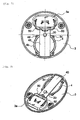
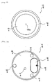
- Fig. 1 shows Embodiment 1 and is a top view of the LED coaster 10.
- Figs. 1 - 8 show Embodiment 1.
- Fig. 1 is a top view of the LED coaster 10.
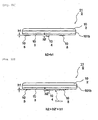
- Fig. 2 is a side view of the LED coaster 10.
- Fig. 3 is a bottom view of the LED coaster 10.
- Fig. 4 is a perspective view of the LED coaster 10 as seen from the bottom side.
- Fig. 5 is a sectional view taken along the A - A line in Fig. 3 .
- Fig. 6 is a sectional view taken along the B - B line in Fig. 3 .
- Fig. 7 is a plane view of the inside of the LED coaster 10 with the light transmitting cover 1 removed.
- Fig. 8 is a perspective view of the inside of the LED coaster 10 with the light transmitting cover 1 removed.
- the upper surface (upper portion) of the LED coaster 10 is the same as the one of the conventional LED coaster 110.
- the LED coaster 10 has the circular, plastic light transmitting cover 1 on its upper surface (on which an object, e.g., a cup, is placed) and it has an upper surface circumferential cover 2 that covers the outer peripheral part of the upper surface of the light transmitting cover 1.
- the light transmitting cover 1 is not entirely transparent but has a transparent light transmitting part 1a formed approximately at the center of its upper surface and a transparent light transmitting part 1b (see Fig. 2 ) formed on its side surface. From these light transmitting parts 1a and 1b, the light of the LED (light emitting diode) is transmitted to the outside.
- the bottom of the LED coaster 10 comprises the circular bottom cover 3.
- two rubber pads 5 and one switch pad 4 with a large diameter are provided (see Fig. 3 ).
- the LED coaster 10 in the present embodiment differs from the conventional LED coaster 110 as follows:
- the two rubber pads 5 are arranged at an interval of about 120 degrees, with the battery cover 6 of the bottom of the bottom cover 3 lying between these pads.
- the one switch pad 4 with the large diameter is arranged inside a hole 3e in the bottom cover 3 near the outer periphery on the side opposite to the battery cover 6 of the bottom of the bottom cover 3, approximately in the middle between the two rubber pads 5 (about 120 degrees).
- the LED coaster 10 When placed on a table, etc., the LED coaster 10 is supported by the table, etc. at three points, i.e. the two rubber pads 5 provided near the outer periphery of the bottom of the bottom cover 3, and the one switch pad 4 having the large diameter. Therefore, the LED coaster 10 is stable and not shaky.
- the conventional LED coaster 110 When placed on a table, etc. in the normal posture (state), the conventional LED coaster 110, too, is supported by the table, etc. at the three points, i.e. the two rubber pads 105 and the switch pad 104. However, since the switch pad 104 is located near the center of the LED coaster 110, this LED coaster 110 lacks stability.
- an elongated-hole-type battery cover 6 is fixed by a screw to a boss part 3b (see Fig. 6 ) provided in the battery storage part 3a (see Figs. 6 - 8 ) of the bottom cover 3.
- the battery storage part 3a of the bottom cover 3 is formed as a concave portion which has a convex shape with respect to the inside of the bottom cover 3.
- the switch pad 4 protrudes outward from the bottom of the bottom cover 3 by the size d1.
- d1 is about 1.3 mm.
- the rubber pads 5 protrude outward from the bottom of the bottom cover 3 by the size d2.
- d2 is about 1.0 mm.
- the inner structure of the LED coaster 10 will be explained by referring to Figs. 5 - 8 .
- a LED 20 is mounted on the component surface of a rectangular substrate 40.
- the substrate 40 is a single-sided substrate with one surface as a component surface and the other surface as a soldering surface.
- the substrate 40 is fixed to the boss part 3c (see Fig. 6 ) of the bottom cover 3 by the screw 9 (see Fig. 6 ) so that the component surface of the substrate 40 is on the side facing the light transmitting surface cover 1 and the soldering surface of the substrate 40 is on the side facing the bottom cover 3.
- the layout of the substrate 40 and the positional relationship between the substrate 40 and the bottom cover 3 are chosen so that the LED 20 is located approximately at the center of the LED coaster 10.
- a switch 30 (see Fig. 6 ) is mounted that turns the LED 20 on/off.
- the switch 30 is arranged to face a switch pressing part 4a (see Fig. 6 ) provided approximately at the center of the switch pad 4.
- the switch pad 4 (partially blocked from view by the substrate 40) assumes an approximately circular shape and is a saucer-shaped object made of resin.
- the saucer assumes an outwardly convex shape.
- the base of the saucer is a circular placing surface 4c when the switch pad 4 is placed on a table, etc. Its side wall is set up from the outer peripheral edge of the circular placing surface 4c, and an annular flange part 4b is formed outward from the inner end part of the side wall, approximately parallel to the placing surface 4c.
- approximately semi-circular protruding parts 4d protruding outward are formed at approximately equal intervals (90 degrees) in the circumferential direction.
- circular holes are bored (not shown in the drawing).
- pins 3d are set up, corresponding to circular holes in the four protruding parts 4d of the switch pad 4.
- the circular holes in the four protruding parts 4d of the switch pad 4 with the predetermined gaps between them fit to the pins 3d.
- the switch pad 4 is positioned by the pins 3d of the bottom cover 3 and is moveable in the direction of the thickness of the LED coaster 10 (vertically).
- a switch pressing part 4a for pressing a switch 30 of a substrate 40 is formed.
- the switch pressing part 4a though not shown in the drawing, assumes the shape of e.g. a cross. However, the shape of the switch pressing part 4a is not limited to a cross but can be selected at will.
- a pair of battery terminals (not shown in the drawing and mutually independent) is provided on the side of the battery storage part 3a of the bottom cover 3 that faces away from the battery cover 6.
- battery terminals 12 are provided on the battery cover 6 as well.
- the battery terminals 12 are a pair of terminals that are coupled with each other (with electrical continuity).
- a leaf spring is used both for the pair of battery terminals (not shown in the drawing and mutually independent) provided on the side of the battery storage part 3a of the bottom cover 3 that faces away from the battery cover 6, and for the battery terminals 12 of the battery cover 6.
- the electric path between the substrate 40 and the button batteries 60 is, e.g., as follows: one lead wire 50 derived from the substrate 40 ⁇ one of the pair of battery terminals provided on the side of the battery storage part 3a of the bottom cover 3 that faces away from the battery cover 6 ⁇ one button battery 60 ⁇ one of the pair of battery terminals 12 of the battery cover 6 ⁇ the other of the pair of battery terminals 12 of the battery cover 6 ⁇ the other button battery 60 ⁇ the other of the pair of battery terminals provided on the side of the battery storage part 3a of the bottom cover 3 that faces away from the battery cover 6 ⁇ the other lead wire 50 derived from the substrate 40.
- the diameter of the switch pad 4 is about 40 mm when the diameter of the LED coaster 10 is about 90 mm.
- the diameter of the switch pad 4 is about just under 1/2 of the diameter of the LED coaster 10.
- the switch pad 4 and the two rubber pads 5 are arranged near the outer periphery of the bottom of the bottom cover 3 at approximately equal intervals in the circumferential direction. While the two rubber pads 5 are fixed on the bottom of the bottom cover 3, the circular holes in the four protruding parts 4d of the switch pad 4 are guided to the four pins 3d set up on the reverse side of the bottom cover 3, and the switch pad 4 is moveable in the direction of thickness of the LED coaster 10 (vertically).
- the switch pressing part 4a (see Fig. 6 ) pressing the switch 30 of the switch pad 4 is provided approximately at the center of the switch pad 4.
- the LED coaster 10 When the LED coaster 10 is placed on a table, etc. and a glass, etc. containing a beverage is placed on the LED coaster 10, the weight of the glass is dispersed over the switch pad 4 and the two rubber pads 5 and thus supported by the table, etc.
- the distance L1 of the switch pressing part 4a of the switch pad 4 from the center of the LED coaster 10 is about 19 mm according to one example, when the diameter of the LED coaster 10 is about 90 mm.
- the distances of the two rubber pads 5 from the center of the LED coaster 10 are about 36 mm according to one example, when the diameter of the LED coaster 10 is about 90 mm. Further, the distance between the two rubber pads 5 is about 62 mm.
- the weight of the glass, etc. is dispersed over the switch pad 4 and the two rubber pads 5 and thus supported by the table, etc.
- the weight of the glass is applied mainly to the switch pad 4 so that the switch pressing part 4a of the switch pad 4 presses the switch 30 and thus lights the LED 20.
- the diameter of the switch pad 4 is about 40 mm when the diameter of the LED coaster 10 is about 90 mm.
- the diameter of the switch pad 4 is reduced, e.g., to the same as the diameter of the conventional switch pad 104 (about 7mm) and the switch pad 4 is arranged near the outer periphery of the bottom of the bottom cover 3.
- the weight of the glass, etc. is dispersed approximately equally over the switch pad 4 and the rubber pads 5 to which it is applied.
- the weight applied to the switch pad 4 decreases in comparison with the case of the switch pad 4 having a diameter of about 40 mm, and it is likely that the switch 30 is not operated.
- the diameter of the switch pad 4 is about 40 mm
- the diameter of the switch pad 4 is reduced, e.g., to the same as the diameter of the conventional switch pad 104 (about 7 mm) and the switch pad 4 is arranged approximately at the center of the bottom of the bottom cover 3.
- the weight of the glass, etc. is applied mainly to the switch pad 4 and the switch 30 is operated.
- the glass, etc. is placed on the LED coaster 10 toward the side opposite the two rubber pads 5, there is nothing to support the LED coaster 10 on the side opposite the two rubber pads 5, so that the glass, etc. is likely to incline.
- the switch pad 4 is positioned near the outer periphery of the bottom cover 3, and that the diameter of the switch pad 4 is made as large as possible in order to position the switch pressing part 4a of the switch pad 4 near the center of the bottom of the bottom cover 3.
- a LED coaster 10 with a circular outer shape has been described.
- the outer shape is not limited to a circular shape but can be chosen at will.
- the LED coaster 10 is supported by the table, etc. at three points, i.e. the switch pad 4 and the two rubber pads 5, which are arranged near the outer periphery of the bottom of the bottom cover 3.
- the diameter of the switch pad 4 having the switch pressing part 4a approximately at its center is set to about just under 1/2 of the diameter of the LED coaster 10.
Landscapes
- Engineering & Computer Science (AREA)
- General Engineering & Computer Science (AREA)
- Table Equipment (AREA)
- Arrangement Of Elements, Cooling, Sealing, Or The Like Of Lighting Devices (AREA)
Abstract
Description
- The present invention relates to a coaster on which a cup, such as a glass, containing a beverage, such as alcohol, soft drinks, water, etc. is rested and, particularly, to a LED coaster capable of illuminating a cup from the bottom in order to create a comfortable atmosphere, particularly when people enjoy eating and drinking.
- One example of a conventional LED coaster 110 will be explained by referring to
Figs. 9 - 13 .Fig. 9 is a top view of the LED coaster 110.Fig. 10 is a bottom view showing the conventional LED coaster 110.Fig. 11 is a side view of the conventional LED coaster 110.Fig. 12 is a side view where the conventional LED coaster 110 has been placed on e.g. a table.Fig. 13 is a side view where the conventional LED coaster 110 has been placed on e.g. a table and a cup containing a beverage has been put on the coaster. - The conventional LED coaster 110 has a circular light transmitting cover 101 on its upper surface (on which a cup is rested), and an upper-surface circumferential cover 102 is provided to cover the upper-surface outer periphery of the light transmitting cover 101. The light transmitting cover 101 is not entirely transparent but has a transparent
light transmitting part 101a formed approximately at the center of its upper surface and a transparentlight transmitting part 101b formed on its side surface. Through theselight transmitting parts - Though not shown in the drawings, the LED is arranged on the inside (reverse side) of the
light transmitting part 101a, so that the LED faces thelight transmitting part 101a. Thus, the LED is to be placed approximately at the center of the LED coaster 110. The LED is mounted on a non-illustrated substrate. - The bottom surface of the LED coaster 110 comprises a circular bottom cover 103. In the vicinity of the outer periphery of the bottom cover 103, three rubber pads 105 are provided at approximately equal intervals. When the LED coaster 110 is placed on the table, etc., the rubber pads 105 contact the table, etc.
- A switch pad 104 for lighting the LED is provided at a position slightly off from the center of the bottom cover 103. As described above, since the LED is located approximately at the center of the LED coaster 110, the switch pad 104 is positioned slightly off from the center of the LED coaster 110 for the convenience of the layout of the substrate.
- At a predetermined position on the bottom cover 103, an elongated-hole-type battery cover 106 is screwed with a screw 107. Two button batteries are stored on the inside (reverse side) of the battery cover 106, facing it. The button batteries are the power supply for the LED.
- The switch pad 104 is attached to the bottom cover 103 in a vertically moveable manner (moveable in the direction of the thickness of the LED coaster 110). In the normal posture (state) of the LED coaster 110, in which the light transmitting cover 101 is on top and the bottom cover 103 below it, the flange of the switch pad 104 is mounted on the (not illustrated) step portion of the circular hole in the bottom cover 103. In this state, there is a gap (play) between the switch on the substrate and the switch pad 104.
- If the LED coaster 110 in its normal posture (state) is not located on e.g. a table, as shown in
Fig. 11 , the relationship h2 > h1 is satisfied, where h1 designates the height of the rubber pads 105 protruding from the bottom cover 103, and h2 designates the height of the switch pad 104 protruding from the bottom cover 103. - When the LED coaster 110 in its normal posture (state) is located on e.g. a table, as shown in
Fig. 12 , the weight of the LED coaster 110 is applied to the switch pad 104 which then moves into the LED coaster 110 by the gap (play) between itself and the switch on the substrate and contacts the switch on the substrate. The LED coaster 110 is placed on a table, etc. in such a manner that the two rubber pads 105 on the button battery side and the switch pad 104 contact the table, etc. Then, the relationship h2 > h2' > h1 is fulfilled, where h2' represents the height of the switch pad 104 protruding from the bottom cover 103. - Even if the switch pad 104 contacts the switch on the substrate, the switch is not operated by this contact alone. The switch is operated and the LED is lit when the switch pad 104 presses the switch on the substrate.
- When next, in the normal posture (state) of the LED coaster 110, where it is placed on e.g. a table, a cup 108, etc. containing a beverage is placed on the LED coaster 110, the switch pad 104 moves further into the LED coaster 110 because of the weight of the cup 108, etc. and presses the switch on the substrate. In this manner, the switch is operated and the LED is lit.
- Depending on the weight of the cup 18, etc., when the cup 108 is comparatively light, as shown in
Fig. 13 , the height h2" of the switch pad 104 protruding from the bottom cover 103 is still greater than the height h1 of the rubber pads 105, and the relationship h2 > h2' > h2" > h1 is satisfied. - Under this state, the rubber pads 105 opposite the button batteries float over the table. Therefore, the LED coaster 110 is in an unstable state and, in some cases, users of the LED coaster 110 may be dissatisfied.
- If the cup 18, etc. is heavy and all (three) rubber pads 105 contact the table, the LED coaster 110 becomes stable.
- Further, for example, the following coaster with a lighting device is suggested. This coaster with the lighting device is constructed in such a manner that, in order to overcome the inconvenience of a person having to turn the switch on and off, a placing table with a placing surface as its upper surface on which the cup is placed is supported by a coil spring in a vertically moveable manner. The elastic force of the coil spring is set to a strength that allows the placing surface to sink when a cup containing a predetermined amount or more of a beverage is placed on it. On the upper surface of the supporting table, a printed circuit board is fixed on top of which the LED and the push switch are attached. If the cup is placed on the placing surface and the cup contains a predetermined amount or more of a beverage, the placing table sinks because of the weight of the cup and the push switch is turned on so that the LED is lit (see, e.g., Patent Document 1).
- Patent Document 1: JP Pat. Appl. Publ. No. 2006-20926
- The conventional LED coaster 110 is shown in
Figs. 9 - 13 . If the cup 108, etc. containing a beverage is comparatively light, the rubber pads 105 opposite the button batteries float over the table. Therefore, the LED coaster 110 is in an unstable state (it is shaky), and in some cases, users of the LED coaster 110 may be dissatisfied. - The present invention was made in order to solve this problem, and it provides a LED coaster that is in a stable state and not shaky, when the LED coaster is placed on a table and a cup, etc. containing a beverage is placed on the LED coaster.
- The LED coaster according to the present invention comprises: a light transmitting cover, on the upper surface of which an object is placed; a bottom cover attached to the lower surface of the light transmitting cover; a substrate provided between the light transmitting cover and the bottom cover, having a LED mounted on a component surface on the light transmitting cover side and having a switch that turns the LED on and off mounted on a solder surface on the bottom cover side; batteries contained in a battery storage part of the bottom cover to supply electric power to the LED; two rubber pads attached to the bottom surface of the bottom cover; and a switch pad that is attached to the inside of the bottom cover in a vertically moveable manner and on which a switch pressing part facing the switch is arranged, characterized in that the two rubber pads and the switch pad are arranged near the outer periphery of the bottom of the bottom cover at approximately equal intervals in a circumferential direction, and the diameter of the switch pad is set to just under 1/2 of the diameter of the LED coaster.
- The LED coaster according to this invention is characterized in that the LED mounted on the substrate is positioned approximately at the center of the LED coaster.
- The LED coaster according to this invention is characterized in that the light transmitting cover has light transmitting parts approximately at its center and on its side surface, through which the light of the LED is transmitted.
- The LED coaster according to the present invention is characterized in that a switch pressing part of the switch pad is arranged approximately at the center of the switch pad.
- The LED coaster according to the present invention is characterized in that the switch pressing part takes the cross shape.
- The LED coaster according to the present invention is characterized in that, in a state where the LED coaster is not placed on a table, etc., the relationship d1 > d2 is fulfilled, where d1 designates the size of the switch pad in the direction in which it protrudes outward from the bottom of the bottom cover of the switch pad, and d2 designates the size of the rubber pads in the direction in which they protrude outward from the bottom cover.
- The LED coaster according to the present invention is characterized in that the two rubber pads are arranged at an interval of about 120 degrees, with the battery storage part of the bottom cover lying between the rubber pads.
- The LED coaster according to the present invention is characterized in that the battery storage part of the bottom cover is formed as a concave portion which is a convex portion when seen from the inside of the bottom cover and, after the batteries are stored in the battery storage part, the battery storage part is closed with the battery cover.
- The LED coaster according to the present invention is characterized in that holes in the protruding part of the switch pad are guided to a plurality of pins set up on the reverse side of the bottom cover, so that the switch pad can move in a direction of the thickness of the LED coaster.
- The LED coaster according to the present invention is characterized in that the two rubber pads and the switch pad are arranged near the outer periphery of the bottom of the bottom cover at approximately equal intervals in the circumferential direction, and that the diameter of the switch pad is set to just under 1/2 of the diameter of the LED coaster, so that it is possible to provide a LED coaster that is in a stable state and not shaky when it is placed on the table and the cup, etc. containing a beverage is placed on it.
-
Fig. 1 showsEmbodiment 1 and is a top view of theLED coaster 10. -
Fig. 2 showsEmbodiment 1 and is a side view of theLED coaster 10. -
Fig. 3 showsEmbodiment 1 and is a bottom view of theLED coaster 10. -
Fig. 4 showsEmbodiment 1 and is a perspective view of theLED coaster 10 as seen from the bottom side. -
Fig. 5 showsEmbodiment 1 and is a sectional view taken along the A - A line inFig. 3 . -
Fig. 6 showsEmbodiment 1 and is a sectional view taken along the B - B line inFig. 3 . -
Fig. 7 showsEmbodiment 1 and is a plane view of the inside of theLED coaster 10 with thelight transmitting cover 1 removed. -
Fig. 8 showsEmbodiment 1 and is a perspective view of the inside of theLED coaster 10 with thelight transmitting cover 1 removed. -
Fig. 9 is a top view of a conventional LED coaster 110. -
Fig. 10 is a bottom view of a conventional LED coaster 110. -
Fig. 11 is a side view of a conventional LED coaster 110. -
Fig. 12 is a side view showing a conventional LED coaster 110 placed on a table, etc. -
Fig. 13 is a side view showing the state where a conventional LED coaster 110 is placed on a table, etc. and a cup containing a beverage is placed on it. -
Figs. 1 - 8 show Embodiment 1.Fig. 1 is a top view of theLED coaster 10.Fig. 2 is a side view of theLED coaster 10.Fig. 3 is a bottom view of theLED coaster 10.Fig. 4 is a perspective view of theLED coaster 10 as seen from the bottom side.Fig. 5 is a sectional view taken along the A - A line inFig. 3 .Fig. 6 is a sectional view taken along the B - B line inFig. 3 .Fig. 7 is a plane view of the inside of theLED coaster 10 with thelight transmitting cover 1 removed.Fig. 8 is a perspective view of the inside of theLED coaster 10 with thelight transmitting cover 1 removed. - Referring to
Figs. 1 - 8 , the structure of theLED coaster 10 will be explained. - As shown in
Fig. 1 , the upper surface (upper portion) of theLED coaster 10 is the same as the one of the conventional LED coaster 110. Namely, theLED coaster 10 has the circular, plasticlight transmitting cover 1 on its upper surface (on which an object, e.g., a cup, is placed) and it has an upper surfacecircumferential cover 2 that covers the outer peripheral part of the upper surface of thelight transmitting cover 1. Thelight transmitting cover 1 is not entirely transparent but has a transparentlight transmitting part 1a formed approximately at the center of its upper surface and a transparentlight transmitting part 1b (seeFig. 2 ) formed on its side surface. From theselight transmitting parts - The bottom of the
LED coaster 10 comprises thecircular bottom cover 3. In the vicinity of the outer periphery of the bottom of thebottom cover 3, tworubber pads 5 and oneswitch pad 4 with a large diameter are provided (seeFig. 3 ). - The
LED coaster 10 in the present embodiment differs from the conventional LED coaster 110 as follows: - (1) Three rubber pads 105 are used for the conventional LED coaster 110. On the other hand, two
rubber pads 5 are used for theLED coaster 10 in the present embodiment. More precisely, the tworubber pads 5 on the side of the battery cover 6 (seeFig. 3 ) are provided in the same manner as the two conventional rubber pads 105. - (2) On the side opposite the battery cover 6 (see
Fig. 3 ), one rubber pad 105 is used for the conventional LED coaster 110. On the other hand, for theLED coaster 10 in the present embodiment, theswitch pad 4 is used instead of arubber pad 5. - (3) The
circular switch pad 4 does not have the small diameter of the conventional switch pad 104 but has a diameter larger than the diameter in the conventional art. According to one example, in case the diameter of theLED coaster 10 is about 90 mm, the diameter of theswitch pad 4 is about 40 mm. The diameter of the conventional switch pad 104 is about 7 mm. - The two
rubber pads 5 are arranged at an interval of about 120 degrees, with thebattery cover 6 of the bottom of thebottom cover 3 lying between these pads. - The one
switch pad 4 with the large diameter is arranged inside ahole 3e in thebottom cover 3 near the outer periphery on the side opposite to thebattery cover 6 of the bottom of thebottom cover 3, approximately in the middle between the two rubber pads 5 (about 120 degrees). - When placed on a table, etc., the
LED coaster 10 is supported by the table, etc. at three points, i.e. the tworubber pads 5 provided near the outer periphery of the bottom of thebottom cover 3, and the oneswitch pad 4 having the large diameter. Therefore, theLED coaster 10 is stable and not shaky. - When placed on a table, etc. in the normal posture (state), the conventional LED coaster 110, too, is supported by the table, etc. at the three points, i.e. the two rubber pads 105 and the switch pad 104. However, since the switch pad 104 is located near the center of the LED coaster 110, this LED coaster 110 lacks stability.
- As shown in
Figs. 3 and 4 , an elongated-hole-type battery cover 6 is fixed by a screw to aboss part 3b (seeFig. 6 ) provided in thebattery storage part 3a (seeFigs. 6 - 8 ) of thebottom cover 3. - The
battery storage part 3a of thebottom cover 3 is formed as a concave portion which has a convex shape with respect to the inside of thebottom cover 3. - As shown in
Fig. 2 , theswitch pad 4 protrudes outward from the bottom of thebottom cover 3 by the size d1. According to one example, d1 is about 1.3 mm. - As shown in
Fig. 5 , therubber pads 5 protrude outward from the bottom of thebottom cover 3 by the size d2. According to one example, d2 is about 1.0 mm. - The inner structure of the
LED coaster 10 will be explained by referring toFigs. 5 - 8 . - A
LED 20 is mounted on the component surface of arectangular substrate 40. Thesubstrate 40 is a single-sided substrate with one surface as a component surface and the other surface as a soldering surface. In this case, thesubstrate 40 is fixed to the boss part 3c (seeFig. 6 ) of thebottom cover 3 by the screw 9 (seeFig. 6 ) so that the component surface of thesubstrate 40 is on the side facing the light transmittingsurface cover 1 and the soldering surface of thesubstrate 40 is on the side facing thebottom cover 3. - Here, the layout of the
substrate 40 and the positional relationship between thesubstrate 40 and thebottom cover 3 are chosen so that theLED 20 is located approximately at the center of theLED coaster 10. - On the soldering surface of the
substrate 40, a switch 30 (seeFig. 6 ) is mounted that turns theLED 20 on/off. Theswitch 30 is arranged to face aswitch pressing part 4a (seeFig. 6 ) provided approximately at the center of theswitch pad 4. - Lead
wires 50 derived from a pair of battery terminals (not shown in the drawings) provided on the side of thebattery storage part 3a of thebottom cover 3 that faces away from thebattery cover 6, pierce through thesubstrate 40 from the component surface and are soldered to the soldering surface. - As shown in
Figs. 6 - 8 , the switch pad 4 (partially blocked from view by the substrate 40) assumes an approximately circular shape and is a saucer-shaped object made of resin. The saucer assumes an outwardly convex shape. The base of the saucer is acircular placing surface 4c when theswitch pad 4 is placed on a table, etc. Its side wall is set up from the outer peripheral edge of thecircular placing surface 4c, and anannular flange part 4b is formed outward from the inner end part of the side wall, approximately parallel to the placingsurface 4c. Along the outer peripheral part of theannular flange part 4b, approximately semi-circular protrudingparts 4d (seeFig. 7 ) protruding outward are formed at approximately equal intervals (90 degrees) in the circumferential direction. On the respective four projectingparts 4d, circular holes are bored (not shown in the drawing). - On the reverse side of the
bottom cover 3, pins 3d are set up, corresponding to circular holes in the four protrudingparts 4d of theswitch pad 4. The circular holes in the four protrudingparts 4d of theswitch pad 4 with the predetermined gaps between them fit to thepins 3d. Thus, theswitch pad 4 is positioned by thepins 3d of thebottom cover 3 and is moveable in the direction of the thickness of the LED coaster 10 (vertically). - Approximately at the center of the reverse side (on the inside of the LED coaster 10) of the
switch pad 4, aswitch pressing part 4a (seeFig. 6 ) for pressing aswitch 30 of asubstrate 40 is formed. Theswitch pressing part 4a, though not shown in the drawing, assumes the shape of e.g. a cross. However, the shape of theswitch pressing part 4a is not limited to a cross but can be selected at will. - As described above, a pair of battery terminals (not shown in the drawing and mutually independent) is provided on the side of the
battery storage part 3a of thebottom cover 3 that faces away from thebattery cover 6. On the other hand,battery terminals 12 are provided on thebattery cover 6 as well. Thebattery terminals 12 are a pair of terminals that are coupled with each other (with electrical continuity). - A leaf spring is used both for the pair of battery terminals (not shown in the drawing and mutually independent) provided on the side of the
battery storage part 3a of thebottom cover 3 that faces away from thebattery cover 6, and for thebattery terminals 12 of thebattery cover 6. - The electric path between the
substrate 40 and the button batteries 60 (one example of battery) is, e.g., as follows: onelead wire 50 derived from thesubstrate 40 → one of the pair of battery terminals provided on the side of thebattery storage part 3a of thebottom cover 3 that faces away from thebattery cover 6 → onebutton battery 60 → one of the pair ofbattery terminals 12 of thebattery cover 6 → the other of the pair ofbattery terminals 12 of thebattery cover 6 → theother button battery 60 → the other of the pair of battery terminals provided on the side of thebattery storage part 3a of thebottom cover 3 that faces away from thebattery cover 6 → theother lead wire 50 derived from thesubstrate 40. - The
switch pad 4 will be described in detail. According to one example, the diameter of theswitch pad 4 is about 40 mm when the diameter of theLED coaster 10 is about 90 mm. The diameter of theswitch pad 4 is about just under 1/2 of the diameter of theLED coaster 10. - The
switch pad 4 and the tworubber pads 5 are arranged near the outer periphery of the bottom of thebottom cover 3 at approximately equal intervals in the circumferential direction. While the tworubber pads 5 are fixed on the bottom of thebottom cover 3, the circular holes in the four protrudingparts 4d of theswitch pad 4 are guided to the fourpins 3d set up on the reverse side of thebottom cover 3, and theswitch pad 4 is moveable in the direction of thickness of the LED coaster 10 (vertically). - In principle, the
switch pressing part 4a (seeFig. 6 ) pressing theswitch 30 of theswitch pad 4 is provided approximately at the center of theswitch pad 4. - When the
LED coaster 10 is placed on a table, etc. and a glass, etc. containing a beverage is placed on theLED coaster 10, the weight of the glass is dispersed over theswitch pad 4 and the tworubber pads 5 and thus supported by the table, etc. - The distance L1 of the
switch pressing part 4a of theswitch pad 4 from the center of the LED coaster 10 (seeFigs. 3 and6 ) is about 19 mm according to one example, when the diameter of theLED coaster 10 is about 90 mm. - On the other hand, the distances of the two
rubber pads 5 from the center of theLED coaster 10 are about 36 mm according to one example, when the diameter of theLED coaster 10 is about 90 mm. Further, the distance between the tworubber pads 5 is about 62 mm. - Since the
switch pad 4 and the tworubber pads 5 have the above positional relationship, the weight of the glass, etc. is dispersed over theswitch pad 4 and the tworubber pads 5 and thus supported by the table, etc. The weight of the glass is applied mainly to theswitch pad 4 so that theswitch pressing part 4a of theswitch pad 4 presses theswitch 30 and thus lights theLED 20. - According to one example, the diameter of the
switch pad 4 is about 40 mm when the diameter of theLED coaster 10 is about 90 mm. Now, a case is assumed where the diameter of theswitch pad 4 is reduced, e.g., to the same as the diameter of the conventional switch pad 104 (about 7mm) and theswitch pad 4 is arranged near the outer periphery of the bottom of thebottom cover 3. In this case, the weight of the glass, etc. is dispersed approximately equally over theswitch pad 4 and therubber pads 5 to which it is applied. As a result, the weight applied to theswitch pad 4 decreases in comparison with the case of theswitch pad 4 having a diameter of about 40 mm, and it is likely that theswitch 30 is not operated. - While the diameter of the
switch pad 4 is about 40 mm, a case is assumed where the diameter of theswitch pad 4 is reduced, e.g., to the same as the diameter of the conventional switch pad 104 (about 7 mm) and theswitch pad 4 is arranged approximately at the center of the bottom of thebottom cover 3. In this case, the weight of the glass, etc. is applied mainly to theswitch pad 4 and theswitch 30 is operated. In case the glass, etc. is placed on theLED coaster 10 toward the side opposite the tworubber pads 5, there is nothing to support theLED coaster 10 on the side opposite the tworubber pads 5, so that the glass, etc. is likely to incline. - Accordingly, it is preferable that the
switch pad 4 is positioned near the outer periphery of thebottom cover 3, and that the diameter of theswitch pad 4 is made as large as possible in order to position theswitch pressing part 4a of theswitch pad 4 near the center of the bottom of thebottom cover 3. - A
LED coaster 10 with a circular outer shape has been described. However, the outer shape is not limited to a circular shape but can be chosen at will. - As explained above, the
LED coaster 10 is supported by the table, etc. at three points, i.e. theswitch pad 4 and the tworubber pads 5, which are arranged near the outer periphery of the bottom of thebottom cover 3. At the same time, the diameter of theswitch pad 4 having theswitch pressing part 4a approximately at its center is set to about just under 1/2 of the diameter of theLED coaster 10. In this manner, when a glass, etc. containing a beverage is placed on theLED coaster 10, theswitch pressing part 4a of theswitch pad 4 definitely presses theswitch 30 and turns theswitch 30 on, and thanks to thecoaster 10 not being shaky, the glass, etc. containing a beverage can be placed on theLED coaster 10. -
- 1, 101
- light transmitting cover
- 1a, 1b, 101a, 101b
- light transmitting part
- 2, 102
- upper surface circumferential cover
- 3, 103
- bottom cover
- 3a
- battery storage part
- 3b, 3c
- boss part
- 3d
- pin
- 3e
- hole
- 4, 104
- switch pad
- 4a
- switch pressing part
- 4b
- flange part
- 4c
- placing surface
- 4d
- protruding part
- 5, 105
- rubber pad
- 6, 106
- battery cover
- 7, 9, 107
- screw
- 10, 110
- LED coaster
- 12
- battery terminal
- 20
- LED
- 30
- switch
- 40
- substrate
- 50
- lead wire
- 60
- button battery
- 108
- cup
Claims (9)
- A LED coaster, comprising: a light transmitting cover, on the upper surface of which an object is placed; a bottom cover attached to the lower surface of the light transmitting cover; a substrate provided between the light transmitting cover and the bottom cover, having a LED mounted on a component surface on the light transmitting cover side and having a switch that turns the LED on and off mounted on a solder surface on the bottom cover side; batteries contained in a battery storage part of the bottom cover to supply electric power to the LED; two rubber pads attached to the bottom surface of the bottom cover; and a switch pad that is attached to the inside of the bottom cover in a vertically moveable manner and on which a switch pressing part facing the switch is arranged,
characterized in that the two rubber pads and the switch pad are arranged near the outer periphery of the bottom of the bottom cover at approximately equal intervals in a circumferential direction, and the diameter of the switch pad is set to just under 1/2 of the diameter of the LED coaster. - A LED coaster according to Claim 1, characterized in that the LED mounted on the substrate is located approximately at the center of the LED coaster.
- A LED coaster according to Claim 1 or Claim 2, characterized in that the light transmitting cover has light transmitting parts approximately at its center and on its side surface, through which the light of the LED is transmitted.
- A LED coaster according to any of Claims 1 - 3, characterized in that the switch pressing part of the switch pad is arranged approximately at the center of the switch pad.
- A LED coaster according to Claim 4, characterized in that the switch pressing part is cross-shaped.
- A LED coaster according to any of Claims 1 - 5, characterized in that, in a state where the LED coaster is not placed on a table, etc., the relationship d1 > d2 is fulfilled, where d1 designates the size of the switch pad in the direction in which it protrudes outward from the bottom of the bottom cover of the switch pad, and d2 designates the size of the rubber pads in the direction in which they protrude outward from the bottom cover.
- A LED coaster according to any of Claims 1 - 6, characterized in that the two rubber pads are arranged at an interval of about 120 degrees, with the battery storage part of the bottom cover lying between the rubber pads.
- A LED coaster according to any of Claims 1 - 7, characterized in that the battery storage part of the bottom cover is formed as a concave portion which is a convex portion when seen from the inside of the bottom cover and, after the batteries are stored in the battery storage part, the battery storage part is closed with the battery cover.
- A LED coaster according to any of Claims 1 - 8, characterized in that holes in the protruding parts of the switch pad are guided to a plurality of pins set up on the reverse side of the bottom cover, so that the switch pad can move in a direction of the thickness of the LED coaster.
Applications Claiming Priority (2)
| Application Number | Priority Date | Filing Date | Title |
|---|---|---|---|
| JP2009140651A JP5473418B2 (en) | 2009-06-12 | 2009-06-12 | LED coaster |
| PCT/JP2010/059444 WO2010143580A1 (en) | 2009-06-12 | 2010-06-03 | Led coaster |
Publications (2)
| Publication Number | Publication Date |
|---|---|
| EP2441357A1 true EP2441357A1 (en) | 2012-04-18 |
| EP2441357A4 EP2441357A4 (en) | 2013-03-06 |
Family
ID=43308835
Family Applications (1)
| Application Number | Title | Priority Date | Filing Date |
|---|---|---|---|
| EP10786111A Withdrawn EP2441357A4 (en) | 2009-06-12 | 2010-06-03 | Led coaster |
Country Status (5)
| Country | Link |
|---|---|
| US (1) | US20120075844A1 (en) |
| EP (1) | EP2441357A4 (en) |
| JP (1) | JP5473418B2 (en) |
| CN (1) | CN102802471A (en) |
| WO (1) | WO2010143580A1 (en) |
Cited By (2)
| Publication number | Priority date | Publication date | Assignee | Title |
|---|---|---|---|---|
| EP3269277A1 (en) * | 2016-07-12 | 2018-01-17 | Chia-Shin Kuo | Luminous base |
| US12117156B2 (en) | 2022-05-27 | 2024-10-15 | Make It Better Llc | Attachable battery-powered light assembly for illuminating a bottle and method for illuminating a bottle with a light assembly |
Families Citing this family (5)
| Publication number | Priority date | Publication date | Assignee | Title |
|---|---|---|---|---|
| US9289042B2 (en) * | 2012-07-23 | 2016-03-22 | Make-Cup, L.L.C. | Cosmetics container |
| CN104507203B (en) * | 2014-11-21 | 2017-01-18 | 宁波市柯玛士太阳能科技有限公司 | Control circuit of luminescent cup mat and cup mat thereof |
| US20180094804A1 (en) * | 2016-09-30 | 2018-04-05 | Danny Brannagan | Pumpkin Display Stand |
| CN108402855A (en) * | 2018-04-09 | 2018-08-17 | 东莞市华卡达实业有限公司 | L ED luminous cup mat |
| WO2025255301A1 (en) * | 2024-06-05 | 2025-12-11 | Washaroo Corp. | Soap holder with integrated light strip |
Family Cites Families (15)
| Publication number | Priority date | Publication date | Assignee | Title |
|---|---|---|---|---|
| JPH0518366U (en) * | 1991-08-29 | 1993-03-09 | 幸治 川口 | Table |
| JPH0531673U (en) * | 1991-10-09 | 1993-04-27 | 三共精工株式会社 | Underlayment for articles such as glasses |
| US5785407A (en) * | 1996-11-18 | 1998-07-28 | Marpole International Inc. | Illuminable container |
| US6109583A (en) * | 1998-05-26 | 2000-08-29 | Nunes; Brendon G. | Tabletop having transparent surface and non scratch feet |
| US6164793A (en) * | 1999-11-30 | 2000-12-26 | Wu; Hui-Ming | Refractive coaster |
| DE20204026U1 (en) * | 2002-03-13 | 2003-01-16 | Dörfler, Barbara, 69115 Heidelberg | Illuminating place mat for glass or bottle, comprises switch which is activated by placing glass or bottle on mat to switch on light source |
| JP2004105337A (en) * | 2002-09-17 | 2004-04-08 | Maruka Kinzoku Kk | Coaster |
| US6793363B2 (en) * | 2002-12-13 | 2004-09-21 | Christopher A. Jensen | Illuminated coaster |
| CN2607919Y (en) * | 2003-03-14 | 2004-03-31 | 毛启伦 | Cup pad |
| CN2609452Y (en) * | 2003-03-24 | 2004-04-07 | 张美宁 | glitter coasters |
| US20050013129A1 (en) * | 2003-07-18 | 2005-01-20 | Mei-Ning Zhang | Cup pad with a radiation means |
| JP2006020926A (en) * | 2004-07-09 | 2006-01-26 | Narita Giken Kk | Lighted coaster |
| CN2817650Y (en) * | 2004-10-27 | 2006-09-20 | 恩雨彩虹贸易有限公司 | Flash sound control coaster |
| US7690533B2 (en) * | 2005-12-13 | 2010-04-06 | Soap Labs, LLC | Lighted product dispenser |
| US7926966B2 (en) * | 2008-11-14 | 2011-04-19 | We Glowsource, Inc. | Illuminable device for accessorizing a vessel |
-
2009
- 2009-06-12 JP JP2009140651A patent/JP5473418B2/en not_active Expired - Fee Related
-
2010
- 2010-06-03 WO PCT/JP2010/059444 patent/WO2010143580A1/en not_active Ceased
- 2010-06-03 CN CN2010800254224A patent/CN102802471A/en active Pending
- 2010-06-03 US US13/375,788 patent/US20120075844A1/en not_active Abandoned
- 2010-06-03 EP EP10786111A patent/EP2441357A4/en not_active Withdrawn
Cited By (2)
| Publication number | Priority date | Publication date | Assignee | Title |
|---|---|---|---|---|
| EP3269277A1 (en) * | 2016-07-12 | 2018-01-17 | Chia-Shin Kuo | Luminous base |
| US12117156B2 (en) | 2022-05-27 | 2024-10-15 | Make It Better Llc | Attachable battery-powered light assembly for illuminating a bottle and method for illuminating a bottle with a light assembly |
Also Published As
| Publication number | Publication date |
|---|---|
| EP2441357A4 (en) | 2013-03-06 |
| US20120075844A1 (en) | 2012-03-29 |
| JP5473418B2 (en) | 2014-04-16 |
| WO2010143580A1 (en) | 2010-12-16 |
| JP2010284345A (en) | 2010-12-24 |
| CN102802471A (en) | 2012-11-28 |
Similar Documents
| Publication | Publication Date | Title |
|---|---|---|
| US20120075844A1 (en) | Led coaster | |
| US6164793A (en) | Refractive coaster | |
| US20020185388A1 (en) | Container with light and sound emitting function | |
| US7410273B2 (en) | LED lamp assembly | |
| US7202429B2 (en) | Switch with light supported in operating member | |
| ES2401260T3 (en) | Electric device with automatic lift trigger | |
| US5969278A (en) | Music producing beverage cup with electronic switch in a straw | |
| KR200438241Y1 (en) | Cup stand with lighting LED | |
| US8118510B1 (en) | Talking electronic assembly | |
| US7220931B2 (en) | Switching device with integrated light source | |
| CN101923976B (en) | Key switch with LED | |
| JP2004523864A5 (en) | ||
| TWM556014U (en) | Self-luminous keypress switch | |
| US20090231825A1 (en) | Electromagnetic shielding device | |
| US20080237020A1 (en) | Switch device having a spacer organizing contact tails | |
| JP3161591U (en) | Golf ball marker | |
| JPH0341376Y2 (en) | ||
| CN201691562U (en) | Projection cup | |
| TWM379839U (en) | Smart switch with LED lamp | |
| US20040061423A1 (en) | Lamps | |
| KR200188479Y1 (en) | Rest for receptacle of drink | |
| CN212394523U (en) | Luminous tray | |
| KR200374760Y1 (en) | Charger for charging portable phone battery | |
| KR200366198Y1 (en) | Cup Supporter | |
| JP3074486U (en) | Glass tray |
Legal Events
| Date | Code | Title | Description |
|---|---|---|---|
| PUAI | Public reference made under article 153(3) epc to a published international application that has entered the european phase |
Free format text: ORIGINAL CODE: 0009012 |
|
| 17P | Request for examination filed |
Effective date: 20111116 |
|
| AK | Designated contracting states |
Kind code of ref document: A1 Designated state(s): AL AT BE BG CH CY CZ DE DK EE ES FI FR GB GR HR HU IE IS IT LI LT LU LV MC MK MT NL NO PL PT RO SE SI SK SM TR |
|
| DAX | Request for extension of the european patent (deleted) | ||
| RAP1 | Party data changed (applicant data changed or rights of an application transferred) |
Owner name: OSRAM GMBH |
|
| A4 | Supplementary search report drawn up and despatched |
Effective date: 20130206 |
|
| RIC1 | Information provided on ipc code assigned before grant |
Ipc: F21V 23/04 20060101ALI20130131BHEP Ipc: F21L 4/00 20060101ALI20130131BHEP Ipc: A47G 23/03 20060101AFI20130131BHEP Ipc: F21Y 101/02 20060101ALI20130131BHEP |
|
| RAP1 | Party data changed (applicant data changed or rights of an application transferred) |
Owner name: OSRAM GMBH |
|
| STAA | Information on the status of an ep patent application or granted ep patent |
Free format text: STATUS: THE APPLICATION IS DEEMED TO BE WITHDRAWN |
|
| 18D | Application deemed to be withdrawn |
Effective date: 20130910 |