EP2441074B1 - Control rod drive mechanism for nuclear reactor - Google Patents
Control rod drive mechanism for nuclear reactor Download PDFInfo
- Publication number
- EP2441074B1 EP2441074B1 EP10786770.7A EP10786770A EP2441074B1 EP 2441074 B1 EP2441074 B1 EP 2441074B1 EP 10786770 A EP10786770 A EP 10786770A EP 2441074 B1 EP2441074 B1 EP 2441074B1
- Authority
- EP
- European Patent Office
- Prior art keywords
- control rod
- lead screw
- drive mechanism
- electromagnet
- latch
- Prior art date
- Legal status (The legal status is an assumption and is not a legal conclusion. Google has not performed a legal analysis and makes no representation as to the accuracy of the status listed.)
- Active
Links
Images



Classifications
-
- G—PHYSICS
- G21—NUCLEAR PHYSICS; NUCLEAR ENGINEERING
- G21C—NUCLEAR REACTORS
- G21C7/00—Control of nuclear reaction
- G21C7/06—Control of nuclear reaction by application of neutron-absorbing material, i.e. material with absorption cross-section very much in excess of reflection cross-section
-
- G—PHYSICS
- G21—NUCLEAR PHYSICS; NUCLEAR ENGINEERING
- G21C—NUCLEAR REACTORS
- G21C7/00—Control of nuclear reaction
- G21C7/06—Control of nuclear reaction by application of neutron-absorbing material, i.e. material with absorption cross-section very much in excess of reflection cross-section
- G21C7/08—Control of nuclear reaction by application of neutron-absorbing material, i.e. material with absorption cross-section very much in excess of reflection cross-section by displacement of solid control elements, e.g. control rods
- G21C7/10—Construction of control elements
- G21C7/117—Clusters of control rods; Spider construction
-
- G—PHYSICS
- G21—NUCLEAR PHYSICS; NUCLEAR ENGINEERING
- G21C—NUCLEAR REACTORS
- G21C7/00—Control of nuclear reaction
- G21C7/06—Control of nuclear reaction by application of neutron-absorbing material, i.e. material with absorption cross-section very much in excess of reflection cross-section
- G21C7/08—Control of nuclear reaction by application of neutron-absorbing material, i.e. material with absorption cross-section very much in excess of reflection cross-section by displacement of solid control elements, e.g. control rods
- G21C7/12—Means for moving control elements to desired position
- G21C7/14—Mechanical drive arrangements
-
- G—PHYSICS
- G21—NUCLEAR PHYSICS; NUCLEAR ENGINEERING
- G21C—NUCLEAR REACTORS
- G21C9/00—Emergency protection arrangements structurally associated with the reactor, e.g. safety valves provided with pressure equalisation devices
- G21C9/02—Means for effecting very rapid reduction of the reactivity factor under fault conditions, e.g. reactor fuse; Control elements having arrangements activated in an emergency
-
- Y—GENERAL TAGGING OF NEW TECHNOLOGICAL DEVELOPMENTS; GENERAL TAGGING OF CROSS-SECTIONAL TECHNOLOGIES SPANNING OVER SEVERAL SECTIONS OF THE IPC; TECHNICAL SUBJECTS COVERED BY FORMER USPC CROSS-REFERENCE ART COLLECTIONS [XRACs] AND DIGESTS
- Y02—TECHNOLOGIES OR APPLICATIONS FOR MITIGATION OR ADAPTATION AGAINST CLIMATE CHANGE
- Y02E—REDUCTION OF GREENHOUSE GAS [GHG] EMISSIONS, RELATED TO ENERGY GENERATION, TRANSMISSION OR DISTRIBUTION
- Y02E30/00—Energy generation of nuclear origin
- Y02E30/30—Nuclear fission reactors
Definitions
- movable control rods are used to control the nuclear reaction.
- the control rods include a neutron absorbing material, and are arranged to be inserted into the reactor core. In general, the further the control rods are inserted into the core, the more neutrons are absorbed and the more the nuclear reaction rate is slowed. Precise control of the amount of insertion, and accurate measurement of same, is useful in order to precisely control the reactivity.
- the control rods drive mechanism (CRDM) provides this control.
- control rods can be fully inserted in order to quickly quench the nuclear reaction.
- a "scram” it is useful to have an alternative fast mechanism for inserting the control rods.
- dedicated control rods that are either fully inserted (thus turning the nuclear reaction "off") or fully withdrawn (thus making the reactor operational).
- the "on/off" rods are sometimes referred to as “shutdown rods” while the continuously adjustable control rods are sometimes referred to as "gray rods”.
- a CRDM employing a lead screw that is engaged by a separable roller-nut assembly.
- the roller-nut assembly is clamped onto the lead screw by an affirmative magnetic force acting against biasing springs.
- biasing springs By turning the roller nut the lead screw, and hence the attached control rods, are moved in precisely controllable fashion toward or away from the reactor core.
- the electrical current is cut thus cutting the magnetic force, the biasing springs open the separable roller nut, and the gray rod including the lead screw scrams.
- Domingo Ricardo Giorsetti "Analysis of the Technological Differences Between Stationary & Maritime Nuclear Power Plants", M.S.N.E. Thesis, Massachusetts Institute of Technology (MIT) Department of Nuclear Engineering (1977 ).
- Control rod drive mechanisms with magnetic coupling are known e.g. from JP 2003 270375 A , US 3 734 825 A , and US 3 741 867 A .
- GB 927 522 discloses a drive mechanism comprising wherein the drive mechanism is coupled to the lead screw by latches.
- the separable roller-nut creates a complex linkage with the lead screw that can adversely impact gray rod insertion precision during normal operation. Reattachment of the roller-nut to the lead screw can be complex, and it may not be immediately apparent when contact is reestablished, thus introducing a positional offset after recovery from the scram event. Scramming the lead screw also has the potential to cause irrecoverable damage to the threading or structural integrity of the lead screw. Still further, wear over time can be a problem for the complex separable roller-nut.
- rod scramming is a safety-critical feature, it must operate reliably, even in a loss of coolant accident (LOCA) or other failure mode that may include interruption of electrical power, large pressure changes, or so forth.
- LOCA loss of coolant accident
- the control rod position detector is also typically a complex device.
- an external position detector is employed, which requires feedthroughs across the pressure vessel wall.
- a complex position detector was designed in which a transducer generates a torsional strain pulse that passes through a magnetoresistive waveguide, and magnetic field interactions are measured to adduce the rod position.
- an internal position detector operating on an electrical resistance basis is prone to error due to temperature-induced changes in material resistivity.
- a control rod mechanism for use in a nuclear reactor, the control rod mechanism comprises: a control rod configured for insertion in a reactor core to absorb neutrons; a connecting rod connected with the control rod; a drive mechanism including a lead screw engaged with a motor-driven nut such that rotating the nut causes linear translation of the lead screw; and a latch operatively connecting the connecting rod to move together with the lead screw, the latch opening responsive to a loss or removal of electrical power to detach the connecting rod from the lead screw.
- a control rod control method comprises moving a control rod linearly using a lead screw and, responsive to a scram, detaching the control rod from the lead screw whereby the control rod scrams but the lead screw does not scram.
- a nuclear reactor comprises: a reactor core; a pressure vessel including a lower vessel section containing the reactor core, an upper vessel section disposed above the reactor core and above the lower vessel section, and a mid-flange located above a reactor core and disposed between the lower vessel section and the upper vessel section; and an internal control rod drive mechanism (CRDM) supported by the mid flange.
- CRDM internal control rod drive mechanism
- the invention may take form in various components and arrangements of components, and in various process operations and arrangements of process operations.
- the drawings are only for purposes of illustrating examples and preferred embodiments and are not to be construed as limiting the invention.
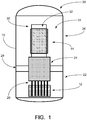
- FIGURE 1 an illustrative nuclear reactor vessel of the pressurized water reactor (PWR) type is diagrammatically depicted.
- An illustrated primary vessel 10 contains a reactor core 12, internal helical steam generators 14, and internal control rods 20.
- the illustrative reactor vessel includes four major components, namely: 1) a lower vessel 22, 2) upper internals 24, 3) an upper vessel 26 and 4) an upper vessel head 28.
- a mid-flange 29 is disposed between the lower and upper vessel sections 22, 26.
- Other vessel configurations are also contemplated.
- FIGURE 1 is diagrammatic and does not include details such as pressure vessel penetrations for flow of secondary coolant into and out of the steam generators, electrical penetrations for electrical components, and so forth.
- the lower vessel 22 of the illustrative reactor vessel 10 of FIGURE 1 contains the reactor core 12, which can have substantially any suitable configuration.
- One suitable configuration includes a stainless steel core former structure that contains the fuel assemblies and is replaceable in order to refuel the reactor, and which is supported by the lower vessel.
- the illustrative upper vessel 26 houses the steam generators 14 for this illustrative PWR which has an internal steam generator design (sometimes referred to as an integral PWR design).
- the steam generator 14 is diagrammatically shown.
- a cylindrical inner shell or upper flow shroud 30 separates a central riser region 32 from an annular down-comer region 34 in which the helical steam generators 14 are located.
- the illustrative steam generator 14 is a helical coil design, although other designs are contemplated.
- Primary reactor coolant flows across the outside of tubes of the steam generator 14 and secondary coolant flows inside the tubes of the steam generator 14.
- the primary coolant is heated by the reactor core 12 and rises through the central riser region 32 to exit the top of the shroud 30 whereupon the primary coolant flows back down via the down-comer region 34 and across the steam generators 14.
- Such primary coolant flow may be driven by natural convection, by internal or external primary coolant pumps (not illustrated), or by a combination of pump-assisted natural convection.
- the reactor vessel may have an external steam generator (not illustrated), in which case pressure vessel penetrations allow for transfer of primary coolant to and from the external steam generator.
- the illustrative upper vessel head 28 is a separate component. It is also contemplated for the vessel head to be integral with the upper vessel 26, in which case the steam generator 14 and upper shroud 30 are optionally supported by lugs on the inside of the vessel head.
- the illustrative example is an integral PWR in that it includes the internal steam generators 14, which in general may have various geometric configurations such as helical, vertical, slanted, or so forth. For the purpose of redundancy, it is generally advantageous to have more than one steam generator, whose pipes or tubes are typically interleaved within the downcomer region 34 to facilitate thermal uniformity; however, it is contemplated to include only a single steam generator.
- the illustrative steam generators 14 are shown disposed or wrapped proximate to the shroud 30, in general the steam generators may fill a substantial volume of the down-comer region 34, and in some examples the steam generators may substantially fill the annular volume between the outer surface of the shroud 30 and the inside surface of the pressure vessel 10.
- the internal steam generators or portions thereof may be disposed in whole or in part in the riser region 32, above the shroud 30, or elsewhere within the pressure vessel 10.
- the PWR may not be an integral PWR, that is, in some examples the illustrated internal steam generators may be omitted in favor of one or more external steam generators.
- the illustrative PWR is an example, and in other examples a boiling water reactor (BWR) or other reactor design may be employed, with either internal or external steam generators.
- BWR boiling water reactor
- the upper internals section 24 in greater detail.
- the upper internals section 24 provides support for control rod drives or drive mechanisms 40, 42 and control rod guide frames 44 and is also the structure through which control rod drive power and control instrumentation signals pass. This allows the upper vessel 26 and integral steam generator 14 to be removed independently of the control rod drives and associated structure.
- a more integrated design is also contemplated, such as using a common section for both the CRDM support and the integral steam generator support.
- the upper internals structure 24 includes an upper internals basket 46, a CRDM support structure 48, control rod guide frames 44, and the control rod drive mechanisms 40, 42 themselves.
- the upper internals basket 46 is suitably a welded structure that includes the mid-flange 29 and the support structure for the control rod guide frames 44.
- the control rod guide frames 44 are separate 304L stainless steel welded structures that are bolted in place
- the mid-flange 29 is a SA508 Gr 4N Cl 2 carbon steel forging
- the balance of the structure is 304L stainless steel.
- the CRDM support structure 48 includes support lattices for the control rod drives 40, 42 and guide structure for the in-core instruments. All of these are suitably 304L stainless steel.
- the CRDM support structure 48 is bolted to the upper internals basket 46.
- the illustrative example of FIGURE 2 employs two types of control rod drives 40, 42: a hydraulic control rod drive type 42 that operates the shutdown rods which are either fully withdrawn or fully inserted into the core; and an electrical control rod drive type 40 that operates the gray rods which are inserted various amounts throughout the life of the core to control the nuclear reaction rate during normal reactor operation.
- the gray rods are also configured to scram, that is, to be rapidly inserted into the reactor core 12, during certain emergency conditions. In other examples, it is contemplated to omit the shutdown rods entirely in which case the gray rods also provide shutdown operation.
- FIGURES 3-5 aspects of the shutdown rods are illustrated.
- the shutdown rods are suitably arranged in clusters mounted on spiders or the like that are all operated in single bank and are all moved by a single shutdown rod drive 42.
- FIGURES 3-5 show only the single shutdown rod drive 42, but not the spiders and individual shutdown rods. This configuration is cognizant of the fact that the shutdown rods are used in a binary "on/off" manner, and are either all wholly inserted into the reactor core 12 in order to shut down the reaction, or are all wholly withdrawn from the reactor core 12 in order to allow normal reactor operation.
- the shutdown rod drive 42 includes a cylinder housing 50, a cylinder cap 52, a cylinder base plate 54, and a connecting rod 56 providing connection to the shutdown rod lattice (not shown).
- FIGURE 4 a sectional view of the piston region with the rod in the withdrawn position is shown.
- a vent port 60 of the cylinder cap 52 is shown, together with a lift piston 62, piston rings 64 (which in some examples are metallic), a scram buffer 66, and a buffer cocking spring 68.
- the withdrawn position shown in FIGURE 4 corresponds to the shutdown control drive cylinder 42 being pressurized.
- FIGURE 5 a sectional view of the piston region with the rod in the inserted position is shown.
- An enlarged portion of FIGURE 5 shows the lift piston 62, the piston rings 64, the scram buffer or scram buffer piston 66, a rod guide bushing 70, and rod sealing rings 72 (which in some examples are metallic).
- the cylinder base plate 54 is seen in the enlarged portion to include a pressure port or inlet port 74.
- the inserted position shown in FIGURE 5 corresponds to the shutdown control drive cylinder 42 being unpressurized.
- the coolant is allowed to bleed past the piston and shaft seals 64, 72 and becomes part of the inventory returned to the reactor vessel 10.
- the shutdown rod drive cylinder 42 is mounted above the reactor core 12.
- a hydraulic line (not shown) to actuate the cylinder 42 is routed through the flange 29 and instrument lines are routed through pressure tight conduit to common connectors that are also optionally used for the gray rod drives 40.
- the extension rods that connect the control rod spiders to the shutdown rod lattice are optionally designed so that they will slide through the lattice so that a single stuck cluster will not prevent the other sets of control rods from dropping. Additionally, the extension rods are designed to be disengaged from the control rod spider so that the shutdown rods remain in the core when the upper internals 24 are removed. Disengagement and reengagement is done using remote tooling at during refueling operations.
- the shutdown rods are suspended completely out of the reactor core (that is, in the withdrawn position) by pressurization of the shutdown rod hydraulic cylinder 42.
- coolant inventory clean-up return fluid from the high pressure injection pumps is supplied at 500°F (260 °C) and 1600 psi to the underside of the lift cylinder piston 62, via the inlet port 74 of the cylinder base 54.
- the fluid present in the cylinder 50 above the piston 62 is supplied from the reactor vessel 10 through the cylinder cap vent port 60, and is therefore at the reactor vessel conditions of 600 °F (315 °C) and 1500 psi, resulting in a net 100 psi pressure differential across the piston 62.
- Piston sizing is selected such that the developed pressure differential is sufficient to support the specified load of the shutdown rods and supporting spiders and other associated components and lift the shutdown rod bank through the cylinder stroke to the top stop of the piston 62.
- the shutdown rod bank is abruptly released by ceasing the supply of pressurized coolant to the bottom side of the lift piston 62 and venting the supply line to atmospheric pressure.
- the vessel pressure at the top surface of the lift piston 62 is expected to create an initial 1500 psig pressure differential across the lift piston, which acts along with the influence of gravity to propel the translating assembly (including the lift piston 62, scram buffer piston 66, cocking spring 68, connecting rod 56, and shutdown rod lattice (not shown) downward toward the full insertion position illustrated in FIGURE 5 .
- the force of the buffer cocking spring 68 holds the buffer piston 66 out of the bore of the lift piston 62, preserving a fluid-filled buffer cavity between the two pistons 62, 66.
- the bottom surface of the buffer piston 66 impacts the fixed base plate 54 of the cylinder assembly, the continued travel of the lift piston 62 expels the trapped fluid through controlled flow restrictions, thereby dissipating the kinetic energy of the translating assembly. Additionally, kinetic energy is dissipated through elastic deformation of the translating assembly components, especially the long, relatively slender, connecting rod 56. Other kinetic energy dissipation mechanisms are also contemplated.
- the lift piston 62 impacts the buffer piston 66, bringing the translating assembly to rest.
- gray rods 80 are arranged as gray rod clusters, which in turn are yoked together in groups of two or four and supported by connecting rods 82 as shown in FIGURE 6 .
- the configuration Type 1 also includes a counterweight 84 in place of one connecting rod/cluster unit. More particularly, a yoke 86 connects two connecting rods 82 and the counterweight 84 to form a configuration of Type 1.
- a yoke 88 connects three connecting rods 84 to form a configuration of Type 2.
- the gray rod drives 40 are mounted above the reactor core 12.
- FIGURE 7 shows a plan view of the locations of the gray rod drives 40 and of the shutdown rods lift cylinder 50, respective to the CRDM support structure 48.
- the shutdown rods lift cylinder 50 is centrally located.
- Four outboard gray rod drives 40 each moving two rod configurations of Type 1 including yokes 86, move simultaneously.
- Two inboard drives 40 each moving four rod configurations of Type 2 including yokes 88, move simultaneously.
- These different sets of drives 40 optionally move together or independently. Power and signal connections are suitably routed through a pressure tight conduit or in-core instrumentation guide 90 to connectors on the mid-flange 29 (not shown in FIGURE 7 ).
- the extension rods that connect the control rod spiders to the rod lattice are optionally designed so that they will slide through the lattice so that a single stuck cluster will not prevent the other sets of control rods from dropping. Additionally, the extension rods are optionally designed to be disengaged from the control rod spider so that the gray rods can remain in the core when the upper internals are removed or be removed while the upper internals are on their support stand.
- Two suitable design styles for the gray rod control mechanism include the "magnetic jack" type and the "power screw” type. Of these, the power screw type is expected to provide more precise position control for the gray rod clusters, and accordingly the illustrated example employs the power screw type control mechanism.
- FIGURE 8 shows both the fully inserted state (left-side drawing) and fully withdrawn state (right-side drawing).
- the drawings of FIGURE 8 show the yoke 88 of the Type 2 configuration; for the Type 1 arrangement the yoke 88 is replaced by the yoke 86.
- a bottom stop/buffer assembly 100 is mounted on a reactor support 101, optionally with additional lateral support provided for the electromagnet coil assembly.
- Lower and upper support tubes 102, 104 which mount to the top of the bottom stop 100, provide the guidance for the lead screw/torque taker assembly.
- a ball nut/motor assembly 106 mounts on top of the upper support tube 104 and an electromagnet coil assembly 108 mounts to the top of the motor.
- an electromagnet coil assembly 108 mounts to the top of the motor.
- a lifting rod-to-lead screw latching assembly 110 that (when latched) supports a lifting/connection rod assembly 112 (seen extended in the inserted state, i.e. left-side drawing).
- a position indicator assembly is mounted to the support tubes 102, 104 between the ball nut/motor assembly 106 and the bottom stop assembly 100.
- the position indicator is a string potentiometer suitably mounted below the latching assembly 110, although other mounting locations are contemplated.
- the illustrated string potentiometer includes a tensioned spool 120 mounted on the support tube 102 and a "string" or cable or the like 122 having an end attached to the lifting/connection rod assembly 112 such that the string or cable 122 is drawn off the spool 120 against the tension as the lifting/connection rod assembly 112 (and, hence the attached gray rod clusters) move toward the reactor core 12 (not shown in FIGURE 8 ).
- a rotational sensor 124 measures the rotation of the tensioned spool 120 using an encoder that counts passage of fiducial markers or another rotational metric.
- the mounting of the string potentiometer can be otherwise than that illustrated, so long as the tensioned spool 120 is mounted at a location that does not move with the gray rods and the string or cable 122 is secured to move with the gray rods. It is also contemplated to integrate the rotational sensor 124 with the tensioned spool 120.
- the string potentiometer provides an electrical output signal consistent with the location of the connecting rod or other component 112 that moves with the gray control rod, thus providing positional information for the gray control rods within the reactor core 12.
- the electrical position indication signal is conveyed out of the reactor vessel 10 through an electrical feedthrough (not shown), which can be made small and/or integrated with other electrical feedthroughs.
- the position indicator device is configured and calibrated for operation at reactor vessel temperature and radiation level.
- the translating assembly of the gray rod CRDM 40 includes three elements: a lead screw/torque taker assembly; a lifting rod/connecting rod assembly; and a latching system that operatively connects the lifting rod with the lead screw.
- FIGURE 9 shows the lead screw/torque taker assembly in perspective (left side) and sectional (right side) views.
- a motor assembly includes a stator housing 130 housing a stator 132 and a rotor 134.
- An upper stator end plate 136 and a radial bearing 138 with adjustable spacer 140 complete an upper portion of the motor assembly, while a lower housing 142 and a thrust bearing 144 complete a lower portion of the motor assembly.
- FIGURE 9 further shows portions of the lifting rod 112 and the upper support tube 104.
- the latching system is illustrated, including the lifting rod-to-lead screw latching assembly 110 and a portion of the electromagnet coil assembly 108. Also shown in FIGURE 10 are an end 111 of the lifting rod 112 and a proximate end of the lead screw 160 terminating at or in the latching assembly 110. Latches 170 directly connect the top end 111 of the lifting rod 112 to the lead screw 160 for normal operation, and disconnect the lifting rod 112 during scram (see FIGURE 11 ). The bottom of the lifting rod 112 is threaded to the top of the connecting rod 82 (optionally by the intermediary yoke 86 or intermediary yoke 88 ) thereby creating a continuous lifting rod/connecting rod assembly.
- FIGURE 10 also shows a portion of the motor including portions of the motor housing 130, stator 132, and rotor 134, which is shown in full in FIGURE 9 .
- the latches 170 are housed in a latch housing 172 that includes a spring guide for a latch spring 174. Additional components of the illustrated latching system embodiment include an electromagnet housing 176 housing electromagnets 177 forming an electromagnet coil stack, and permanent magnets 178 on the latches 170.
- the lead screw 160 is threaded into a latching system base 179 of the latch housing 172.
- the latches 170 are arranged to pivot about pivot locations 180 to provide a failsafe scram due to downward rod load.
- the lead screw 160 is continuously supported by a ball nut motor assembly (best seen in FIGURE 9 ) which allows for very fine control of lead screw position and consequently very fine control of the position of the control rod assembly.
- the motor e.g., stator 132, rotor 134
- stator 132, rotor 134 is a synchronous motor in which the rotor 134 is a permanent magnet. This design has advantages such as compactness and simplicity; however, other motor configurations are also contemplated.
- the lead screw 160 does not scram. Instead, during a scram the top end of the lifting rod 112 of the lifting rod/connection rod assembly is disconnected from the lead screw 160 by the magnetically activated latching system (see FIGURE 11 ). When power is cut to the electromagnets 177 the failsafe latching system releases the lifting/connection rod assembly (and thus the control rod assembly) from the lead screw 160 thereby initiating a scram.
- a bottom stop and buffering system (not illustrated, but suitably similar to the bottom stop and buffering system of the illustrative shutdown rods described herein with reference to FIGURES 4 and 5 ) is incorporated into the base/buffer assembly to dissipate the kinetic energy at the end of the scram stroke and to set the rod bottom elevation.
- a torque taker (not shown) is attached to the lead screw 160 to react the motor torque thereby providing translation of the lead screw/control rod assembly.
- FIGURE 9 illustrates the ball nut motor assembly
- FIGURE 10 shows the latching system engaged for normal operation.
- the permanent magnets 178 on the latches 170 are magnetically attracted toward the powered electromagnets 177 thus pivoting the latches 170 about the pivot locations 180 and engaging the latches 170 with a mating region of the lifting rod 112.
- the latches 170 are secured with the lifting rod 112 in the normal state shown in FIGURE 10 .
- the latching system base 179 is threaded to or otherwise secured with the lead screw 160. Accordingly, in the normal state of FIGURE 10 the lifting rod 112 is secured with the lead screw 160 via the latching system, and so as the ball nut motor assembly shown in FIGURE 9 translates the lead screw 160 the lifting rod 112 is translated with the lead screw 160.
- FIGURE 11 shows the lifting rod 112, and consequently the control rod assembly, during a scram.
- the power to the electromagnets 177 is cut, that is, turned off. This removes the attractive force on the permanent magnets 178 on the latches 170, and the latch spring 174 extends to pivot the latches 170 about the pivot locations 180 and away from the mating region of the lifting rod 112. This disengages the latches 170 from the lifting rod 112, and the lifting/connection rod assembly (and thus the control rod assembly) falls toward the reactor 12.
- the lead screw 160 is seen in FIGURE 11 still at the previous withdrawal height (that is, the lead screw 160 is not scrammed), but power to the electromagnet coils 177 has been cut so that the magnetic field from the coils is removed.
- the lead screw 160 is driven to the fully inserted position via the ball nut motor (see again FIGURE 9 ).
- a lead screw on-bottom sensor is used to confirm lead screw full insertion.
- an angled camming surface 182 on the top 111 of the lifting rod 112, which is scrammed to the bottom, will cam the latches 170 to their near full out position.
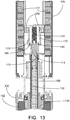
- FIGURE 13 shows the latches 170 being fully re-engage with the mating region of the lifting rod 112 so that the lifting/connection rod assembly is once again connected to the lead screw 160. Normal operation can then resume as per FIGURE 10 .
- FIGURE 12 shows the lead screw 160 being driven back down to the fully inserted position in preparation for re-engagement of the lifting rod 112. Power to the electromagnet coils 177 is still cut and the latches 160 are still disengaged. The angled camming surfaces 182 on the top 111 of the lifting rod 112 are camming the latches 170 back into partial engagement with the top 111 of the lifting rod 112.
- FIGURE 13 shows the lead screw 160 still on bottom but with the power restored to the electromagnet coils 177. The restored magnet field has now re-engaged the latches 170 with the mating region of the lifting rod 112.
- FIGURE 9 diagrammatically shows a suitable example of the ball nut/motor assembly 106, including lower and upper ball nut assemblies 150, 152.
- substantially any type of motor can be used, suitably configured for operation in the pressure vessel environment.
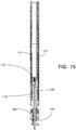
- FIGURES 14 and 15 an illustrative example is shown which employs a brushless DC electronically controlled (BLDC) motor 184 with lower ball nut assembly 185.
- the assembly 184, 185 is an illustrative embodiment of the ball nut/motor assembly 106.
- the illustrative BLDC motor 184 includes a wound stator core assembly 186 disposed between a stator outer shell 187 and a stator inner shell 188 and secured by a stator upper housing 189 and stator lower housing 190.
- a permanent magnet rotor 191 includes permanent magnets 192.
- the BLDC motor 184 produces torque from interaction of magnetic flux of the rotor magnets 192 and the current carrying stator conductors of the stator core assembly 186.
- the lower ball nut assembly 185 is analogous to the lower ball-nut assembly 150 of FIGURE 9 ; however, in the illustrative assembly of FIGURE 14 there is no upper ball-nut assembly corresponding to the upper ball nut assembly 152 of FIGURE 9 .
- the assembly of FIGURE 14 also includes a radial bearing 193, a thrust bearing 194 secured by a thrust bearing lock nut 195, and a motor top cap 196.
- An insulated and environmentally robust electrical connection to the motor is provided by a lead wire gland 197.
- BLDC motor 184 and lower ball-nut assembly 185 are illustrated in the context of the control rod drive mechanism (CRDM) of FIGURES 10-13 .
- the illustrative CRDM of FIGURE 15 also includes the previously described electromagnet coil stack assembly 177, lifting rod-to-lead screw latching assembly 110, lead screw 160, and lifting rod 112.
- the ball-nut assembly 185 engages the lead screw 160 so that, as the motor 184 rotates the permanent magnet rotor 191 and the secured ball-nut assembly 185, the lead screw 160 is driven linearly.
- the middle section includes the internals support flange or "mid-flange" 29.
- This section can be made relatively thin, and provides support for the control rod drive mechanism and guides for the in-core instrumentation.
- This section provides electrical and hydraulic inputs for the control rod drive mechanisms (CRDMs).
- a reactor coolant drain penetration (not illustrated) is optionally also incorporated in this section. This drain line, if incorporated, is optionally isolated by an internal valve whenever the reactor is pressurized to limit or eliminate its potential as a loss of coolant accident (LOCA) site.
- LOCA loss of coolant accident
- the illustrated upper internals 24 including the CRDM do not include illustrated thermal insulation. However, it is contemplated to insulate these components using an insulation system capable of withstanding a design temperature of at least about 650 °F (343 °C). By using the insulation system, external cooling water will not be required although may optionally also be used. For example, cooling water can be supplied to the electrical devices to reduce the severity of the heat duty imposed by the operating environment.
- the insulation system facilitates locating the electrical CRDM within the pressure vessel, which reduces the overall height of the reactor vessel 10, significantly reduces the number of penetrations into the reactor vessel 10, and enables a complete reactor module to be shipped as a single unit. Another advantage is reduction of the overall height of the containment structure (not shown). Although the use of insulation is believed to be advantageous, other contemplated solutions include the use of water cooling and/or selecting materials capable of withstanding the high operating temperature without insulation.
- the illustrative reactor is an integral pressurized water reactor (PWR) configuration.
- PWR pressurized water reactor
- BWRs boiling water reactors
Landscapes
- Physics & Mathematics (AREA)
- Engineering & Computer Science (AREA)
- Plasma & Fusion (AREA)
- General Engineering & Computer Science (AREA)
- High Energy & Nuclear Physics (AREA)
- Chemical & Material Sciences (AREA)
- Chemical Kinetics & Catalysis (AREA)
- Monitoring And Testing Of Nuclear Reactors (AREA)
Description
- This application claims the benefit of
U.S. Provisional Application No. 61/185,887 filed June 10, 2009 - In a pressurized water reactor (PWR) or other type of nuclear reactor, movable control rods are used to control the nuclear reaction. The control rods include a neutron absorbing material, and are arranged to be inserted into the reactor core. In general, the further the control rods are inserted into the core, the more neutrons are absorbed and the more the nuclear reaction rate is slowed. Precise control of the amount of insertion, and accurate measurement of same, is useful in order to precisely control the reactivity. The control rods drive mechanism (CRDM) provides this control.
- In an emergency, the control rods can be fully inserted in order to quickly quench the nuclear reaction. In such a "scram", it is useful to have an alternative fast mechanism for inserting the control rods. Additionally or alternatively, it is known to have dedicated control rods that are either fully inserted (thus turning the nuclear reaction "off") or fully withdrawn (thus making the reactor operational). In such systems, the "on/off" rods are sometimes referred to as "shutdown rods" while the continuously adjustable control rods are sometimes referred to as "gray rods".
- Given these considerations, it is known to construct a CRDM employing a lead screw that is engaged by a separable roller-nut assembly. During normal operation, the roller-nut assembly is clamped onto the lead screw by an affirmative magnetic force acting against biasing springs. By turning the roller nut the lead screw, and hence the attached control rods, are moved in precisely controllable fashion toward or away from the reactor core. In a scram, the electrical current is cut thus cutting the magnetic force, the biasing springs open the separable roller nut, and the gray rod including the lead screw scrams. An example of such a configuration is disclosed, for example, in Domingo Ricardo Giorsetti, "Analysis of the Technological Differences Between Stationary & Maritime Nuclear Power Plants", M.S.N.E. Thesis, Massachusetts Institute of Technology (MIT) Department of Nuclear Engineering (1977).
- For an integral pressurized water reactor (integral PWR), it is known to mount the CRDM externally and to couple with the control rods inside the pressure vessel by suitable feedthroughs. To reduce the extent of feedthroughs, it has also been proposed to integrate the CRDM within the pressure vessel. See, for example, Ishizaka et al., "Development of a Built-In Type Control Rod Drive Mechanism (CRDM) For Advanced Marine Reactor X (MRX)", Proceedings of the International Conference on Design and Safety of Advanced Nuclear Power Reactors (ANP '92), October 25-29, 1992 (Tokyo Japan) published by the Atomic Energy Society of Japan in October 1992.
- Control rod drive mechanisms with magnetic coupling are known e.g. from
JP 2003 270375 A US 3 734 825 A , andUS 3 741 867 A .GB 927 522 - Existing CRDM designs have certain disadvantages. These disadvantages are enhanced when an internal CRDM design is chosen in which the complex electro-mechanical CDRM is internal to the high pressure and high temperature environment within the pressure vessel. Placement of the CRDM internally within the pressure vessel also imposes difficult structural challenges.
- The separable roller-nut creates a complex linkage with the lead screw that can adversely impact gray rod insertion precision during normal operation. Reattachment of the roller-nut to the lead screw can be complex, and it may not be immediately apparent when contact is reestablished, thus introducing a positional offset after recovery from the scram event. Scramming the lead screw also has the potential to cause irrecoverable damage to the threading or structural integrity of the lead screw. Still further, wear over time can be a problem for the complex separable roller-nut.
- Another consideration is reliability. Because rod scramming is a safety-critical feature, it must operate reliably, even in a loss of coolant accident (LOCA) or other failure mode that may include interruption of electrical power, large pressure changes, or so forth.
- The control rod position detector is also typically a complex device. In some systems, an external position detector is employed, which requires feedthroughs across the pressure vessel wall. For the internal CRDM of the MRX reactor, a complex position detector was designed in which a transducer generates a torsional strain pulse that passes through a magnetoresistive waveguide, and magnetic field interactions are measured to adduce the rod position. In general, an internal position detector operating on an electrical resistance basis is prone to error due to temperature-induced changes in material resistivity.
- The scope of the invention is defined by the subject-matter of the appended claims.
- In one aspect of the disclosure, a control rod mechanism for use in a nuclear reactor, the control rod mechanism comprises: a control rod configured for insertion in a reactor core to absorb neutrons; a connecting rod connected with the control rod; a drive mechanism including a lead screw engaged with a motor-driven nut such that rotating the nut causes linear translation of the lead screw; and a latch operatively connecting the connecting rod to move together with the lead screw, the latch opening responsive to a loss or removal of electrical power to detach the connecting rod from the lead screw.
- In another aspect of the disclosure, a control rod control method comprises moving a control rod linearly using a lead screw and, responsive to a scram, detaching the control rod from the lead screw whereby the control rod scrams but the lead screw does not scram.
- In another aspect of the disclosure, a nuclear reactor comprises: a reactor core; a pressure vessel including a lower vessel section containing the reactor core, an upper vessel section disposed above the reactor core and above the lower vessel section, and a mid-flange located above a reactor core and disposed between the lower vessel section and the upper vessel section; and an internal control rod drive mechanism (CRDM) supported by the mid flange.
- In another aspect of the disclosure, a control rod drive mechanism (CRDM) for use in a nuclear reactor comprises: a connecting rod connected with at least one control rod; a lead screw; a drive mechanism configured to linearly translate the lead screw; an electromagnet coil assembly; and a latching assembly that latches the connecting rod to the lead screw responsive to energizing the electromagnet coil assembly and unlatches the connecting rod from the lead screw responsive to deenergizing the electromagnet coil assembly.
- The invention may take form in various components and arrangements of components, and in various process operations and arrangements of process operations. The drawings are only for purposes of illustrating examples and preferred embodiments and are not to be construed as limiting the invention.
-
FIGURE 1 diagrammatically shows an illustrative nuclear reactor vessel of the pressurized water reactor (PWR) type. -
FIGURE 2 diagrammatically shows the upper internals section of the illustrative nuclear reactor vessel ofFIGURE 1 . -
FIGURES 3-5 diagrammatically show aspects of a shutdown control rod system employing hydraulic lift. -
FIGURES 6-15 diagrammatically show aspects of a control rod system with electromagnetic gray rod functionality and a magnetic latch system for scram functionality. - With reference to
FIGURE 1 , an illustrative nuclear reactor vessel of the pressurized water reactor (PWR) type is diagrammatically depicted. An illustratedprimary vessel 10 contains areactor core 12, internalhelical steam generators 14, andinternal control rods 20. The illustrative reactor vessel includes four major components, namely: 1) alower vessel 22, 2)upper internals 24, 3) anupper vessel 26 and 4) anupper vessel head 28. A mid-flange 29 is disposed between the lower andupper vessel sections FIGURE 1 is diagrammatic and does not include details such as pressure vessel penetrations for flow of secondary coolant into and out of the steam generators, electrical penetrations for electrical components, and so forth. - The
lower vessel 22 of theillustrative reactor vessel 10 ofFIGURE 1 contains thereactor core 12, which can have substantially any suitable configuration. One suitable configuration includes a stainless steel core former structure that contains the fuel assemblies and is replaceable in order to refuel the reactor, and which is supported by the lower vessel. The illustrativeupper vessel 26 houses thesteam generators 14 for this illustrative PWR which has an internal steam generator design (sometimes referred to as an integral PWR design). InFIGURE 1 , thesteam generator 14 is diagrammatically shown. A cylindrical inner shell orupper flow shroud 30 separates acentral riser region 32 from an annular down-comer region 34 in which thehelical steam generators 14 are located. Theillustrative steam generator 14 is a helical coil design, although other designs are contemplated. Primary reactor coolant flows across the outside of tubes of thesteam generator 14 and secondary coolant flows inside the tubes of thesteam generator 14. In a typical circulation pattern the primary coolant is heated by thereactor core 12 and rises through thecentral riser region 32 to exit the top of theshroud 30 whereupon the primary coolant flows back down via the down-comer region 34 and across thesteam generators 14. Such primary coolant flow may be driven by natural convection, by internal or external primary coolant pumps (not illustrated), or by a combination of pump-assisted natural convection. Although an integral PWR design is illustrated, it is also contemplated for the reactor vessel to have an external steam generator (not illustrated), in which case pressure vessel penetrations allow for transfer of primary coolant to and from the external steam generator. The illustrativeupper vessel head 28 is a separate component. It is also contemplated for the vessel head to be integral with theupper vessel 26, in which case thesteam generator 14 andupper shroud 30 are optionally supported by lugs on the inside of the vessel head. - The illustrative example is an integral PWR in that it includes the
internal steam generators 14, which in general may have various geometric configurations such as helical, vertical, slanted, or so forth. For the purpose of redundancy, it is generally advantageous to have more than one steam generator, whose pipes or tubes are typically interleaved within thedowncomer region 34 to facilitate thermal uniformity; however, it is contemplated to include only a single steam generator. Although theillustrative steam generators 14 are shown disposed or wrapped proximate to theshroud 30, in general the steam generators may fill a substantial volume of the down-comer region 34, and in some examples the steam generators may substantially fill the annular volume between the outer surface of theshroud 30 and the inside surface of thepressure vessel 10. It is also contemplated for the internal steam generators or portions thereof to be disposed in whole or in part in theriser region 32, above theshroud 30, or elsewhere within thepressure vessel 10. On the other hand, in some examples the PWR may not be an integral PWR, that is, in some examples the illustrated internal steam generators may be omitted in favor of one or more external steam generators. Still further, the illustrative PWR is an example, and in other examples a boiling water reactor (BWR) or other reactor design may be employed, with either internal or external steam generators. - With reference to
FIGURE 2 , theupper internals section 24 in greater detail. In the illustrative design theupper internals section 24 provides support for control rod drives or drivemechanisms upper vessel 26 andintegral steam generator 14 to be removed independently of the control rod drives and associated structure. However, a more integrated design is also contemplated, such as using a common section for both the CRDM support and the integral steam generator support. - With particular reference to the illustrative example of
FIGURE 2 , theupper internals structure 24 includes anupper internals basket 46, aCRDM support structure 48, control rod guide frames 44, and the controlrod drive mechanisms upper internals basket 46 is suitably a welded structure that includes the mid-flange 29 and the support structure for the control rod guide frames 44. In one suitable example, the control rod guide frames 44 are separate 304L stainless steel welded structures that are bolted in place, the mid-flange 29 is a SA508 Gr 4N Cl 2 carbon steel forging, and the balance of the structure is 304L stainless steel. TheCRDM support structure 48 includes support lattices for the control rod drives 40, 42 and guide structure for the in-core instruments. All of these are suitably 304L stainless steel. TheCRDM support structure 48 is bolted to theupper internals basket 46. These are merely illustrative materials and construction, and other configurations and/or reactor-compatible materials are also contemplated. - The illustrative example of
FIGURE 2 employs two types of control rod drives 40, 42: a hydraulic controlrod drive type 42 that operates the shutdown rods which are either fully withdrawn or fully inserted into the core; and an electrical controlrod drive type 40 that operates the gray rods which are inserted various amounts throughout the life of the core to control the nuclear reaction rate during normal reactor operation. The gray rods are also configured to scram, that is, to be rapidly inserted into thereactor core 12, during certain emergency conditions. In other examples, it is contemplated to omit the shutdown rods entirely in which case the gray rods also provide shutdown operation. - With continuing reference to
FIGURE 2 and with further reference toFIGURES 3-5 , aspects of the shutdown rods are illustrated. The shutdown rods are suitably arranged in clusters mounted on spiders or the like that are all operated in single bank and are all moved by a singleshutdown rod drive 42.FIGURES 3-5 show only the singleshutdown rod drive 42, but not the spiders and individual shutdown rods. This configuration is cognizant of the fact that the shutdown rods are used in a binary "on/off" manner, and are either all wholly inserted into thereactor core 12 in order to shut down the reaction, or are all wholly withdrawn from thereactor core 12 in order to allow normal reactor operation. - With particular reference to
FIGURE 3 , theshutdown rod drive 42 includes acylinder housing 50, acylinder cap 52, acylinder base plate 54, and a connectingrod 56 providing connection to the shutdown rod lattice (not shown). The illustrative shutdown rod drive 42 ofFIGURES 3-5 is a hydraulically actuated drive using reactor coolant inventory clean-up return fluid from high pressure injection pumps at approximately 500 °F (260 °C) and 1600 psi (1 psi = 6.9 kPa) to hold the shutdown rod bank out of thereactor core 12. - With particular reference to
FIGURE 4 , a sectional view of the piston region with the rod in the withdrawn position is shown. In an enlarged portion ofFIGURE 4 avent port 60 of thecylinder cap 52 is shown, together with alift piston 62, piston rings 64 (which in some examples are metallic), ascram buffer 66, and abuffer cocking spring 68. The withdrawn position shown inFIGURE 4 corresponds to the shutdowncontrol drive cylinder 42 being pressurized. - With particular reference to
FIGURE 5 , a sectional view of the piston region with the rod in the inserted position is shown. An enlarged portion ofFIGURE 5 shows thelift piston 62, the piston rings 64, the scram buffer or scrambuffer piston 66, arod guide bushing 70, and rod sealing rings 72 (which in some examples are metallic). Thecylinder base plate 54 is seen in the enlarged portion to include a pressure port orinlet port 74. The inserted position shown inFIGURE 5 corresponds to the shutdowncontrol drive cylinder 42 being unpressurized. - In some examples, the coolant is allowed to bleed past the piston and shaft seals 64, 72 and becomes part of the inventory returned to the
reactor vessel 10. The shutdownrod drive cylinder 42 is mounted above thereactor core 12. A hydraulic line (not shown) to actuate thecylinder 42 is routed through theflange 29 and instrument lines are routed through pressure tight conduit to common connectors that are also optionally used for the gray rod drives 40. The extension rods that connect the control rod spiders to the shutdown rod lattice are optionally designed so that they will slide through the lattice so that a single stuck cluster will not prevent the other sets of control rods from dropping. Additionally, the extension rods are designed to be disengaged from the control rod spider so that the shutdown rods remain in the core when theupper internals 24 are removed. Disengagement and reengagement is done using remote tooling at during refueling operations. - During normal reactor operation, the shutdown rods are suspended completely out of the reactor core (that is, in the withdrawn position) by pressurization of the shutdown rod
hydraulic cylinder 42. For example, in one suitable example coolant inventory clean-up return fluid from the high pressure injection pumps is supplied at 500°F (260 °C) and 1600 psi to the underside of thelift cylinder piston 62, via theinlet port 74 of thecylinder base 54. In this example, the fluid present in thecylinder 50 above thepiston 62 is supplied from thereactor vessel 10 through the cylindercap vent port 60, and is therefore at the reactor vessel conditions of 600 °F (315 °C) and 1500 psi, resulting in a net 100 psi pressure differential across thepiston 62. Piston sizing is selected such that the developed pressure differential is sufficient to support the specified load of the shutdown rods and supporting spiders and other associated components and lift the shutdown rod bank through the cylinder stroke to the top stop of thepiston 62. - In the event of a vessel-pressurized scram, the shutdown rod bank is abruptly released by ceasing the supply of pressurized coolant to the bottom side of the
lift piston 62 and venting the supply line to atmospheric pressure. In the aforementioned example the vessel pressure at the top surface of thelift piston 62 is expected to create an initial 1500 psig pressure differential across the lift piston, which acts along with the influence of gravity to propel the translating assembly (including thelift piston 62,scram buffer piston 66, cockingspring 68, connectingrod 56, and shutdown rod lattice (not shown) downward toward the full insertion position illustrated inFIGURE 5 . During the descent of the translating assembly, the force of thebuffer cocking spring 68 holds thebuffer piston 66 out of the bore of thelift piston 62, preserving a fluid-filled buffer cavity between the twopistons buffer piston 66 impacts the fixedbase plate 54 of the cylinder assembly, the continued travel of thelift piston 62 expels the trapped fluid through controlled flow restrictions, thereby dissipating the kinetic energy of the translating assembly. Additionally, kinetic energy is dissipated through elastic deformation of the translating assembly components, especially the long, relatively slender, connectingrod 56. Other kinetic energy dissipation mechanisms are also contemplated. When the fluid is expelled from the cavity, thelift piston 62 impacts thebuffer piston 66, bringing the translating assembly to rest. - With continuing reference to
FIGURES 1 and2 and with further reference toFIGURES 6-14 , an illustrative example of the gray rods and an illustrative example of the associateddrive mechanisms 40 is described. As seen inFIGURE 6 , in the illustrative example there are two different gray rod configurations (Type 1 and Type 2). Thegray rods 80 are arranged as gray rod clusters, which in turn are yoked together in groups of two or four and supported by connectingrods 82 as shown inFIGURE 6 . The configuration Type 1 also includes acounterweight 84 in place of one connecting rod/cluster unit. More particularly, ayoke 86 connects two connectingrods 82 and thecounterweight 84 to form a configuration of Type 1. Ayoke 88 connects three connectingrods 84 to form a configuration of Type 2. The gray rod drives 40 are mounted above thereactor core 12.FIGURE 7 shows a plan view of the locations of the gray rod drives 40 and of the shutdown rods liftcylinder 50, respective to theCRDM support structure 48. The shutdown rods liftcylinder 50 is centrally located. Four outboard gray rod drives 40, each moving two rod configurations of Type 1 includingyokes 86, move simultaneously. Twoinboard drives 40, each moving four rod configurations of Type 2 includingyokes 88, move simultaneously. These different sets ofdrives 40 optionally move together or independently. Power and signal connections are suitably routed through a pressure tight conduit or in-core instrumentation guide 90 to connectors on the mid-flange 29 (not shown inFIGURE 7 ). - As with the shutdown rods, the extension rods that connect the control rod spiders to the rod lattice are optionally designed so that they will slide through the lattice so that a single stuck cluster will not prevent the other sets of control rods from dropping. Additionally, the extension rods are optionally designed to be disengaged from the control rod spider so that the gray rods can remain in the core when the upper internals are removed or be removed while the upper internals are on their support stand. Two suitable design styles for the gray rod control mechanism include the "magnetic jack" type and the "power screw" type. Of these, the power screw type is expected to provide more precise position control for the gray rod clusters, and accordingly the illustrated example employs the power screw type control mechanism.
- With reference to
FIGURE 8 , in one illustrated example the grayrod control mechanism 40 employs a ball nut lifting rod configuration.FIGURE 8 shows both the fully inserted state (left-side drawing) and fully withdrawn state (right-side drawing). The drawings ofFIGURE 8 show theyoke 88 of the Type 2 configuration; for the Type 1 arrangement theyoke 88 is replaced by theyoke 86. In the example shown inFIGURE 8 , a bottom stop/buffer assembly 100 is mounted on areactor support 101, optionally with additional lateral support provided for the electromagnet coil assembly. Lower andupper support tubes bottom stop 100, provide the guidance for the lead screw/torque taker assembly. A ball nut/motor assembly 106 mounts on top of theupper support tube 104 and anelectromagnet coil assembly 108 mounts to the top of the motor. Within theelectromagnet coil assembly 108 resides a lifting rod-to-leadscrew latching assembly 110 that (when latched) supports a lifting/connection rod assembly 112 (seen extended in the inserted state, i.e. left-side drawing). - A position indicator assembly is mounted to the
support tubes motor assembly 106 and thebottom stop assembly 100. In some examples, the position indicator is a string potentiometer suitably mounted below the latchingassembly 110, although other mounting locations are contemplated. The illustrated string potentiometer includes a tensioned spool 120 mounted on thesupport tube 102 and a "string" or cable or the like 122 having an end attached to the lifting/connection rod assembly 112 such that the string orcable 122 is drawn off the spool 120 against the tension as the lifting/connection rod assembly 112 (and, hence the attached gray rod clusters) move toward the reactor core 12 (not shown inFIGURE 8 ). When the motion is reversed, the tension in the tensioned spool 120 causes the string orcable 122 to roll back onto the spool 120. Arotational sensor 124 measures the rotation of the tensioned spool 120 using an encoder that counts passage of fiducial markers or another rotational metric. The mounting of the string potentiometer can be otherwise than that illustrated, so long as the tensioned spool 120 is mounted at a location that does not move with the gray rods and the string orcable 122 is secured to move with the gray rods. It is also contemplated to integrate therotational sensor 124 with the tensioned spool 120. The string potentiometer provides an electrical output signal consistent with the location of the connecting rod orother component 112 that moves with the gray control rod, thus providing positional information for the gray control rods within thereactor core 12. The electrical position indication signal is conveyed out of thereactor vessel 10 through an electrical feedthrough (not shown), which can be made small and/or integrated with other electrical feedthroughs. The position indicator device is configured and calibrated for operation at reactor vessel temperature and radiation level. - With continuing reference to
FIGURE 8 and with further reference toFIGURES 9-14 , in the illustrated embodiment the translating assembly of thegray rod CRDM 40 includes three elements: a lead screw/torque taker assembly; a lifting rod/connecting rod assembly; and a latching system that operatively connects the lifting rod with the lead screw.FIGURE 9 shows the lead screw/torque taker assembly in perspective (left side) and sectional (right side) views. A motor assembly includes astator housing 130 housing astator 132 and arotor 134. An upperstator end plate 136 and aradial bearing 138 withadjustable spacer 140 complete an upper portion of the motor assembly, while alower housing 142 and athrust bearing 144 complete a lower portion of the motor assembly. A lower ball-nut assembly 150 disposed within thelower housing 142 is threaded to therotor 134, and an upperball nut assembly 152 is also threaded to therotor 134. Both ball-nut assemblies FIGURE 9). FIGURE 9 further shows portions of the liftingrod 112 and theupper support tube 104. - With reference to
FIGURE 10 , the latching system is illustrated, including the lifting rod-to-leadscrew latching assembly 110 and a portion of theelectromagnet coil assembly 108. Also shown inFIGURE 10 are anend 111 of the liftingrod 112 and a proximate end of thelead screw 160 terminating at or in the latchingassembly 110.Latches 170 directly connect thetop end 111 of the liftingrod 112 to thelead screw 160 for normal operation, and disconnect the liftingrod 112 during scram (seeFIGURE 11 ). The bottom of the liftingrod 112 is threaded to the top of the connecting rod 82 (optionally by theintermediary yoke 86 or intermediary yoke 88) thereby creating a continuous lifting rod/connecting rod assembly. The bottom of the connectingrod 82 couples directly to the control rod spiders thereby attaching the control rods to the mechanism. Optionally, amagnet 113 is disposed proximate to the top 111 of the liftingrod 112 to provide a magnetic signal for a magnetically-based position indicator (see FIGURE 21).FIGURE 10 also shows a portion of the motor including portions of themotor housing 130,stator 132, androtor 134, which is shown in full inFIGURE 9 . - The
latches 170 are housed in alatch housing 172 that includes a spring guide for alatch spring 174. Additional components of the illustrated latching system embodiment include anelectromagnet housing 176housing electromagnets 177 forming an electromagnet coil stack, andpermanent magnets 178 on thelatches 170. Thelead screw 160 is threaded into alatching system base 179 of thelatch housing 172. Thelatches 170 are arranged to pivot aboutpivot locations 180 to provide a failsafe scram due to downward rod load. - In this embodiment, the
lead screw 160 is continuously supported by a ball nut motor assembly (best seen inFIGURE 9 ) which allows for very fine control of lead screw position and consequently very fine control of the position of the control rod assembly. In the illustrated embodiment, the motor (e.g.,stator 132, rotor 134) is a synchronous motor in which therotor 134 is a permanent magnet. This design has advantages such as compactness and simplicity; however, other motor configurations are also contemplated. - The
lead screw 160 does not scram. Instead, during a scram the top end of the liftingrod 112 of the lifting rod/connection rod assembly is disconnected from thelead screw 160 by the magnetically activated latching system (seeFIGURE 11 ). When power is cut to theelectromagnets 177 the failsafe latching system releases the lifting/connection rod assembly (and thus the control rod assembly) from thelead screw 160 thereby initiating a scram. A bottom stop and buffering system (not illustrated, but suitably similar to the bottom stop and buffering system of the illustrative shutdown rods described herein with reference toFIGURES 4 and5 ) is incorporated into the base/buffer assembly to dissipate the kinetic energy at the end of the scram stroke and to set the rod bottom elevation. A torque taker (not shown) is attached to thelead screw 160 to react the motor torque thereby providing translation of the lead screw/control rod assembly. - The normal state, that is, the state prior to scram, is shown in
FIGURES 9 and10 .FIGURE 9 illustrates the ball nut motor assembly andFIGURE 10 shows the latching system engaged for normal operation. As seen inFIGURE 10 , thepermanent magnets 178 on thelatches 170 are magnetically attracted toward thepowered electromagnets 177 thus pivoting thelatches 170 about thepivot locations 180 and engaging thelatches 170 with a mating region of the liftingrod 112. Thus, thelatches 170 are secured with the liftingrod 112 in the normal state shown inFIGURE 10 . Further, thelatching system base 179 is threaded to or otherwise secured with thelead screw 160. Accordingly, in the normal state ofFIGURE 10 the liftingrod 112 is secured with thelead screw 160 via the latching system, and so as the ball nut motor assembly shown inFIGURE 9 translates thelead screw 160 the liftingrod 112 is translated with thelead screw 160. - Scram is described with reference to
FIGURE 11 , which shows the liftingrod 112, and consequently the control rod assembly, during a scram. To initiate scram the power to theelectromagnets 177 is cut, that is, turned off. This removes the attractive force on thepermanent magnets 178 on thelatches 170, and thelatch spring 174 extends to pivot thelatches 170 about thepivot locations 180 and away from the mating region of the liftingrod 112. This disengages thelatches 170 from the liftingrod 112, and the lifting/connection rod assembly (and thus the control rod assembly) falls toward thereactor 12. Thelead screw 160 is seen inFIGURE 11 still at the previous withdrawal height (that is, thelead screw 160 is not scrammed), but power to the electromagnet coils 177 has been cut so that the magnetic field from the coils is removed. - As further shown in
FIGURE 11 , the pivoting of thelatches 170 about thepivot locations 180 is stopped by impingement at alocation 181 with the spring guide of thelatch housing 172. - With continuing reference to
FIGURE 11 and further reference toFIGURES 12 and13 , to re-engage the mechanism after a scram, thelead screw 160 is driven to the fully inserted position via the ball nut motor (see againFIGURE 9 ). A lead screw on-bottom sensor is used to confirm lead screw full insertion. With particular reference toFIGURE 12 , as thelead screw 160 nears the fully inserted position anangled camming surface 182 on the top 111 of the liftingrod 112, which is scrammed to the bottom, will cam thelatches 170 to their near full out position. With particular reference toFIGURE 13 , when power is restored to theelectromagnets 177, thelatches 170 will fully re-engage with the mating region of the liftingrod 112 so that the lifting/connection rod assembly is once again connected to thelead screw 160. Normal operation can then resume as perFIGURE 10 . To reiterate,FIGURE 12 shows thelead screw 160 being driven back down to the fully inserted position in preparation for re-engagement of the liftingrod 112. Power to the electromagnet coils 177 is still cut and thelatches 160 are still disengaged. The angled camming surfaces 182 on the top 111 of the liftingrod 112 are camming thelatches 170 back into partial engagement with the top 111 of the liftingrod 112.FIGURE 13 shows thelead screw 160 still on bottom but with the power restored to the electromagnet coils 177. The restored magnet field has now re-engaged thelatches 170 with the mating region of the liftingrod 112. -
FIGURE 9 diagrammatically shows a suitable example of the ball nut/motor assembly 106, including lower and upperball nut assemblies - With reference to
FIGURES 14 and15 , an illustrative example is shown which employs a brushless DC electronically controlled (BLDC) motor 184 with lowerball nut assembly 185. Theassembly motor assembly 106. With particular reference toFIGURE 14 , theillustrative BLDC motor 184 includes a woundstator core assembly 186 disposed between a statorouter shell 187 and a statorinner shell 188 and secured by a statorupper housing 189 and statorlower housing 190. Apermanent magnet rotor 191 includespermanent magnets 192. TheBLDC motor 184 produces torque from interaction of magnetic flux of therotor magnets 192 and the current carrying stator conductors of thestator core assembly 186. The lowerball nut assembly 185 is analogous to the lower ball-nut assembly 150 ofFIGURE 9 ; however, in the illustrative assembly ofFIGURE 14 there is no upper ball-nut assembly corresponding to the upperball nut assembly 152 ofFIGURE 9 . The assembly ofFIGURE 14 also includes aradial bearing 193, athrust bearing 194 secured by a thrust bearinglock nut 195, and amotor top cap 196. An insulated and environmentally robust electrical connection to the motor is provided by alead wire gland 197. For example, some suitable insulated lead wire glands are available from Conax® Technologies (Buffalo, New York, USA). With particular reference toFIGURE 15 , theBLDC motor 184 and lower ball-nut assembly 185 are illustrated in the context of the control rod drive mechanism (CRDM) ofFIGURES 10-13 . The illustrative CRDM ofFIGURE 15 also includes the previously described electromagnetcoil stack assembly 177, lifting rod-to-leadscrew latching assembly 110,lead screw 160, and liftingrod 112. The ball-nut assembly 185 engages thelead screw 160 so that, as themotor 184 rotates thepermanent magnet rotor 191 and the secured ball-nut assembly 185, thelead screw 160 is driven linearly. - With returning reference to
FIGURES 1 and2 , an advantage of the disclosed reactor design is that the middle section includes the internals support flange or "mid-flange" 29. This section can be made relatively thin, and provides support for the control rod drive mechanism and guides for the in-core instrumentation. This section provides electrical and hydraulic inputs for the control rod drive mechanisms (CRDMs). A reactor coolant drain penetration (not illustrated) is optionally also incorporated in this section. This drain line, if incorporated, is optionally isolated by an internal valve whenever the reactor is pressurized to limit or eliminate its potential as a loss of coolant accident (LOCA) site. - The illustrated
upper internals 24 including the CRDM do not include illustrated thermal insulation. However, it is contemplated to insulate these components using an insulation system capable of withstanding a design temperature of at least about 650 °F (343 °C). By using the insulation system, external cooling water will not be required although may optionally also be used. For example, cooling water can be supplied to the electrical devices to reduce the severity of the heat duty imposed by the operating environment. The insulation system facilitates locating the electrical CRDM within the pressure vessel, which reduces the overall height of thereactor vessel 10, significantly reduces the number of penetrations into thereactor vessel 10, and enables a complete reactor module to be shipped as a single unit. Another advantage is reduction of the overall height of the containment structure (not shown). Although the use of insulation is believed to be advantageous, other contemplated solutions include the use of water cooling and/or selecting materials capable of withstanding the high operating temperature without insulation. - The illustrative reactor is an integral pressurized water reactor (PWR) configuration. However, one or more of the disclosed techniques, apparatuses, or so forth are also expected to be suitably used in other types of nuclear reactor vessels, such as boiling water reactors (BWRs) that can advantageously incorporate internal CRDM assemblies, efficient control rod position sensors, and so forth.
- The preferred embodiments have been illustrated and described. Obviously, modifications and alterations will occur to others upon reading and understanding the preceding detailed description. It is intended that the invention be construed as including all such modifications and alterations insofar as they come within the scope of the appended claims.
Claims (14)
- A control rod drive mechanism for use in a nuclear reactor, the control rod drive mechanism comprising:a connecting rod (56) connected with at least one control rod (80);a lead screw (160);a drive mechanism (40) configured to linearly translate the lead screw;a latching assembly (110) comprising latches (170), the latching assembly (110) being connected to the lead screw and configured to latch the connecting rod to the lead screw such that the connecting rod is configured to move together with the lead screw and the latching assembly; andan electromagnet coil assembly (108);wherein the latching assembly is configured to unlatch the connecting rod from the lead screw responsive to deenergizing the electromagnet coil assemblywherein the electromagnet coil assembly is at least coextensive with a linear translation stroke over which the drive mechanism is configured to linearly translate the lead screw.
- The control rod drive mechanism of claim 1; further comprising a control rod;
wherein the control rod is configured for insertion in a reactor core (12) to absorb neutrons; and
wherein the lead screw drive mechanism is engaged with a motor-driven nut such that rotating the nut causes linear translation of the lead screw. - The control rod mechanism as set forth in claim 1 or 2, wherein the control rod comprises a plurality of control rods connected with the connecting rod via a spider assembly.
- The control rod mechanism as set forth in claim 1, 2 or 3, further comprising:an electromagnet (177) magnetically controlling the latch, wherein loss or removal of electrical power to the electromagnet causes the latch to open to detach the connecting rod from the lead screw;and optionallywherein the electromagnet is at least coextensive with a linear translation stroke over which the latch can be linearly translated by the drive mechanism;and/orwherein the latch includes permanent magnets (178) that are attracted to the electromagnet when electrical power is supplied to the electromagnet.
- The control rod mechanism as set forth in claim 4, wherein the latch is mechanically biased open and electrical power to the electromagnet operates to magnetically close the latch.
- The control rod mechanism as set forth in claim 4 or 5, wherein the latch is mechanically biased open by a spring.
- The control rod mechanism as set forth in any preceding claim, wherein the electromagnet does not move with the lead screw when the drive mechanism causes linear translation of the lead screw;
and optionally
further comprising: an electromagnet housing that houses the electromagnet, the latch also being disposed inside the electromagnet housing. - The control rod drive mechanism as set forth in claim 1, wherein the latching assembly is secured with and linearly translates with the lead screw;
and optionally
wherein the electromagnet coil assembly does not move with the lead screw. - The control rod drive mechanism as set forth claim 1 or claim 8, wherein the latching assembly is mechanically biased to be unlatched and includes magnets that experience a force responsive to energizing the electromagnet coil assembly that overcomes the mechanical bias to cause the latching assembly to latch;
and/or
wherein the latching assembly is disposed in the electromagnet coil assembly. - A method for controlling a control rod located in a control rod drive mechanism according to any of claims 1 to 9, the method comprising:moving a control rod linearly using a lead screw; andresponsive to a scram, detaching the control rod from the lead screw whereby the control rod scrams but the lead screw does not scram.
- The control rod control method as set forth claim 10, wherein the control rod is secured with the lead screw by a connecting rod having a lower end connected with the control rod and an upper end latched with the lead screw, and the detaching comprises: unlatching the upper end of the connecting rod from the lead screw
- The control rod control method as set forth in claim 10 or 11,
wherein the detaching comprises disengaging a latch securing the control rod with the lead screw;
and optionally
wherein the disengaging a latch comprises removing electrical power from an electromagnet that magnetically closes the latch. - A nuclear reactor comprising:a reactor core;a pressure vessel including a lower vessel section containing the reactor core,an upper vessel section disposed above the reactor core and above the lower vessel section, and a mid-flange located above a reactor core and disposed between the lower vessel section and the upper vessel section; andan internal control rod drive mechanism supported by the mid-flange wherein the internal control rod drive mechanism is a control rod drive mechanism according to any of claims 1 to 9.
- The nuclear reactor as set forth in claim 13,
further comprising: an integral steam generator disposed in the pressure vessel above the mid-flange;
and optionally
further comprising: an internals basket assembly supporting the control rod drive mechanism and secured to the mid-flange;
and/or
further comprising: control rod guide frames supported by the mid-flange;
and/or
further comprising: a hydraulic shutdown control rod drive mechanism supported by the mid-flange;
and/or
wherein the internal control rod drive mechanism including motors of the internal control rod drive mechanism are disposed inside the pressure vessel, and the mid-flange provides electrical and hydraulic inputs to the internal control rod drive mechanism;
and/or
wherein the internal control rod drive mechanism comprises:
a connecting rod connected with a control rod; a lead screw; a drive mechanism providing linear translation of the lead screw; and a latch having (i) a latched state in which the connecting rod is latched to the lead screw such that the connecting rod moves together with the lead screw when the lead screw is linearly translated by the drive mechanism and an (ii) unlatched state in which the connecting rod is not latched to the lead screw.
Applications Claiming Priority (3)
| Application Number | Priority Date | Filing Date | Title |
|---|---|---|---|
| US18588709P | 2009-06-10 | 2009-06-10 | |
| US12/722,662 US8811561B2 (en) | 2009-06-10 | 2010-03-12 | Control rod drive mechanism for nuclear reactor |
| PCT/US2010/037955 WO2010144563A1 (en) | 2009-06-10 | 2010-06-09 | Control rod drive mechanism for nuclear reactor |
Publications (4)
| Publication Number | Publication Date |
|---|---|
| EP2441074A1 EP2441074A1 (en) | 2012-04-18 |
| EP2441074A4 EP2441074A4 (en) | 2016-07-27 |
| EP2441074B1 true EP2441074B1 (en) | 2018-08-22 |
| EP2441074B8 EP2441074B8 (en) | 2019-01-09 |
Family
ID=43306451
Family Applications (1)
| Application Number | Title | Priority Date | Filing Date |
|---|---|---|---|
| EP10786770.7A Active EP2441074B8 (en) | 2009-06-10 | 2010-06-09 | Control rod drive mechanism for nuclear reactor |
Country Status (14)
| Country | Link |
|---|---|
| US (1) | US8811561B2 (en) |
| EP (1) | EP2441074B8 (en) |
| JP (1) | JP5746158B2 (en) |
| KR (1) | KR20120089620A (en) |
| CN (1) | CN102483962B (en) |
| AU (1) | AU2010258777B2 (en) |
| BR (1) | BRPI1013151A2 (en) |
| CA (2) | CA3128766C (en) |
| MX (1) | MX2011013338A (en) |
| RU (1) | RU2578172C2 (en) |
| SG (2) | SG176306A1 (en) |
| UA (1) | UA105667C2 (en) |
| WO (1) | WO2010144563A1 (en) |
| ZA (1) | ZA201108877B (en) |
Families Citing this family (55)
| Publication number | Priority date | Publication date | Assignee | Title |
|---|---|---|---|---|
| US8811562B2 (en) * | 2010-03-12 | 2014-08-19 | Babcock & Wilcox Nuclear Operations Group, Inc. | Control rod drive mechanism for nuclear reactor |
| US9378853B2 (en) * | 2010-10-21 | 2016-06-28 | Bwxt Nuclear Energy, Inc. | Support structure for a control rod assembly of a nuclear reactor |
| US10032529B2 (en) * | 2010-12-09 | 2018-07-24 | Westinghouse Electric Company Llc | Nuclear reactor internal electric control rod drive mechanism assembly |
| US9620255B2 (en) * | 2010-12-20 | 2017-04-11 | Westinghouse Electric Company Llc | Nuclear control rod position indication system |
| US9812225B2 (en) | 2011-04-13 | 2017-11-07 | Bwxt Mpower, Inc. | Compact integral pressurized water nuclear reactor |
| US9394908B2 (en) | 2011-05-17 | 2016-07-19 | Bwxt Nuclear Energy, Inc. | Pressurized water reactor with upper vessel section providing both pressure and flow control |
| US9985488B2 (en) * | 2011-07-22 | 2018-05-29 | RWXT Nuclear Operations Group, Inc. | Environmentally robust electromagnets and electric motors employing same for use in nuclear reactors |
| US20160293280A9 (en) * | 2012-02-27 | 2016-10-06 | Bwxt Mpower, Inc. | Crdm internal hydraulic connector |
| US9805832B2 (en) | 2012-02-27 | 2017-10-31 | Bwxt Mpower, Inc. | Control rod drive mechanism (CRDM) mounting system for pressurized water reactors |
| US9911512B2 (en) * | 2012-02-27 | 2018-03-06 | Bwxt Mpower, Inc. | CRDM internal electrical connector |
| US20130223579A1 (en) * | 2012-02-28 | 2013-08-29 | Westinghouse Electric Company Llc | Control rod drive mechanism ("crdm") assembly for a nuclear reactor |
| US9972407B2 (en) | 2012-04-17 | 2018-05-15 | Bwxt Mpower, Inc. | Small modular reactor fuel assembly |
| US9754688B2 (en) | 2012-04-17 | 2017-09-05 | Bwx Technologies, Inc. | Suspended upper internals for compact nuclear reactor including a lower hanger plate |
| US9767930B2 (en) | 2012-04-17 | 2017-09-19 | Bwxt Mpower, Inc. | Suspended upper internals for compact nuclear reactor including a mid-hanger plate |
| CN104520938A (en) * | 2012-04-17 | 2015-04-15 | 巴布科克和威尔科克斯M能量股份有限公司 | CRDM internal electrical connector |
| CN104823245A (en) * | 2012-04-17 | 2015-08-05 | 巴布科克和威尔科克斯M能量股份有限公司 | Riser transition element for compact nuclear reactor |
| US9620253B2 (en) | 2012-04-17 | 2017-04-11 | Bwxt Mpower, Inc. | Riser cone apparatus to provide compliance between reactor components and minimize reactor coolant bypass flow |
| US9887015B2 (en) * | 2012-04-17 | 2018-02-06 | Bwxt Mpower, Inc. | Suspended upper internals with tie rod couplings for compact nuclear reactor |
| US9666313B2 (en) * | 2012-04-17 | 2017-05-30 | Bwxt Mpower, Inc. | Small modular reactor refueling sequence |
| CA2870654C (en) | 2012-04-17 | 2020-08-25 | Babcock & Wilcox Mpower, Inc. | Integral pressurized water reactor with compact upper internals assembly |
| US20130301786A1 (en) * | 2012-04-17 | 2013-11-14 | Babcock & Wilcox Mpower Inc | Suspended upper internals for compact nuclear reactor including an upper hanger plate |
| US8958519B2 (en) * | 2012-04-17 | 2015-02-17 | Babcock & Wilcox Mpower, Inc. | Incore instrumentation cable routing and support element for pressurized water reactor |
| US10102932B2 (en) | 2012-04-17 | 2018-10-16 | Bwxt Mpower, Inc. | Power distribution plate for powering internal control rod drive mechanism (CRDM) units |
| US11935663B2 (en) | 2012-05-21 | 2024-03-19 | Smr Inventec, Llc | Control rod drive system for nuclear reactor |
| KR20130131929A (en) * | 2012-05-25 | 2013-12-04 | 한국수력원자력 주식회사 | 4-channel rspt acceptable cedm upper shroud |
| US9496057B2 (en) | 2012-08-06 | 2016-11-15 | Smr Inventec, Llc | Fail-safe control rod drive system for nuclear reactor |
| CA2907067C (en) | 2013-03-15 | 2021-05-04 | James Inman | Upper vessel transport |
| US10096388B2 (en) | 2013-03-15 | 2018-10-09 | Bwxt Mpower, Inc. | Extruded guide frame and manufacturing methods thereof |
| US9865364B2 (en) * | 2013-03-15 | 2018-01-09 | Bwxt Mpower, Inc. | CRDM with separate SCRAM latch engagement and locking |
| US10229760B2 (en) | 2013-03-15 | 2019-03-12 | Bwxt Mpower, Inc. | CRDM with separate scram latch engagement and locking |
| CN103527907B (en) * | 2013-09-16 | 2015-08-19 | 中国原子能科学研究院 | A kind of nuclear measurement system nuclear detector draft hitch |
| CN103559919B (en) * | 2013-10-31 | 2015-12-09 | 四川华都核设备制造有限公司 | Control rod drive mechanisms (CRD) and control rod driving method |
| CN103646673B (en) * | 2013-12-13 | 2016-02-03 | 中国科学院上海应用物理研究所 | A kind of scram system and method for control rod drive mechanisms (CRD) |
| FR3039695B1 (en) * | 2015-07-29 | 2017-09-01 | Soc Technique Pour L'energie Atomique | NUCLEAR REACTOR WITH DRIVING OF THE VIS-NUT-TYPE HEART REACTIVITY CONTROLLERS |
| US10269460B2 (en) | 2015-07-31 | 2019-04-23 | Nuscale Power, Llc | Control rod position indicator |
| CN105788668A (en) * | 2016-05-06 | 2016-07-20 | 上海核工程研究设计院 | Split nut driven control rod drive mechanism |
| CN105957560A (en) * | 2016-07-05 | 2016-09-21 | 上海核工程研究设计院 | Reactor body structure of reactor of pressurized water reactor nuclear power plant |
| CN106205748B (en) * | 2016-08-31 | 2018-05-18 | 中国核动力研究设计院 | Reactor control rod driving mechanism |
| US10847272B2 (en) * | 2016-12-30 | 2020-11-24 | Nuscale Power, Llc | Control rod drive mechanism (CRDM) with remote disconnect mechanism |
| US10790066B2 (en) * | 2017-12-04 | 2020-09-29 | Westinghouse Electric Company Llc | Rotational apparatus usable with control drum apparatus in nuclear environment |
| EP3732693A2 (en) * | 2017-12-29 | 2020-11-04 | NuScale Power, LLC | Controlling a nuclear reaction |
| CN108735310B (en) * | 2018-06-04 | 2024-06-11 | 江苏核电有限公司 | Simulation training device for measuring electrical parameters of control rod driving mechanism |
| CN111627573A (en) * | 2019-02-27 | 2020-09-04 | 陈敏 | Absolute safety control system of nuclear power generation equipment |
| KR102187262B1 (en) * | 2019-04-25 | 2020-12-04 | 한국전력기술 주식회사 | Control Element Drive Mechanism with Interrior permanent magnet |
| CN110349684B (en) * | 2019-07-15 | 2021-03-09 | 中国原子能科学研究院 | reactivity control device |
| US11990248B2 (en) * | 2019-08-29 | 2024-05-21 | BWXT Advanced Technologies LLC | Robust nuclear propulsion fission reactor with tri-pitch patterned core and drum absorbers |
| CN112017800B (en) * | 2020-07-31 | 2022-03-29 | 清华大学 | Rod position measuring sensor pressure bearing shell and control rod hydraulic drive system |
| CN111933314B (en) * | 2020-08-07 | 2022-05-10 | 上海核工程研究设计院有限公司 | A passive shutdown device for a nuclear reactor |
| US20220059247A1 (en) * | 2020-08-18 | 2022-02-24 | Battelle Energy Alliance, Llc | Control rod system for reactor applications |
| CN112102974A (en) * | 2020-09-14 | 2020-12-18 | 中核核电运行管理有限公司 | Height measuring device for control rod driving rod of nuclear reactor |
| CN112071445A (en) * | 2020-09-21 | 2020-12-11 | 四川大学 | Convoluted electromagnetic control rod drive mechanism and method |
| CN115376709A (en) * | 2022-09-27 | 2022-11-22 | 上海核工程研究设计院有限公司 | Motor lead screw type control rod driving mechanism and driving method thereof |
| CN115910394B (en) * | 2022-11-21 | 2026-05-12 | 上海交通大学 | Lattice sliding device in bar bundle runner |
| CN118039200A (en) * | 2023-12-22 | 2024-05-14 | 中国核动力研究设计院 | A reactor control rod lifting and releasing device |
| US20250226124A1 (en) * | 2024-01-05 | 2025-07-10 | Ge-Hitachi Nuclear Energy Americas Llc | Systems and methods for limiting control element movement in nuclear power plants |
Family Cites Families (28)
| Publication number | Priority date | Publication date | Assignee | Title |
|---|---|---|---|---|
| FR1241783A (en) * | 1959-08-06 | 1960-09-23 | Creusot Forges Ateliers | Device for performing controlled rectilinear movements |
| US3607629A (en) * | 1968-01-24 | 1971-09-21 | Westinghouse Electric Corp | Drive mechanism for control elements |
| US3853699A (en) * | 1970-07-08 | 1974-12-10 | Westinghouse Electric Corp | Nuclear reactor having control-rod retaining means |
| DE2044303C3 (en) * | 1970-09-08 | 1974-06-06 | Siemens Ag, 1000 Berlin Und 8000 Muenchen | Double control element for pressurized water reactors |
| US3741867A (en) * | 1971-06-15 | 1973-06-26 | Gulf Oil Corp | Control rod drive system |
| DE2204182A1 (en) * | 1972-01-29 | 1973-08-02 | Interatom | CONTROL AND SHUTDOWN DEVICE FOR NUCLEAR REACTORS |
| US3857599A (en) * | 1972-12-01 | 1974-12-31 | Combustion Eng | Gripper device |
| US3959072A (en) * | 1973-09-27 | 1976-05-25 | Combustion Engineering, Inc. | Compactable control element assembly for a nuclear reactor |
| US4124442A (en) * | 1977-05-10 | 1978-11-07 | Zhuchkov Ivan I | Regulating rod drive of nuclear reactor |
| US4187145A (en) * | 1977-07-25 | 1980-02-05 | Combustion Engineering, Inc. | Hydraulic latch scram release mechanism |
| SU757020A1 (en) * | 1978-06-26 | 1996-01-27 | А.К. Бялко | Sealing drive of shim and safety rods |
| FR2472227A1 (en) * | 1979-12-21 | 1981-06-26 | Framatome Sa | IMPROVEMENT TO LINEAR MOTION DEVICES |
| FR2474743B1 (en) * | 1980-01-24 | 1986-10-31 | Jeumont Schneider | ELECTROMAGNETIC DEVICE OF THE SECURITY SCREW-NUT TYPE |
| FR2475782B1 (en) * | 1980-02-12 | 1986-11-28 | Framatome Sa | IMPROVEMENT IN THE DEVICES FOR CONTROLLING THE ADJUSTMENT BARS OF A NUCLEAR REACTOR |
| US4484093A (en) * | 1982-12-08 | 1984-11-20 | The United States Of America As Represented By The United States Department Of Energy | Linear motion device and method for inserting and withdrawing control rods |
| US4663576A (en) * | 1985-04-30 | 1987-05-05 | Combustion Engineering, Inc. | Automatic controller for magnetic jack type control rod drive mechanism |
| US4649016A (en) * | 1985-10-09 | 1987-03-10 | Westinghouse Electric Corp. | Remotely operable fuel transfer system for nuclear reactor |
| US4713210A (en) * | 1985-11-18 | 1987-12-15 | General Electric Company | Control rod driveline and grapple |
| JPS62217187A (en) * | 1986-03-19 | 1987-09-24 | 動力炉・核燃料開発事業団 | Drive mechanism of control rod for nuclear reactor |
| US5089211A (en) * | 1991-02-11 | 1992-02-18 | General Electric Company | Control rod drive |
| JPH06235786A (en) * | 1993-02-10 | 1994-08-23 | Toshiba Corp | Reactor shutdown device |
| JP3358917B2 (en) * | 1995-05-12 | 2002-12-24 | 日本原子力研究所 | Control rod drive |
| JPH1130683A (en) * | 1997-07-09 | 1999-02-02 | Japan Atom Energy Res Inst | Reactor control rod drive |
| FR2813701B1 (en) * | 2000-09-01 | 2002-11-29 | Transnucleaire | STORAGE BASKET FOR RADIOACTIVE MATERIAL |
| JP2003130981A (en) * | 2001-10-29 | 2003-05-08 | Japan Atom Energy Res Inst | Reactor control rod drive |
| JP2003270375A (en) * | 2002-03-13 | 2003-09-25 | Japan Atom Energy Res Inst | Passive reactor shutdown mechanism |
| JP4105052B2 (en) * | 2003-07-22 | 2008-06-18 | 日立Geニュークリア・エナジー株式会社 | A method for mitigating stress corrosion cracking in nuclear plant structural materials. |
| US8532246B2 (en) * | 2007-08-17 | 2013-09-10 | Westinghouse Electric Company Llc | Nuclear reactor robust gray control rod |
-
2010
- 2010-03-12 US US12/722,662 patent/US8811561B2/en active Active
- 2010-06-09 CA CA3128766A patent/CA3128766C/en active Active
- 2010-06-09 EP EP10786770.7A patent/EP2441074B8/en active Active
- 2010-06-09 SG SG2011089760A patent/SG176306A1/en unknown
- 2010-06-09 RU RU2012101952/07A patent/RU2578172C2/en not_active IP Right Cessation
- 2010-06-09 BR BRPI1013151A patent/BRPI1013151A2/en not_active IP Right Cessation
- 2010-06-09 JP JP2012515100A patent/JP5746158B2/en active Active
- 2010-06-09 WO PCT/US2010/037955 patent/WO2010144563A1/en not_active Ceased
- 2010-06-09 CA CA2765101A patent/CA2765101C/en active Active
- 2010-06-09 UA UAA201200240A patent/UA105667C2/en unknown
- 2010-06-09 MX MX2011013338A patent/MX2011013338A/en active IP Right Grant
- 2010-06-09 CN CN201080026377.4A patent/CN102483962B/en not_active Expired - Fee Related
- 2010-06-09 AU AU2010258777A patent/AU2010258777B2/en not_active Ceased
- 2010-06-09 SG SG10201402809SA patent/SG10201402809SA/en unknown
- 2010-06-09 KR KR1020127000769A patent/KR20120089620A/en not_active Abandoned
-
2011
- 2011-12-02 ZA ZA2011/08877A patent/ZA201108877B/en unknown
Non-Patent Citations (1)
| Title |
|---|
| None * |
Also Published As
| Publication number | Publication date |
|---|---|
| CA3128766A1 (en) | 2010-12-16 |
| EP2441074A4 (en) | 2016-07-27 |
| US20100316177A1 (en) | 2010-12-16 |
| WO2010144563A1 (en) | 2010-12-16 |
| BRPI1013151A2 (en) | 2016-04-05 |
| JP5746158B2 (en) | 2015-07-08 |
| RU2578172C2 (en) | 2016-03-20 |
| AU2010258777A1 (en) | 2012-01-12 |
| CN102483962B (en) | 2015-01-21 |
| ZA201108877B (en) | 2012-07-25 |
| CN102483962A (en) | 2012-05-30 |
| RU2012101952A (en) | 2013-07-27 |
| US8811561B2 (en) | 2014-08-19 |
| SG10201402809SA (en) | 2014-08-28 |
| CA2765101C (en) | 2021-10-19 |
| EP2441074B8 (en) | 2019-01-09 |
| KR20120089620A (en) | 2012-08-13 |
| AU2010258777B2 (en) | 2015-08-06 |
| CA2765101A1 (en) | 2010-12-16 |
| UA105667C2 (en) | 2014-06-10 |
| SG176306A1 (en) | 2012-01-30 |
| JP2012529657A (en) | 2012-11-22 |
| CA3128766C (en) | 2023-10-03 |
| EP2441074A1 (en) | 2012-04-18 |
| MX2011013338A (en) | 2012-05-08 |
Similar Documents
| Publication | Publication Date | Title |
|---|---|---|
| US8811561B2 (en) | Control rod drive mechanism for nuclear reactor | |
| CA2792231C (en) | Control rod drive mechanism for nuclear reactor | |
| KR102115053B1 (en) | Instrumentation and control penetration flange for pressurized water reactor | |
| US10032529B2 (en) | Nuclear reactor internal electric control rod drive mechanism assembly | |
| JP2014503813A (en) | Hydraulic control rod drive mechanism for reactor internals | |
| US20180226161A1 (en) | Nuclear reactor with screw-nut drive of core reactivity control members | |
| US20120148006A1 (en) | Nuclear reactor control rod drive mechanism | |
| US5517536A (en) | Magnetic coupling device for control rod drive | |
| JP4707217B2 (en) | Boiling water reactor | |
| EP2652743A1 (en) | Nuclear reactor control rod drive mechanism | |
| JP2007225502A (en) | Control rod drive mechanism |
Legal Events
| Date | Code | Title | Description |
|---|---|---|---|
| PUAI | Public reference made under article 153(3) epc to a published international application that has entered the european phase |
Free format text: ORIGINAL CODE: 0009012 |
|
| 17P | Request for examination filed |
Effective date: 20111209 |
|
| AK | Designated contracting states |
Kind code of ref document: A1 Designated state(s): AL AT BE BG CH CY CZ DE DK EE ES FI FR GB GR HR HU IE IS IT LI LT LU LV MC MK MT NL NO PL PT RO SE SI SK SM TR |
|
| DAX | Request for extension of the european patent (deleted) | ||
| RIC1 | Information provided on ipc code assigned before grant |
Ipc: G21C 9/02 20060101ALI20160223BHEP Ipc: G21C 7/14 20060101ALI20160223BHEP Ipc: G21C 7/117 20060101ALI20160223BHEP Ipc: G21C 7/06 20060101AFI20160223BHEP |
|
| RA4 | Supplementary search report drawn up and despatched (corrected) |
Effective date: 20160624 |
|
| RIC1 | Information provided on ipc code assigned before grant |
Ipc: G21C 7/06 20060101AFI20160620BHEP Ipc: G21C 7/117 20060101ALI20160620BHEP Ipc: G21C 7/14 20060101ALI20160620BHEP Ipc: G21C 9/02 20060101ALI20160620BHEP |
|
| STAA | Information on the status of an ep patent application or granted ep patent |
Free format text: STATUS: EXAMINATION IS IN PROGRESS |
|
| 17Q | First examination report despatched |
Effective date: 20170607 |
|
| GRAP | Despatch of communication of intention to grant a patent |
Free format text: ORIGINAL CODE: EPIDOSNIGR1 |
|
| STAA | Information on the status of an ep patent application or granted ep patent |
Free format text: STATUS: GRANT OF PATENT IS INTENDED |
|
| INTG | Intention to grant announced |
Effective date: 20180312 |
|
| GRAS | Grant fee paid |
Free format text: ORIGINAL CODE: EPIDOSNIGR3 |
|
| GRAA | (expected) grant |
Free format text: ORIGINAL CODE: 0009210 |
|
| STAA | Information on the status of an ep patent application or granted ep patent |
Free format text: STATUS: THE PATENT HAS BEEN GRANTED |
|
| AK | Designated contracting states |
Kind code of ref document: B1 Designated state(s): AL AT BE BG CH CY CZ DE DK EE ES FI FR GB GR HR HU IE IS IT LI LT LU LV MC MK MT NL NO PL PT RO SE SI SK SM TR |
|
| REG | Reference to a national code |
Ref country code: GB Ref legal event code: FG4D |
|
| REG | Reference to a national code |
Ref country code: CH Ref legal event code: EP |
|
| REG | Reference to a national code |
Ref country code: DE Ref legal event code: R096 Ref document number: 602010052991 Country of ref document: DE |
|
| REG | Reference to a national code |
Ref country code: AT Ref legal event code: REF Ref document number: 1033405 Country of ref document: AT Kind code of ref document: T Effective date: 20180915 |
|
| REG | Reference to a national code |
Ref country code: IE Ref legal event code: FG4D |
|
| GRAT | Correction requested after decision to grant or after decision to maintain patent in amended form |
Free format text: ORIGINAL CODE: EPIDOSNCDEC |
|
| REG | Reference to a national code |
Ref country code: CH Ref legal event code: PK Free format text: BERICHTIGUNG B8 |
|
| RAP2 | Party data changed (patent owner data changed or rights of a patent transferred) |
Owner name: BWXT NUCLEAR OPERATIONS GROUP, INC. |
|
| REG | Reference to a national code |
Ref country code: NL Ref legal event code: MP Effective date: 20180822 |
|
| REG | Reference to a national code |
Ref country code: LT Ref legal event code: MG4D |
|
| PG25 | Lapsed in a contracting state [announced via postgrant information from national office to epo] |
Ref country code: NO Free format text: LAPSE BECAUSE OF FAILURE TO SUBMIT A TRANSLATION OF THE DESCRIPTION OR TO PAY THE FEE WITHIN THE PRESCRIBED TIME-LIMIT Effective date: 20181122 Ref country code: GR Free format text: LAPSE BECAUSE OF FAILURE TO SUBMIT A TRANSLATION OF THE DESCRIPTION OR TO PAY THE FEE WITHIN THE PRESCRIBED TIME-LIMIT Effective date: 20181123 Ref country code: BG Free format text: LAPSE BECAUSE OF FAILURE TO SUBMIT A TRANSLATION OF THE DESCRIPTION OR TO PAY THE FEE WITHIN THE PRESCRIBED TIME-LIMIT Effective date: 20181122 Ref country code: SE Free format text: LAPSE BECAUSE OF FAILURE TO SUBMIT A TRANSLATION OF THE DESCRIPTION OR TO PAY THE FEE WITHIN THE PRESCRIBED TIME-LIMIT Effective date: 20180822 Ref country code: NL Free format text: LAPSE BECAUSE OF FAILURE TO SUBMIT A TRANSLATION OF THE DESCRIPTION OR TO PAY THE FEE WITHIN THE PRESCRIBED TIME-LIMIT Effective date: 20180822 Ref country code: IS Free format text: LAPSE BECAUSE OF FAILURE TO SUBMIT A TRANSLATION OF THE DESCRIPTION OR TO PAY THE FEE WITHIN THE PRESCRIBED TIME-LIMIT Effective date: 20181222 Ref country code: FI Free format text: LAPSE BECAUSE OF FAILURE TO SUBMIT A TRANSLATION OF THE DESCRIPTION OR TO PAY THE FEE WITHIN THE PRESCRIBED TIME-LIMIT Effective date: 20180822 Ref country code: LT Free format text: LAPSE BECAUSE OF FAILURE TO SUBMIT A TRANSLATION OF THE DESCRIPTION OR TO PAY THE FEE WITHIN THE PRESCRIBED TIME-LIMIT Effective date: 20180822 |
|
| REG | Reference to a national code |
Ref country code: AT Ref legal event code: MK05 Ref document number: 1033405 Country of ref document: AT Kind code of ref document: T Effective date: 20180822 |
|
| PG25 | Lapsed in a contracting state [announced via postgrant information from national office to epo] |
Ref country code: ES Free format text: LAPSE BECAUSE OF FAILURE TO SUBMIT A TRANSLATION OF THE DESCRIPTION OR TO PAY THE FEE WITHIN THE PRESCRIBED TIME-LIMIT Effective date: 20180822 Ref country code: AL Free format text: LAPSE BECAUSE OF FAILURE TO SUBMIT A TRANSLATION OF THE DESCRIPTION OR TO PAY THE FEE WITHIN THE PRESCRIBED TIME-LIMIT Effective date: 20180822 Ref country code: LV Free format text: LAPSE BECAUSE OF FAILURE TO SUBMIT A TRANSLATION OF THE DESCRIPTION OR TO PAY THE FEE WITHIN THE PRESCRIBED TIME-LIMIT Effective date: 20180822 Ref country code: HR Free format text: LAPSE BECAUSE OF FAILURE TO SUBMIT A TRANSLATION OF THE DESCRIPTION OR TO PAY THE FEE WITHIN THE PRESCRIBED TIME-LIMIT Effective date: 20180822 |
|
| PG25 | Lapsed in a contracting state [announced via postgrant information from national office to epo] |
Ref country code: PL Free format text: LAPSE BECAUSE OF FAILURE TO SUBMIT A TRANSLATION OF THE DESCRIPTION OR TO PAY THE FEE WITHIN THE PRESCRIBED TIME-LIMIT Effective date: 20180822 Ref country code: AT Free format text: LAPSE BECAUSE OF FAILURE TO SUBMIT A TRANSLATION OF THE DESCRIPTION OR TO PAY THE FEE WITHIN THE PRESCRIBED TIME-LIMIT Effective date: 20180822 Ref country code: RO Free format text: LAPSE BECAUSE OF FAILURE TO SUBMIT A TRANSLATION OF THE DESCRIPTION OR TO PAY THE FEE WITHIN THE PRESCRIBED TIME-LIMIT Effective date: 20180822 Ref country code: IT Free format text: LAPSE BECAUSE OF FAILURE TO SUBMIT A TRANSLATION OF THE DESCRIPTION OR TO PAY THE FEE WITHIN THE PRESCRIBED TIME-LIMIT Effective date: 20180822 Ref country code: CZ Free format text: LAPSE BECAUSE OF FAILURE TO SUBMIT A TRANSLATION OF THE DESCRIPTION OR TO PAY THE FEE WITHIN THE PRESCRIBED TIME-LIMIT Effective date: 20180822 Ref country code: EE Free format text: LAPSE BECAUSE OF FAILURE TO SUBMIT A TRANSLATION OF THE DESCRIPTION OR TO PAY THE FEE WITHIN THE PRESCRIBED TIME-LIMIT Effective date: 20180822 |
|
| REG | Reference to a national code |
Ref country code: DE Ref legal event code: R097 Ref document number: 602010052991 Country of ref document: DE |
|
| PG25 | Lapsed in a contracting state [announced via postgrant information from national office to epo] |
Ref country code: SM Free format text: LAPSE BECAUSE OF FAILURE TO SUBMIT A TRANSLATION OF THE DESCRIPTION OR TO PAY THE FEE WITHIN THE PRESCRIBED TIME-LIMIT Effective date: 20180822 Ref country code: DK Free format text: LAPSE BECAUSE OF FAILURE TO SUBMIT A TRANSLATION OF THE DESCRIPTION OR TO PAY THE FEE WITHIN THE PRESCRIBED TIME-LIMIT Effective date: 20180822 Ref country code: SK Free format text: LAPSE BECAUSE OF FAILURE TO SUBMIT A TRANSLATION OF THE DESCRIPTION OR TO PAY THE FEE WITHIN THE PRESCRIBED TIME-LIMIT Effective date: 20180822 |
|
| PLBE | No opposition filed within time limit |
Free format text: ORIGINAL CODE: 0009261 |
|
| STAA | Information on the status of an ep patent application or granted ep patent |
Free format text: STATUS: NO OPPOSITION FILED WITHIN TIME LIMIT |
|
| 26N | No opposition filed |
Effective date: 20190523 |
|
| PG25 | Lapsed in a contracting state [announced via postgrant information from national office to epo] |
Ref country code: SI Free format text: LAPSE BECAUSE OF FAILURE TO SUBMIT A TRANSLATION OF THE DESCRIPTION OR TO PAY THE FEE WITHIN THE PRESCRIBED TIME-LIMIT Effective date: 20180822 |
|
| REG | Reference to a national code |
Ref country code: DE Ref legal event code: R119 Ref document number: 602010052991 Country of ref document: DE |
|
| PG25 | Lapsed in a contracting state [announced via postgrant information from national office to epo] |
Ref country code: MC Free format text: LAPSE BECAUSE OF FAILURE TO SUBMIT A TRANSLATION OF THE DESCRIPTION OR TO PAY THE FEE WITHIN THE PRESCRIBED TIME-LIMIT Effective date: 20180822 |
|
| REG | Reference to a national code |
Ref country code: CH Ref legal event code: PL |
|
| REG | Reference to a national code |
Ref country code: BE Ref legal event code: MM Effective date: 20190630 |
|
| PG25 | Lapsed in a contracting state [announced via postgrant information from national office to epo] |
Ref country code: TR Free format text: LAPSE BECAUSE OF FAILURE TO SUBMIT A TRANSLATION OF THE DESCRIPTION OR TO PAY THE FEE WITHIN THE PRESCRIBED TIME-LIMIT Effective date: 20180822 |
|
| PG25 | Lapsed in a contracting state [announced via postgrant information from national office to epo] |
Ref country code: IE Free format text: LAPSE BECAUSE OF NON-PAYMENT OF DUE FEES Effective date: 20190609 Ref country code: DE Free format text: LAPSE BECAUSE OF NON-PAYMENT OF DUE FEES Effective date: 20200101 |
|
| PG25 | Lapsed in a contracting state [announced via postgrant information from national office to epo] |
Ref country code: LI Free format text: LAPSE BECAUSE OF NON-PAYMENT OF DUE FEES Effective date: 20190630 Ref country code: LU Free format text: LAPSE BECAUSE OF NON-PAYMENT OF DUE FEES Effective date: 20190609 Ref country code: BE Free format text: LAPSE BECAUSE OF NON-PAYMENT OF DUE FEES Effective date: 20190630 Ref country code: CH Free format text: LAPSE BECAUSE OF NON-PAYMENT OF DUE FEES Effective date: 20190630 |
|
| PG25 | Lapsed in a contracting state [announced via postgrant information from national office to epo] |
Ref country code: PT Free format text: LAPSE BECAUSE OF FAILURE TO SUBMIT A TRANSLATION OF THE DESCRIPTION OR TO PAY THE FEE WITHIN THE PRESCRIBED TIME-LIMIT Effective date: 20181222 Ref country code: FR Free format text: LAPSE BECAUSE OF NON-PAYMENT OF DUE FEES Effective date: 20190630 |
|
| PG25 | Lapsed in a contracting state [announced via postgrant information from national office to epo] |
Ref country code: CY Free format text: LAPSE BECAUSE OF FAILURE TO SUBMIT A TRANSLATION OF THE DESCRIPTION OR TO PAY THE FEE WITHIN THE PRESCRIBED TIME-LIMIT Effective date: 20180822 |
|
| PG25 | Lapsed in a contracting state [announced via postgrant information from national office to epo] |
Ref country code: MT Free format text: LAPSE BECAUSE OF FAILURE TO SUBMIT A TRANSLATION OF THE DESCRIPTION OR TO PAY THE FEE WITHIN THE PRESCRIBED TIME-LIMIT Effective date: 20180822 Ref country code: HU Free format text: LAPSE BECAUSE OF FAILURE TO SUBMIT A TRANSLATION OF THE DESCRIPTION OR TO PAY THE FEE WITHIN THE PRESCRIBED TIME-LIMIT; INVALID AB INITIO Effective date: 20100609 |
|
| PG25 | Lapsed in a contracting state [announced via postgrant information from national office to epo] |
Ref country code: MK Free format text: LAPSE BECAUSE OF FAILURE TO SUBMIT A TRANSLATION OF THE DESCRIPTION OR TO PAY THE FEE WITHIN THE PRESCRIBED TIME-LIMIT Effective date: 20180822 |
|
| PGFP | Annual fee paid to national office [announced via postgrant information from national office to epo] |
Ref country code: GB Payment date: 20250627 Year of fee payment: 16 |