EP2439833A1 - Turbo-generator rotor with retaining rings, wedges and method to reduce eddy currents in such a rotor - Google Patents
Turbo-generator rotor with retaining rings, wedges and method to reduce eddy currents in such a rotor Download PDFInfo
- Publication number
- EP2439833A1 EP2439833A1 EP10187169A EP10187169A EP2439833A1 EP 2439833 A1 EP2439833 A1 EP 2439833A1 EP 10187169 A EP10187169 A EP 10187169A EP 10187169 A EP10187169 A EP 10187169A EP 2439833 A1 EP2439833 A1 EP 2439833A1
- Authority
- EP
- European Patent Office
- Prior art keywords
- rotor
- retaining ring
- wedge
- wedges
- electric generator
- Prior art date
- Legal status (The legal status is an assumption and is not a legal conclusion. Google has not performed a legal analysis and makes no representation as to the accuracy of the status listed.)
- Withdrawn
Links
Images
Classifications
-
- H—ELECTRICITY
- H02—GENERATION; CONVERSION OR DISTRIBUTION OF ELECTRIC POWER
- H02K—DYNAMO-ELECTRIC MACHINES
- H02K3/00—Details of windings
- H02K3/46—Fastening of windings on the stator or rotor structure
- H02K3/50—Fastening of winding heads, equalising connectors, or connections thereto
- H02K3/51—Fastening of winding heads, equalising connectors, or connections thereto applicable to rotors only
-
- H—ELECTRICITY
- H02—GENERATION; CONVERSION OR DISTRIBUTION OF ELECTRIC POWER
- H02K—DYNAMO-ELECTRIC MACHINES
- H02K3/00—Details of windings
- H02K3/46—Fastening of windings on the stator or rotor structure
- H02K3/48—Fastening of windings on the stator or rotor structure in slots
- H02K3/487—Slot-closing devices
Definitions
- the present invention relates to a rotor of an electric generator, a retaining ring, a wedge and a method for reducing the losses in an electric generator.
- Figure 1 schematically shows a rotor 1 of an electric generator.
- It comprises a rotor shaft 2 supporting a rotor core 3 provided with slots 4 housing rotor windings 5.
- the slots 4 are closed by wedges 6, that prevent the windings 5 from slipping away from them during operation.
- retaining rings 7a, 7b are provided, to enclose and support those parts of the winding 5 outside of the slots 4 (end windings).
- Figure 4 schematically shows a longitudinal cross section of an end of the rotor core 3, in correspondence of a retaining ring 7.
- figure 4 shows a part of the rotor core 3, delimited by the dashed line 9, with the slots 4 (with their insulation extending outside of the slots) and the windings 5 housed therein, in addition, the end windings 10 extending outside of the slots 4 and around the rotor shaft 2 are also shown.
- each slot 4 and above the windings 5 one or usually more than one insulating layers 11 and, above them, the wedge 6, are provided.
- one or usually more than one insulating layers 12 (with a stepped end facing the stepped end of the insulating layers 11) and one or more than one liner sheets 13 protecting the insulating layers 12 are provided.
- damper fingers are typically connected to conductive segments that extend outside of the slots; for sake of simplicity in the following damper fingers and segments are globally defined as damper finger segments).
- the damper fingers segments 15 make direct contact with the wedges 6.
- eddy currents 16 are generated within the wedges 6, they pass into the damper finger segments 15 and then enter the damper ring 14 (where they circulate tangentially).
- the technical aim of the present invention therefore includes providing a rotor, a retaining ring, a wedge and a method addressing the aforementioned problems of the known art.
- an aspect of the invention is to provide a rotor, a retaining ring, a wedge and a method allowing operation with reduced losses caused by eddy currents.
- the electric generator comprises a rotor 1 with slots 4 (with their insulations extending outside of the slots) housing windings 5; reference 10 indicates the end windings extending outside of the slots 4.
- the slots 4 are closed by the wedges 6.
- retaining rings 7, encircling the rotor ends 20 to enclose and support the end windings 10, are provided.
- the electric connection is provided between the end 20 of the retaining ring 7a facing the retaining ring 7b and the wedges 6 and likewise between the end 20 of the retaining ring 7b facing the retaining ring 7a and the wedges 6.
- each of the retaining ring end 20 facing the other retaining ring 7 has a conductive element 22 embedded therein, with a part 23 opening to the central hole of the same retaining ring 7 (for example the part 23 can protrude within the central hole of the retaining ring 7, but this is not necessary) to make contact with the wedges 6.
- the conductive element 22 comprises a conductive ring preferably made out of copper.
- the wedges 6 have elastic portions 25 (at each of their ends) pressing against the conductive elements 22.
- the elastic portions 25 are arranged to radially expand (i.e. along a radial direction R).
- the elastic portions 25 extend parallel to an electric generator longitudinal axis 26 and are defined by longitudinal cut outs 27 extending parallel to the electric generator longitudinal axis 26.
- the elastic portions 25 can also include one or more weights 28 embedded therein; during operation these weights 28 help expansion of the elastic portions 25 under centrifugal load to improve electric connection.
- the current path via the damper finger segments 15 to the damper ring 14 and the retaining ring 7 is kept because eddy currents at lower frequencies (typically 50/60 Hz and 100/120 Hz) can reach high amplitudes and therefore it is advantageous to keep two parallel paths from wedges 6 to retaining ring 7.
- the present disclosure also refers to a method for reducing the losses in an electric generator.
- the method comprises directly conveying at least part of the eddy currents from the wedges 6 where they are generated into the retaining ring 7, at retaining ring ends 20 facing the other retaining ring 7.
Landscapes
- Engineering & Computer Science (AREA)
- Power Engineering (AREA)
- Insulation, Fastening Of Motor, Generator Windings (AREA)
Abstract
The rotor (1) of an electric generator has slots (4) housing windings (5) closed by a wedge (6) and retaining rings (7) encircling and supporting the rotor end windings (10). Moreover it comprises an electric connection between each retaining ring end (20) facing the other retaining ring (7) and the wedges (6).
Description
- The present invention relates to a rotor of an electric generator, a retaining ring, a wedge and a method for reducing the losses in an electric generator.
-
Figure 1 schematically shows arotor 1 of an electric generator. - It comprises a
rotor shaft 2 supporting arotor core 3 provided withslots 4housing rotor windings 5. - The
slots 4 are closed bywedges 6, that prevent thewindings 5 from slipping away from them during operation. - In addition, at the two opposite ends of the
rotor core 3retaining rings -
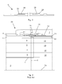
Figure 4 schematically shows a longitudinal cross section of an end of therotor core 3, in correspondence of a retaining ring 7. - In particular
figure 4 shows a part of therotor core 3, delimited by the dashed line 9, with the slots 4 (with their insulation extending outside of the slots) and thewindings 5 housed therein, in addition, theend windings 10 extending outside of theslots 4 and around therotor shaft 2 are also shown. - Within each
slot 4 and above thewindings 5 one or usually more than oneinsulating layers 11 and, above them, thewedge 6, are provided. - Correspondingly, above the
end windings 10 one or usually more than one insulating layers 12 (with a stepped end facing the stepped end of the insulating layers 11) and one or more than oneliner sheets 13 protecting theinsulating layers 12 are provided. - Moreover, in order to short circuit all the
wedges 6 together, aconductive damper ring 14 and a plurality of damper fingers ordamper finger segments 15 are provided (the damper fingers are typically connected to conductive segments that extend outside of the slots; for sake of simplicity in the following damper fingers and segments are globally defined as damper finger segments). The damper fingers segments 15 make direct contact with thewedges 6. - During
operation eddy currents 16 are generated within thewedges 6, they pass into thedamper finger segments 15 and then enter the damper ring 14 (where they circulate tangentially). - In addition, from the damper finger segments 15 a part of the
eddy currents 16 enters the retaining ring 7 and starts to tangentially circulate therein as well. - In particular, since these
eddy currents 16 mainly concentrate within an end 20 (the so called nose) of the retaining ring 7, a great part of theeddy currents 16 entering the retaining ring 7 flows back towards thisend 20, generating electric losses. - The technical aim of the present invention therefore includes providing a rotor, a retaining ring, a wedge and a method addressing the aforementioned problems of the known art.
- Within the scope of this technical aim, an aspect of the invention is to provide a rotor, a retaining ring, a wedge and a method allowing operation with reduced losses caused by eddy currents.
- The technical aim, together with these and further aspects, are attained according to the invention by providing a rotor, a retaining ring, a wedge and a method in accordance with the accompanying claims.
- Further characteristics and advantages of the invention will be more apparent from the description of a preferred but non-exclusive embodiment of the rotor, retaining ring, wedge and method illustrated by way of nonlimiting example in the accompanying drawings, in which:
-
Figure 1 is a schematic view of a rotor of an electric generator; -
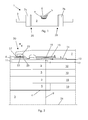
Figure 2 is a schematic cross section of a part of a rotor in an embodiment of the invention; - Figures
figure 3 shows a wedge in an embodiment of the invention; -
Figure 4 shows a schematic cross section of a part of a rotor according to the prior art. - In the following the same reference are used to designate like or corresponding parts as those already previously described.
- The electric generator comprises a
rotor 1 with slots 4 (with their insulations extending outside of the slots)housing windings 5;reference 10 indicates the end windings extending outside of theslots 4. - The
slots 4 are closed by thewedges 6. - In addition, retaining rings 7, encircling the rotor ends 20 to enclose and support the
end windings 10, are provided. - Advantageously, an electric connection between the
end 20 of each retaining ring 7 facing the other retaining ring 7 and thewedges 6 is provided. - In other words, with particular reference to
figure 1 wherein the retaining rings are identified by 7a and 7b, the electric connection is provided between theend 20 of theretaining ring 7a facing theretaining ring 7b and thewedges 6 and likewise between theend 20 of theretaining ring 7b facing theretaining ring 7a and thewedges 6. - In order to define this electric connection, each of the
retaining ring end 20 facing the other retaining ring 7 has aconductive element 22 embedded therein, with apart 23 opening to the central hole of the same retaining ring 7 (for example thepart 23 can protrude within the central hole of the retaining ring 7, but this is not necessary) to make contact with thewedges 6. - The
conductive element 22 comprises a conductive ring preferably made out of copper. - In order to improve the electric connection, the
wedges 6 have elastic portions 25 (at each of their ends) pressing against theconductive elements 22. - In a possible embodiment (shown in the figures) the
elastic portions 25 are arranged to radially expand (i.e. along a radial direction R). - The
elastic portions 25 extend parallel to an electric generatorlongitudinal axis 26 and are defined bylongitudinal cut outs 27 extending parallel to the electric generatorlongitudinal axis 26. - In a further possible embodiment, the
elastic portions 25 can also include one ormore weights 28 embedded therein; during operation theseweights 28 help expansion of theelastic portions 25 under centrifugal load to improve electric connection. - The operation of the electric generator is apparent from that described and illustrated and is substantially the following.
- During operation eddy currents are generated within the
wedges 6. - Thanks to the electric connection achieved via the
element 22, a part of these eddy currents directly flows from thewedges 6 to theend 20 of the retaining rings 7; another part of the eddy currents still reaches thedamper finger segments 15 to then pass into thedamper ring 14 and retaining ring 7 and back to theend 20. - The current path via the
damper finger segments 15 to thedamper ring 14 and the retaining ring 7 is kept because eddy currents at lower frequencies (typically 50/60 Hz and 100/120 Hz) can reach high amplitudes and therefore it is advantageous to keep two parallel paths fromwedges 6 to retaining ring 7. - The higher the frequencies, the more eddy currents will flow via the
direct connection 22 to the retaining ring 7 generating less losses than if the eddy currents have to flow via thedamper finger segments 15 to the retaining ring 7 and back to theend 20. - The present disclosure also refers to a method for reducing the losses in an electric generator.
- The method comprises directly conveying at least part of the eddy currents from the
wedges 6 where they are generated into the retaining ring 7, at retainingring ends 20 facing the other retaining ring 7. - Naturally the features described may be independently provided from one another.
- In practice the materials used and the dimensions can be chosen at will according to requirements and to the state of the art.
-
- 1
- rotor
- 2
- rotor shaft
- 3
- rotor core
- 4
- slots
- 5
- rotor windings
- 6
- wedges
- 7,
- 7a, 7b retaining rings
- 9
- limit of the rotor core
- 10
- end windings
- 11
- insulating layers
- 12
- insulating layers
- 13
- liner sheet
- 14
- damper ring
- 15
- damper finger segments
- 16
- eddy currents
- 20
- ends of 7
- 22
- conductive element
- 23
- part of 22
- 25
- elastic portions of 6
- 26
- electric generator longitudinal axis
- 27
- longitudinal cuts
- 28
- weight
- R
- radial direction
Claims (15)
- Rotor (1) of an electric generator having slots (4) housing windings (5) closed by a wedge (6), and retaining rings (7) encircling the rotor ends (20), characterised by comprising an electric connection between each retaining ring end (20) facing the other retaining ring (7) and the wedges (6).
- Rotor (1) according to claim 1, characterised in that the electric connection is defined by a conductive element (22) embedded in each of the retaining ring end (20) facing the other retaining ring (7) and making contact with the wedges (6).
- Rotor (1) according to claim 2, characterised in that the conductive element (22) comprises a conductive ring.
- Rotor (1) according to claim 2, characterised in that the wedges (6) have elastic portions (25) pressing against the conductive elements (22).
- Rotor (1) according to claim 4, characterised in that the elastic portions (25) are arranged to radially expand.
- Rotor (1) according to claim 5, characterised in that the elastic portions (25) extend parallel to an electric generator longitudinal axis (26) and are defined by longitudinal cut outs (27) extending parallel to an electric generator longitudinal axis (26).
- Rotor (1) according to claim 5, characterised in that the elastic portions (25) include at least a weight (28) embedded therein.
- Retaining ring (7) of a rotor of an electric generator characterised by comprising a conductive element (22) embedded therein and having a part (23) opening to its central hole.
- Retaining ring (7) according to claim 8, characterised in that the conductive element (22) comprises a conductive ring.
- Wedge (6) for an electric generator rotor slot (4), characterised by having at least an elastic portion (25) arranged to expand.
- Wedge (6) according to claim 10, characterised in that when the wedge (6) is inserted into a rotor slot (4) the elastic portion (25) can radially expand.
- Wedge (6) according to claim 11, characterised in that the elastic portions (25) extend parallel to an electric generator longitudinal axis (26) when the wedge (6) is inserted into a rotor slot (4).
- Wedge (6) according to claim 10, characterised in that the elastic portions (25) are defined by cut outs (27) extending parallel to the electric generator longitudinal axis (26) when the wedge (6) is inserted into a rotor slot (4).
- Wedge (6) according to claim 10, characterised in that the elastic portions (25) include at least a weight (28) embedded therein.
- Method for reducing the losses in an electric generator comprising a rotor (1) with slots (4) housing windings (5) closed by wedges (6) and retaining rings (7) encircling the rotor ends, characterised by directly convey at least part of the eddy currents from the wedges (6) where they are generated into the retaining rings (7) at retaining ring ends (20) facing the other retaining ring (7).
Priority Applications (1)
| Application Number | Priority Date | Filing Date | Title |
|---|---|---|---|
| EP10187169A EP2439833A1 (en) | 2010-10-11 | 2010-10-11 | Turbo-generator rotor with retaining rings, wedges and method to reduce eddy currents in such a rotor |
Applications Claiming Priority (1)
| Application Number | Priority Date | Filing Date | Title |
|---|---|---|---|
| EP10187169A EP2439833A1 (en) | 2010-10-11 | 2010-10-11 | Turbo-generator rotor with retaining rings, wedges and method to reduce eddy currents in such a rotor |
Publications (1)
| Publication Number | Publication Date |
|---|---|
| EP2439833A1 true EP2439833A1 (en) | 2012-04-11 |
Family
ID=43735808
Family Applications (1)
| Application Number | Title | Priority Date | Filing Date |
|---|---|---|---|
| EP10187169A Withdrawn EP2439833A1 (en) | 2010-10-11 | 2010-10-11 | Turbo-generator rotor with retaining rings, wedges and method to reduce eddy currents in such a rotor |
Country Status (1)
| Country | Link |
|---|---|
| EP (1) | EP2439833A1 (en) |
Cited By (1)
| Publication number | Priority date | Publication date | Assignee | Title |
|---|---|---|---|---|
| CN116982244A (en) * | 2021-03-17 | 2023-10-31 | 西门子能源美国公司 | Generator with high pressure air cooling |
Citations (2)
| Publication number | Priority date | Publication date | Assignee | Title |
|---|---|---|---|---|
| US5118979A (en) * | 1990-12-18 | 1992-06-02 | General Electric Company | Cantilever spring contact for retaining rings on dynamoelectric machine |
| US5430340A (en) * | 1993-04-15 | 1995-07-04 | General Electric Co. | Harmonic current path spring device between retaining ring and rotor wedge of a dynamoelectric generator |
-
2010
- 2010-10-11 EP EP10187169A patent/EP2439833A1/en not_active Withdrawn
Patent Citations (2)
| Publication number | Priority date | Publication date | Assignee | Title |
|---|---|---|---|---|
| US5118979A (en) * | 1990-12-18 | 1992-06-02 | General Electric Company | Cantilever spring contact for retaining rings on dynamoelectric machine |
| US5430340A (en) * | 1993-04-15 | 1995-07-04 | General Electric Co. | Harmonic current path spring device between retaining ring and rotor wedge of a dynamoelectric generator |
Cited By (1)
| Publication number | Priority date | Publication date | Assignee | Title |
|---|---|---|---|---|
| CN116982244A (en) * | 2021-03-17 | 2023-10-31 | 西门子能源美国公司 | Generator with high pressure air cooling |
Similar Documents
| Publication | Publication Date | Title |
|---|---|---|
| JP2006529076A (en) | Electric machine | |
| US20150035406A1 (en) | Electric machine with a slot liner | |
| CN101728911A (en) | Fault tolerant permanent magnet machine | |
| EP2871755B1 (en) | Rotating machinery | |
| CN111919363B (en) | Combination of an AC motor and a converter unit and wind power plant | |
| CN106030995B (en) | Support component and stator module including it | |
| US20200328645A1 (en) | Electric machine element and an electric machine | |
| EP2787607A2 (en) | Electric machine rotor | |
| EP3011662B1 (en) | Rotor for a rotating electrical machine | |
| US9859776B2 (en) | Starting current reduction in induction motors | |
| JP2008253014A (en) | High voltage rotating electrical machine | |
| US4281266A (en) | Dynamoelectric machine with flux screen | |
| EP4024673B1 (en) | Wedge for rotor field coils and rotor comprising the same | |
| US3610977A (en) | Synchronous machine having salient rotor poles | |
| EP3179608B1 (en) | Rotating machinery | |
| JP7085845B2 (en) | Rotating machine stator and rotating machine | |
| EP2528201A1 (en) | Method for applying a retaining system above a rotor core of an electric machine and rotor assembly | |
| US20050046300A1 (en) | Reduction of core-end losses of dynamoelectric machines by using lower core loss iron silicon punching | |
| EP2355307B1 (en) | Multi-speed induction motor | |
| EP3109975B1 (en) | End winding support for an electric generator | |
| EP2950424A1 (en) | Chamber for conductors of electric machines | |
| EP3618231B1 (en) | Rotating machinery | |
| US9525328B2 (en) | Rotating electric machine, in particular double-fed asynchronous machine with a power range of between 20 MVA and 500 MVA | |
| JPWO2019225156A1 (en) | Rotating machine and manufacturing method of rotating machine | |
| US11532964B2 (en) | Generator rotor flat wire winding |
Legal Events
| Date | Code | Title | Description |
|---|---|---|---|
| AK | Designated contracting states |
Kind code of ref document: A1 Designated state(s): AL AT BE BG CH CY CZ DE DK EE ES FI FR GB GR HR HU IE IS IT LI LT LU LV MC MK MT NL NO PL PT RO RS SE SI SK SM TR |
|
| AX | Request for extension of the european patent |
Extension state: BA ME |
|
| PUAI | Public reference made under article 153(3) epc to a published international application that has entered the european phase |
Free format text: ORIGINAL CODE: 0009012 |
|
| STAA | Information on the status of an ep patent application or granted ep patent |
Free format text: STATUS: THE APPLICATION IS DEEMED TO BE WITHDRAWN |
|
| 18D | Application deemed to be withdrawn |
Effective date: 20121012 |