EP2439826A1 - cable entry seal for motor-driven compressor - Google Patents
cable entry seal for motor-driven compressor Download PDFInfo
- Publication number
- EP2439826A1 EP2439826A1 EP11183921A EP11183921A EP2439826A1 EP 2439826 A1 EP2439826 A1 EP 2439826A1 EP 11183921 A EP11183921 A EP 11183921A EP 11183921 A EP11183921 A EP 11183921A EP 2439826 A1 EP2439826 A1 EP 2439826A1
- Authority
- EP
- European Patent Office
- Prior art keywords
- seal
- seal portion
- case
- conductor
- case member
- Prior art date
- Legal status (The legal status is an assumption and is not a legal conclusion. Google has not performed a legal analysis and makes no representation as to the accuracy of the status listed.)
- Granted
Links
- 239000004020 conductor Substances 0.000 claims abstract description 45
- 238000007789 sealing Methods 0.000 claims abstract description 16
- 230000002093 peripheral effect Effects 0.000 claims description 38
- 238000005192 partition Methods 0.000 claims description 20
- 239000003507 refrigerant Substances 0.000 description 13
- 239000012212 insulator Substances 0.000 description 12
- 230000006835 compression Effects 0.000 description 4
- 238000007906 compression Methods 0.000 description 4
- WABPQHHGFIMREM-UHFFFAOYSA-N lead(0) Chemical compound [Pb] WABPQHHGFIMREM-UHFFFAOYSA-N 0.000 description 3
- 239000007788 liquid Substances 0.000 description 3
- 229920005989 resin Polymers 0.000 description 3
- 239000011347 resin Substances 0.000 description 3
- 230000000694 effects Effects 0.000 description 2
- 238000010292 electrical insulation Methods 0.000 description 2
- 239000000463 material Substances 0.000 description 2
- 238000000034 method Methods 0.000 description 2
- 230000005489 elastic deformation Effects 0.000 description 1
- 239000003822 epoxy resin Substances 0.000 description 1
- 239000011521 glass Substances 0.000 description 1
- 238000010438 heat treatment Methods 0.000 description 1
- 238000007654 immersion Methods 0.000 description 1
- 238000004519 manufacturing process Methods 0.000 description 1
- 239000002184 metal Substances 0.000 description 1
- 229920000647 polyepoxide Polymers 0.000 description 1
- 230000002265 prevention Effects 0.000 description 1
- 229920003002 synthetic resin Polymers 0.000 description 1
- 239000000057 synthetic resin Substances 0.000 description 1
- 229920001187 thermosetting polymer Polymers 0.000 description 1
Images




Classifications
-
- H—ELECTRICITY
- H02—GENERATION; CONVERSION OR DISTRIBUTION OF ELECTRIC POWER
- H02G—INSTALLATION OF ELECTRIC CABLES OR LINES, OR OF COMBINED OPTICAL AND ELECTRIC CABLES OR LINES
- H02G15/00—Cable fittings
- H02G15/013—Sealing means for cable inlets
-
- F—MECHANICAL ENGINEERING; LIGHTING; HEATING; WEAPONS; BLASTING
- F04—POSITIVE - DISPLACEMENT MACHINES FOR LIQUIDS; PUMPS FOR LIQUIDS OR ELASTIC FLUIDS
- F04C—ROTARY-PISTON, OR OSCILLATING-PISTON, POSITIVE-DISPLACEMENT MACHINES FOR LIQUIDS; ROTARY-PISTON, OR OSCILLATING-PISTON, POSITIVE-DISPLACEMENT PUMPS
- F04C29/00—Component parts, details or accessories of pumps or pumping installations, not provided for in groups F04C18/00 - F04C28/00
-
- F—MECHANICAL ENGINEERING; LIGHTING; HEATING; WEAPONS; BLASTING
- F04—POSITIVE - DISPLACEMENT MACHINES FOR LIQUIDS; PUMPS FOR LIQUIDS OR ELASTIC FLUIDS
- F04B—POSITIVE-DISPLACEMENT MACHINES FOR LIQUIDS; PUMPS
- F04B35/00—Piston pumps specially adapted for elastic fluids and characterised by the driving means to their working members, or by combination with, or adaptation to, specific driving engines or motors, not otherwise provided for
- F04B35/04—Piston pumps specially adapted for elastic fluids and characterised by the driving means to their working members, or by combination with, or adaptation to, specific driving engines or motors, not otherwise provided for the means being electric
-
- F—MECHANICAL ENGINEERING; LIGHTING; HEATING; WEAPONS; BLASTING
- F04—POSITIVE - DISPLACEMENT MACHINES FOR LIQUIDS; PUMPS FOR LIQUIDS OR ELASTIC FLUIDS
- F04B—POSITIVE-DISPLACEMENT MACHINES FOR LIQUIDS; PUMPS
- F04B39/00—Component parts, details, or accessories, of pumps or pumping systems specially adapted for elastic fluids, not otherwise provided for in, or of interest apart from, groups F04B25/00 - F04B37/00
- F04B39/12—Casings; Cylinders; Cylinder heads; Fluid connections
-
- F—MECHANICAL ENGINEERING; LIGHTING; HEATING; WEAPONS; BLASTING
- F04—POSITIVE - DISPLACEMENT MACHINES FOR LIQUIDS; PUMPS FOR LIQUIDS OR ELASTIC FLUIDS
- F04B—POSITIVE-DISPLACEMENT MACHINES FOR LIQUIDS; PUMPS
- F04B39/00—Component parts, details, or accessories, of pumps or pumping systems specially adapted for elastic fluids, not otherwise provided for in, or of interest apart from, groups F04B25/00 - F04B37/00
- F04B39/12—Casings; Cylinders; Cylinder heads; Fluid connections
- F04B39/121—Casings
-
- F—MECHANICAL ENGINEERING; LIGHTING; HEATING; WEAPONS; BLASTING
- F04—POSITIVE - DISPLACEMENT MACHINES FOR LIQUIDS; PUMPS FOR LIQUIDS OR ELASTIC FLUIDS
- F04C—ROTARY-PISTON, OR OSCILLATING-PISTON, POSITIVE-DISPLACEMENT MACHINES FOR LIQUIDS; ROTARY-PISTON, OR OSCILLATING-PISTON, POSITIVE-DISPLACEMENT PUMPS
- F04C18/00—Rotary-piston pumps specially adapted for elastic fluids
- F04C18/02—Rotary-piston pumps specially adapted for elastic fluids of arcuate-engagement type, i.e. with circular translatory movement of co-operating members, each member having the same number of teeth or tooth-equivalents
-
- F—MECHANICAL ENGINEERING; LIGHTING; HEATING; WEAPONS; BLASTING
- F04—POSITIVE - DISPLACEMENT MACHINES FOR LIQUIDS; PUMPS FOR LIQUIDS OR ELASTIC FLUIDS
- F04C—ROTARY-PISTON, OR OSCILLATING-PISTON, POSITIVE-DISPLACEMENT MACHINES FOR LIQUIDS; ROTARY-PISTON, OR OSCILLATING-PISTON, POSITIVE-DISPLACEMENT PUMPS
- F04C23/00—Combinations of two or more pumps, each being of rotary-piston or oscillating-piston type, specially adapted for elastic fluids; Pumping installations specially adapted for elastic fluids; Multi-stage pumps specially adapted for elastic fluids
- F04C23/008—Hermetic pumps
-
- H—ELECTRICITY
- H02—GENERATION; CONVERSION OR DISTRIBUTION OF ELECTRIC POWER
- H02K—DYNAMO-ELECTRIC MACHINES
- H02K5/00—Casings; Enclosures; Supports
- H02K5/04—Casings or enclosures characterised by the shape, form or construction thereof
- H02K5/22—Auxiliary parts of casings not covered by groups H02K5/06-H02K5/20, e.g. shaped to form connection boxes or terminal boxes
-
- F—MECHANICAL ENGINEERING; LIGHTING; HEATING; WEAPONS; BLASTING
- F04—POSITIVE - DISPLACEMENT MACHINES FOR LIQUIDS; PUMPS FOR LIQUIDS OR ELASTIC FLUIDS
- F04C—ROTARY-PISTON, OR OSCILLATING-PISTON, POSITIVE-DISPLACEMENT MACHINES FOR LIQUIDS; ROTARY-PISTON, OR OSCILLATING-PISTON, POSITIVE-DISPLACEMENT PUMPS
- F04C18/00—Rotary-piston pumps specially adapted for elastic fluids
- F04C18/02—Rotary-piston pumps specially adapted for elastic fluids of arcuate-engagement type, i.e. with circular translatory movement of co-operating members, each member having the same number of teeth or tooth-equivalents
- F04C18/0207—Rotary-piston pumps specially adapted for elastic fluids of arcuate-engagement type, i.e. with circular translatory movement of co-operating members, each member having the same number of teeth or tooth-equivalents both members having co-operating elements in spiral form
- F04C18/0215—Rotary-piston pumps specially adapted for elastic fluids of arcuate-engagement type, i.e. with circular translatory movement of co-operating members, each member having the same number of teeth or tooth-equivalents both members having co-operating elements in spiral form where only one member is moving
-
- F—MECHANICAL ENGINEERING; LIGHTING; HEATING; WEAPONS; BLASTING
- F04—POSITIVE - DISPLACEMENT MACHINES FOR LIQUIDS; PUMPS FOR LIQUIDS OR ELASTIC FLUIDS
- F04C—ROTARY-PISTON, OR OSCILLATING-PISTON, POSITIVE-DISPLACEMENT MACHINES FOR LIQUIDS; ROTARY-PISTON, OR OSCILLATING-PISTON, POSITIVE-DISPLACEMENT PUMPS
- F04C2240/00—Components
- F04C2240/80—Other components
- F04C2240/803—Electric connectors or cables; Fittings therefor
Definitions
- the present invention relates to a motor-driven compressor having a shell receiving therein an electric motor that is electrically connected to a power source located outside the shell.
- a first conductor connected to the power supply extends through the shell, and a second conductor connected to the electric motor is connected to the first conductor in the shell.
- refrigerant gas existing in the compressor or within the shell may be cooled and liquefied, and such liquefied refrigerant may remain in the compressor.
- major part of the second conductor is covered by an insulator, immersion of the connection between the first and the second conductors in the liquid refrigerant may cause electrical leakage between the first and the second conductors.
- the second conductor or a motor lead wire is connected to a spring terminal, and part of the first conductor that is located in the shell is inserted in the spring terminal and electrically connected to the spring terminal.
- the spring terminal is covered by a heat-shrinkable tube in the shell. The tube shrinks when heated by operation of the compressor, thereby preventing contact between the conductors and liquid refrigerant in the shell.
- sealing provided by the shrinkage of the tube is not enough to prevent electrical leakage in the shell.
- Good sealing may be accomplished, for example, by covering the spring terminal using thermosetting resin such as epoxy resin and then setting the resin by heating. However, this procedure is troublesome.
- the present invention is directed to providing a motor-driven compressor that provides improved and simple sealing of electrical connection between a first and a second conductors in a shell of the compressor.
- a motor-driven compressor includes a shell, an electric motor provided in the shell, a first conductor extended through the shell and electrically connected to an external power source, a second conductor electrically connected to the electric motor, a connector connecting the first conductor and the second conductor and a connector case receiving the connector.
- the connector case has a first case member including a first seal surface extending along the periphery of the first case member, a second case member including a second seal surface extending along the periphery of the second case member and facing the first seal surface, a first seal member interposed between the first and second case members and having a first main seal that is joined to the first seal surface, a second seal member interposed between the first and second case members and having a second main seal that is joined to the second seal surface, a hole through which the first conductor is inserted and a third seal member provided in the connector case and sealing between the first conductor and the connector case.
- the first main seal and the second main seal cooperate to form a cylindrical seal portion for sealing the second conductor that is inserted through the cylindrical seal portion when the first and the second seal members are joined.
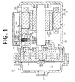
- the scroll-type motor-driven compressor designated generally by 10 has a generally cylindrical shell 14 receiving therein an electric machine or an electric motor M.
- the shell 14 is composed of a motor housing 26 and a front housing 27 connected to the front end of the motor housing 26.
- the electric motor M includes a rotary shaft 12, a rotor 11 fixedly mounted on the rotary shaft 12 and a stator 13 fixed on the inner peripheral surface of the motor housing 26.
- the compressor 10 has a movable scroll 15 and a fixed scroll 16 cooperating to form therebetween compression chambers 17.
- the movable scroll 15 makes an orbital motion relative to the fixed scroll 16 by the rotation of the rotary shaft 12 so that the volumes of the compression chambers 17 are varied.
- the motor housing 26 has formed therethrough an inlet port 261 through which refrigerant gas is introduced from an external refrigerant circuit (not shown) into the motor housing 26.
- Refrigerant gas introduced into the motor housing 26 is flowed into the compression chamber 17 through a passage (not shown) between the inner peripheral surface of the motor housing 26 and the outer peripheral surface of the stator 13 and then a suction port 18 with the revolution of the movable scroll 15.
- the compressed refrigerant gas is discharged out from the central compression chamber 17 into a discharge chamber 21 formed in the front housing 27 through a discharge port 19 while pushing open a discharge valve 20, with the revolution of the movable scroll 15.
- the refrigerant gas flows out of the discharge chamber 21 through an outlet port 271 of the front housing 27 into the external refrigerant circuit, through which the refrigerant gas flows back into the motor housing 26.
- the stator of the electric motor M is composed of a ring-shaped stator core 22 and a coil 23 wound around the stator core 22.
- the rotor 11 of the electric motor M is composed of a rotor core 24 and plural permanent magnets 25 embedded in the rotor core 24.
- the rotor core 24 has formed therethrough a central hole 241 through which the rotary shaft 12 is inserted and fixed.
- a cover 28 is provided on the outer peripheral surface of the motor housing 26.
- An inverter 29 as an external power source is mounted on the inner surface of the upper wall 281 of the cover 28.
- Part of the motor housing 26 that is covered with the cover 28 has formed therethrough a hole 30.
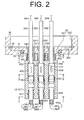
- the hole 30 is stepped, having a large-diameter portion 301 located on the side adjacent to the outer peripheral surface of the motor housing 26, a small-diameter portion 302 located on the side adjacent to the inner peripheral surface of the motor housing 26 and a step 303 located between the large-diameter portion 301 and the small-diameter portion 302.
- a base 31 and a circlip 32 are provided in the large-diameter portion 301.
- the base 31 is placed on the step 303 and held in place by the circlip 32.
- a seal ring 33 is provided between the outer periphery of the base 31 and the inner periphery of the large-diameter portion 301 to prevent leakage of refrigerant gas along the outer periphery of the base 31.
- Three tubular insulators 34U, 34V, 34W made of, for example, a glass are inserted through and fixed to the base 31.
- Three conductive pins 35U, 35V, 35W as a first conductor are inserted through and fixed to the respective insulators 34U, 34V, 34W.
- One ends of the conductive pins 35U, 35V, 35W extend radially out of the shell 14 through the insulators 34U, 34V, 34W, and the other ends of the conductive pins 35U, 35V, 35W extend radially inward into the shell 14 through the insulators 34U, 34V, 34W.
- the ends of the conductive pins 35U, 35V, 35W outside the shell 14 are electrically connected to the inverter 29 (see FIG. 1 ) through electric wires 36U, 36Y, 36W, respectively.
- the coil 23 is composed of a U-phase coil, a V-phase coil and a W-phase coil, each having a lead wire 37 (only one lead wire being shown in the drawing) electrically connected to a terminal 38 to which conductive members 39U, 39V, 39W as a second conductor are electrically connected.
- each of the conductive members 39U, 39V, 39W is composed of a core 391 and an insulator 392 covering the core 391.
- the cores 391 of the conductive members 39U, 39V, 39W are connected to connectors 40U, 40V, 40W to which the ends of the conductive pins 35U, 35V, 35W are connected, respectively.
- the connectors 40U, 40V, 40W are made of a metal.
- the cores 391 of the conductive members 39U, 39V, 39W are electrically connected through the connectors 40U, 40V, 40W to the ends of the conductive pins 35U, 35Y, 35W, respectively.
- the connectors 40U, 40V, 40W are received in a connector case 41.
- the conductive pin 35U, the conductive member 39U and the connector 40U serve as a U-phase conductor of the present invention.
- the conductive pin 35V, the conductive member 39V and the connector 40V serve as a V-phase conductor of the present invention
- the conductive pin 35W, the conductive member 39W and the connector 40W serve as a W-phase conductor of the present invention.
- Electric power is supplied from the inverter 29 through the conductive pins 35U, 35V, 35W, the connectors 40U, 40V, 40W and the conductive members 39U, 39V, 39W to the coil 23, respectively, so that the rotor 11 is rotated together with the rotary shaft 12.
- the connector case 41 is composed of a first case member 42 and a second case member 43 both of which are made of a resin.
- First and second seal members 44, 45 both of which are rectangular-shaped and made of a rubber are interposed between the first and the second case members 42, 43.
- the first case member 42 is formed integrally therewith cylindrical portions 421 U, 421V, 421W through which cylindrical third seal members 46U, 46V, 46W made of a rubber are inserted, respectively.
- the interior of the third seal members 46U, 46V, 46W communicate with the interior of the connector case 41 and the conductive pins 35U, 35V, 35W are inserted through the third seal members 46U, 46V, 46W, respectively.
- FIG. 4A is the exploded plan view of the connector case 41 and FIG. 4B is the plan view of the first seal member 44, the second seal member 45 and the connectors 40U, 40V, 40W.
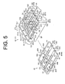
- FIG. 5 is the exploded perspective view of the connector case 41.
- the first case member 42 is of a generally rectangular shape having on one short side 47 thereof a coated wall 471 with a stepped outer seal surface 472 and on the other short side 48 thereof a coated wall 481 with a stepped outer seal surface 482.
- the first case member 42 also has on one long side 53 thereof coated walls 531, 532 with a stepped outer seal surface 533 and on the other long side 54 thereof coated walls 541, 542 with a stepped outer seal surface 543.
- the first case member 42 has formed through the coated wall 477 thereof holes 49U, 49V, 49W and in the bottom thereof third recesses 52U, 52V, 52W communicating with the interiors of the cylindrical portions 421 U, 421V, 421W through the holes 49U, 49V, 49W, respectively.
- the conductive pins 35U, 35V, 35W are inserted through the holes 49U, 49V, 49W, passing axially through the cylindrical portions 421 U, 421V, 421W, respectively.
- the first case member 42 has formed in the bottom thereof second recesses 51 U, 51V, 51W that are continuous with the third recesses 52U, 52V, 52W, respectively.
- the first case member 42 has also formed in the short side 48 thereof first recesses 50U, 50V, 50W that are continuous with the second recesses 51 U, 51V, 51W, respectively, so that the first recesses 50U, 50V, 50W communicate with the holes 49U, 49V, 49W through the second recesses 51 U, 51V, 51W and the third recesses 52U, 52V, 52W, respectively.
- a pair of hooks 55 are formed extending upward from the bottom of each of the second recesses 51U, 51V, 51W.
- Three sets of the first, the second and the third recesses i.e. 50U, 51 U and 52U, 50V, 51V and 52V, and 50W, 51W and 52W, are defined by the outer seal surfaces 533, 543 on the respective long sides 53, 54, a pair of inner seal surfaces 56 and the outer seal surfaces 472, 482 on the respective short sides 47, 48.
- the first case member 42 is formed with catches 57, 58 projecting from the outer seal surfaces 533, 543 of the long sides 53, 54, respectively.
- First grooves 561 are formed in the respective inner seal surfaces 56 and a third groove 501 is formed in each of the first recesses 50U, 50V, 50W and the inner seal surface 56 so as to extend in a direction perpendicular to the extending direction of the first groove 561.
- the second case member 43 is formed in a generally rectangular shape that can be fitted within the coated walls 471, 481, 531, 532, 541, 542 of the first case member 42.
- the second case member 43 has formed therein fourth recesses 59U, 59V, 59W and fifth recesses 60U, 60V, 60W so that the fourth recesses 59U, 59V, 59W are continuous with the fifth recesses 60U, 60V, 60W, respectively.
- the connectors 40U, 40V, 40W are fitted in the fourth recesses 59U, 59V, 59W and the fifth recesses 60U, 60V, 60W, respectively.
- Three sets of the recesses i.e. 59U and 60U, 59V and 60V, and 59W and 60W are defined by a pair of outer seal surfaces 61, 62 on the long side of the second case member 43, an outer seal surface 63 on the short side and a pair of inner seal surfaces 64.
- a second groove 641 is formed in each of the inner seal surfaces 64.
- Hooks 65A, 65B that are engageable with the catches 57, 58, respectively, are formed projecting horizontally outward from the respective long sides.
- a pair of third projections 66A, 66B are formed projecting upward from each long side of the second case member 43 so as to place the hooks 65A, 65B between the respective pair of the third projections 66A, 66B.
- the catches 57, 58 and the hooks 65A, 65B correspond to engaging members of the present invention.
- a plurality of holes 473, 483 are formed through the coated walls 471, 481 of the first case member 42, respectively.
- a plurality of projections 431, 432 that are engageable with the holes 473, 483, respectively, are formed projecting horizontally outward from the respective short sides of the second case member 43.
- the first seal member 44 made of a rubber is formed in a generally rectangular shape so as to be fitted within the coated walls 471, 481, 531, 532, 541, 542 of the first case member 42.
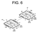
- the first seal member 44 has at the short sides thereof first and second peripheral seal portions 69, 68 and at the long side thereof first and second side seal portions 71, 72, respectively.
- the first seal member 44 further has a pair of first partition seal portions 70 formed between the first and the second peripheral seal portions 69, 68 so as to be continuous therewith.
- the pair of first partition seal portions 70 extend parallel to the first and second side seal portions 71, 72.
- the second peripheral seal portion 68 includes three semicircular seal portions 68U, 68V, 68W.
- a projection 681 is formed projecting from the convex surface (or rear surface) side of each of the semicircular seal portions 68U, 68V, 68W of the first seal member 44 so as to be fittable into the third groove 501 of the first case member 42.
- the first peripheral seal portion 69 is located opposite from the second peripheral seal portion 68.
- First and second tabs 73A, 73B are formed projecting horizontally outward from the first and the second side seal portions 71, 72 on the long sides of the first seal member 44 so as to be engageable with the catches 57, 58 of the first case member 42, respectively.
- the second seal member 45 made of a rubber is formed in a generally rectangular shape so as to be fitted within the coated walls 471, 481, 531, 532, 541, 542 of the first case member 42.
- the second seal member 45 has at the short sides thereof fourth and third peripheral seal portions 74, 75 and at the long sides thereof third and fourth side seal portions 77, 78, respectively.
- a pair of second partition seal portions 76 are formed between the fourth and the third peripheral seal portions 74, 75 so as to be continuous therewith.
- the pair of second partition seal portions 76 extend parallel to the third and the fourth side seal portions 77, 78.
- the fourth peripheral seal portion 74 has three semicircular seal portions 74U, 74V, 74W.
- the third peripheral seal portion 75 is located opposite from the fourth peripheral seal portion 74.
- Third and fourth tabs 79A, 79B are formed projecting horizontally outward from the third and the fourth side seal portions 77, 78 on the long sides of the second seal member 45.
- the third and the fourth tabs 79A, 79B are engageable with the third projections 66A, 66B of the second case member 43, respectively.
- a first projection 701 is formed in each first partition seal portion 70 of the first seal member 44 on the rear surface side thereof so as to be engageable with the first groove 561 of the first case member 42.
- a second projection 761 is formed in each second partition seal portion 76 of the second seal member 45 on the rear surface side thereof so as to be engageable with the second groove 641 of the second case member 43.
- the first seal member 44 and the second seal member 45 are joined together in a manner that the concave surfaces of the semicircular seal portions 68U, 68V, 68W as the first semicircular seal portion of the present invention face the concave surfaces of the semicircular seal portions 74U, 74V, 74W as the second semicircular seal portion of the present invention, respectively, and also the paired first partition seal portions 70 face the paired second partition seal portions 76, respectively.
- the semicircular seal portions 68U, 68V, 68W of the first seal member 44 and the semicircular seal portions 74U, 74V, 74W of the second seal member 45 cooperate to form cylindrical seal portions 80U, 80V, 80W, respectively.
- the first seal member 44 is fitted within the coated walls 471, 481, 531, 532, 541, 542.
- the second seal member 45 is joined to the second case member 43 so as to be in contact with the outer seal surfaces 61, 62, 63, 64 of the second seal member 43.
- the first seal member 44 fitted within the coated walls 471, 481, 531, 532, 541, 542 of the first case member 42, the first and the second tabs 73A, 73B of the first seal member 44 are engaged with the catches 57, 58 of the first case member 42, respectively.
- first projections 701 of the first seal member 44 are engaged with the first grooves 561 of the first case member 42 and the projections 681 of the first seal member 44 are engaged with the third groove 501 of the first case member 42.
- the second seal member 45 joined to the second case member 43, the third and the fourth tabs 79A, 79B of the second seal member 45 are engaged with the third projections 66A, 66B of the second case member 43, respectively, and the second projections 761 of the second seal member 45 are engaged with the second grooves 641 of the second case member 43.
- the connectors 40U, 40V, 40W connected to the cores 391 of the conductive members 39U, 39V, 39W, respectively, are held between the paired hooks 55 of the first case member 42 so that the insulators 392 contact with the semicircular seal portions 68U, 68V, 68W of the first seal member 44.
- the second case member 43 is joined to the first case member 42 so that the second case member 43 is held within the coated walls 471, 481, 531, 532, 541, 542 of the first case member 42 and the hooks 65A, 65B of the second case member 43 are engaged with the catches 57, 58 of the first case member 42.
- the insulators 392 are held between the semicircular seal portions 68U, 68V, 68W of the first seal member 44 and between the semicircular seal portions 74U, 74V, 74W of the second seal member 45, respectively.
- the cylindrical third seal members 46U, 46V, 46W are inserted into the cylindrical portions 421 U, 421V, 421W of the first case member 42, respectively.
- the insulators 34U, 34V, 34W are inserted into the connector case 41 through the third seal members 46U, 46V, 46W, and the conductive pins 35U, 35V, 35W are inserted into the connectors 40U, 40V, 40W, respectively, for connection thereto.
- the third seal members 46U, 46V, 46W seal around the insulators 34U, 34V, 34W, respectively.
- the first side seal portion 71 of the first seal member 44 and the third side seal portion 77 of the second seal member 45 are held between the outer seal surface 533 of the first case member 42 and the outer seal surface 61 of the second case member 43.
- the second side seal portion 72 of the first seal member 44 and the fourth side seal portion 78 of the second seal member 45 are held between the outer seal surface 543 of the first case member 42 and the outer seal surface 62 of the second case member 43.
- the first peripheral seal portion 69 of the first seal member 44 and the peripheral seal portion 75 of the second seal member 45 are held between the outer seal surface 472 of the first case member 42 and the outer seal surface 63 of the second case member 43.
- the semicircular seal portions 68U, 68V, 68W of the first seal member 44 and the semicircular seal portions 74U, 74V, 74W of the second seal member 45 are held between the first recesses 50U, 50V, 50W of the first case member 42 and the fourth recesses 59U, 59V, 59W of the second case member 43.
- the first partition seal portions 70 of the first seal member 44 and the second partition seal portions 76 of the second seal member 45 are held between the inner seal surface 56 of the first case member 42 and the inner seal surface 64 of the second case member 43
- first and the second seal members 44, 45 seal between the peripheries of the first and the second case members 42, 43 in the connector case 41 and electrically insulate between any two adjacent connectors 40U, 40V, 40W by the first and the second partition seal portions 70, 76.
- the outer seal surfaces 472, 482, 533, 543, the first recesses 50U, 50V, 50W and the inner seal surfaces 56 cooperate to form an annular first seal surface extending along the periphery of the first case member 42.
- the outer seal surfaces 61, 62, 63, the fourth recesses 59U, 59V, 59W and the inner seal surfaces 64 cooperate to form an annular second seal surface extending along the periphery of the second case member 43 and facing the first seal surface.
- the first peripheral seal portion 69, the first side seal portion 71, the second side seal portion 72 and the semicircular seal portions 68U, 68V, 68W cooperate to form a first main seal that is joined to the first seal surface of the first case member 42.
- the peripheral seal portion 75, the third side seal portion 77, the fourth side seal portion 78 and the semicircular seal portions 74U, 74V, 74W cooperate to form a second main seal that is joined to the second seal surface of the second case member 43.
- the motor-driven compressor according to the first embodiment of the present invention offers the following advantageous effects.
- a motor-driven compressor includes a shell, an electric motor provided in the shell, a first conductor extended through the shell and electrically connected to an external power source, a second conductor electrically connected to the electric motor, a connector connecting the first conductor and the second conductor and a connector case receiving the connector.
- the connector case has a first case member including a first seal surface extending along the periphery of the first case member, a second case member including a second seal surface extending along the periphery of the second case member and facing the first seal surface, a first seal member interposed between the first and second case members and having a first main seal that is joined to the first seal surface, a second seal member interposed between the first and second case members and having a second main seal that is joined to the second seal surface, a hole through which the first conductor is inserted and a third seal member provided in the connector case and sealing between the first conductor and the connector case.
- the first main seal and the second main seal cooperate to form a cylindrical seal portion for sealing the second conductor that is inserted through the cylindrical seal portion when the first and the second seal members are joined.
Landscapes
- Engineering & Computer Science (AREA)
- Mechanical Engineering (AREA)
- General Engineering & Computer Science (AREA)
- Power Engineering (AREA)
- Compressor (AREA)
- Connector Housings Or Holding Contact Members (AREA)
Abstract
Description
- The present invention relates to a motor-driven compressor having a shell receiving therein an electric motor that is electrically connected to a power source located outside the shell.
- In such kind of compressor, a first conductor connected to the power supply extends through the shell, and a second conductor connected to the electric motor is connected to the first conductor in the shell.
- When the compressor is left stopped for a long time, refrigerant gas existing in the compressor or within the shell may be cooled and liquefied, and such liquefied refrigerant may remain in the compressor. Although major part of the second conductor is covered by an insulator, immersion of the connection between the first and the second conductors in the liquid refrigerant may cause electrical leakage between the first and the second conductors.
- In the compressor disclosed in Japanese Unexamined Patent Application Publication NO.
05-256261 - However, sealing provided by the shrinkage of the tube is not enough to prevent electrical leakage in the shell. Good sealing may be accomplished, for example, by covering the spring terminal using thermosetting resin such as epoxy resin and then setting the resin by heating. However, this procedure is troublesome.
- The present invention is directed to providing a motor-driven compressor that provides improved and simple sealing of electrical connection between a first and a second conductors in a shell of the compressor.
- A motor-driven compressor includes a shell, an electric motor provided in the shell, a first conductor extended through the shell and electrically connected to an external power source, a second conductor electrically connected to the electric motor, a connector connecting the first conductor and the second conductor and a connector case receiving the connector. The connector case has a first case member including a first seal surface extending along the periphery of the first case member, a second case member including a second seal surface extending along the periphery of the second case member and facing the first seal surface, a first seal member interposed between the first and second case members and having a first main seal that is joined to the first seal surface, a second seal member interposed between the first and second case members and having a second main seal that is joined to the second seal surface, a hole through which the first conductor is inserted and a third seal member provided in the connector case and sealing between the first conductor and the connector case. The first main seal and the second main seal cooperate to form a cylindrical seal portion for sealing the second conductor that is inserted through the cylindrical seal portion when the first and the second seal members are joined.
- Other aspects and advantages of the invention will become apparent from the following description, taken in conjunction with the accompanying drawings, illustrating by way of example the principles of the invention.
- The features of the present invention that are believed to be novel are set forth with particularity in the appended claims. The invention together with objects and advantages thereof, may best be understood by reference to the following description of the presently preferred embodiments together with the accompanying drawings in which:
-
FIG. 1 is a longitudinal sectional view of a motor-driven compressor according to a first embodiment of the present invention; -
FIG. 2 is an enlarged fragmentary sectional view of the compressor ofFIG. 1 ; -
FIG. 3A is a cross-sectional view taken along the line A-A ofFIG. 2 ; -
FIG. 3B is a cross-sectional view taken along the line B-B ofFIG. 2 ; -
FIG. 3C is a cross-sectional view taken along the line C-C ofFIG. 2 ; -
FIG. 4A is an exploded plan view of a connector case; -
FIG. 4B is a plan view of a first seal member, a second seal member and connectors; -
FIG. 5 is an exploded perspective view of the connector case; -
FIG. 6 is a perspective view of the first and the second seal members; -
FIG. 7 is another perspective view of the first and the second seal members; -
FIG. 8A is a perspective view of a first case member to which the first seal member is mounted; -
FIG. 8B is a perspective view of a second case member to which the second seal member is mounted; -
FIG. 9 is a perspective view of another embodiment of the first and the second seal members; -
FIG. 10 is a perspective view of still another embodiment of the seal member; and -
FIG. 11 is a perspective view of yet another embodiment of the first and the second seal members. - The following will describe the first embodiment of the motor-driven compressor according to the present invention with reference to
FIGS. 1 through 8 . Referring toFIG. 1 , the scroll-type motor-driven compressor designated generally by 10 has a generallycylindrical shell 14 receiving therein an electric machine or an electric motor M. Theshell 14 is composed of amotor housing 26 and afront housing 27 connected to the front end of themotor housing 26. - The electric motor M includes a
rotary shaft 12, a rotor 11 fixedly mounted on therotary shaft 12 and astator 13 fixed on the inner peripheral surface of themotor housing 26. Thecompressor 10 has amovable scroll 15 and afixed scroll 16 cooperating to formtherebetween compression chambers 17. Themovable scroll 15 makes an orbital motion relative to thefixed scroll 16 by the rotation of therotary shaft 12 so that the volumes of thecompression chambers 17 are varied. - The
motor housing 26 has formed therethrough aninlet port 261 through which refrigerant gas is introduced from an external refrigerant circuit (not shown) into themotor housing 26. Refrigerant gas introduced into themotor housing 26 is flowed into thecompression chamber 17 through a passage (not shown) between the inner peripheral surface of themotor housing 26 and the outer peripheral surface of thestator 13 and then asuction port 18 with the revolution of themovable scroll 15. The compressed refrigerant gas is discharged out from thecentral compression chamber 17 into adischarge chamber 21 formed in thefront housing 27 through adischarge port 19 while pushing open adischarge valve 20, with the revolution of themovable scroll 15. The refrigerant gas flows out of thedischarge chamber 21 through an outlet port 271 of thefront housing 27 into the external refrigerant circuit, through which the refrigerant gas flows back into themotor housing 26. - The stator of the electric motor M is composed of a ring-
shaped stator core 22 and acoil 23 wound around thestator core 22. The rotor 11 of the electric motor M is composed of arotor core 24 and pluralpermanent magnets 25 embedded in therotor core 24. Therotor core 24 has formed therethrough acentral hole 241 through which therotary shaft 12 is inserted and fixed. - A
cover 28 is provided on the outer peripheral surface of themotor housing 26. Aninverter 29 as an external power source is mounted on the inner surface of theupper wall 281 of thecover 28. Part of themotor housing 26 that is covered with thecover 28 has formed therethrough ahole 30. - Referring to
FIG. 2 , thehole 30 is stepped, having a large-diameter portion 301 located on the side adjacent to the outer peripheral surface of themotor housing 26, a small-diameter portion 302 located on the side adjacent to the inner peripheral surface of themotor housing 26 and astep 303 located between the large-diameter portion 301 and the small-diameter portion 302. Abase 31 and acirclip 32 are provided in the large-diameter portion 301. Thebase 31 is placed on thestep 303 and held in place by thecirclip 32. Aseal ring 33 is provided between the outer periphery of thebase 31 and the inner periphery of the large-diameter portion 301 to prevent leakage of refrigerant gas along the outer periphery of thebase 31. - Three
tubular insulators base 31. Threeconductive pins respective insulators conductive pins shell 14 through theinsulators conductive pins shell 14 through theinsulators conductive pins shell 14 are electrically connected to the inverter 29 (seeFIG. 1 ) throughelectric wires - Referring back to
FIG. 1 , thecoil 23 is composed of a U-phase coil, a V-phase coil and a W-phase coil, each having a lead wire 37 (only one lead wire being shown in the drawing) electrically connected to a terminal 38 to whichconductive members - As shown in
FIG. 2 , each of theconductive members core 391 and aninsulator 392 covering thecore 391. Thecores 391 of theconductive members connectors conductive pins connectors cores 391 of theconductive members connectors conductive pins connectors connector case 41. - The
conductive pin 35U, theconductive member 39U and theconnector 40U serve as a U-phase conductor of the present invention. Similarly, theconductive pin 35V, theconductive member 39V and theconnector 40V serve as a V-phase conductor of the present invention and theconductive pin 35W, theconductive member 39W and theconnector 40W serve as a W-phase conductor of the present invention. Electric power is supplied from theinverter 29 through theconductive pins connectors conductive members coil 23, respectively, so that the rotor 11 is rotated together with therotary shaft 12. - As shown in
FIGS. 3B and 3C , theconnector case 41 is composed of afirst case member 42 and asecond case member 43 both of which are made of a resin. First andsecond seal members second case members FIGS. 2 ,3A , thefirst case member 42 is formed integrally therewithcylindrical portions third seal members third seal members connector case 41 and theconductive pins third seal members -
FIG. 4A is the exploded plan view of theconnector case 41 andFIG. 4B is the plan view of thefirst seal member 44, thesecond seal member 45 and theconnectors FIG. 5 is the exploded perspective view of theconnector case 41. - As shown in
FIG. 5 , thefirst case member 42 is of a generally rectangular shape having on oneshort side 47 thereof acoated wall 471 with a steppedouter seal surface 472 and on the othershort side 48 thereof acoated wall 481 with a steppedouter seal surface 482. Thefirst case member 42 also has on onelong side 53 thereof coatedwalls long side 54 thereof coatedwalls outer seal surface 543. - The
first case member 42 has formed through the coated wall 477 thereof holes 49U, 49V, 49W and in the bottom thereof third recesses 52U, 52V, 52W communicating with the interiors of thecylindrical portions holes conductive pins holes cylindrical portions - The
first case member 42 has formed in the bottom thereof second recesses 51 U, 51V, 51W that are continuous with thethird recesses first case member 42 has also formed in theshort side 48 thereof first recesses 50U, 50V, 50W that are continuous with thesecond recesses first recesses holes second recesses third recesses hooks 55 are formed extending upward from the bottom of each of thesecond recesses - Three sets of the first, the second and the third recesses, i.e. 50U, 51 U and 52U, 50V, 51V and 52V, and 50W, 51W and 52W, are defined by the outer seal surfaces 533, 543 on the respective
long sides short sides first case member 42 is formed withcatches long sides First grooves 561 are formed in the respective inner seal surfaces 56 and athird groove 501 is formed in each of thefirst recesses inner seal surface 56 so as to extend in a direction perpendicular to the extending direction of thefirst groove 561. - The
second case member 43 is formed in a generally rectangular shape that can be fitted within thecoated walls first case member 42. Thesecond case member 43 has formed therein fourth recesses 59U, 59V, 59W andfifth recesses fourth recesses fifth recesses connectors fourth recesses fifth recesses - Three sets of the recesses, i.e. 59U and 60U, 59V and 60V, and 59W and 60W are defined by a pair of outer seal surfaces 61, 62 on the long side of the
second case member 43, anouter seal surface 63 on the short side and a pair of inner seal surfaces 64. Asecond groove 641 is formed in each of the inner seal surfaces 64.Hooks catches third projections second case member 43 so as to place thehooks third projections catches hooks - Referring to
FIG. 5 , a plurality ofholes coated walls first case member 42, respectively. A plurality ofprojections holes second case member 43. - When the
second case member 43 is fitted within thecoated walls first case member 42, theprojections holes first recesses fourth recesses holes - Referring to
FIG. 6 , thefirst seal member 44 made of a rubber is formed in a generally rectangular shape so as to be fitted within thecoated walls first case member 42. Thefirst seal member 44 has at the short sides thereof first and secondperipheral seal portions side seal portions first seal member 44 further has a pair of firstpartition seal portions 70 formed between the first and the secondperipheral seal portions partition seal portions 70 extend parallel to the first and secondside seal portions - Referring to
FIG. 7 , the secondperipheral seal portion 68 includes threesemicircular seal portions projection 681 is formed projecting from the convex surface (or rear surface) side of each of thesemicircular seal portions first seal member 44 so as to be fittable into thethird groove 501 of thefirst case member 42. The firstperipheral seal portion 69 is located opposite from the secondperipheral seal portion 68. First andsecond tabs side seal portions first seal member 44 so as to be engageable with thecatches first case member 42, respectively. - Referring to
FIG. 6 , thesecond seal member 45 made of a rubber is formed in a generally rectangular shape so as to be fitted within thecoated walls first case member 42. Thesecond seal member 45 has at the short sides thereof fourth and thirdperipheral seal portions side seal portions partition seal portions 76 are formed between the fourth and the thirdperipheral seal portions partition seal portions 76 extend parallel to the third and the fourthside seal portions peripheral seal portion 74 has threesemicircular seal portions peripheral seal portion 75 is located opposite from the fourthperipheral seal portion 74. Third andfourth tabs side seal portions second seal member 45. The third and thefourth tabs third projections second case member 43, respectively. - Referring to
FIG. 7 , afirst projection 701 is formed in each firstpartition seal portion 70 of thefirst seal member 44 on the rear surface side thereof so as to be engageable with thefirst groove 561 of thefirst case member 42. Asecond projection 761 is formed in each secondpartition seal portion 76 of thesecond seal member 45 on the rear surface side thereof so as to be engageable with thesecond groove 641 of thesecond case member 43. - The
first seal member 44 and thesecond seal member 45 are joined together in a manner that the concave surfaces of thesemicircular seal portions semicircular seal portions partition seal portions 70 face the paired secondpartition seal portions 76, respectively. With thefirst seal member 44 and thesecond seal member 45 thus joined together, thesemicircular seal portions first seal member 44 and thesemicircular seal portions second seal member 45 cooperate to formcylindrical seal portions - The following will describe a procedure for connecting the
conductive pins conductive members connectors connectors connector case 41. It is noted that theconductive pins insulators insulators base 31 and also that the first and thesecond case members - Firstly, as shown in
FIG. 8A , thefirst seal member 44 is fitted within thecoated walls FIG. 8B , thesecond seal member 45 is joined to thesecond case member 43 so as to be in contact with the outer seal surfaces 61, 62, 63, 64 of thesecond seal member 43. With thefirst seal member 44 fitted within thecoated walls first case member 42, the first and thesecond tabs first seal member 44 are engaged with thecatches first case member 42, respectively. Additionally, thefirst projections 701 of thefirst seal member 44 are engaged with thefirst grooves 561 of thefirst case member 42 and theprojections 681 of thefirst seal member 44 are engaged with thethird groove 501 of thefirst case member 42. With thesecond seal member 45 joined to thesecond case member 43, the third and thefourth tabs second seal member 45 are engaged with thethird projections second case member 43, respectively, and thesecond projections 761 of thesecond seal member 45 are engaged with thesecond grooves 641 of thesecond case member 43. - Next, the
connectors cores 391 of theconductive members first case member 42 so that theinsulators 392 contact with thesemicircular seal portions first seal member 44. - Next, the
second case member 43 is joined to thefirst case member 42 so that thesecond case member 43 is held within thecoated walls first case member 42 and thehooks second case member 43 are engaged with thecatches first case member 42. With thehooks catches insulators 392 are held between thesemicircular seal portions first seal member 44 and between thesemicircular seal portions second seal member 45, respectively. - Next, the cylindrical
third seal members cylindrical portions first case member 42, respectively. Subsequently, theinsulators connector case 41 through thethird seal members conductive pins connectors third seal members insulators - With the
connectors connector case 41, the firstside seal portion 71 of thefirst seal member 44 and the thirdside seal portion 77 of thesecond seal member 45 are held between the outer seal surface 533 of thefirst case member 42 and theouter seal surface 61 of thesecond case member 43. Similarly, the secondside seal portion 72 of thefirst seal member 44 and the fourthside seal portion 78 of thesecond seal member 45 are held between theouter seal surface 543 of thefirst case member 42 and theouter seal surface 62 of thesecond case member 43. The firstperipheral seal portion 69 of thefirst seal member 44 and theperipheral seal portion 75 of thesecond seal member 45 are held between theouter seal surface 472 of thefirst case member 42 and theouter seal surface 63 of thesecond case member 43. Thesemicircular seal portions first seal member 44 and thesemicircular seal portions second seal member 45 are held between thefirst recesses first case member 42 and thefourth recesses second case member 43. The firstpartition seal portions 70 of thefirst seal member 44 and the secondpartition seal portions 76 of thesecond seal member 45 are held between theinner seal surface 56 of thefirst case member 42 and theinner seal surface 64 of thesecond case member 43 - Therefore, the first and the
second seal members second case members connector case 41 and electrically insulate between any twoadjacent connectors partition seal portions - The outer seal surfaces 472, 482, 533, 543, the
first recesses first case member 42. The outer seal surfaces 61, 62, 63, thefourth recesses second case member 43 and facing the first seal surface. - The first
peripheral seal portion 69, the firstside seal portion 71, the secondside seal portion 72 and thesemicircular seal portions first case member 42. Theperipheral seal portion 75, the thirdside seal portion 77, the fourthside seal portion 78 and thesemicircular seal portions second case member 43. - The motor-driven compressor according to the first embodiment of the present invention offers the following advantageous effects.
- (1) The first and the
second seal members first case member 42 and thesecond case member 43, thereby preventing the ingress of liquid refrigerant into theconnector case 41. Thethird seal members conductive pins connector case 41, respectively. The provision of the first, the second and thethird seal members connector case 41.
Specifically, the sealing of theconnector case 41 is accomplished by a simple structure wherein the first and thesecond case members second seal members third seal members cylindrical portions first case member 42, respectively. The sealing of the connection (or theconnecters conductive members conductive pins - (2) Any two
adjacent connectors partition seal portions connecters connecters - (3) The first and the
second seal members - (4) The use of a rubber as the material for the first and the
second seal members second case members - (5) The structure in which the
first projections 701 are engaged with thefirst grooves 561 and thesecond projections 761 are engaged with thesecond grooves 641 provides enhanced sealing performance of the first and the secondpartition seal portions adjacent connectors second seal members connector case 41.- Referring to
FIG. 9 , thesecond seal member 45A may be made of substantially the same shape as thefirst seal member 44. The use of such common components for the first and thesecond seal members - Referring to
FIG. 10 , the first and thesecond seal members peripheral seal portion 69 of thefirst seal member 44 is connected directly to the thirdperipheral seal portion 75 of thesecond seal member 45. - Referring to
FIG. 11 , the first and thesecond seal members partition seal portions - A flexible synthetic resin may be used as the material for the first, the second and the
third seal members
- Referring to
- A motor-driven compressor includes a shell, an electric motor provided in the shell, a first conductor extended through the shell and electrically connected to an external power source, a second conductor electrically connected to the electric motor, a connector connecting the first conductor and the second conductor and a connector case receiving the connector. The connector case has a first case member including a first seal surface extending along the periphery of the first case member, a second case member including a second seal surface extending along the periphery of the second case member and facing the first seal surface, a first seal member interposed between the first and second case members and having a first main seal that is joined to the first seal surface, a second seal member interposed between the first and second case members and having a second main seal that is joined to the second seal surface, a hole through which the first conductor is inserted and a third seal member provided in the connector case and sealing between the first conductor and the connector case. The first main seal and the second main seal cooperate to form a cylindrical seal portion for sealing the second conductor that is inserted through the cylindrical seal portion when the first and the second seal members are joined.
Claims (10)
- A motor-driven compressor (10), comprising:a shell (14, 26, 27);an electric motor (M) provided in the shell (14, 26, 27);a first conductor (35U, 35V, 35W) extended through the shell (14, 26, 27) and electrically connected to an external power source (29);a second conductor (39U, 39V, 39W) electrically connected to the electric motor (M);a connector (40U, 40V, 40W) connecting the first conductor (35U, 35V, 35W) and the second conductor (39U, 39V, 39W) ;anda connector case (41) receiving the connector (40U, 40V, 40W), characterized in that the connector case (41) including:a first case member (42) including a first seal surface (472, 482, 533, 543, 50U, 50V, 50W, 56) extending along the periphery of the first case member (42);a second case member (43) including a second seal surface (61, 62, 63, 59U, 59V, 59W, 64) extending along the periphery of the second case member (43) and facing the first seal surface (472, 482, 533, 543, 50U, 50V, 50W, 56);a first seal member (44) interposed between the first and second case members (42, 43) and having a first main seal (68U, 68V, 68W, 69, 71, 72,) that is joined to the first seal surface (472, 482, 533, 543, 50U, 50V, 50W, 56);a second seal member (45) interposed between the first and second case members (42, 43) and having a second main seal (74U, 74V, 74W, 75, 77, 78) that is joined to the second seal surface (61, 62, 63, 59U, 59V, 59W, 64);a hole (49U, 49V, 49W) through which the first conductor (35U, 35V, 35W) is inserted; anda third seal member (46U, 46V, 46W) provided in the connector case (41) and sealing between the first conductor (35U, 35V, 35W) and the connector case (41), wherein the first main seal (68U, 68V, 68W) and the second main seal (59U, 59V, 59W, 64) cooperate to form a cylindrical seal portion (80U, 80V, 80W) for sealing the second conductor (39U, 39V, 39W) that is inserted through the cylindrical seal portion (80U, 80V, 80W) when the first and the second seal members (44, 45) are joined.
- The motor-driven compressor according to claim 1, wherein the motor-driven compressor including a plurality of sets of the connector (40U, 40V, 40W), the first conductor (35U, 35V, 35W) and the second conductor (39U, 39V, 39W), characterized in that the first seal member (44) further including:a first partition seal portion (70) continuous with the first main seal (68U, 68V, 68W, 69) and electrically insulating between any two adjacent connectors (40U, 40V, 40W) in the connector case (41), wherein the second seal member (45) further including:a second partition seal portion (76) continuous with the second main seal (74U, 74V, 74W, 75, 77, 78) and electrically insulating between any two adjacent connectors (40U, 40V, 40W) in the connector case (41).
- The motor-driven compressor according to claim 2, characterized in that the first partition seal portion (70) including:a first projection (701) formed in the first partition seal portion (70), wherein the second partition seal portion (76) including:a second projection (761) formed in the second partition seal portion (76), wherein the first case member (42) further including:a first groove (561) formed in the first seal surface (56) and engageable with the first projection (701), wherein the second case member (43) further including:a second groove (641) formed in the second seal surface (64) and engageable with the second projection (761).
- The motor-driven compressor according to any one of claims 1 through 3, characterized in that the hole (49U, 49V, 49W) is formed in the first case member (42).
- The motor-driven compressor according to any one of claims 1 through 4, characterized in that the first main seal (68U, 68V, 68W, 69, 71, 72,) further including:a first peripheral seal portion (69) on one side of the first seal member (44) and opposite from the cylindrical seal portion (80U, 80V, 80W) ;a second peripheral seal portion (68) that is opposite from the first peripheral seal portion (69) and forms a part of the cylindrical seal portion (80U, 80V, 80W);a first side seal portion (71) connecting one end of the first peripheral seal portion (69) and one end of the second peripheral seal portion (68); anda second side seal portion (72) connecting the other end of the first peripheral seal portion (69) and the other end of the second peripheral seal portion (68), wherein the second main seal (74U, 74V, 74W, 75, 77, 78) further including:a third peripheral seal portion (75) on one side of the second seal member (45) and opposite from the cylindrical seal portion (80U, 80V, 80W);a fourth peripheral seal portion (74) that is opposite from the third peripheral seal portion (75) and forms a part of the cylindrical seal portion (80U, 80V, 80W);a third side seal portion (77) connecting one end of the third peripheral seal portion (75) and one end of the fourth peripheral seal portion (74); anda fourth side seal portion (78) connecting the other end of the third peripheral seal portion (77) and the other end of the fourth peripheral seal portion (78).
- The motor-driven compressor according to claim 5, characterized in that each of the first case member (42) and the second case member (43) further including:an engaging member (57, 58, 65A, 65B), wherein the engaging member (57, 58) of the first case member (42) is engageable with the engaging member (65A, 65B) of the second case member (43) when the second case member (43) is joined to the first case member (42), wherein one of the first case member (42) and the second case member (43) further including:a pair of third projections (66A, 66B) provided so as to place the engaging member (65A, 65B) between the pair of third projections (66A, 66B), wherein the first side seal portion (71) further including:a first tab (73A) that is engageable with the engaging member (57) or the pair of third projections (66A, 66B); wherein the second side seal portion (72) further including:a second tab (73B) that is engageable with the engaging member (58) or the pair of third projections (66A, 66B); wherein the third side seal portion (77) further including:a third tab (79A) that is engageable with the engaging member (58) or the pair of third projections (66A, 66B); wherein the fourth side seal portion (78) further including:a fourth tab (79B) that is engageable with the engaging member (58) or the pair of third projections (66A, 66B).
- The motor-driven compressor according to any one of claims 1 through 6, characterized in that the first seal member (44) and the second seal member (45) are provided separately.
- The motor-driven compressor according to any one of claims 1 through 7, characterized in that the second seal member (45) is made of substantially the same shape as the first seal members (44).
- The motor-driven compressor according to any one of claims 5 and 6, characterized in that the first and the second seal member (44, 45) are formed integrally as a single structure so that the first peripheral seal portion (69) is connected directly to the third peripheral seal portion (75).
- The motor-driven compressor according to any one of claims 1 through 9, characterized in that the first, the second and the third seal members (44) are made of a rubber.
Applications Claiming Priority (1)
| Application Number | Priority Date | Filing Date | Title |
|---|---|---|---|
| JP2010227826A JP5494404B2 (en) | 2010-10-07 | 2010-10-07 | Electric compressor |
Publications (2)
| Publication Number | Publication Date |
|---|---|
| EP2439826A1 true EP2439826A1 (en) | 2012-04-11 |
| EP2439826B1 EP2439826B1 (en) | 2012-12-26 |
Family
ID=44759518
Family Applications (1)
| Application Number | Title | Priority Date | Filing Date |
|---|---|---|---|
| EP11183921A Not-in-force EP2439826B1 (en) | 2010-10-07 | 2011-10-05 | Cable entry seal for motor-driven compressor |
Country Status (5)
| Country | Link |
|---|---|
| US (1) | US9246320B2 (en) |
| EP (1) | EP2439826B1 (en) |
| JP (1) | JP5494404B2 (en) |
| KR (1) | KR101236128B1 (en) |
| CN (1) | CN102444584B (en) |
Cited By (5)
| Publication number | Priority date | Publication date | Assignee | Title |
|---|---|---|---|---|
| EP2375072B1 (en) * | 2010-03-30 | 2017-12-27 | Kabushiki Kaisha Toyota Jidoshokki | Motor-driven compressor |
| EP3677776A1 (en) * | 2019-01-03 | 2020-07-08 | Valeo Japan Co., Ltd | Electrical connector for an electric compressor of an air-conditioning system |
| EP3936722A1 (en) * | 2020-07-06 | 2022-01-12 | Schott AG | Housing part, especially housing part in particular for an electronic housing, preferably e-compressor terminal |
| EP4310330A1 (en) * | 2022-07-21 | 2024-01-24 | MAHLE International GmbH | Sealing structure of electric compressor, electric compressor and vehicle |
| DE112013005946B4 (en) | 2012-12-12 | 2024-05-29 | Mitsubishi Heavy Industries Thermal Systems, Ltd. | Electric compressor and method for assembling the same |
Families Citing this family (14)
| Publication number | Priority date | Publication date | Assignee | Title |
|---|---|---|---|---|
| JP5929611B2 (en) * | 2012-08-08 | 2016-06-08 | 株式会社豊田自動織機 | Electric compressor |
| JP5974751B2 (en) * | 2012-09-12 | 2016-08-23 | 株式会社豊田自動織機 | Electric compressor |
| DE102012223431A1 (en) * | 2012-12-17 | 2014-06-18 | Robert Bosch Gmbh | Housing for an electric machine with a seal |
| EP3144534B1 (en) * | 2014-05-12 | 2018-09-12 | Panasonic Intellectual Property Management Co., Ltd. | Compressor and refrigeration cycle device using the same |
| EP3144535B1 (en) | 2014-05-12 | 2018-08-29 | Panasonic Intellectual Property Management Co., Ltd. | Compressor and refrigeration cycle device using same |
| JP2016188635A (en) * | 2015-03-30 | 2016-11-04 | 株式会社豊田自動織機 | Motor compressor |
| JP6601246B2 (en) | 2016-02-08 | 2019-11-06 | 株式会社豊田自動織機 | Electric compressor |
| WO2020029034A1 (en) * | 2018-08-06 | 2020-02-13 | 深圳配天智能技术研究院有限公司 | Compressor driver, connector thereof, and automobile |
| CN110854559B (en) * | 2018-08-20 | 2025-05-23 | 松下·万宝(广州)压缩机有限公司 | A terminal sealing cover, an upper cover assembly and a compressor |
| JP7279681B2 (en) * | 2020-04-10 | 2023-05-23 | 株式会社豊田自動織機 | electric compressor |
| DE102021131792A1 (en) * | 2021-12-02 | 2023-06-07 | Audi Aktiengesellschaft | Interface arrangement for a vehicle electric traction system |
| JP2024060651A (en) * | 2022-10-20 | 2024-05-07 | サンデン株式会社 | Electric Compressor |
| DE102023120482A1 (en) * | 2022-10-28 | 2024-05-08 | Hanon Systems | Sealing arrangement for a device for driving a compressor and device for driving a compressor and a method for producing a connecting arrangement |
| DE102023211487A1 (en) * | 2023-11-20 | 2025-05-22 | Robert Bosch Gesellschaft mit beschränkter Haftung | Fluid pump, in particular coolant pump in a vehicle |
Citations (3)
| Publication number | Priority date | Publication date | Assignee | Title |
|---|---|---|---|---|
| US4984973A (en) * | 1990-03-21 | 1991-01-15 | Tecumseh Products Company | Hermetic motor compressor unit having a hermetic terminal with electrically insulating anti-tracking cap |
| JPH05256261A (en) | 1992-03-11 | 1993-10-05 | Matsushita Refrig Co Ltd | Closed type electric motor-driven compressor |
| EP2039932A1 (en) * | 2006-07-11 | 2009-03-25 | Sanden Corporation | Sealed terminal device for electric compressor |
Family Cites Families (12)
| Publication number | Priority date | Publication date | Assignee | Title |
|---|---|---|---|---|
| US4592955A (en) * | 1984-10-31 | 1986-06-03 | At&T Technologies, Inc. | Insulating covering for strand material |
| US4966559A (en) * | 1989-10-12 | 1990-10-30 | Tecumseh Products Company | Internal terminal block for compressor hermetic terminal |
| US5131858A (en) * | 1991-02-20 | 1992-07-21 | Standex International Corporation | Arc suppressing cluster assembly |
| JPH0591995U (en) * | 1992-05-18 | 1993-12-14 | 関東自動車工業株式会社 | Waterproof structure of the ground terminal |
| JP4063253B2 (en) | 2003-06-11 | 2008-03-19 | 株式会社デンソー | Hermetic electric compressor |
| JP4210169B2 (en) * | 2003-07-25 | 2009-01-14 | 藤倉ゴム工業株式会社 | Waterproof equipment for cable connections |
| JP4090409B2 (en) | 2003-09-10 | 2008-05-28 | 日本圧着端子製造株式会社 | Connector housing structure |
| JP3853779B2 (en) | 2003-11-13 | 2006-12-06 | 株式会社センサータ・テクノロジーズジャパン | Internal protector for hermetic electric compressor |
| JP4649157B2 (en) * | 2004-09-29 | 2011-03-09 | サンデン株式会社 | Terminal connection structure of compressor with built-in motor |
| JP2006302850A (en) * | 2005-04-25 | 2006-11-02 | Yazaki Corp | Waterproof packing, waterproof connector using the same and manufacturing method thereof |
| JP4991664B2 (en) * | 2008-09-11 | 2012-08-01 | 株式会社豊田自動織機 | Electric compressor |
| JP5407991B2 (en) | 2010-03-30 | 2014-02-05 | 株式会社豊田自動織機 | Electric compressor |
-
2010
- 2010-10-07 JP JP2010227826A patent/JP5494404B2/en not_active Expired - Fee Related
-
2011
- 2011-09-29 CN CN201110305652.2A patent/CN102444584B/en not_active Expired - Fee Related
- 2011-10-03 US US13/251,425 patent/US9246320B2/en not_active Expired - Fee Related
- 2011-10-05 EP EP11183921A patent/EP2439826B1/en not_active Not-in-force
- 2011-10-06 KR KR1020110102096A patent/KR101236128B1/en not_active Expired - Fee Related
Patent Citations (3)
| Publication number | Priority date | Publication date | Assignee | Title |
|---|---|---|---|---|
| US4984973A (en) * | 1990-03-21 | 1991-01-15 | Tecumseh Products Company | Hermetic motor compressor unit having a hermetic terminal with electrically insulating anti-tracking cap |
| JPH05256261A (en) | 1992-03-11 | 1993-10-05 | Matsushita Refrig Co Ltd | Closed type electric motor-driven compressor |
| EP2039932A1 (en) * | 2006-07-11 | 2009-03-25 | Sanden Corporation | Sealed terminal device for electric compressor |
Cited By (6)
| Publication number | Priority date | Publication date | Assignee | Title |
|---|---|---|---|---|
| EP2375072B1 (en) * | 2010-03-30 | 2017-12-27 | Kabushiki Kaisha Toyota Jidoshokki | Motor-driven compressor |
| DE112013005946B4 (en) | 2012-12-12 | 2024-05-29 | Mitsubishi Heavy Industries Thermal Systems, Ltd. | Electric compressor and method for assembling the same |
| EP3677776A1 (en) * | 2019-01-03 | 2020-07-08 | Valeo Japan Co., Ltd | Electrical connector for an electric compressor of an air-conditioning system |
| EP3936722A1 (en) * | 2020-07-06 | 2022-01-12 | Schott AG | Housing part, especially housing part in particular for an electronic housing, preferably e-compressor terminal |
| WO2022008344A1 (en) * | 2020-07-06 | 2022-01-13 | Schott Ag | Housing part, especially housing part in particular for an electronic housing, preferably e-compressor terminal |
| EP4310330A1 (en) * | 2022-07-21 | 2024-01-24 | MAHLE International GmbH | Sealing structure of electric compressor, electric compressor and vehicle |
Also Published As
| Publication number | Publication date |
|---|---|
| KR101236128B1 (en) | 2013-02-21 |
| CN102444584B (en) | 2014-09-24 |
| JP5494404B2 (en) | 2014-05-14 |
| JP2012082719A (en) | 2012-04-26 |
| KR20120036285A (en) | 2012-04-17 |
| EP2439826B1 (en) | 2012-12-26 |
| CN102444584A (en) | 2012-05-09 |
| US20120087811A1 (en) | 2012-04-12 |
| US9246320B2 (en) | 2016-01-26 |
Similar Documents
| Publication | Publication Date | Title |
|---|---|---|
| EP2439826B1 (en) | Cable entry seal for motor-driven compressor | |
| EP2375072B1 (en) | Motor-driven compressor | |
| US9017045B2 (en) | Inverter cover for motor-driven compressor | |
| KR101442101B1 (en) | Motor-driven compressor | |
| EP2299118B1 (en) | Motor-driven compressor | |
| CN110535274A (en) | Device for driving a compressor and method for installing the same | |
| CN111852864B (en) | Electric compressor and method for assembling electric compressor | |
| KR102232268B1 (en) | Motor operated compressor | |
| KR102259901B1 (en) | Sealing arrangement for a device for driving a compressor and device for driving a compressor | |
| US10107293B2 (en) | Electric compressor | |
| US20130078124A1 (en) | Motor-driven compressor | |
| US9194394B2 (en) | Motor-driven compressor and method for manufacturing the same | |
| CN110319000B (en) | Electric compressor | |
| US11658538B2 (en) | Motor operated compressor | |
| JP7437502B2 (en) | Compressor drive device and method for manufacturing the device | |
| US12372089B2 (en) | Electric compressor | |
| KR20090114264A (en) | Terminal Units for Hermetic Compressors |
Legal Events
| Date | Code | Title | Description |
|---|---|---|---|
| 17P | Request for examination filed |
Effective date: 20111005 |
|
| AK | Designated contracting states |
Kind code of ref document: A1 Designated state(s): AL AT BE BG CH CY CZ DE DK EE ES FI FR GB GR HR HU IE IS IT LI LT LU LV MC MK MT NL NO PL PT RO RS SE SI SK SM TR |
|
| AX | Request for extension of the european patent |
Extension state: BA ME |
|
| PUAI | Public reference made under article 153(3) epc to a published international application that has entered the european phase |
Free format text: ORIGINAL CODE: 0009012 |
|
| GRAC | Information related to communication of intention to grant a patent modified |
Free format text: ORIGINAL CODE: EPIDOSCIGR1 |
|
| GRAP | Despatch of communication of intention to grant a patent |
Free format text: ORIGINAL CODE: EPIDOSNIGR1 |
|
| RIC1 | Information provided on ipc code assigned before grant |
Ipc: F04B 39/00 20060101ALI20120523BHEP Ipc: F04B 39/12 20060101ALI20120523BHEP Ipc: H02G 15/013 20060101AFI20120523BHEP Ipc: F04B 35/04 20060101ALI20120523BHEP |
|
| GRAS | Grant fee paid |
Free format text: ORIGINAL CODE: EPIDOSNIGR3 |
|
| GRAA | (expected) grant |
Free format text: ORIGINAL CODE: 0009210 |
|
| AK | Designated contracting states |
Kind code of ref document: B1 Designated state(s): AL AT BE BG CH CY CZ DE DK EE ES FI FR GB GR HR HU IE IS IT LI LT LU LV MC MK MT NL NO PL PT RO RS SE SI SK SM TR |
|
| REG | Reference to a national code |
Ref country code: GB Ref legal event code: FG4D |
|
| RIN1 | Information on inventor provided before grant (corrected) |
Inventor name: ENAMI, SHINGO Inventor name: SUITOU, KEN Inventor name: FUJII, AKIO Inventor name: YAMADA, TETSUYA |
|
| REG | Reference to a national code |
Ref country code: CH Ref legal event code: EP |
|
| REG | Reference to a national code |
Ref country code: AT Ref legal event code: REF Ref document number: 590889 Country of ref document: AT Kind code of ref document: T Effective date: 20130115 |
|
| REG | Reference to a national code |
Ref country code: DE Ref legal event code: R096 Ref document number: 602011000656 Country of ref document: DE Effective date: 20130307 |
|
| REG | Reference to a national code |
Ref country code: DE Ref legal event code: R082 Ref document number: 602011000656 Country of ref document: DE Representative=s name: TBK, DE |
|
| PG25 | Lapsed in a contracting state [announced via postgrant information from national office to epo] |
Ref country code: FI Free format text: LAPSE BECAUSE OF FAILURE TO SUBMIT A TRANSLATION OF THE DESCRIPTION OR TO PAY THE FEE WITHIN THE PRESCRIBED TIME-LIMIT Effective date: 20121226 Ref country code: SE Free format text: LAPSE BECAUSE OF FAILURE TO SUBMIT A TRANSLATION OF THE DESCRIPTION OR TO PAY THE FEE WITHIN THE PRESCRIBED TIME-LIMIT Effective date: 20121226 Ref country code: NO Free format text: LAPSE BECAUSE OF FAILURE TO SUBMIT A TRANSLATION OF THE DESCRIPTION OR TO PAY THE FEE WITHIN THE PRESCRIBED TIME-LIMIT Effective date: 20130326 Ref country code: LT Free format text: LAPSE BECAUSE OF FAILURE TO SUBMIT A TRANSLATION OF THE DESCRIPTION OR TO PAY THE FEE WITHIN THE PRESCRIBED TIME-LIMIT Effective date: 20121226 Ref country code: HR Free format text: LAPSE BECAUSE OF FAILURE TO SUBMIT A TRANSLATION OF THE DESCRIPTION OR TO PAY THE FEE WITHIN THE PRESCRIBED TIME-LIMIT Effective date: 20121226 |
|
| REG | Reference to a national code |
Ref country code: AT Ref legal event code: MK05 Ref document number: 590889 Country of ref document: AT Kind code of ref document: T Effective date: 20121226 |
|
| REG | Reference to a national code |
Ref country code: LT Ref legal event code: MG4D |
|
| REG | Reference to a national code |
Ref country code: NL Ref legal event code: VDEP Effective date: 20121226 |
|
| PG25 | Lapsed in a contracting state [announced via postgrant information from national office to epo] |
Ref country code: GR Free format text: LAPSE BECAUSE OF FAILURE TO SUBMIT A TRANSLATION OF THE DESCRIPTION OR TO PAY THE FEE WITHIN THE PRESCRIBED TIME-LIMIT Effective date: 20130327 Ref country code: LV Free format text: LAPSE BECAUSE OF FAILURE TO SUBMIT A TRANSLATION OF THE DESCRIPTION OR TO PAY THE FEE WITHIN THE PRESCRIBED TIME-LIMIT Effective date: 20121226 Ref country code: SI Free format text: LAPSE BECAUSE OF FAILURE TO SUBMIT A TRANSLATION OF THE DESCRIPTION OR TO PAY THE FEE WITHIN THE PRESCRIBED TIME-LIMIT Effective date: 20121226 |
|
| PG25 | Lapsed in a contracting state [announced via postgrant information from national office to epo] |
Ref country code: BE Free format text: LAPSE BECAUSE OF FAILURE TO SUBMIT A TRANSLATION OF THE DESCRIPTION OR TO PAY THE FEE WITHIN THE PRESCRIBED TIME-LIMIT Effective date: 20121226 Ref country code: ES Free format text: LAPSE BECAUSE OF FAILURE TO SUBMIT A TRANSLATION OF THE DESCRIPTION OR TO PAY THE FEE WITHIN THE PRESCRIBED TIME-LIMIT Effective date: 20130406 Ref country code: EE Free format text: LAPSE BECAUSE OF FAILURE TO SUBMIT A TRANSLATION OF THE DESCRIPTION OR TO PAY THE FEE WITHIN THE PRESCRIBED TIME-LIMIT Effective date: 20121226 Ref country code: BG Free format text: LAPSE BECAUSE OF FAILURE TO SUBMIT A TRANSLATION OF THE DESCRIPTION OR TO PAY THE FEE WITHIN THE PRESCRIBED TIME-LIMIT Effective date: 20130326 Ref country code: CZ Free format text: LAPSE BECAUSE OF FAILURE TO SUBMIT A TRANSLATION OF THE DESCRIPTION OR TO PAY THE FEE WITHIN THE PRESCRIBED TIME-LIMIT Effective date: 20121226 Ref country code: IS Free format text: LAPSE BECAUSE OF FAILURE TO SUBMIT A TRANSLATION OF THE DESCRIPTION OR TO PAY THE FEE WITHIN THE PRESCRIBED TIME-LIMIT Effective date: 20130426 Ref country code: AT Free format text: LAPSE BECAUSE OF FAILURE TO SUBMIT A TRANSLATION OF THE DESCRIPTION OR TO PAY THE FEE WITHIN THE PRESCRIBED TIME-LIMIT Effective date: 20121226 Ref country code: RS Free format text: LAPSE BECAUSE OF FAILURE TO SUBMIT A TRANSLATION OF THE DESCRIPTION OR TO PAY THE FEE WITHIN THE PRESCRIBED TIME-LIMIT Effective date: 20121226 Ref country code: SK Free format text: LAPSE BECAUSE OF FAILURE TO SUBMIT A TRANSLATION OF THE DESCRIPTION OR TO PAY THE FEE WITHIN THE PRESCRIBED TIME-LIMIT Effective date: 20121226 |
|
| PG25 | Lapsed in a contracting state [announced via postgrant information from national office to epo] |
Ref country code: PT Free format text: LAPSE BECAUSE OF FAILURE TO SUBMIT A TRANSLATION OF THE DESCRIPTION OR TO PAY THE FEE WITHIN THE PRESCRIBED TIME-LIMIT Effective date: 20130426 Ref country code: RO Free format text: LAPSE BECAUSE OF FAILURE TO SUBMIT A TRANSLATION OF THE DESCRIPTION OR TO PAY THE FEE WITHIN THE PRESCRIBED TIME-LIMIT Effective date: 20121226 Ref country code: NL Free format text: LAPSE BECAUSE OF FAILURE TO SUBMIT A TRANSLATION OF THE DESCRIPTION OR TO PAY THE FEE WITHIN THE PRESCRIBED TIME-LIMIT Effective date: 20121226 Ref country code: PL Free format text: LAPSE BECAUSE OF FAILURE TO SUBMIT A TRANSLATION OF THE DESCRIPTION OR TO PAY THE FEE WITHIN THE PRESCRIBED TIME-LIMIT Effective date: 20121226 |
|
| PG25 | Lapsed in a contracting state [announced via postgrant information from national office to epo] |
Ref country code: DK Free format text: LAPSE BECAUSE OF FAILURE TO SUBMIT A TRANSLATION OF THE DESCRIPTION OR TO PAY THE FEE WITHIN THE PRESCRIBED TIME-LIMIT Effective date: 20121226 |
|
| PLBE | No opposition filed within time limit |
Free format text: ORIGINAL CODE: 0009261 |
|
| STAA | Information on the status of an ep patent application or granted ep patent |
Free format text: STATUS: NO OPPOSITION FILED WITHIN TIME LIMIT |
|
| PG25 | Lapsed in a contracting state [announced via postgrant information from national office to epo] |
Ref country code: CY Free format text: LAPSE BECAUSE OF FAILURE TO SUBMIT A TRANSLATION OF THE DESCRIPTION OR TO PAY THE FEE WITHIN THE PRESCRIBED TIME-LIMIT Effective date: 20121226 |
|
| 26N | No opposition filed |
Effective date: 20130927 |
|
| PG25 | Lapsed in a contracting state [announced via postgrant information from national office to epo] |
Ref country code: IT Free format text: LAPSE BECAUSE OF FAILURE TO SUBMIT A TRANSLATION OF THE DESCRIPTION OR TO PAY THE FEE WITHIN THE PRESCRIBED TIME-LIMIT Effective date: 20121226 |
|
| REG | Reference to a national code |
Ref country code: DE Ref legal event code: R097 Ref document number: 602011000656 Country of ref document: DE Effective date: 20130927 |
|
| PG25 | Lapsed in a contracting state [announced via postgrant information from national office to epo] |
Ref country code: MC Free format text: LAPSE BECAUSE OF FAILURE TO SUBMIT A TRANSLATION OF THE DESCRIPTION OR TO PAY THE FEE WITHIN THE PRESCRIBED TIME-LIMIT Effective date: 20121226 |
|
| REG | Reference to a national code |
Ref country code: IE Ref legal event code: MM4A |
|
| PG25 | Lapsed in a contracting state [announced via postgrant information from national office to epo] |
Ref country code: IE Free format text: LAPSE BECAUSE OF NON-PAYMENT OF DUE FEES Effective date: 20131005 |
|
| PG25 | Lapsed in a contracting state [announced via postgrant information from national office to epo] |
Ref country code: SM Free format text: LAPSE BECAUSE OF FAILURE TO SUBMIT A TRANSLATION OF THE DESCRIPTION OR TO PAY THE FEE WITHIN THE PRESCRIBED TIME-LIMIT Effective date: 20121226 |
|
| REG | Reference to a national code |
Ref country code: CH Ref legal event code: PL |
|
| PG25 | Lapsed in a contracting state [announced via postgrant information from national office to epo] |
Ref country code: TR Free format text: LAPSE BECAUSE OF FAILURE TO SUBMIT A TRANSLATION OF THE DESCRIPTION OR TO PAY THE FEE WITHIN THE PRESCRIBED TIME-LIMIT Effective date: 20121226 |
|
| PG25 | Lapsed in a contracting state [announced via postgrant information from national office to epo] |
Ref country code: LI Free format text: LAPSE BECAUSE OF NON-PAYMENT OF DUE FEES Effective date: 20141031 Ref country code: HU Free format text: LAPSE BECAUSE OF FAILURE TO SUBMIT A TRANSLATION OF THE DESCRIPTION OR TO PAY THE FEE WITHIN THE PRESCRIBED TIME-LIMIT; INVALID AB INITIO Effective date: 20111005 Ref country code: LU Free format text: LAPSE BECAUSE OF NON-PAYMENT OF DUE FEES Effective date: 20131005 Ref country code: CH Free format text: LAPSE BECAUSE OF NON-PAYMENT OF DUE FEES Effective date: 20141031 Ref country code: MK Free format text: LAPSE BECAUSE OF FAILURE TO SUBMIT A TRANSLATION OF THE DESCRIPTION OR TO PAY THE FEE WITHIN THE PRESCRIBED TIME-LIMIT Effective date: 20121226 |
|
| PG25 | Lapsed in a contracting state [announced via postgrant information from national office to epo] |
Ref country code: MT Free format text: LAPSE BECAUSE OF FAILURE TO SUBMIT A TRANSLATION OF THE DESCRIPTION OR TO PAY THE FEE WITHIN THE PRESCRIBED TIME-LIMIT Effective date: 20121226 |
|
| GBPC | Gb: european patent ceased through non-payment of renewal fee |
Effective date: 20151005 |
|
| PG25 | Lapsed in a contracting state [announced via postgrant information from national office to epo] |
Ref country code: GB Free format text: LAPSE BECAUSE OF NON-PAYMENT OF DUE FEES Effective date: 20151005 |
|
| REG | Reference to a national code |
Ref country code: FR Ref legal event code: PLFP Year of fee payment: 6 |
|
| REG | Reference to a national code |
Ref country code: FR Ref legal event code: PLFP Year of fee payment: 7 |
|
| REG | Reference to a national code |
Ref country code: FR Ref legal event code: PLFP Year of fee payment: 8 |
|
| PG25 | Lapsed in a contracting state [announced via postgrant information from national office to epo] |
Ref country code: AL Free format text: LAPSE BECAUSE OF FAILURE TO SUBMIT A TRANSLATION OF THE DESCRIPTION OR TO PAY THE FEE WITHIN THE PRESCRIBED TIME-LIMIT Effective date: 20121226 |
|
| PGFP | Annual fee paid to national office [announced via postgrant information from national office to epo] |
Ref country code: FR Payment date: 20180913 Year of fee payment: 8 |
|
| PG25 | Lapsed in a contracting state [announced via postgrant information from national office to epo] |
Ref country code: FR Free format text: LAPSE BECAUSE OF NON-PAYMENT OF DUE FEES Effective date: 20191031 |
|
| PGFP | Annual fee paid to national office [announced via postgrant information from national office to epo] |
Ref country code: DE Payment date: 20210831 Year of fee payment: 11 |
|
| REG | Reference to a national code |
Ref country code: DE Ref legal event code: R119 Ref document number: 602011000656 Country of ref document: DE |
|
| PG25 | Lapsed in a contracting state [announced via postgrant information from national office to epo] |
Ref country code: DE Free format text: LAPSE BECAUSE OF NON-PAYMENT OF DUE FEES Effective date: 20230503 |