EP2439498A1 - Encoder - Google Patents
Encoder Download PDFInfo
- Publication number
- EP2439498A1 EP2439498A1 EP11184271A EP11184271A EP2439498A1 EP 2439498 A1 EP2439498 A1 EP 2439498A1 EP 11184271 A EP11184271 A EP 11184271A EP 11184271 A EP11184271 A EP 11184271A EP 2439498 A1 EP2439498 A1 EP 2439498A1
- Authority
- EP
- European Patent Office
- Prior art keywords
- detection
- signal
- scale
- array portions
- detection head
- Prior art date
- Legal status (The legal status is an assumption and is not a legal conclusion. Google has not performed a legal analysis and makes no representation as to the accuracy of the status listed.)
- Granted
Links
Images



Classifications
-
- G—PHYSICS
- G01—MEASURING; TESTING
- G01D—MEASURING NOT SPECIALLY ADAPTED FOR A SPECIFIC VARIABLE; ARRANGEMENTS FOR MEASURING TWO OR MORE VARIABLES NOT COVERED IN A SINGLE OTHER SUBCLASS; TARIFF METERING APPARATUS; MEASURING OR TESTING NOT OTHERWISE PROVIDED FOR
- G01D5/00—Mechanical means for transferring the output of a sensing member; Means for converting the output of a sensing member to another variable where the form or nature of the sensing member does not constrain the means for converting; Transducers not specially adapted for a specific variable
- G01D5/12—Mechanical means for transferring the output of a sensing member; Means for converting the output of a sensing member to another variable where the form or nature of the sensing member does not constrain the means for converting; Transducers not specially adapted for a specific variable using electric or magnetic means
- G01D5/244—Mechanical means for transferring the output of a sensing member; Means for converting the output of a sensing member to another variable where the form or nature of the sensing member does not constrain the means for converting; Transducers not specially adapted for a specific variable using electric or magnetic means influencing characteristics of pulses or pulse trains; generating pulses or pulse trains
- G01D5/24471—Error correction
- G01D5/24476—Signal processing
Definitions
- the present invention relates to an encoder including a scale and a detection head which is relatively displaceable with respect to the scale.
- An including a scale and a detection head which is relatively displaceable with respect to the scale is used for accurately performing position control on a controlling machine to which the encoder is attached.
- a photoelectric encoder will be exemplarily described.
- contamination or the like contamination or the like
- the signal detection efficiency of light receiving array portions arranged in a detection head is reduced, and an error occurs in a position signal indicating the position of the detection head. Therefore, a technique is employed in which the detection area on the scale where detection is performed by the detection head is widened to reduce the percentage of the area to which dirt adheres, in the detection area, thereby lowering the rate of the reduction of the signal detection efficiency.
- Patent References 1 and 2 a technique is employed in which an error determination is performed on signals output from light receiving array portions in an area to which dirt adheres, and, if there is an error, the corresponding output signal is eliminated, thereby lowering the rate of the reduction of the signal detection efficiency.
- the detection head in order to ensure a certain degree of signal detection efficiency, however, the detection head must be elongated in the displaceable direction so as to include a larger number of light receiving array portions. In these techniques, namely, there is a possibility that the size of the detection head is increased.
- error stop an operation of the controlling machine may frequently stop (hereinafter, generally referred to as error stop).
- a pattern on the scale is formed by an integrated pattern in which an ABS pattern (absolute pattern) on a pseudorandom code, and an INC pattern (incremental pattern) are integrated into one track as disclosed in JP-A-2009-2702 ( Fig. 6 ), moreover, the output from the light receiving array portions is low in level in a portion where the patterns do not originally exist. In such a case, positioning of the detection head with respect to the scale is impossible irrespective of whether dirt exists or not, and therefore the above-described error stop easily occurs.
- Exemplary embodiments of the invention provide an encoder in which, even in the case where contamination or the like is on a scale, or the case where a pattern on the scale is formed by an integrated pattern configured by an ABS pattern and an INC pattern, reduction of the detection accuracy can be suppressed, a detection head can be maintained compact, and an error stop can be avoided in a controlling machine to which the encoder is attached.
- the weighting on the position signal may be performed by setting a total sum of absolute values of differences of adjacent ones of signal strength data of the output signals output from individual detection elements constituting the detection array portions, or square values of the differences, as a coefficient of the position signal.
- the weighting on the position signal may be performed by performing sinusoidal curve fitting on signal strength data of the output signals output from individual detection elements constituting the detection array portions, and setting a product of an amplitude of a sinusoidal wave obtained by the fitting, and an array width of the detection array portions, as a coefficient of the position signal.
- the weighting on the position signal may be performed by setting a product of a diameter of a Lissajous waveform obtained from a two-phase sinusoidal signal which is the output signal, and an array width of the detection array portions, as a coefficient of the position signal.
- FIG. 1 schematically shows the encoder 100 of the embodiment
- Fig. 2B is a block diagram of the detection head 120
- Fig. 3A shows arrangement of optical gratings 114 constituting the track 112
- Fig. 3B shows light receiving array portions PDi, PDi+1 opposed to the track 112
- Fig. 1 schematically shows the encoder 100 of the embodiment
- Fig. 2B is a block diagram of the detection head 120
- Fig. 3A shows arrangement of optical gratings 114 constituting the track 112
- Fig. 3B shows light receiving array portions PDi, PDi+1 opposed to the
- FIG. 3C shows signal strengths (each indicated by a solid circle) which are output from individual light receiving elements constituting the light receiving array portions PDi, PDi+1, and a curve SW which is obtained by using the sinusoidal curve fitting, and the like
- Fig. 4 is a diagram showing relationships between the scale and the light receiving array portions in the case where contamination or the like is on the scale.
- the encoder 100 is a linear encoder, and, as shown in Fig. 1 , includes the scale 110, and the detection head 120 which is relatively displaceable with respect to the scale 110.
- the track 112 which extends in the X direction (the direction along which the head is relatively displaceable) is disposed.
- the track 112 is configured by the optical gratings 114 which are arranged in the X direction at constant intervals (the track is an INC track in which an INC pattern is formed). Light is reflected from portions where the optical gratings 114 are formed ( Figs.3A,3C ).
- the detection head 120 is placed while being opposed non-contactly to the track 112 of the scale 110.
- the components are arranged so that light emitted from the light source is reflected by the optical gratings 114 of the track 112 and then detected by the plurality of light receiving array portions PDi through the lens.
- Each of the light receiving array portions PDi is configured by a plurality of light receiving elements which are arranged in the X direction. In the embodiment, the widths of all the light receiving elements in the X direction are equal to one another, and the numbers of light receiving elements constituting the respective light receiving array portions PDi are equal to one another. Therefore, all the array widths Wi are made equal to one another.
- the detection head 120 includes, in addition to the light receiving array portions PDi, a noise filter/amplifier circuit 124, an A/D circuit 126, and a processing circuit 128.
- the noise filter/amplifier circuit 124 removes noises of signals output from the light receiving array portions PDi, and then amplifies and outputs the signals.
- the A/D circuit 126 converts the analog output signal which is output from the noise filter/amplifier circuit 124, to a digital signal.
- the processing circuit 128 calculates the position signal xi indicating the position x of the detection head 120, for each of the light receiving array portions PDi from the digital signal (the output signal output from the light receiving array portion PDi) (in principle, all the position signals xi indicate the same position). Then, the processing circuit 128 combines the plural (four) obtained position signals xi with one another, and determines the position x of the detection head 120 with respect to the scale 110. In order to determine the position x of the detection head 120, a coefficient Ri (referred to as a reliability coefficient) indicated in Expression (1) is introduced.
- the reliability coefficient Ri performs weighting according to the level of the output signal output from each of the light receiving array portions PDi, on the position signal xi of the light receiving array portion PDi.
- the position x of the detection head 120 is obtained from the average of the weighted position signals xi.
- the symbol N indicates the number (4) of the light receiving array portions PDi.
- the light receiving array portions PDi perform an output operation corresponding to the intensities of light incident on the light receiving elements.
- the outputs of the portions are supplied to the processing circuit 128 through the noise filter/amplifier circuit 124 and the A/D circuit 126.
- the processing circuit 128 calculates the position signal xi indicating the position x of the detection head 120, for each of the light receiving array portions PDi. By using the relationships of Expressions (1) and (2), then, the plural (four) obtained position signals xi are combined with one another, and the position x of the detection head 120 with respect to the scale 110 is determined.
- the reliability coefficient Ri is introduced, thereby allowing the contribution rate in the combining of the position signals xi obtained from each light receiving array portion PDi, to be controlled.
- W1 W2
- the reliability coefficient R2 of the light receiving array portion PD2 to which dirt Stn adheres is smaller than the reliability coefficient R1 of the light receiving array portion PD1 (incidentally, when dirt does not adhere to both the opposing surfaces of the light receiving array portions PD1, PD3 of the scale 110 and the array width W3 is shorter than the array width W1, the reliability coefficient R3 is lower than the reliability coefficient R1 as shown in Fig. 4 ).
- the position signals namely, the contribution rate of a position signal xi having a low reliability is lowered, and that of a position signal xi having a high reliability is increased, whereby the position signals xi are efficiently combined with each other. In other words, even in a state where contamination or the like adheres to the scale 110, the detection accuracy of the obtained position x of the detection head 120 can be suppressed from being reduced, and the accuracy (reliability) of the position x can be improved.
- the reliability coefficient Ri is indicated by a simple computational expression as shown in Expression (2), and hence the calculation is simple and does not require a large storage capacity, so that the calculation can be realized in a short processing time and at a low cost. Even when the reliability coefficient Ri is indicated by the total sum of square values of differences of adjacent signal intensity data for each detection array portion PDi as indicated by Expression (3), similar effects are attained.
- the position x of the detection head 120 is obtained from the weighted average of the position signals xi. Basically, only the contribution rate of each position signal xi obtained from the light receiving array portion PDi is changed, and an operation of daringly eliminating a specific position signal xi is not performed. In the embodiment, therefore, it is not required that, as in the prior art, the detection head is elongated in the direction (X direction) along which the head is relatively displaceable so that a larger number of light receiving array portions PDi are disposed. Consequently, the detection head 120 can be maintained compact.
- the above-described weighted average is used. Therefore, the contribution rate of the position signal xi from the light receiving array portion PDi related to a region where dirt adheres to the scale 110 is changed only in relative relationships with respect to the output signal from another light receiving array portion PDi.
- all the light receiving array portions PDi are related to the region to which dirt adheres, namely, a large difference is not produced between the contribution rates of the position signals xi.
- the position x of the detection head 120 when the position x of the detection head 120 is to be obtained, therefore, there is no case where the position signal xi based on the output signal is eliminated, and an error stop can be avoided from being caused in a controlling machine to which the encoder 100 is attached.
- a controlling machine to which an encoder is attached requests the encoder to output the position x of a detection head at constant intervals.
- a disadvantage such as a malfunction in the positioning of the controlling machine may be caused in the control.
- the process indicated by Expressions (1) and (2) (or (1) and (3)) is performed on the scale 110 and in a region to which contamination or the like adheres, and another region to which contamination or the like does not adhere.
- the signal processing load is constant, and the signal processing time for obtaining the position x of the detection head 120 is uniformalized. In the embodiment, therefore, it is possible to easily avoid the disadvantage in the positioning control of the controlling machine.
- the detection accuracy can be suppressed from being reduced, the detection head 120 can be maintained compact, and an error stop can be avoided from being caused in a controlling machine to which the encoder 100 is attached.
- the processing circuit 128 uses the function indicated by Expression (2) as the reliability coefficient Ri.
- the function indicated by Expression (4) is used as the reliability coefficient Ri.
- the sinusoidal curve fitting SW is performed on data of signal strengths of the output signals which are output from individual light receiving elements constituting the light receiving array portions PDi, and the product of the amplitude Amp of the sinusoidal wave obtained by the fitting, and the array width Wi of the detection array portion PDi is used as the reliability coefficient Ri.
- the reliability of the position signal xi is made high, and the reliability coefficient Ri is introduced. Even when an error occurs in the output signal, namely, the error can be averaged by performing the process called fitting, and therefore the detection head 120 can be accurately positioned.
- the invention may be configured as a third embodiment which will be described below.
- Expression (5) is used as the reliability coefficient Ri.
- a conventional two-phase sinusoidal signal is used as the output signal obtained in the processing circuit 128.
- the light receiving array portion PDi light receiving elements are arranged so as to produce outputs which are different in phase by 90 degrees from each other. Then, the product of the array width Wi of the light receiving array portion PDi, and the diameter ri of a Lissajous waveform Lsj of Fig. 5 which is obtained from the two-phase sinusoidal signal that is an output signal output from the light receiving array portion PDi is set as the reliability coefficient Ri.
- the reliability of the position signal xi is high when the diameter ri of the Lissajous waveform Lsj is large and the array width Wi is large, and hence the same effects as those in the above-described embodiments are attained.
- the Lissajous waveform Lsj is used in the same manner as the prior art, and hence the change of the of the process contents of the processing circuit 128 can be made minimum, so that particularly the development period can be shortened.
- the invention is applied to an INC pattern in which optical gratings are arranged at regular intervals.
- the invention is not limited to this.
- the invention particularly exerts the effects in the case where a periodical output signal can be obtained from the light receiving array portions PDi such as the case where the invention is applied to the INC pattern of the scale 110, or namely the case where a track on a scale has optical gratings which are arranged at constant intervals (the track has an INC component). Therefore, any of the relationships indicated by Expressions (2) to (5) can be applied to an integrated pattern 213 which is shown in a fourth embodiment shown in Fig. 6 , and which is configured by an ABS pattern based on a pseudorandom code, and an INC pattern ( Fig.
- the scale 210 shown in Fig. 6 is formed by an integrated pattern 213 and an INC pattern 212.
- the invention may be applied not only to a reflection type encoder which is shown in the embodiments, but also to a transmission type encoder such as shown in Fig. 7 .
- the transmission type encoder shown in Fig. 7 includes a light source 302, a scale 310 on which an INC pattern 312 and an integrated pattern 313 are formed, a lens 304 and a detection head 320.
- the array widths Wi of the light receiving array portions PDi are equal to one another, and the intervals T of the light receiving array portions are equal to one another.
- the invention is not limited to this.
- the array widths Wi may be different from one another, or the intervals may be different from one another.
- a plurality of light receiving array portions PDi may be disposed by dividing a large light receiving array which is integrally continuous, without forming gaps between the portions.
- the reference numbers 410, 510 indicate scales, respectively.
- one scale is placed for one detection head.
- the invention is not limited to this.
- two scales 610A, 610B may be used as measurement objects.
- the position x of the detection head is obtained from each of the scales 610A, 610B, and therefore yawing correction or the like may be performed on the detection head depending on the difference of the two positions.
- the embodiments have been described by using the photoelectric (linear) encoder including the linearly-shaped scale.
- the invention is not limited to this.
- the encoder must be configured so that the detection head has a plurality of detection array portions including a plurality of detection elements. Therefore, a capacitance type encoder or an electromagnetic induction type encoder may be used.
- the scale is not limited to be linear, and the invention may be applied to a rotary encoder in which a scale has a disk-like shape, and a track is disposed in the circumferential direction of the scale.
- the detection head can be maintained compact, and occurrences of an error stop can be reduced in a controlling machine to which the encoder is attached. Therefore, the invention can be widely applied not only to a photoelectric encoder, but also to capacitance type and electromagnetic induction type linear encoders, and a rotary encoder.
Landscapes
- Engineering & Computer Science (AREA)
- Signal Processing (AREA)
- Physics & Mathematics (AREA)
- General Physics & Mathematics (AREA)
- Optical Transform (AREA)
- Transmission And Conversion Of Sensor Element Output (AREA)
Abstract
Description
- The present invention relates to an encoder including a scale and a detection head which is relatively displaceable with respect to the scale.
- An including a scale and a detection head which is relatively displaceable with respect to the scale is used for accurately performing position control on a controlling machine to which the encoder is attached. A photoelectric encoder will be exemplarily described. When contamination, dirt, dust, damages, or the like (hereinafter, generally referred to as contamination or the like)which may block light adheres to a scale, the signal detection efficiency of light receiving array portions arranged in a detection head is reduced, and an error occurs in a position signal indicating the position of the detection head. Therefore, a technique is employed in which the detection area on the scale where detection is performed by the detection head is widened to reduce the percentage of the area to which dirt adheres, in the detection area, thereby lowering the rate of the reduction of the signal detection efficiency. Alternatively, as disclosed in
Patent References 1 and 2, a technique is employed in which an error determination is performed on signals output from light receiving array portions in an area to which dirt adheres, and, if there is an error, the corresponding output signal is eliminated, thereby lowering the rate of the reduction of the signal detection efficiency. -
- [Patent Reference 1]
JP-A-9-229717 - [Patent Reference 2]
JP-A-2003-65803 - In these techniques, in order to ensure a certain degree of signal detection efficiency, however, the detection head must be elongated in the displaceable direction so as to include a larger number of light receiving array portions. In these techniques, namely, there is a possibility that the size of the detection head is increased.
- When, in the scale, the area to which dirt adheres is wide, for example, there may arise a situation where many of the signals output from the light receiving array portions are lower in level than a threshold which is provided for the error determination. In such a situation, there is a possibility that all output signals are eliminated in a worse case, and positioning of the detection head with respect to the scale is impossible. In such a case, an operation of the controlling machine may frequently stop (hereinafter, generally referred to as error stop).
- In a case where a pattern on the scale is formed by an integrated pattern in which an ABS pattern (absolute pattern) on a pseudorandom code, and an INC pattern (incremental pattern) are integrated into one track as disclosed in
JP-A-2009-2702 Fig. 6 ), moreover, the output from the light receiving array portions is low in level in a portion where the patterns do not originally exist. In such a case, positioning of the detection head with respect to the scale is impossible irrespective of whether dirt exists or not, and therefore the above-described error stop easily occurs. - Exemplary embodiments of the invention provide an encoder in which, even in the case where contamination or the like is on a scale, or the case where a pattern on the scale is formed by an integrated pattern configured by an ABS pattern and an INC pattern, reduction of the detection accuracy can be suppressed, a detection head can be maintained compact, and an error stop can be avoided in a controlling machine to which the encoder is attached.
- An encoder according to an exemplary embodiment of the invention comprises:
- a scale; and
- a detection head which is relatively displaceable with respect to the scale,
wherein the detection head includes
a plurality of detection array portions that are arranged in a direction along which the detection head is relatively displaceable,
a processor configured to calculate position signals indicating a position of the detection head from output signals output from the detection array portions, and to combine the position signals with one another and determine the position of the detection head with respect to the scale, and
wherein the processor is configured to perform weighting according to a level of the output signal on the position signal of each of the detection array portions, and to average the weighted position signals. - In the encoder, the weighting on the position signal may be performed by setting a total sum of absolute values of differences of adjacent ones of signal strength data of the output signals output from individual detection elements constituting the detection array portions, or square values of the differences, as a coefficient of the position signal.
- In the encoder, the weighting on the position signal may be performed by performing sinusoidal curve fitting on signal strength data of the output signals output from individual detection elements constituting the detection array portions, and setting a product of an amplitude of a sinusoidal wave obtained by the fitting, and an array width of the detection array portions, as a coefficient of the position signal.
- In the encoder, the weighting on the position signal may be performed by setting a product of a diameter of a Lissajous waveform obtained from a two-phase sinusoidal signal which is the output signal, and an array width of the detection array portions, as a coefficient of the position signal.
- According to the exemplary embodiment of the invention, even in the case where contamination or the like is on a scale, or the case where a pattern on the scale is formed by an integrated pattern configured by an ABS pattern and an INC pattern, reduction of the detection accuracy can be suppressed, a detection head of an encoder can be maintained compact, and an error stop can be avoided in a controlling machine to which the encoder is attached.
-
-
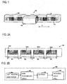
Fig. 1 is a view schematically showing an encoder according to first to third embodiments of the invention; -
Fig. 2A is a view showing a detection head shown inFig. 1 ; -
Fig. 2B is a block diagram of the detection head shown inFig. 1 ; -
Figs. 3A to 3C are views showing a relationship between light receiving array portions of the detection head and output signals; -
Fig. 4 is a diagram showing a case where contamination or the like is on a scale; -
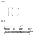
Fig. 5 is a view showing an example of a Lissajous waveform according to a third embodiment of the invention; -
Fig. 6 is a view showing an example of a scale according to a fourth embodiment of the invention; -
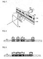
Fig. 7 is a view showing an example of a scale and the like according to a fifth embodiment of the invention; -
Fig. 8 is a view showing an example of a relationship between a scale and a light receiving array portions according to a sixth embodiment of the invention; -
Fig. 9 is a view showing an example of a relationship between a scale and a light receiving array portions according to a seventh embodiment of the invention; and -
Fig. 10 is a view showing an example of a relationship between a scale and a light receiving array portions according to an eighth embodiment of the invention. - Hereinafter, an exemplary embodiment of the invention will be described in detail with reference to the accompanying drawings.
- An encoder of a first embodiment of the invention will be described with reference to
Figs. 1 to 4 .Fig. 1 schematically shows theencoder 100 of the embodiment,Fig. 2A shows arrangement of light receiving array portions PDi (in the figure, i = 1 to 4) in a surface of adetection head 120 which is opposed to atrack 112,Fig. 2B is a block diagram of thedetection head 120,Fig. 3A shows arrangement ofoptical gratings 114 constituting thetrack 112,Fig. 3B shows light receiving array portions PDi, PDi+1 opposed to thetrack 112,Fig. 3C shows signal strengths (each indicated by a solid circle) which are output from individual light receiving elements constituting the light receiving array portions PDi, PDi+1, and a curve SW which is obtained by using the sinusoidal curve fitting, and the like, andFig. 4 is a diagram showing relationships between the scale and the light receiving array portions in the case where contamination or the like is on the scale. - First, the configuration of the
encoder 100 of the embodiment will be described. - The
encoder 100 is a linear encoder, and, as shown inFig. 1 , includes thescale 110, and thedetection head 120 which is relatively displaceable with respect to thescale 110. - In the
scale 110, as shown inFig. 1 , thetrack 112 which extends in the X direction (the direction along which the head is relatively displaceable) is disposed. Thetrack 112 is configured by theoptical gratings 114 which are arranged in the X direction at constant intervals (the track is an INC track in which an INC pattern is formed). Light is reflected from portions where theoptical gratings 114 are formed (Figs.3A,3C ). - As shown in
Fig. 1 , thedetection head 120 is placed while being opposed non-contactly to thetrack 112 of thescale 110. Thedetection head 120 includes: a light source (not shown); a lens (not shown); and the light receiving array portions PDi (i = 1 to 4) (detection array portions) which, as shown inFigs. 2A , are arranged in the X direction in the surface opposed to thetrack 112. The components are arranged so that light emitted from the light source is reflected by theoptical gratings 114 of thetrack 112 and then detected by the plurality of light receiving array portions PDi through the lens. - The light receiving array portions PDi have respective array widths Wi (i = 1 to 4), and intervals T are formed between the portions (in the embodiment, the intervals T are constant, but may be different from one another). Each of the light receiving array portions PDi is configured by a plurality of light receiving elements which are arranged in the X direction. In the embodiment, the widths of all the light receiving elements in the X direction are equal to one another, and the numbers of light receiving elements constituting the respective light receiving array portions PDi are equal to one another. Therefore, all the array widths Wi are made equal to one another.
- As shown in
Fig. 2B , thedetection head 120 includes, in addition to the light receiving array portions PDi, a noise filter/amplifier circuit 124, an A/D circuit 126, and aprocessing circuit 128. - The noise filter/
amplifier circuit 124 removes noises of signals output from the light receiving array portions PDi, and then amplifies and outputs the signals. - The A/
D circuit 126 converts the analog output signal which is output from the noise filter/amplifier circuit 124, to a digital signal. - The
processing circuit 128 calculates the position signal xi indicating the position x of thedetection head 120, for each of the light receiving array portions PDi from the digital signal (the output signal output from the light receiving array portion PDi) (in principle, all the position signals xi indicate the same position). Then, theprocessing circuit 128 combines the plural (four) obtained position signals xi with one another, and determines the position x of thedetection head 120 with respect to thescale 110. In order to determine the position x of thedetection head 120, a coefficient Ri (referred to as a reliability coefficient) indicated in Expression (1) is introduced. The reliability coefficient Ri performs weighting according to the level of the output signal output from each of the light receiving array portions PDi, on the position signal xi of the light receiving array portion PDi. The position x of thedetection head 120 is obtained from the average of the weighted position signals xi. In the embodiment, the symbol N indicates the number (4) of the light receiving array portions PDi. -

- In the embodiment, the reliability coefficient Ri is obtained from Expression (2). Namely, the signal intensity (output signal) of the j-th light receiving element in the light receiving array portion PDi is indicated by Yi,j, and the number of data obtained in the light receiving array portion PDi is indicated by ni (i = 1 to 4). As shown in the left view of
Fig. 3C , the absolute value (= |Yi,j - Yi,j+1|) of the difference between adjacent data is obtained from data of the signal intensities Yi,j of output signals output from individual light receiving elements constituting the light receiving array portion PDi. When the total sum of the values in the light receiving array portion PDi is obtained, the reliability coefficient Ri is obtained. This means that, when the contrast of a one-dimensional image of thetrack 112 obtained by the light receiving array portion PDi is large, the reliability coefficient Ri is large, or in other words the reliability is high. -

- Next, the operation of the
encoder 100 of the embodiment will be described. - Light emitted from the light source of the
detection head 120 impinges on thescale 110. Then, the light is reflected by theoptical gratings 114 of thescale 110, and incident on the light receiving elements of the light receiving array portions PDi of thedetection head 120. The light receiving array portions PDi perform an output operation corresponding to the intensities of light incident on the light receiving elements. The outputs of the portions are supplied to theprocessing circuit 128 through the noise filter/amplifier circuit 124 and the A/D circuit 126. - The
processing circuit 128 calculates the position signal xi indicating the position x of thedetection head 120, for each of the light receiving array portions PDi. By using the relationships of Expressions (1) and (2), then, the plural (four) obtained position signals xi are combined with one another, and the position x of thedetection head 120 with respect to thescale 110 is determined. - In the embodiment, in order to determine the position of the
detection head 120, as described above, the reliability coefficient Ri is introduced, thereby allowing the contribution rate in the combining of the position signals xi obtained from each light receiving array portion PDi, to be controlled. Schematically, when the array widths of the light receiving array portions PD1 and PD2 are equal to each other (W1 = W2) as shown inFig. 4 , the reliability coefficient R2 of the light receiving array portion PD2 to which dirt Stn adheres is smaller than the reliability coefficient R1 of the light receiving array portion PD1 (incidentally, when dirt does not adhere to both the opposing surfaces of the light receiving array portions PD1, PD3 of thescale 110 and the array width W3 is shorter than the array width W1, the reliability coefficient R3 is lower than the reliability coefficient R1 as shown inFig. 4 ). In the combining of the position signals, namely, the contribution rate of a position signal xi having a low reliability is lowered, and that of a position signal xi having a high reliability is increased, whereby the position signals xi are efficiently combined with each other. In other words, even in a state where contamination or the like adheres to thescale 110, the detection accuracy of the obtained position x of thedetection head 120 can be suppressed from being reduced, and the accuracy (reliability) of the position x can be improved. - In the embodiment, when the contrast of a one-dimensional image of the
track 112 obtained by the light receiving array portions PDi is large, therefore, it is determined that the reliability is high, and the reliability coefficient Ri is introduced. At this time, the reliability coefficient Ri is indicated by a simple computational expression as shown in Expression (2), and hence the calculation is simple and does not require a large storage capacity, so that the calculation can be realized in a short processing time and at a low cost. Even when the reliability coefficient Ri is indicated by the total sum of square values of differences of adjacent signal intensity data for each detection array portion PDi as indicated by Expression (3), similar effects are attained. -

- In the embodiment, moreover, the position x of the
detection head 120 is obtained from the weighted average of the position signals xi. Basically, only the contribution rate of each position signal xi obtained from the light receiving array portion PDi is changed, and an operation of daringly eliminating a specific position signal xi is not performed. In the embodiment, therefore, it is not required that, as in the prior art, the detection head is elongated in the direction (X direction) along which the head is relatively displaceable so that a larger number of light receiving array portions PDi are disposed. Consequently, thedetection head 120 can be maintained compact. - In the embodiment, the above-described weighted average is used. Therefore, the contribution rate of the position signal xi from the light receiving array portion PDi related to a region where dirt adheres to the
scale 110 is changed only in relative relationships with respect to the output signal from another light receiving array portion PDi. When all the light receiving array portions PDi are related to the region to which dirt adheres, namely, a large difference is not produced between the contribution rates of the position signals xi. In the embodiment, when the position x of thedetection head 120 is to be obtained, therefore, there is no case where the position signal xi based on the output signal is eliminated, and an error stop can be avoided from being caused in a controlling machine to which theencoder 100 is attached. - Usually, a controlling machine to which an encoder is attached requests the encoder to output the position x of a detection head at constant intervals. In the related art, when, in a scale, different signal processing times are used in a region to which contamination or the like adheres, and another region to which contamination or the like does not adhere, therefore, there is a possibility that a disadvantage such as a malfunction in the positioning of the controlling machine may be caused in the control. In the embodiment, by contrast, the process indicated by Expressions (1) and (2) (or (1) and (3)) is performed on the
scale 110 and in a region to which contamination or the like adheres, and another region to which contamination or the like does not adhere. In the embodiment, namely, the signal processing load is constant, and the signal processing time for obtaining the position x of thedetection head 120 is uniformalized. In the embodiment, therefore, it is possible to easily avoid the disadvantage in the positioning control of the controlling machine. - According to the embodiment, even when contamination or the like adheres to the
scale 110, the detection accuracy can be suppressed from being reduced, thedetection head 120 can be maintained compact, and an error stop can be avoided from being caused in a controlling machine to which theencoder 100 is attached. - Although the invention has been described by exemplifying the first embodiment, the invention is not limited to the first embodiment. It is a matter of course that improvements and design changes can be made without departing the spirit of the invention.
- In the first embodiment, for example, the
processing circuit 128 uses the function indicated by Expression (2) as the reliability coefficient Ri. The invention is not limited to this. For example, the invention may be configured as a second embodiment which will be described below. In the embodiment, the function indicated by Expression (4) is used as the reliability coefficient Ri. As shown in the right view ofFig. 3C , the sinusoidal curve fitting SW is performed on data of signal strengths of the output signals which are output from individual light receiving elements constituting the light receiving array portions PDi, and the product of the amplitude Amp of the sinusoidal wave obtained by the fitting, and the array width Wi of the detection array portion PDi is used as the reliability coefficient Ri. -

- In the embodiment, when the amplitude Amp obtained in the fitting is large and the array width Wi is large, as described above, the reliability of the position signal xi is made high, and the reliability coefficient Ri is introduced. Even when an error occurs in the output signal, namely, the error can be averaged by performing the process called fitting, and therefore the
detection head 120 can be accurately positioned. - Alternatively, the invention may be configured as a third embodiment which will be described below. In the embodiment, Expression (5) is used as the reliability coefficient Ri. In the embodiment, a conventional two-phase sinusoidal signal is used as the output signal obtained in the
processing circuit 128. In the light receiving array portion PDi, light receiving elements are arranged so as to produce outputs which are different in phase by 90 degrees from each other. Then, the product of the array width Wi of the light receiving array portion PDi, and the diameter ri of a Lissajous waveform Lsj ofFig. 5 which is obtained from the two-phase sinusoidal signal that is an output signal output from the light receiving array portion PDi is set as the reliability coefficient Ri. -

- In the embodiment, therefore, the reliability of the position signal xi is high when the diameter ri of the Lissajous waveform Lsj is large and the array width Wi is large, and hence the same effects as those in the above-described embodiments are attained. In the embodiment, moreover, the Lissajous waveform Lsj is used in the same manner as the prior art, and hence the change of the of the process contents of the
processing circuit 128 can be made minimum, so that particularly the development period can be shortened. - In the above-described embodiments, the invention is applied to an INC pattern in which optical gratings are arranged at regular intervals. The invention is not limited to this. The invention particularly exerts the effects in the case where a periodical output signal can be obtained from the light receiving array portions PDi such as the case where the invention is applied to the INC pattern of the
scale 110, or namely the case where a track on a scale has optical gratings which are arranged at constant intervals (the track has an INC component). Therefore, any of the relationships indicated by Expressions (2) to (5) can be applied to anintegrated pattern 213 which is shown in a fourth embodiment shown inFig. 6 , and which is configured by an ABS pattern based on a pseudorandom code, and an INC pattern (Fig. 6 ofJP-A-2009-2702 scale 210 shown inFig. 6 is formed by anintegrated pattern 213 and anINC pattern 212.
The invention may be applied not only to a reflection type encoder which is shown in the embodiments, but also to a transmission type encoder such as shown inFig. 7 . The transmission type encoder shown inFig. 7 includes alight source 302, ascale 310 on which anINC pattern 312 and anintegrated pattern 313 are formed, alens 304 and adetection head 320. - In the embodiments, the array widths Wi of the light receiving array portions PDi are equal to one another, and the intervals T of the light receiving array portions are equal to one another. The invention is not limited to this. As in a sixth embodiment shown in
Fig. 8 , for example, the array widths Wi may be different from one another, or the intervals may be different from one another. As in a seventh embodiment shown inFig. 9 , moreover, a plurality of light receiving array portions PDi may be disposed by dividing a large light receiving array which is integrally continuous, without forming gaps between the portions. InFig. 8 and Fig. 9 , thereference numbers - In the embodiments, one scale is placed for one detection head. The invention is not limited to this. As in an eighth embodiment shown in
Fig. 10 , for example, twoscales 610A, 610B may be used as measurement objects. In this case, the position x of the detection head is obtained from each of thescales 610A, 610B, and therefore yawing correction or the like may be performed on the detection head depending on the difference of the two positions. - The embodiments have been described by using the photoelectric (linear) encoder including the linearly-shaped scale. The invention is not limited to this. For example, the encoder must be configured so that the detection head has a plurality of detection array portions including a plurality of detection elements. Therefore, a capacitance type encoder or an electromagnetic induction type encoder may be used. Similarly, the scale is not limited to be linear, and the invention may be applied to a rotary encoder in which a scale has a disk-like shape, and a track is disposed in the circumferential direction of the scale.
- According to the encoder of the invention, the detection head can be maintained compact, and occurrences of an error stop can be reduced in a controlling machine to which the encoder is attached. Therefore, the invention can be widely applied not only to a photoelectric encoder, but also to capacitance type and electromagnetic induction type linear encoders, and a rotary encoder.
Claims (4)
- An encoder comprising:a scale; anda detection head which is relatively displaceable with respect to the scale,
wherein the detection head includes
a plurality of detection array portions that are arranged in a direction along which the detection head is relatively displaceable,
a processor configured to calculate position signals indicating a position of the detection head from output signals output from the detection array portions, and to combine the position signals with one another and determine the position of the detection head with respect to the scale, and
wherein the processor is configured to perform weighting according to a level of the output signal on the position signal of each of the detection array portions, and to average the weighted position signals. - The encoder according to claim 1, wherein
the weighting on the position signal is performed by setting a total sum of absolute values of differences of adjacent ones of signal strength data of the output signals output from individual detection elements constituting the detection array portions, or square values of the differences, as a coefficient of the position signal. - The encoder according to claim 1, wherein
the weighting on the position signal is performed by performing sinusoidal curve fitting on signal strength data of the output signals output from individual detection elements constituting the detection array portions, and setting a product of an amplitude of a sinusoidal wave obtained by the fitting, and an array width of the detection array portions, as a coefficient of the position signal. - An encoder according to claim 1, wherein
the weighting on the position signal is performed by setting a product of a diameter of a Lissajous waveform obtained from a two-phase sinusoidal signal which is the output signal, and an array width of the detection array portions, as a coefficient of the position signal.
Applications Claiming Priority (1)
| Application Number | Priority Date | Filing Date | Title |
|---|---|---|---|
| JP2010228310A JP5616741B2 (en) | 2010-10-08 | 2010-10-08 | Encoder |
Publications (2)
| Publication Number | Publication Date |
|---|---|
| EP2439498A1 true EP2439498A1 (en) | 2012-04-11 |
| EP2439498B1 EP2439498B1 (en) | 2017-08-23 |
Family
ID=44905464
Family Applications (1)
| Application Number | Title | Priority Date | Filing Date |
|---|---|---|---|
| EP11184271.2A Active EP2439498B1 (en) | 2010-10-08 | 2011-10-07 | Encoder |
Country Status (3)
| Country | Link |
|---|---|
| US (1) | US8729458B2 (en) |
| EP (1) | EP2439498B1 (en) |
| JP (1) | JP5616741B2 (en) |
Cited By (1)
| Publication number | Priority date | Publication date | Assignee | Title |
|---|---|---|---|---|
| US10670431B2 (en) | 2015-09-09 | 2020-06-02 | Renishaw Plc | Encoder apparatus that includes a scale and a readhead that are movable relative to each other configured to reduce the adverse effect of undesirable frequencies in the scale signal to reduce the encoder sub-divisional error |
Families Citing this family (9)
| Publication number | Priority date | Publication date | Assignee | Title |
|---|---|---|---|---|
| JP5616741B2 (en) * | 2010-10-08 | 2014-10-29 | 株式会社ミツトヨ | Encoder |
| JP5829464B2 (en) * | 2011-09-01 | 2015-12-09 | 株式会社ミツトヨ | Absolute length encoder |
| JP5877212B2 (en) | 2014-01-10 | 2016-03-02 | キヤノンプレシジョン株式会社 | Encoder, device using encoder, and encoder calculation program |
| JP6355349B2 (en) * | 2014-02-04 | 2018-07-11 | 株式会社ミツトヨ | Linear encoder |
| JP6359340B2 (en) * | 2014-05-27 | 2018-07-18 | 株式会社ミツトヨ | Scale and optical encoder |
| DE102015216268A1 (en) * | 2015-08-26 | 2017-03-02 | Dr. Johannes Heidenhain Gmbh | Optical position measuring device |
| US10551223B2 (en) * | 2017-03-20 | 2020-02-04 | Tt Electronics Plc | Method and apparatus for configurable photodetector array patterning for optical encoders |
| US11378422B2 (en) | 2018-11-05 | 2022-07-05 | Tt Electronics Plc | Method and apparatus for improved performance in encoder systems by configuring a detector array using a partition map and assigning weights to output currents of the detector array |
| DE102021118091A1 (en) | 2021-07-13 | 2023-01-19 | Neura Robotics GmbH | Encoder system and method for determining the reading head position in an encoder system |
Citations (5)
| Publication number | Priority date | Publication date | Assignee | Title |
|---|---|---|---|---|
| EP0302194A2 (en) * | 1987-08-07 | 1989-02-08 | Dr. Johannes Heidenhain GmbH | Position-measuring device with plural probe placings |
| EP0789226A1 (en) * | 1996-02-10 | 1997-08-13 | Dr. Johannes Heidenhain GmbH | Position measuring device |
| JP2003065803A (en) | 2001-08-28 | 2003-03-05 | Mitsutoyo Corp | Photoelectric encoder |
| EP1821075A2 (en) * | 2006-02-15 | 2007-08-22 | Mitutoyo Corporation | Photoelectric encoder |
| EP2006642A2 (en) * | 2007-06-19 | 2008-12-24 | Mitutoyo Corporation | Absolute position encoder |
Family Cites Families (20)
| Publication number | Priority date | Publication date | Assignee | Title |
|---|---|---|---|---|
| US4445110A (en) * | 1980-07-28 | 1984-04-24 | Itek Corporation | Absolute optical encoder system |
| US4360730A (en) * | 1980-10-16 | 1982-11-23 | Itek Corporation | Encoder alignment method and apparatus |
| US4465928A (en) * | 1981-08-17 | 1984-08-14 | Itek Corporation | Optically multiplexed encoder system |
| US4786891A (en) * | 1986-04-08 | 1988-11-22 | Yokogawa Electric Corporation | Absolute encoder for linear or angular position measurements |
| US5267012A (en) * | 1989-04-27 | 1993-11-30 | Coherent, Inc. | Apparatus for measuring the mode quality of a laser beam |
| US5502311A (en) * | 1992-01-17 | 1996-03-26 | Nikon Corporation | Method of and apparatus for detecting plane position |
| DE19530386A1 (en) * | 1995-08-18 | 1997-02-20 | Philips Patentverwaltung | Position sensor |
| JP3220955B2 (en) * | 1996-05-31 | 2001-10-22 | 株式会社東京精密 | Non-contact surface shape measuring method and device |
| JP3551252B2 (en) * | 1998-07-23 | 2004-08-04 | 株式会社安川電機 | Absolute encoder |
| AUPP777898A0 (en) * | 1998-12-17 | 1999-01-21 | Bishop Innovation Pty Limited | Position sensor |
| US7312437B2 (en) * | 2002-07-02 | 2007-12-25 | Olympus Corporation | Displacement sensor, method for detecting the optimal reference position, and method for judging stability of detecting the reference position of displacement sensor |
| US7268341B2 (en) * | 2004-05-21 | 2007-09-11 | Silicon Light Machines Corporation | Optical position sensing device including interlaced groups of photosensitive elements |
| US20050258346A1 (en) * | 2004-05-21 | 2005-11-24 | Silicon Light Machines Corporation | Optical positioning device resistant to speckle fading |
| WO2006002311A2 (en) * | 2004-06-23 | 2006-01-05 | Fe Technical Services, Inc. | Capacitive sensing techniques |
| US7138620B2 (en) * | 2004-10-29 | 2006-11-21 | Silicon Light Machines Corporation | Two-dimensional motion sensor |
| NL1036351A1 (en) * | 2007-12-31 | 2009-07-01 | Asml Netherlands Bv | Alignment system and alignment marks for use therewith cross-reference to related applications. |
| JP5112989B2 (en) * | 2008-08-20 | 2013-01-09 | 株式会社ミツトヨ | Photoelectric encoder |
| US8063355B2 (en) * | 2009-01-08 | 2011-11-22 | Avago Technologies Limited | Reflective multi-turn encoders with different light sensing systems |
| JP5439163B2 (en) * | 2009-12-25 | 2014-03-12 | オリンパス株式会社 | Signal processing device for optical signal output device and optical displacement detection device |
| JP5616741B2 (en) * | 2010-10-08 | 2014-10-29 | 株式会社ミツトヨ | Encoder |
-
2010
- 2010-10-08 JP JP2010228310A patent/JP5616741B2/en active Active
-
2011
- 2011-10-05 US US13/253,267 patent/US8729458B2/en active Active
- 2011-10-07 EP EP11184271.2A patent/EP2439498B1/en active Active
Patent Citations (7)
| Publication number | Priority date | Publication date | Assignee | Title |
|---|---|---|---|---|
| EP0302194A2 (en) * | 1987-08-07 | 1989-02-08 | Dr. Johannes Heidenhain GmbH | Position-measuring device with plural probe placings |
| EP0789226A1 (en) * | 1996-02-10 | 1997-08-13 | Dr. Johannes Heidenhain GmbH | Position measuring device |
| JPH09229717A (en) | 1996-02-10 | 1997-09-05 | Dr Johannes Heidenhain Gmbh | Position-measuring apparatus |
| JP2003065803A (en) | 2001-08-28 | 2003-03-05 | Mitsutoyo Corp | Photoelectric encoder |
| EP1821075A2 (en) * | 2006-02-15 | 2007-08-22 | Mitutoyo Corporation | Photoelectric encoder |
| EP2006642A2 (en) * | 2007-06-19 | 2008-12-24 | Mitutoyo Corporation | Absolute position encoder |
| JP2009002702A (en) | 2007-06-19 | 2009-01-08 | Mitsutoyo Corp | Absolute position measuring encoder |
Cited By (1)
| Publication number | Priority date | Publication date | Assignee | Title |
|---|---|---|---|---|
| US10670431B2 (en) | 2015-09-09 | 2020-06-02 | Renishaw Plc | Encoder apparatus that includes a scale and a readhead that are movable relative to each other configured to reduce the adverse effect of undesirable frequencies in the scale signal to reduce the encoder sub-divisional error |
Also Published As
| Publication number | Publication date |
|---|---|
| JP5616741B2 (en) | 2014-10-29 |
| JP2012083153A (en) | 2012-04-26 |
| US20120085897A1 (en) | 2012-04-12 |
| US8729458B2 (en) | 2014-05-20 |
| EP2439498B1 (en) | 2017-08-23 |
Similar Documents
| Publication | Publication Date | Title |
|---|---|---|
| EP2439498B1 (en) | Encoder | |
| EP2365291B1 (en) | Photoelectric encoder | |
| EP2754999B1 (en) | Scale, displacement detection apparatus, lens apparatus, image pickup system, and assembling apparatus | |
| EP2511666B1 (en) | Encoder | |
| EP1821075B1 (en) | Photoelectric encoder | |
| EP2120019A2 (en) | Absolute position length measurement type encoder | |
| EP1980824A1 (en) | Absolute position length-measurement type encoder | |
| EP1903314B1 (en) | Origin detection method for optical encoder | |
| US11073410B2 (en) | Position measuring device | |
| US7994470B2 (en) | Photoelectric encoder | |
| EP2219012A2 (en) | Origin detection apparatus, displacement measurement apparatus and optical apparatus | |
| EP3035003A1 (en) | Position detection apparatus, lens apparatus, image pickup system, machine tool apparatus, position detection method, program, and storage medium | |
| EP2369304B1 (en) | Photoelectric encoder | |
| US9250057B2 (en) | Displacement detection apparatus | |
| US10190893B2 (en) | Encoder | |
| EP2908101B1 (en) | Encoder with origin detection | |
| EP2587226A2 (en) | Displacement detecting device and method | |
| JP6440609B2 (en) | Position detection device, lens device, imaging system, machine tool, exposure device, position detection method, program, storage medium | |
| US11079223B2 (en) | Absolute rotary encoder and apparatus | |
| EP2650654A1 (en) | Encoder | |
| EP2778626B1 (en) | Position detection apparatus, lens apparatus, image pickup system, machine tool apparatus, position detection method, program, and storage medium | |
| EP2733469B1 (en) | Measurement apparatus, measurement method, and absolute encoder | |
| WO2014132631A1 (en) | Absolute encoder | |
| JP4783698B2 (en) | Electromagnetic induction encoder | |
| JP6196539B2 (en) | Optical encoder |
Legal Events
| Date | Code | Title | Description |
|---|---|---|---|
| AK | Designated contracting states |
Kind code of ref document: A1 Designated state(s): AL AT BE BG CH CY CZ DE DK EE ES FI FR GB GR HR HU IE IS IT LI LT LU LV MC MK MT NL NO PL PT RO RS SE SI SK SM TR |
|
| AX | Request for extension of the european patent |
Extension state: BA ME |
|
| PUAI | Public reference made under article 153(3) epc to a published international application that has entered the european phase |
Free format text: ORIGINAL CODE: 0009012 |
|
| 17P | Request for examination filed |
Effective date: 20121011 |
|
| GRAP | Despatch of communication of intention to grant a patent |
Free format text: ORIGINAL CODE: EPIDOSNIGR1 |
|
| RIN1 | Information on inventor provided before grant (corrected) |
Inventor name: KATO, YOSHIAKI |
|
| INTG | Intention to grant announced |
Effective date: 20170323 |
|
| RAP1 | Party data changed (applicant data changed or rights of an application transferred) |
Owner name: MITUTOYO CORPORATION |
|
| GRAS | Grant fee paid |
Free format text: ORIGINAL CODE: EPIDOSNIGR3 |
|
| GRAA | (expected) grant |
Free format text: ORIGINAL CODE: 0009210 |
|
| AK | Designated contracting states |
Kind code of ref document: B1 Designated state(s): AL AT BE BG CH CY CZ DE DK EE ES FI FR GB GR HR HU IE IS IT LI LT LU LV MC MK MT NL NO PL PT RO RS SE SI SK SM TR |
|
| REG | Reference to a national code |
Ref country code: GB Ref legal event code: FG4D |
|
| REG | Reference to a national code |
Ref country code: CH Ref legal event code: EP |
|
| REG | Reference to a national code |
Ref country code: AT Ref legal event code: REF Ref document number: 921832 Country of ref document: AT Kind code of ref document: T Effective date: 20170915 |
|
| REG | Reference to a national code |
Ref country code: IE Ref legal event code: FG4D |
|
| REG | Reference to a national code |
Ref country code: DE Ref legal event code: R096 Ref document number: 602011040794 Country of ref document: DE |
|
| REG | Reference to a national code |
Ref country code: NL Ref legal event code: MP Effective date: 20170823 |
|
| REG | Reference to a national code |
Ref country code: LT Ref legal event code: MG4D |
|
| REG | Reference to a national code |
Ref country code: AT Ref legal event code: MK05 Ref document number: 921832 Country of ref document: AT Kind code of ref document: T Effective date: 20170823 |
|
| PG25 | Lapsed in a contracting state [announced via postgrant information from national office to epo] |
Ref country code: AT Free format text: LAPSE BECAUSE OF FAILURE TO SUBMIT A TRANSLATION OF THE DESCRIPTION OR TO PAY THE FEE WITHIN THE PRESCRIBED TIME-LIMIT Effective date: 20170823 Ref country code: NL Free format text: LAPSE BECAUSE OF FAILURE TO SUBMIT A TRANSLATION OF THE DESCRIPTION OR TO PAY THE FEE WITHIN THE PRESCRIBED TIME-LIMIT Effective date: 20170823 Ref country code: FI Free format text: LAPSE BECAUSE OF FAILURE TO SUBMIT A TRANSLATION OF THE DESCRIPTION OR TO PAY THE FEE WITHIN THE PRESCRIBED TIME-LIMIT Effective date: 20170823 Ref country code: NO Free format text: LAPSE BECAUSE OF FAILURE TO SUBMIT A TRANSLATION OF THE DESCRIPTION OR TO PAY THE FEE WITHIN THE PRESCRIBED TIME-LIMIT Effective date: 20171123 Ref country code: SE Free format text: LAPSE BECAUSE OF FAILURE TO SUBMIT A TRANSLATION OF THE DESCRIPTION OR TO PAY THE FEE WITHIN THE PRESCRIBED TIME-LIMIT Effective date: 20170823 Ref country code: HR Free format text: LAPSE BECAUSE OF FAILURE TO SUBMIT A TRANSLATION OF THE DESCRIPTION OR TO PAY THE FEE WITHIN THE PRESCRIBED TIME-LIMIT Effective date: 20170823 Ref country code: LT Free format text: LAPSE BECAUSE OF FAILURE TO SUBMIT A TRANSLATION OF THE DESCRIPTION OR TO PAY THE FEE WITHIN THE PRESCRIBED TIME-LIMIT Effective date: 20170823 |
|
| PG25 | Lapsed in a contracting state [announced via postgrant information from national office to epo] |
Ref country code: PL Free format text: LAPSE BECAUSE OF FAILURE TO SUBMIT A TRANSLATION OF THE DESCRIPTION OR TO PAY THE FEE WITHIN THE PRESCRIBED TIME-LIMIT Effective date: 20170823 Ref country code: BG Free format text: LAPSE BECAUSE OF FAILURE TO SUBMIT A TRANSLATION OF THE DESCRIPTION OR TO PAY THE FEE WITHIN THE PRESCRIBED TIME-LIMIT Effective date: 20171123 Ref country code: RS Free format text: LAPSE BECAUSE OF FAILURE TO SUBMIT A TRANSLATION OF THE DESCRIPTION OR TO PAY THE FEE WITHIN THE PRESCRIBED TIME-LIMIT Effective date: 20170823 Ref country code: LV Free format text: LAPSE BECAUSE OF FAILURE TO SUBMIT A TRANSLATION OF THE DESCRIPTION OR TO PAY THE FEE WITHIN THE PRESCRIBED TIME-LIMIT Effective date: 20170823 Ref country code: GR Free format text: LAPSE BECAUSE OF FAILURE TO SUBMIT A TRANSLATION OF THE DESCRIPTION OR TO PAY THE FEE WITHIN THE PRESCRIBED TIME-LIMIT Effective date: 20171124 Ref country code: IS Free format text: LAPSE BECAUSE OF FAILURE TO SUBMIT A TRANSLATION OF THE DESCRIPTION OR TO PAY THE FEE WITHIN THE PRESCRIBED TIME-LIMIT Effective date: 20171223 Ref country code: ES Free format text: LAPSE BECAUSE OF FAILURE TO SUBMIT A TRANSLATION OF THE DESCRIPTION OR TO PAY THE FEE WITHIN THE PRESCRIBED TIME-LIMIT Effective date: 20170823 |
|
| PG25 | Lapsed in a contracting state [announced via postgrant information from national office to epo] |
Ref country code: DK Free format text: LAPSE BECAUSE OF FAILURE TO SUBMIT A TRANSLATION OF THE DESCRIPTION OR TO PAY THE FEE WITHIN THE PRESCRIBED TIME-LIMIT Effective date: 20170823 Ref country code: CZ Free format text: LAPSE BECAUSE OF FAILURE TO SUBMIT A TRANSLATION OF THE DESCRIPTION OR TO PAY THE FEE WITHIN THE PRESCRIBED TIME-LIMIT Effective date: 20170823 Ref country code: RO Free format text: LAPSE BECAUSE OF FAILURE TO SUBMIT A TRANSLATION OF THE DESCRIPTION OR TO PAY THE FEE WITHIN THE PRESCRIBED TIME-LIMIT Effective date: 20170823 |
|
| REG | Reference to a national code |
Ref country code: DE Ref legal event code: R097 Ref document number: 602011040794 Country of ref document: DE |
|
| PG25 | Lapsed in a contracting state [announced via postgrant information from national office to epo] |
Ref country code: MC Free format text: LAPSE BECAUSE OF FAILURE TO SUBMIT A TRANSLATION OF THE DESCRIPTION OR TO PAY THE FEE WITHIN THE PRESCRIBED TIME-LIMIT Effective date: 20170823 Ref country code: SK Free format text: LAPSE BECAUSE OF FAILURE TO SUBMIT A TRANSLATION OF THE DESCRIPTION OR TO PAY THE FEE WITHIN THE PRESCRIBED TIME-LIMIT Effective date: 20170823 Ref country code: SM Free format text: LAPSE BECAUSE OF FAILURE TO SUBMIT A TRANSLATION OF THE DESCRIPTION OR TO PAY THE FEE WITHIN THE PRESCRIBED TIME-LIMIT Effective date: 20170823 Ref country code: EE Free format text: LAPSE BECAUSE OF FAILURE TO SUBMIT A TRANSLATION OF THE DESCRIPTION OR TO PAY THE FEE WITHIN THE PRESCRIBED TIME-LIMIT Effective date: 20170823 Ref country code: IT Free format text: LAPSE BECAUSE OF FAILURE TO SUBMIT A TRANSLATION OF THE DESCRIPTION OR TO PAY THE FEE WITHIN THE PRESCRIBED TIME-LIMIT Effective date: 20170823 |
|
| REG | Reference to a national code |
Ref country code: CH Ref legal event code: PL |
|
| PLBE | No opposition filed within time limit |
Free format text: ORIGINAL CODE: 0009261 |
|
| STAA | Information on the status of an ep patent application or granted ep patent |
Free format text: STATUS: NO OPPOSITION FILED WITHIN TIME LIMIT |
|
| REG | Reference to a national code |
Ref country code: IE Ref legal event code: MM4A |
|
| REG | Reference to a national code |
Ref country code: FR Ref legal event code: ST Effective date: 20180629 |
|
| PG25 | Lapsed in a contracting state [announced via postgrant information from national office to epo] |
Ref country code: LU Free format text: LAPSE BECAUSE OF NON-PAYMENT OF DUE FEES Effective date: 20171007 Ref country code: LI Free format text: LAPSE BECAUSE OF NON-PAYMENT OF DUE FEES Effective date: 20171031 Ref country code: CH Free format text: LAPSE BECAUSE OF NON-PAYMENT OF DUE FEES Effective date: 20171031 |
|
| 26N | No opposition filed |
Effective date: 20180524 |
|
| REG | Reference to a national code |
Ref country code: BE Ref legal event code: MM Effective date: 20171031 |
|
| PG25 | Lapsed in a contracting state [announced via postgrant information from national office to epo] |
Ref country code: FR Free format text: LAPSE BECAUSE OF NON-PAYMENT OF DUE FEES Effective date: 20171031 Ref country code: BE Free format text: LAPSE BECAUSE OF NON-PAYMENT OF DUE FEES Effective date: 20171031 Ref country code: SI Free format text: LAPSE BECAUSE OF FAILURE TO SUBMIT A TRANSLATION OF THE DESCRIPTION OR TO PAY THE FEE WITHIN THE PRESCRIBED TIME-LIMIT Effective date: 20170823 |
|
| PG25 | Lapsed in a contracting state [announced via postgrant information from national office to epo] |
Ref country code: MT Free format text: LAPSE BECAUSE OF NON-PAYMENT OF DUE FEES Effective date: 20171007 |
|
| PG25 | Lapsed in a contracting state [announced via postgrant information from national office to epo] |
Ref country code: IE Free format text: LAPSE BECAUSE OF NON-PAYMENT OF DUE FEES Effective date: 20171007 |
|
| PG25 | Lapsed in a contracting state [announced via postgrant information from national office to epo] |
Ref country code: HU Free format text: LAPSE BECAUSE OF FAILURE TO SUBMIT A TRANSLATION OF THE DESCRIPTION OR TO PAY THE FEE WITHIN THE PRESCRIBED TIME-LIMIT; INVALID AB INITIO Effective date: 20111007 |
|
| PG25 | Lapsed in a contracting state [announced via postgrant information from national office to epo] |
Ref country code: CY Free format text: LAPSE BECAUSE OF NON-PAYMENT OF DUE FEES Effective date: 20170823 |
|
| PG25 | Lapsed in a contracting state [announced via postgrant information from national office to epo] |
Ref country code: MK Free format text: LAPSE BECAUSE OF FAILURE TO SUBMIT A TRANSLATION OF THE DESCRIPTION OR TO PAY THE FEE WITHIN THE PRESCRIBED TIME-LIMIT Effective date: 20170823 |
|
| PG25 | Lapsed in a contracting state [announced via postgrant information from national office to epo] |
Ref country code: TR Free format text: LAPSE BECAUSE OF FAILURE TO SUBMIT A TRANSLATION OF THE DESCRIPTION OR TO PAY THE FEE WITHIN THE PRESCRIBED TIME-LIMIT Effective date: 20170823 |
|
| PG25 | Lapsed in a contracting state [announced via postgrant information from national office to epo] |
Ref country code: PT Free format text: LAPSE BECAUSE OF FAILURE TO SUBMIT A TRANSLATION OF THE DESCRIPTION OR TO PAY THE FEE WITHIN THE PRESCRIBED TIME-LIMIT Effective date: 20170823 |
|
| PG25 | Lapsed in a contracting state [announced via postgrant information from national office to epo] |
Ref country code: AL Free format text: LAPSE BECAUSE OF FAILURE TO SUBMIT A TRANSLATION OF THE DESCRIPTION OR TO PAY THE FEE WITHIN THE PRESCRIBED TIME-LIMIT Effective date: 20170823 |
|
| PGFP | Annual fee paid to national office [announced via postgrant information from national office to epo] |
Ref country code: DE Payment date: 20251021 Year of fee payment: 15 |
|
| PGFP | Annual fee paid to national office [announced via postgrant information from national office to epo] |
Ref country code: GB Payment date: 20251022 Year of fee payment: 15 |