EP2439491A1 - Distance measuring device and distance measuring method - Google Patents
Distance measuring device and distance measuring method Download PDFInfo
- Publication number
- EP2439491A1 EP2439491A1 EP10783102A EP10783102A EP2439491A1 EP 2439491 A1 EP2439491 A1 EP 2439491A1 EP 10783102 A EP10783102 A EP 10783102A EP 10783102 A EP10783102 A EP 10783102A EP 2439491 A1 EP2439491 A1 EP 2439491A1
- Authority
- EP
- European Patent Office
- Prior art keywords
- region
- relative error
- regions
- image size
- distance
- Prior art date
- Legal status (The legal status is an assumption and is not a legal conclusion. Google has not performed a legal analysis and makes no representation as to the accuracy of the status listed.)
- Withdrawn
Links
Images


Classifications
-
- G—PHYSICS
- G01—MEASURING; TESTING
- G01C—MEASURING DISTANCES, LEVELS OR BEARINGS; SURVEYING; NAVIGATION; GYROSCOPIC INSTRUMENTS; PHOTOGRAMMETRY OR VIDEOGRAMMETRY
- G01C3/00—Measuring distances in line of sight; Optical rangefinders
- G01C3/02—Details
- G01C3/06—Use of electric means to obtain final indication
- G01C3/08—Use of electric radiation detectors
-
- G—PHYSICS
- G06—COMPUTING OR CALCULATING; COUNTING
- G06T—IMAGE DATA PROCESSING OR GENERATION, IN GENERAL
- G06T7/00—Image analysis
- G06T7/50—Depth or shape recovery
-
- G—PHYSICS
- G06—COMPUTING OR CALCULATING; COUNTING
- G06V—IMAGE OR VIDEO RECOGNITION OR UNDERSTANDING
- G06V20/00—Scenes; Scene-specific elements
- G06V20/50—Context or environment of the image
- G06V20/56—Context or environment of the image exterior to a vehicle by using sensors mounted on the vehicle
- G06V20/58—Recognition of moving objects or obstacles, e.g. vehicles or pedestrians; Recognition of traffic objects, e.g. traffic signs, traffic lights or roads
- G06V20/582—Recognition of moving objects or obstacles, e.g. vehicles or pedestrians; Recognition of traffic objects, e.g. traffic signs, traffic lights or roads of traffic signs
-
- G—PHYSICS
- G06—COMPUTING OR CALCULATING; COUNTING
- G06T—IMAGE DATA PROCESSING OR GENERATION, IN GENERAL
- G06T2207/00—Indexing scheme for image analysis or image enhancement
- G06T2207/10—Image acquisition modality
- G06T2207/10016—Video; Image sequence
-
- G—PHYSICS
- G06—COMPUTING OR CALCULATING; COUNTING
- G06T—IMAGE DATA PROCESSING OR GENERATION, IN GENERAL
- G06T2207/00—Indexing scheme for image analysis or image enhancement
- G06T2207/20—Special algorithmic details
- G06T2207/20076—Probabilistic image processing
-
- G—PHYSICS
- G06—COMPUTING OR CALCULATING; COUNTING
- G06T—IMAGE DATA PROCESSING OR GENERATION, IN GENERAL
- G06T2207/00—Indexing scheme for image analysis or image enhancement
- G06T2207/30—Subject of image; Context of image processing
- G06T2207/30248—Vehicle exterior or interior
- G06T2207/30252—Vehicle exterior; Vicinity of vehicle
- G06T2207/30256—Lane; Road marking
Definitions
- the present invention relates to a distance measuring apparatus and distance measuring method that measure a distance to an object using a photographic image.
- the distance between a camera and an object can be found by means of equation 1 below.
- O ⁇ b ⁇ j ⁇ e ⁇ c ⁇ t d ⁇ i ⁇ s ⁇ tan ⁇ c ⁇ e c ⁇ a ⁇ m ⁇ e ⁇ r ⁇ a f ⁇ o ⁇ c ⁇ a ⁇ l l ⁇ e ⁇ n ⁇ g ⁇ t ⁇ h ⁇ a ⁇ c ⁇ t ⁇ u ⁇ a ⁇ l o b ⁇ j ⁇ e ⁇ c ⁇ t s ⁇ i ⁇ z ⁇ e / p ⁇ i ⁇ x ⁇ e ⁇ l p ⁇ i ⁇ t ⁇ c ⁇ h ⁇ n u ⁇ m ⁇ b ⁇ e ⁇ r
- the actual object size is the actual size of an object
- the pixel pitch is the size of one pixel of an imaging element (CCD, CMOS, or the like)
- the number of object pixels is the number of pixels by which the object is displayed. That is to say, "pixel pitch ⁇ number of object pixels" represents the image size of an object.
- the focal length and pixel pitch are camera specification characteristics, and are normally fixed values or known values of a particular camera.
- Patent Literature 1 and 2 are examples of technologies that measure the distance between a camera and an object using the relationship in equation 1.
- the technology disclosed in Patent Literature 1 images road signs, traffic signals, or suchlike objects whose sizes have been unified according to a standard, and measures the distance to an object based on the size of an object in an image.
- Patent Literature 2 images a vehicle number plate, measures the size of characters on the number plate in the image, and measures the distance from the camera to the vehicle by comparing the size of the measured characters with the size of a known character decided according to a standard.
- Patent Literature 3 a position recording apparatus is disclosed whereby accurate position recording of an object can be performed by taking into account object detection error.
- a vehicle's own position is measured using a GPS or suchlike positioning apparatus, and when the relative positions (relative distance and relative direction) of an object and the vehicle are calculated from a photographic image, error occurs in measurement of the vehicle's own position or calculation of the relative positions. Consequently, a technology is disclosed whereby maximum error is compared for a plurality of points at which an object is detected, and position information of an object captured at a point at which maximum error is smallest is recorded.
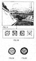
- FIG.1 shows an example in which a speed limit sign is detected from an actual vehicle-mounted camera image.
- FIG.1A is a vehicle-mounted camera image
- FIG.1B shows the results of detecting a speed limit sign from virtually consecutive frames, normalized to a 64 ⁇ 64 size.
- FIG.1B even if an actual distance of movement of a vehicle is small, there is great variation in the image size of detected images due to environmental variations such as changes in illumination and relative direction.
- One aspect of a distance measuring apparatus of the present invention employs a configuration having: a region image detection section that detects, from a captured image of an object, region images of a plurality of regions that are included in the object and whose sizes are known; a relative error comparison section that uses image sizes of the plurality of regions detected by the region image detection section, and information regarding sizes that are known in the plurality of regions, to select a region image size that minimizes relative error that is a ratio between the image size and error included in the image size; and a distance estimation section that uses the selected region image size to estimate the distance to the object.
- the present invention can sufficiently suppress degradation of distance detection accuracy due to object detection error, and measure the distance to an imaged object with a high degree of accuracy.
- FIG.2A is a drawing showing a speed limit sign.
- the circular outer frame of a sign is taken as a first region
- the circular inner frame is taken as a second region
- a rectangular frame surrounding left numeral "5" or right numeral "0" is defined as a third region.
- FIG.2B shows a binary image of FIG.2A .
- the speed limit sign shown in FIG.2 will be described as an example.
- FIG.3 is a block diagram showing the configuration of distance measuring apparatus 100 according to Embodiment 1 of the present invention.
- Distance measuring apparatus 100 is installed in an automobile or suchlike vehicle, and inputs image information (a binary image) to first through third region detection sections 101 through 103.
- Image information is an image of vehicle surroundings captured in real time by a camera installed in a vehicle.
- First through third region detection sections 101 through 103 detect each region corresponding to a speed limit sign from input image information, count the number of pixels of a detected region, and output the counted numbers of pixels to relative error comparison section 104 as measured image sizes D1 through D3.
- first region detection section 101 detects the outer circle of the speed limit sign in FIG.2B as a first region
- second region detection section 102 detects the inner circle of the speed limit sign in FIG.2B as a second region
- third region detection section 103 detects a numeral of the speed limit sign in FIG.2B as a third region.
- outer circle image size > inner circle image size > numeral image size (for example, left-hand numeral 5 outer frame size)" applies, and therefore the relationship "D1>D2>D3" should apply.
- Relative error comparison section 104 uses image sizes D1, D2, and D3 of a plurality of regions detected by first, second, and third region detection sections 101, 102, and 103, and information regarding sizes that are known in a plurality of regions, to select a region image size that minimizes relative errors d1/D1, d2/D2, and d3/D3, which are ratios between image sizes D1, D2, and D3, and errors d1, d2, and d3 included in image sizes D1, D2, and D3.
- Distance estimation section 105 uses the image size selected by relative error comparison section 104 to estimate the distance to the object. To be more specific, distance estimation section 105 estimates the distance to the object by applying the image size output from relative error comparison section 104 to the number of object pixels in above equation 1.
- processing will be described that uses relative error to select an image size of a region to be used in distance calculation.
- C1 through C3 and d1 through d3 are unknown values. Since C1 through C3 are proportional to a standardized object size, the relationships in equations 3 below apply.
- C ⁇ 1 k ⁇ 21 + C ⁇ 2
- C ⁇ 3 k ⁇ 23 + C ⁇ 2
- k21 and k23 are known constants. That is to say, from any one of C1 through C3, relative error comparison section 104 can calculate the other two. Below, it is assumed that C1 though C3 generally correspond to the same distance Z.
- the present inventor found a method whereby an image size that minimizes relative error is found by using information regarding sizes that are known in a plurality of regions, and the accuracy of a calculated distance is improved by performing distance calculation using that image size.
- information regarding size ratios that are known in a plurality of regions such as shown in equations 3, is used as information regarding sizes that are known in a plurality of regions.
- the reason for using relative error is as follows. Namely, if selection of an image size that minimizes error is attempted by comparing absolute errors, since absolute error is necessarily smaller for a region with a smaller image size, the smaller the image size of a region, the likelier it is to be selected as an image used in distance calculation. Since distance measuring apparatus 100 uses relative error as in this embodiment, an image size suitable for use in distance calculation can be selected on an equitable basis, regardless of the size of a region.
- Relative error comparison section 104 uses measured image sizes D1 through D3 output from first through third region detection sections 101 through 103, and first through third region measured errors d1 through d3, to calculate relative error sum d1/D1+d2/D2+d3/D3. Then relative error comparison section 104 finds an image size that minimizes this relative error sum d1/D1+d2/D2+d3/D3, determines that that image size is an image size suitable for use in distance calculation, and sends that image size to distance estimation section 105.
- relative error comparison section 104 finds an image size that minimizes this relative error sum d1/D1+d2/D2+d31D3 by means of the following kind of procedure.
- Relative error comparison section 104 varies the value of C2 assumed in (i) above within the range [D3, D1], determines a value of C2 that minimizes the relative error sum obtained in (iv) above to be an optimal image size for distance calculation, and outputs that value of C2 to distance estimation section 105.
- step ST 201 in step ST 201 first through third region detection sections 101 through 103 acquire first through third region measured image sizes D1 through D3.
- step ST 208 it is determined whether or not relative error sum E found in step ST 207 is less than minimum value Emin up to that point, and if E is less than Emin (YES), the processing flow proceeds to step ST 209, whereas if E is not less than Emin (NO), the processing flow proceeds to step ST 210.
- step ST 209 Emin is set to E calculated in step ST 207 and C2 at that time is set to the optimal C (Copt) and temporarily stored.
- step ST 211 n is incremented, and the processing flow returns to step ST 204.
- step ST 212 Copt stored in step ST 209 is decided upon as C2, and relative error comparison processing is terminated.
- Relative error comparison section 104 also finds C2 and C3 by using size ratios that are known in a plurality of regions. For example, in the case of FIG.2B , ratio C1/C2/C3 (identical in meaning to C1:C2:C3) for C1, C2, and C3 is uniquely decided as 60/40/23.5, and therefore C2 and C3 are found from C1 using this ratio.
- Relative error comparison section 104 furthermore uses equations 2 to find d2 and d3. Then relative error comparison section 104 finds a relative error sum of other regions excluding one region for which error is made 0.
- Relative error comparison section 104 detects the minimum value from among other-region relative error sums e1 through e3 found in this way. Then an image size of a region for which error is made 0 when an other-region relative error sum is smallest is selected as an image size of a region that minimizes relative error. For example, if e1 is the smallest among other-region relative error sums e1 through e3, measured image size D1 is selected as a region image size that minimizes relative error. Similarly, if e2 is the smallest among other-region relative error sums e1 through e3, measured image size D2 is selected as a region image size that minimizes relative error.
- Relative error comparison section 104 determines selected measured image size D1, D2, or D3 to be an optimal image size for distance calculation, and outputs selected measured image size D1, D2, or D3 to distance estimation section 105.
- FIG.5 is a drawing in which the four detection results shown in FIG.1B are represented by binary images.
- FIGS.5A through 5D respectively, e1 through e3 are as shown in Table 1, and the measured image size selected for object distance measurement are as shown in Table 1.
- measured image size D2 is selected as a region image size that minimizes relative error.
- Relative error comparison section 104 determines selected measured image size D1, D2, or D3 to be an optimal image size for distance calculation, and outputs selected measured image size D1, D2, or D3 to distance estimation section 105.
- measured image size D3 is selected as an image size to be used in object distance calculation.
- region detection sections 101 through 103 that detect, from a captured image of an object, region images of a plurality of regions that are included in the object and whose sizes are known
- relative error comparison section 302 that uses image sizes D1 through D3 of a plurality of regions detected by region detection sections 101 through 103, and information regarding sizes that are known in the plurality of regions, to select a region image size that minimizes relative error that is a ratio between the image size and error included in the image size
- distance estimation section 105 that uses the selected region image size to estimate the distance to the object, degradation of distance detection accuracy due to object detection error can be sufficiently suppressed, and the distance to an imaged object can be measured with a high degree of accuracy.
- Embodiment 2 of the present invention a case is described in which probability density distributions of relative errors d1/D1, d2/D2, and d3/D3 are used. These probability density distributions are found prior to actual distance measurement as prior statistical knowledge.
- FIG.6 The configuration of distance measuring apparatus 300 of this embodiment is shown in FIG.6 , in which parts corresponding to those in FIG.3 are assigned the same reference codes as in FIG.3 .
- Distance measuring apparatus 300 differs from distance measuring apparatus 100 of Embodiment 1 ( FIG.3 ) in that probability density distribution calculation section 301 has been added, and relative error comparison section 104 has been changed to relative error comparison section 302.
- Probability density distribution calculation section 301 finds a probability density distribution as prior statistical knowledge prior to actual distance measurement. Probability density distribution calculation section 301 inputs sample image data, performs detection of first through third regions on a given number of samples by means of a predetermined method, and obtains probability density distributions indicating relative error value distributions such as shown in FIG.7 by comparing detection results with true values.
- FIG.7 is a drawing showing relative error probability density distributions of relative error of first through third regions.
- the horizontal axis represents relative error
- the vertical axis represents probability density.
- p1 represents a d1/D1 distribution
- p3 a d3/D3 distribution.
- Probability density distribution calculation section 301 outputs probability density distributions p1 through p3 found beforehand in this way to relative error comparison section 302.
- Relative error comparison section 302 uses image sizes D1 through D3 output from first through third region detection sections 101 through 103, and information regarding sizes that are known in a plurality of regions, to calculate relative errors d1/D1, d2/D2, and d3/D3.
- relative error comparison section 302 reads probability densities P1, P2, and P3 corresponding to relative errors d1/D1, d2/D2, and d3/D3 from probability density distributions p1, p2, and p3 found as prior statistical knowledge by probability density distribution calculation section 301. Relative error comparison section 302 then calculates relative error probability density product P1 ⁇ P2 ⁇ P3 by multiplying together read probability densities P1, P2, and P3.
- Relative error comparison section 302 varies the value of C2 assumed in (i) above within the range [D3, D1], and calculates relative errors d1/D1, d2/D2, and d3/D3 corresponding thereto.
- Relative error comparison section 302 also reads new probability densities P1, P2, and P3 corresponding to calculated relative errors d1/D1, d2/D2, and d3/D3 from probability density distributions p1, p2, and p3, and calculates new relative error probability density product P1 ⁇ P2 ⁇ P3.
- Relative error comparison section 302 finds the smallest probability density product from among a plurality of probability density products P1 ⁇ P2 ⁇ P3 calculated in this way. Then relative error comparison section 302 determines a value of C2 that minimizes the probability density product to be an optimal image size for distance calculation, and outputs that value of C2 to distance estimation section 105.
- a region image size that minimizes relative errors d1/D1, d2/D2, and d3/D3 is selected using relative error probability density distributions for a plurality of regions in addition to image sizes D1 through D3 of a plurality of regions detected by detection sections 101 through 103 and information regarding sizes that are known in a plurality of regions. That is to say, whereas in Embodiment 1 an optimal region image size is selected based on a relative error sum, in this embodiment an optimal region image size is selected based on a relative error probability density product.
- FIG.8A shows an example in which a probability density distribution is set on the assumption that the probability density distribution is uniform between positive and negative maximum values.
- FIG.8B shows an example in which positive and negative relative error maximum value probability densities are set to 0, and a probability density distribution maximum value corresponding to relative error 0 is calculated so that a predetermined rectangular area (integral sum) is 1.
- a distance can be calculated using an above acquired approximate probability density distribution.
- Embodiment 3 of the present invention a method is described whereby a camera parameter such as camera exposure is controlled, and each region of a road sign or the like is detected with a higher degree of accuracy.
- distance measuring apparatus 400 of this embodiment is shown in FIG.9 , in which parts corresponding to those in FIG.3 are assigned the same reference codes as in FIG.3 .
- Distance measuring apparatus 400 differs from distance measuring apparatus 100 of Embodiment 1 ( FIG.3 ) in being additionally provided with region quality determination section 401, camera parameter control section 402, and storage section 403.
- Region quality determination section 401 determines the imaging quality of each region output from first through third region detection sections 101 through 103, decides a region that should be re-detected in the next frame, and outputs information indicating a decided region to camera parameter control section 402.
- Camera parameter control section 402 estimates optimal imaging conditions for a region that should be re-detected output from region quality determination section 401, and sets a camera parameter -- for example, aperture, focus, sensitivity, or the like -- for the camera so that these optimal imaging conditions are achieved.
- Storage section 403 performs multi-frame comparisons of regions output from first through third region detection sections 101 through 103, and stores a captured image with the best imaging quality for each region.
- it is necessary to take distance variation due to the imaging time into consideration. It is desirable for a short frame image imaging interval to be set in order to minimize distance variation between frames.
- the present invention detects a plurality of regions from an image and performs distance measurement using images of the detected plurality of regions, and therefore the higher the imaging quality of each region, the higher is the accuracy of distance measurement.
- imaging conditions for improving imaging quality may differ for each region.
- FIG.10 is a drawing showing images of a stop sign captured at night.
- FIG.10A is a high-exposure image in which the outer frame of the sign is clear against the background, but it is extremely difficult to identify the text within the area of the sign.
- FIG.10B is a low-exposure image in which it is difficult to detect the outer frame of the sign, but the text within the area of the sign can be identified comparatively easily. If the outer frame of the sign is taken as a first region and the frame of each character as a second region, as shown in FIG.10C , high exposure is suitable for detecting the first region, and conversely, low exposure is suitable for detecting a second region.
- camera parameter control section 402 control a camera parameter such as exposure according to each region in this way enables the imaging quality of each region to be improved.
- region quality determination section 401 determines the imaging quality of a plurality of regions, and decides a region that should be re-detected in the next frame. Then a camera parameter suitable for a region that should be re-detected is set by camera parameter control section 402, and the camera captures a next-frame image. By this means, a high-quality region image is stored in storage section 403 for each region.
- Relative error comparison section 104 and distance estimation section 105 use a high-quality region image stored in storage section 403 to perform the processing described in Embodiment 1 or Embodiment 2. By this means, degradation of distance detection accuracy due to object detection error can be suppressed to a greater extent, and the distance to an imaged object can be measured with a higher degree of accuracy.
- FIG.11 is a drawing showing four regions of a number plate. If the first through third regions in FIG.11 are taken as D1, D2, and D3 of Embodiment 1, the distance to the number plate -- that is, the vehicle ahead -- can be measured with a high degree of accuracy using the method described in Embodiment 1. It is also possible for distance measuring apparatus 400 to take the first, second, and fourth regions in FIG.11 as D1, D2, and D3 of Embodiment 1.
- first through third regions are detected, but the present invention is not limited to this, and provision may also be made for four or more regions to be detected, for the image sizes of these four regions and known size information to be used to select a region image size that minimizes relative error, and for the selected region image size to be used to estimate the distance to an object.
- Processing performed when four or more regions are used in this way is basically the same as when three regions are used (as in the above embodiments), the only difference being that the number of regions is increased.
- the present invention is suitable for use in a distance measuring apparatus that measures distances to road signs, traffic signals, or suchlike objects, for example, whose sizes have been unified according to a standard.
Landscapes
- Engineering & Computer Science (AREA)
- Physics & Mathematics (AREA)
- General Physics & Mathematics (AREA)
- Theoretical Computer Science (AREA)
- Electromagnetism (AREA)
- Computer Vision & Pattern Recognition (AREA)
- Multimedia (AREA)
- Radar, Positioning & Navigation (AREA)
- Remote Sensing (AREA)
- Measurement Of Optical Distance (AREA)
- Image Analysis (AREA)
- Image Processing (AREA)
- Length Measuring Devices By Optical Means (AREA)
Abstract
Description
- The present invention relates to a distance measuring apparatus and distance measuring method that measure a distance to an object using a photographic image.
- The idea has heretofore been conceived of imaging a road situation by means of a camera installed in a vehicle, and supporting driving and/or controlling the vehicle based on an image captured thereby.
- In this case, it is extremely important to detect an object such as a road traffic sign, notice board, traffic signal, or the like, present in an image captured by the camera by executing predetermined processing on the image, and measure the distance between the detected object and the camera.
- In general, the distance between a camera and an object (object distance) can be found by means of
equation 1 below.
- Here, the actual object size is the actual size of an object, the pixel pitch is the size of one pixel of an imaging element (CCD, CMOS, or the like), and the number of object pixels is the number of pixels by which the object is displayed. That is to say, "pixel pitch × number of object pixels" represents the image size of an object. The focal length and pixel pitch are camera specification characteristics, and are normally fixed values or known values of a particular camera.
- The technologies disclosed in
Patent Literature 1 and 2 are examples of technologies that measure the distance between a camera and an object using the relationship inequation 1. The technology disclosed inPatent Literature 1 images road signs, traffic signals, or suchlike objects whose sizes have been unified according to a standard, and measures the distance to an object based on the size of an object in an image. - The technology disclosed in Patent Literature 2 images a vehicle number plate, measures the size of characters on the number plate in the image, and measures the distance from the camera to the vehicle by comparing the size of the measured characters with the size of a known character decided according to a standard.
- Also, in Patent Literature 3, a position recording apparatus is disclosed whereby accurate position recording of an object can be performed by taking into account object detection error. In Patent Literature 3, a vehicle's own position is measured using a GPS or suchlike positioning apparatus, and when the relative positions (relative distance and relative direction) of an object and the vehicle are calculated from a photographic image, error occurs in measurement of the vehicle's own position or calculation of the relative positions. Consequently, a technology is disclosed whereby maximum error is compared for a plurality of points at which an object is detected, and position information of an object captured at a point at which maximum error is smallest is recorded.
-
-
PTL 1
Japanese Patent Application Laid-Open No.HEI 8-219775 - PTL 2
Japanese Patent Application Laid-Open No.2006-329776 - PTL 3
Japanese Patent Application Laid-Open No.2006-330908 - However, in the technologies disclosed in
Patent Literature 1 and Patent Literature 2, detection error when an object is detected from an image is not taken into account. More particularly, when an object such as a road sign or a number plate of a vehicle ahead is imaged by a vehicle-mounted camera, the object is often tens of meters away from the vehicle-mounted camera, and therefore an object in an image is small in size. As a result, relative error, which is the ratio between image size and error included in image size, is large. As this relative error increases in size, distance measurement accuracy degrades. -
FIG.1 shows an example in which a speed limit sign is detected from an actual vehicle-mounted camera image.FIG.1A is a vehicle-mounted camera image, andFIG.1B shows the results of detecting a speed limit sign from virtually consecutive frames, normalized to a 64×64 size. As shown inFIG.1B , even if an actual distance of movement of a vehicle is small, there is great variation in the image size of detected images due to environmental variations such as changes in illumination and relative direction. - On the other hand, in the technology disclosed in Patent Literature 3, object detection error is taken into account, but only maximum error is taken into account as a theoretical value, and actual detection error is not taken into account. Also, since maximum error is fixed for each measurement position, this is in effect the same as selecting an optimal position, and the influence of illumination variation and so forth is not taken into account. That is to say, it is difficult to sufficiently suppress degradation of distance detection accuracy due to object detection error.
- It is an object of the present invention to provide a distance measuring apparatus and distance measuring method that sufficiently suppress degradation of distance detection accuracy due to object detection error, and measure the distance to an imaged object with a high degree of accuracy.
- One aspect of a distance measuring apparatus of the present invention employs a configuration having: a region image detection section that detects, from a captured image of an object, region images of a plurality of regions that are included in the object and whose sizes are known; a relative error comparison section that uses image sizes of the plurality of regions detected by the region image detection section, and information regarding sizes that are known in the plurality of regions, to select a region image size that minimizes relative error that is a ratio between the image size and error included in the image size; and a distance estimation section that uses the selected region image size to estimate the distance to the object.
- The present invention can sufficiently suppress degradation of distance detection accuracy due to object detection error, and measure the distance to an imaged object with a high degree of accuracy.
-
-
FIG.1 is a drawing showing how a speed limit sign is detected from an actual vehicle-mounted camera image; -
FIG.2 is a drawing showing speed limit signs; -
FIG.3 is a block diagram showing the configuration of a distance measuring apparatus according toEmbodiment 1 of the present invention; -
FIG.4 is a flowchart showing the processing procedure in the relative error comparison section shown inFIG.3 ; -
FIG.5 is a drawing in which the four detection results shown in F1G.1B are represented by binary images; -
FIG.6 is a block diagram showing the configuration of a distance measuring apparatus according to Embodiment 2 of the present invention; -
FIG.7 is a drawing showing relative error probability density distributions; -
FIG.8 is a drawing showing relative error probability density distributions; -
FIG.9 is a block diagram showing the configuration of a distance measuring apparatus according to Embodiment 3 of the present invention; -
FIG.10 is a drawing showing images of a stop sign captured at night; and -
FIG.11 is a drawing showing a number plate. - Now, embodiments of the present invention will be described in detail with reference to the accompanying drawings.
-
FIG.2A is a drawing showing a speed limit sign. In this drawing, the circular outer frame of a sign is taken as a first region, the circular inner frame is taken as a second region, and a rectangular frame surrounding left numeral "5" or right numeral "0" is defined as a third region.FIG.2B shows a binary image ofFIG.2A . Below, the speed limit sign shown inFIG.2 will be described as an example. -
FIG.3 is a block diagram showing the configuration ofdistance measuring apparatus 100 according toEmbodiment 1 of the present invention.Distance measuring apparatus 100 is installed in an automobile or suchlike vehicle, and inputs image information (a binary image) to first through thirdregion detection sections 101 through 103. Image information is an image of vehicle surroundings captured in real time by a camera installed in a vehicle. - First through third
region detection sections 101 through 103 detect each region corresponding to a speed limit sign from input image information, count the number of pixels of a detected region, and output the counted numbers of pixels to relativeerror comparison section 104 as measured image sizes D1 through D3. - Specifically, first
region detection section 101 detects the outer circle of the speed limit sign inFIG.2B as a first region, secondregion detection section 102 detects the inner circle of the speed limit sign inFIG.2B as a second region, and thirdregion detection section 103 detects a numeral of the speed limit sign inFIG.2B as a third region. Here, as is clear fromFIG.2B , the relationship "outer circle image size > inner circle image size > numeral image size (for example, left-hand numeral 5 outer frame size)" applies, and therefore the relationship "D1>D2>D3" should apply. - Relative
error comparison section 104 uses image sizes D1, D2, and D3 of a plurality of regions detected by first, second, and thirdregion detection sections -
Distance estimation section 105 uses the image size selected by relativeerror comparison section 104 to estimate the distance to the object. To be more specific,distance estimation section 105 estimates the distance to the object by applying the image size output from relativeerror comparison section 104 to the number of object pixels inabove equation 1. - Here, processing will be described that uses relative error to select an image size of a region to be used in distance calculation.
- First through third region true image sizes C1 through C3 are expressed as shown in equations 2 below using measured image sizes D1 through D3 and measured errors d1 through d3.

- C1 through C3 and d1 through d3 are unknown values. Since C1 through C3 are proportional to a standardized object size, the relationships in equations 3 below apply.

- Here, k21 and k23 are known constants. That is to say, from any one of C1 through C3, relative
error comparison section 104 can calculate the other two. Below, it is assumed that C1 though C3 generally correspond to the same distance Z. - If distances calculated from D1, D2, and D3 are designated Z+z1, Z+z2, and Z+z3, respectively, the relationships in equations 4 below are found from the relationship between object distance and image size. Here, z1, z2, and z3 are distance errors when image size errors d1, d2, and d3 are included.

- This shows that relative errors of an image size of each region are equal to relative errors of calculated distances, respectively. Therefore, minimizing relative error enables the accuracy of a calculated distance to be improved. However, since C1 through C3 and d1 through d3 are unknown, the true value of relative error cannot be found.
- Thus, the present inventor found a method whereby an image size that minimizes relative error is found by using information regarding sizes that are known in a plurality of regions, and the accuracy of a calculated distance is improved by performing distance calculation using that image size. In actuality, in this embodiment, information regarding size ratios that are known in a plurality of regions, such as shown in equations 3, is used as information regarding sizes that are known in a plurality of regions.
- The reason for using relative error is as follows. Namely, if selection of an image size that minimizes error is attempted by comparing absolute errors, since absolute error is necessarily smaller for a region with a smaller image size, the smaller the image size of a region, the likelier it is to be selected as an image used in distance calculation. Since
distance measuring apparatus 100 uses relative error as in this embodiment, an image size suitable for use in distance calculation can be selected on an equitable basis, regardless of the size of a region. - In this embodiment, the following three methods are included as ways of finding an image size that minimizes relative error.
- Relative
error comparison section 104 uses measured image sizes D1 through D3 output from first through thirdregion detection sections 101 through 103, and first through third region measured errors d1 through d3, to calculate relative error sum d1/D1+d2/D2+d3/D3. Then relativeerror comparison section 104 finds an image size that minimizes this relative error sum d1/D1+d2/D2+d3/D3, determines that that image size is an image size suitable for use in distance calculation, and sends that image size to distanceestimation section 105. - Specifically, relative
error comparison section 104 finds an image size that minimizes this relative error sum d1/D1+d2/D2+d31D3 by means of the following kind of procedure. -
- (i) First, it is assumed that C2 is a certain value. Normally, as can be seen from the relationship in
FIG.2B , C2 is within the range [D3, D1], and therefore the assumed C2 value is set within the range [D3, D1]. - (ii) The assumed C2 is then used in equations 3 to calculate the values of C1 and C3.
- (iii) Next, the values of d1, d2, and d3 are calculated using the values of C1 through C3, the values of D1 through D3, and equations 2.
- (iv) Relative error sum d1/D1+d2/D2+d3/D3 is then calculated.
- Relative
error comparison section 104 varies the value of C2 assumed in (i) above within the range [D3, D1], determines a value of C2 that minimizes the relative error sum obtained in (iv) above to be an optimal image size for distance calculation, and outputs that value of C2 to distanceestimation section 105. - A more specific example of processing using this relative error sum minimization rule will now be described using
FIG.4 . InFIG.4 , in step ST 201 first through thirdregion detection sections 101 through 103 acquire first through third region measured image sizes D1 through D3. - Next, in step ST 202, relative
error comparison section 104 sets variation b that sequentially varies assumed C2 by dividing the difference between acquired D3 and D1 into N equal parts. That is to say, relativeerror comparison section 104 sets variation b using D3-D1=N×b. - Next, in step ST 203, first, n is set to 0, and Emin, which is the minimum value of relative error sum E, is set to ∞, as initial values. Then, in step ST 204, the assumed C2 value is set to C2=D3+n×b. In step ST 205, C1=k21×C2 and C3=k23×C2 are calculated using equations 3.
- In step ST 206, measured errors d1 through d3 are calculated using equations 2, and in step ST 207, relative error sum E (=d1/D1+d2/D2+d3/D3) is calculated.
- In step ST 208, it is determined whether or not relative error sum E found in step ST 207 is less than minimum value Emin up to that point, and if E is less than Emin (YES), the processing flow proceeds to step ST 209, whereas if E is not less than Emin (NO), the processing flow proceeds to step ST 210.
- In step ST 209, Emin is set to E calculated in step ST 207 and C2 at that time is set to the optimal C (Copt) and temporarily stored. In step ST 210, it is determined whether or not n has reached N, and if n≠N (NO), the processing flow proceeds to step ST 211, whereas if n=N (YES), the processing flow proceeds to step ST 212.
- In step ST 211, n is incremented, and the processing flow returns to step ST 204.
- In step ST 212, Copt stored in step ST 209 is decided upon as C2, and relative error comparison processing is terminated.
- In this way, a value of C2 that minimizes the relative error sum -- that is, an optimal image size for distance calculation -- can be found.
- In the above example, a case has been described in which an assumed C2 value is varied within the range [D3, D1], and C2 that minimizes relative error sum d1/D1+d2/D2+d3/D3 is determined to be an optimal image size for distance calculation. Provision may also be made for C1 or C3 to be assumed to be a certain value instead of C2 in the above example, for the same kind of method as above to be used to determine a value of C1 or C3 that minimizes the relative error sum to be an optimal image size for distance calculation, and for this value to be output to distance
estimation section 105. - In
method 1, a method of finding an optimal C2 was described, whereas here, a method will be described whereby an optimal C2 is not found, but the most accurate value is selected from existing measured image sizes D1 through D3. - First, relative
error comparison section 104 assumes that d1=0, and sets C1=D1. Relativeerror comparison section 104 also finds C2 and C3 by using size ratios that are known in a plurality of regions. For example, in the case ofFIG.2B , ratio C1/C2/C3 (identical in meaning to C1:C2:C3) for C1, C2, and C3 is uniquely decided as 60/40/23.5, and therefore C2 and C3 are found from C1 using this ratio. Relativeerror comparison section 104 furthermore uses equations 2 to find d2 and d3. Then relativeerror comparison section 104 finds a relative error sum of other regions excluding one region for which error is made 0. Here, relative error sum e1=d2/D2+d3/D3 is found as a relative error sum of other regions. - Similarly, relative
error comparison section 104 assumes that d2=0, and sets C2=D2. Relativeerror comparison section 104 also uses known ratio C1/C2/C3 to find C1 and C3 from C2, and furthermore finds d1 and d3. Then relativeerror comparison section 104 finds relative error sum e2=d1/Dl+d3/D as a relative error sum of other regions. - In a similar way, relative
error comparison section 104 also assumes that d3=0, and sets C3=D3. Relativeerror comparison section 104 also uses known ratio C1/C2/C3 to find C1 and C2 from C3, and furthermore finds d1 and d2. Then relativeerror comparison section 104 finds relative error sum e3=d1/D1+d2/D2 as a relative error sum of other regions. - Relative
error comparison section 104 detects the minimum value from among other-region relative error sums e1 through e3 found in this way. Then an image size of a region for which error is made 0 when an other-region relative error sum is smallest is selected as an image size of a region that minimizes relative error. For example, if e1 is the smallest among other-region relative error sums e1 through e3, measured image size D1 is selected as a region image size that minimizes relative error. Similarly, if e2 is the smallest among other-region relative error sums e1 through e3, measured image size D2 is selected as a region image size that minimizes relative error. - Relative
error comparison section 104 then determines selected measured image size D1, D2, or D3 to be an optimal image size for distance calculation, and outputs selected measured image size D1, D2, or D3 to distanceestimation section 105. - An actual example will now be given.
FIG.5 is a drawing in which the four detection results shown inFIG.1B are represented by binary images. As measured image sizes D1 through D3, it is assumed that D1=64, D2=45, and D3=26 are obtained inFIG.5A ; D1=64, D2=57, and D3=33 are obtained inFIG.5B ; D1=64, D2=47, and D3=31 are obtained inFIG.5C ; and D1=64, D2=59, and D3=43 are obtained inFIG.5D . - At this time, for
FIGS.5A through 5D respectively, e1 through e3 are as shown in Table 1, and the measured image size selected for object distance measurement are as shown in Table 1.[Table 1] FIG.5(A) FIG.5(B) FIG.5(C) FIG.5(D) el(d1=0) 8.71% 49.13% 28.25% 69.27% e2(d2=0) 7.59% 35.5% 20.71% 57.33% e3(d3=0) 5.37% 33.06% 35.65% 95.23% SELECTED IMAGE SIZE D3 D3 D2 D2 - The way in which e1=8.71 corresponding to
FIG.5A is found in above Table 1 will now be described in detail. Since D1=64, D2=45, and D3=26 inFIG.5A , and the proportional relationship of C1/C2/C3 is 60/40/23.5, if relativeerror comparison section 104 assumes that d1=0 and sets C1=D1, C2=42.9 and C3=25 are found. Next, relativeerror comparison section 104 finds d2=|C2-D2|=|42.9-45|=2.1, and d3=|C3-D2|=|25-26|=1. As a result, it is found that e1=d2/D2+d3/D3=2.1/45+1/26=4.71%+4%=8.71% - First, relative
error comparison section 104 assumes that d1=0, and sets C1=D1. Then relativeerror comparison section 104 finds d2/D2 and d3/D3, and selects the maximum value from among d1/D1, d2/D2, and d3/D3 (the maximum relative error). - Similarly, relative
error comparison section 104 selects the maximum relative error from among d1/D1, d2/D2, and d3/D3 when d2=0 is assumed and C2=D2 is set. Also, similarly, relativeerror comparison section 104 selects the maximum relative error from among d1/D1, d2/D2, and d3/D3 when d3=0 is assumed and C3=D3 is set. - Next, relative
error comparison section 104 finds the smallest maximum relative error among the maximum relative errors found for d1=0, d2=0, and d3=0, respectively. Then an image size of a region for which error is made 0 when this smallest maximum relative error is obtained is selected as a region image size that minimizes relative error. For example, if the maximum relative error found for d1=0 is the smallest among maximum relative errors found for d1=0, d2=0, and d3=0, respectively, measured image size D1 is selected as a region image size that minimizes relative error. Similarly, if the maximum relative error found for d2=0 is the smallest among maximum relative errors found for d1=0, d2=0, and d3=0, respectively, measured image size D2 is selected as a region image size that minimizes relative error. - Relative
error comparison section 104 then determines selected measured image size D1, D2, or D3 to be an optimal image size for distance calculation, and outputs selected measured image size D1, D2, or D3 to distanceestimation section 105. - A case in which relative
error comparison section 104 uses D1=64, D2=45, and D3=26 inFIG.5A will now be described as an example. First, when relativeerror comparison section 104 assumes that d1=0 and sets C1=D1, d2/D2=4.71% and d3/D3=4%. Thus, max(d1/D1, d2/D2, d3/D3)=max(0, 4.71, 4)=4.71% is found. - Next, when relative
error comparison section 104 assumes that d2=0 and sets C2=D2, max(d1/D1, d2/D2, d3/D3)=max(5.47, 0, 2.12)=5.47% is found. Similarly, when relativeerror comparison section 104 assumes that d3=0 and sets C3=D3, max(d1/D1, d2/D2, d3/D3)=max(3.59, 1.78, 0)=3.59% is found. - Then, since min(4.71, 5.47, 3.59)=3.59, measured image size D3 is selected as an image size to be used in object distance calculation.
- As described above, according to this embodiment, by providing
region detection sections 101 through 103 that detect, from a captured image of an object, region images of a plurality of regions that are included in the object and whose sizes are known, relativeerror comparison section 302 that uses image sizes D1 through D3 of a plurality of regions detected byregion detection sections 101 through 103, and information regarding sizes that are known in the plurality of regions, to select a region image size that minimizes relative error that is a ratio between the image size and error included in the image size, anddistance estimation section 105 that uses the selected region image size to estimate the distance to the object, degradation of distance detection accuracy due to object detection error can be sufficiently suppressed, and the distance to an imaged object can be measured with a high degree of accuracy. - In Embodiment 2 of the present invention, a case is described in which probability density distributions of relative errors d1/D1, d2/D2, and d3/D3 are used. These probability density distributions are found prior to actual distance measurement as prior statistical knowledge.
- The configuration of
distance measuring apparatus 300 of this embodiment is shown inFIG.6 , in which parts corresponding to those inFIG.3 are assigned the same reference codes as inFIG.3 . - Distance measuring
apparatus 300 differs fromdistance measuring apparatus 100 of Embodiment 1 (FIG.3 ) in that probability densitydistribution calculation section 301 has been added, and relativeerror comparison section 104 has been changed to relativeerror comparison section 302. - Probability density
distribution calculation section 301 finds a probability density distribution as prior statistical knowledge prior to actual distance measurement. Probability densitydistribution calculation section 301 inputs sample image data, performs detection of first through third regions on a given number of samples by means of a predetermined method, and obtains probability density distributions indicating relative error value distributions such as shown inFIG.7 by comparing detection results with true values.FIG.7 is a drawing showing relative error probability density distributions of relative error of first through third regions. InFIG.7 , the horizontal axis represents relative error, and the vertical axis represents probability density. Also, p1 represents a d1/D1 distribution, p2 a d2/D2 distribution, and p3 a d3/D3 distribution. Probability densitydistribution calculation section 301 outputs probability density distributions p1 through p3 found beforehand in this way to relativeerror comparison section 302. - Relative
error comparison section 302 uses image sizes D1 through D3 output from first through thirdregion detection sections 101 through 103, and information regarding sizes that are known in a plurality of regions, to calculate relative errors d1/D1, d2/D2, and d3/D3. - These relative errors d1/D1, d2/D2, and d3/D3 can be found, for example, by performing the processing in (i) through (iv) below.
-
- (i) First, it is assumed that C2 is a certain value. Normally, as can be seen from the relationship in
FIG.2B , C2 is within the range [D3, D1], and therefore the assumed C2 value is set within the range [D3, D1]. - (ii) The assumed C2 is then used in equations 3 to calculate the values of C1 and C3.
- (iii) Next, the values of d1, d2, and d3 are calculated using the values of C1 through C3, the values of D1 through D3, and equations 2.
- (iv) Relative errors d1/D1, d2/D2, and d3/D3 are then calculated.
- Next, relative
error comparison section 302 reads probability densities P1, P2, and P3 corresponding to relative errors d1/D1, d2/D2, and d3/D3 from probability density distributions p1, p2, and p3 found as prior statistical knowledge by probability densitydistribution calculation section 301. Relativeerror comparison section 302 then calculates relative error probability density product P1×P2×P3 by multiplying together read probability densities P1, P2, and P3. - Relative
error comparison section 302 varies the value of C2 assumed in (i) above within the range [D3, D1], and calculates relative errors d1/D1, d2/D2, and d3/D3 corresponding thereto. Relativeerror comparison section 302 also reads new probability densities P1, P2, and P3 corresponding to calculated relative errors d1/D1, d2/D2, and d3/D3 from probability density distributions p1, p2, and p3, and calculates new relative error probability density product P1×P2×P3. - Relative
error comparison section 302 finds the smallest probability density product from among a plurality of probability density products P1×P2×P3 calculated in this way. Then relativeerror comparison section 302 determines a value of C2 that minimizes the probability density product to be an optimal image size for distance calculation, and outputs that value of C2 to distanceestimation section 105. - As described above, according to this embodiment, a region image size that minimizes relative errors d1/D1, d2/D2, and d3/D3 is selected using relative error probability density distributions for a plurality of regions in addition to image sizes D1 through D3 of a plurality of regions detected by
detection sections 101 through 103 and information regarding sizes that are known in a plurality of regions. That is to say, whereas inEmbodiment 1 an optimal region image size is selected based on a relative error sum, in this embodiment an optimal region image size is selected based on a relative error probability density product. By this means, degradation of distance detection accuracy due to object detection error can be sufficiently suppressed in the same way as inEmbodiment 1, and the distance to an imaged object can be measured with a higher degree of accuracy. - If it is difficult to find a probability density distribution directly, a probability density distribution can be found approximately using a relative error maximum value. Specifically, if maximum values g1, g2, and g3 in relative errors d1/D1, d2/D2, and d3/D3 are acquired by means of sampling statistics or theoretical estimation, probability density distributions can be set as shown in
FIG.8A or FIG.8B. FIG.8A shows an example in which a probability density distribution is set on the assumption that the probability density distribution is uniform between positive and negative maximum values. In this case, a probability density distribution height value is calculated so that a predetermined rectangular area (integral sum) is 1,FIG.8B shows an example in which positive and negative relative error maximum value probability densities are set to 0, and a probability density distribution maximum value corresponding torelative error 0 is calculated so that a predetermined rectangular area (integral sum) is 1. Thereafter, a distance can be calculated using an above acquired approximate probability density distribution. - In Embodiment 3 of the present invention, a method is described whereby a camera parameter such as camera exposure is controlled, and each region of a road sign or the like is detected with a higher degree of accuracy.
- The configuration of
distance measuring apparatus 400 of this embodiment is shown inFIG.9 , in which parts corresponding to those inFIG.3 are assigned the same reference codes as inFIG.3 . - Distance measuring
apparatus 400 differs fromdistance measuring apparatus 100 of Embodiment 1 (FIG.3 ) in being additionally provided with regionquality determination section 401, cameraparameter control section 402, andstorage section 403. - Region
quality determination section 401 determines the imaging quality of each region output from first through thirdregion detection sections 101 through 103, decides a region that should be re-detected in the next frame, and outputs information indicating a decided region to cameraparameter control section 402. - Camera
parameter control section 402 estimates optimal imaging conditions for a region that should be re-detected output from regionquality determination section 401, and sets a camera parameter -- for example, aperture, focus, sensitivity, or the like -- for the camera so that these optimal imaging conditions are achieved. -
Storage section 403 performs multi-frame comparisons of regions output from first through thirdregion detection sections 101 through 103, and stores a captured image with the best imaging quality for each region. Here, it is necessary to take distance variation due to the imaging time into consideration. It is desirable for a short frame image imaging interval to be set in order to minimize distance variation between frames. - As described above, the present invention detects a plurality of regions from an image and performs distance measurement using images of the detected plurality of regions, and therefore the higher the imaging quality of each region, the higher is the accuracy of distance measurement. However, imaging conditions for improving imaging quality may differ for each region.
-
FIG.10 is a drawing showing images of a stop sign captured at night.FIG.10A is a high-exposure image in which the outer frame of the sign is clear against the background, but it is extremely difficult to identify the text within the area of the sign. On the other hand,FIG.10B is a low-exposure image in which it is difficult to detect the outer frame of the sign, but the text within the area of the sign can be identified comparatively easily. If the outer frame of the sign is taken as a first region and the frame of each character as a second region, as shown inFIG.10C , high exposure is suitable for detecting the first region, and conversely, low exposure is suitable for detecting a second region. Having cameraparameter control section 402 control a camera parameter such as exposure according to each region in this way enables the imaging quality of each region to be improved. - Thus, in this embodiment, region
quality determination section 401 determines the imaging quality of a plurality of regions, and decides a region that should be re-detected in the next frame. Then a camera parameter suitable for a region that should be re-detected is set by cameraparameter control section 402, and the camera captures a next-frame image. By this means, a high-quality region image is stored instorage section 403 for each region. - Relative
error comparison section 104 anddistance estimation section 105 use a high-quality region image stored instorage section 403 to perform the processing described inEmbodiment 1 or Embodiment 2. By this means, degradation of distance detection accuracy due to object detection error can be suppressed to a greater extent, and the distance to an imaged object can be measured with a higher degree of accuracy. - In the above embodiments, road signs have been described by way of example, but the present invention is not limited to this, and a vehicle number plate may also be used, for example. Detecting a vehicle number plate enables the distance to a vehicle ahead to be measured, for example.
FIG.11 is a drawing showing four regions of a number plate. If the first through third regions inFIG.11 are taken as D1, D2, and D3 ofEmbodiment 1, the distance to the number plate -- that is, the vehicle ahead -- can be measured with a high degree of accuracy using the method described inEmbodiment 1. It is also possible fordistance measuring apparatus 400 to take the first, second, and fourth regions inFIG.11 as D1, D2, and D3 ofEmbodiment 1. - Also, in the above embodiments, first through third regions are detected, but the present invention is not limited to this, and provision may also be made for four or more regions to be detected, for the image sizes of these four regions and known size information to be used to select a region image size that minimizes relative error, and for the selected region image size to be used to estimate the distance to an object. Processing performed when four or more regions are used in this way is basically the same as when three regions are used (as in the above embodiments), the only difference being that the number of regions is increased.
- The disclosure of Japanese Patent Application No.
2009-134225, filed on June 3, 2009 - The present invention is suitable for use in a distance measuring apparatus that measures distances to road signs, traffic signals, or suchlike objects, for example, whose sizes have been unified according to a standard.
-
- 101 First region detection section
- 102 Second region detection section
- 103 Third region detection section
- 104, 302 Relative error comparison section
- 105 Distance estimation section
- 301 Probability density distribution calculation section
- 401 Region quality determination section
- 402 Camera parameter control section
- 403 Storage section
Claims (7)
- A distance measuring apparatus comprising:a region image detection section that detects, from a captured image of an object, region images of a plurality of regions that are included in said object and whose sizes are known;a relative error comparison section that uses image sizes of said plurality of regions detected by said region image detection section, and information regarding sizes that are known in said plurality of regions, to select a region image size that minimizes relative error that is a ratio between said image size and error included in said image size; anda distance estimation section that uses said selected region image size to estimate a distance to said object.
- The distance measuring apparatus according to claim 1, wherein said relative error comparison section uses a size ratio that is known between said plurality of regions.
- The distance measuring apparatus according to claim 1, wherein said relative error comparison section finds a relative error sum that is a sum of relative errors of each region, and selects an image size of a region that minimizes said relative error sum.
- The distance measuring apparatus according to claim 1, wherein said relative error comparison section selects a region image size that minimizes said relative error sum by performing following processing (i) through (iii):(i) assuming said error of any one of said plurality of regions to be 0, and sequentially changing a region for which said error is assumed to be 0;(ii) finding said relative error sum of another region excluding one region for which said error is assumed to be 0 under a condition of said (i); and(iii) finding by making said error in which region 0 a relative error sum of said (ii) is minimized, and selecting a region image size for which said error is made 0 when that relative error sum is minimized as a region image size that minimizes said relative error.
- The distance measuring apparatus according to claim 1, wherein said relative error comparison section selects a region image size that minimizes said relative error, using a probability density distribution of said relative error for said plurality of regions, prepared as prior statistical knowledge, in addition to image sizes of said plurality of regions detected by said region image detection section and information regarding sizes that are known in said plurality of regions.
- The distance measuring apparatus according to claim 1, further comprising:a region quality determination section that determines imaging quality of said plurality of regions and decides a region that should be re-detected in a next frame; anda camera parameter control section that sets a camera parameter suitable for a region that should be re-detected.
- A distance measuring method comprising:a region image detection step of detecting, from a captured image of an object, region images of a plurality of regions that are included in said object and whose sizes are known;a relative error comparison step of using image sizes of said plurality of regions detected by said region image detection step, and information regarding sizes that are known in said plurality of regions, to select a region image size that minimizes relative error that is a ratio between said image size and error included in said image size; anda distance estimation step of using said selected region image size to estimate a distance to said object.
Applications Claiming Priority (2)
| Application Number | Priority Date | Filing Date | Title |
|---|---|---|---|
| JP2009134225A JP5294995B2 (en) | 2009-06-03 | 2009-06-03 | Distance measuring device and distance measuring method |
| PCT/JP2010/003441 WO2010140314A1 (en) | 2009-06-03 | 2010-05-21 | Distance measuring device and distance measuring method |
Publications (2)
| Publication Number | Publication Date |
|---|---|
| EP2439491A1 true EP2439491A1 (en) | 2012-04-11 |
| EP2439491A4 EP2439491A4 (en) | 2012-12-19 |
Family
ID=43297457
Family Applications (1)
| Application Number | Title | Priority Date | Filing Date |
|---|---|---|---|
| EP10783102A Withdrawn EP2439491A4 (en) | 2009-06-03 | 2010-05-21 | DISTANCE MEASURING DEVICE AND DISTANCE MEASURING METHOD |
Country Status (5)
| Country | Link |
|---|---|
| US (1) | US20120093372A1 (en) |
| EP (1) | EP2439491A4 (en) |
| JP (1) | JP5294995B2 (en) |
| CN (1) | CN102428345A (en) |
| WO (1) | WO2010140314A1 (en) |
Cited By (2)
| Publication number | Priority date | Publication date | Assignee | Title |
|---|---|---|---|---|
| GB2523659A (en) * | 2014-02-12 | 2015-09-02 | Bosch Gmbh Robert | Method and device for determining a distance of a vehicle from a traffic-controlling object |
| GB2582419A (en) * | 2019-01-21 | 2020-09-23 | Or3D Ltd | Improvements in and relating to range-finding |
Families Citing this family (13)
| Publication number | Priority date | Publication date | Assignee | Title |
|---|---|---|---|---|
| KR101429250B1 (en) * | 2010-08-20 | 2014-09-25 | 주식회사 팬택 | Terminal device and method for providing step object information |
| DE102011005780B4 (en) | 2011-03-18 | 2022-06-02 | Robert Bosch Gmbh | Method and device for determining a distance between a vehicle and an object |
| US9476970B1 (en) * | 2012-03-19 | 2016-10-25 | Google Inc. | Camera based localization |
| KR20130127822A (en) * | 2012-05-15 | 2013-11-25 | 한국전자통신연구원 | Apparatus and method of processing heterogeneous sensor fusion for classifying and positioning object on road |
| JP5809653B2 (en) * | 2013-02-28 | 2015-11-11 | 富士フイルム株式会社 | Inter-vehicle distance calculation device and operation control method thereof |
| JP6087218B2 (en) * | 2013-06-14 | 2017-03-01 | 株式会社ジオ技術研究所 | Image analysis device |
| KR101353052B1 (en) * | 2013-07-31 | 2014-01-20 | 주식회사 피엘케이 테크놀로지 | Image recognition system for vehicle for recognizing traffic signs |
| DE102013111840A1 (en) | 2013-10-28 | 2015-04-30 | Dr. Ing. H.C. F. Porsche Aktiengesellschaft | Method for detecting an object |
| US9896022B1 (en) * | 2015-04-20 | 2018-02-20 | Ambarella, Inc. | Automatic beam-shaping using an on-car camera system |
| JP6690843B1 (en) * | 2019-02-22 | 2020-04-28 | 東芝エレベータ株式会社 | Elevator system |
| EP3882810B1 (en) * | 2020-03-16 | 2023-06-07 | Carl Zeiss Vision International GmbH | Computer implemented methods and devices for determining dimensions and distances of head features |
| CN111612109A (en) * | 2020-05-14 | 2020-09-01 | 中国铁建高新装备股份有限公司 | Automatic checking system and method for running distance and speed of track equipment |
| CN114419143A (en) * | 2022-01-18 | 2022-04-29 | 浙江吉利控股集团有限公司 | Depth measuring method, depth measuring apparatus, and storage medium |
Family Cites Families (28)
| Publication number | Priority date | Publication date | Assignee | Title |
|---|---|---|---|---|
| US5577130A (en) * | 1991-08-05 | 1996-11-19 | Philips Electronics North America | Method and apparatus for determining the distance between an image and an object |
| US5625711A (en) * | 1994-08-31 | 1997-04-29 | Adobe Systems Incorporated | Method and apparatus for producing a hybrid data structure for displaying a raster image |
| JPH08219775A (en) | 1995-02-16 | 1996-08-30 | Mitsubishi Heavy Ind Ltd | Distance measuring device |
| US5867256A (en) * | 1997-07-16 | 1999-02-02 | Raytheon Ti Systems, Inc. | Passive range estimation using image size measurements |
| JPH11166811A (en) * | 1997-12-05 | 1999-06-22 | Nippon Telegr & Teleph Corp <Ntt> | Inter-vehicle distance measuring method, inter-vehicle distance measuring device, and recording medium recording inter-vehicle distance measuring program |
| JP4450532B2 (en) * | 2001-07-18 | 2010-04-14 | 富士通株式会社 | Relative position measuring device |
| JP3626141B2 (en) * | 2001-08-10 | 2005-03-02 | 株式会社ソキア | Automatic collimation surveying instrument with imaging device |
| US7424133B2 (en) * | 2002-11-08 | 2008-09-09 | Pictometry International Corporation | Method and apparatus for capturing, geolocating and measuring oblique images |
| JP2004271250A (en) * | 2003-03-06 | 2004-09-30 | Mitsubishi Motors Corp | Inter-vehicle distance detection device |
| JP2005321872A (en) * | 2004-05-06 | 2005-11-17 | Fuji Photo Film Co Ltd | Image pickup system, image pickup control program, image pickup control method and vehicle |
| JP2006266848A (en) * | 2005-03-23 | 2006-10-05 | Sharp Corp | Distance measuring device |
| JP2006330908A (en) | 2005-05-24 | 2006-12-07 | Toyota Motor Corp | Position recording apparatus and position recording method |
| JP4587038B2 (en) | 2005-05-25 | 2010-11-24 | 住友電気工業株式会社 | Vehicle position detection method, and vehicle speed detection method and apparatus |
| US20070121094A1 (en) * | 2005-11-30 | 2007-05-31 | Eastman Kodak Company | Detecting objects of interest in digital images |
| JP4426535B2 (en) * | 2006-01-17 | 2010-03-03 | 本田技研工業株式会社 | Vehicle periphery monitoring device |
| FR2897163B1 (en) * | 2006-02-08 | 2008-04-11 | Thales Sa | METHOD FOR GEO-LOCALIZATION OF ONE OR MORE TARGETS |
| US20070206175A1 (en) * | 2006-03-03 | 2007-09-06 | Rai Barinder S | Range finder integrated digital camera |
| JP4456086B2 (en) * | 2006-03-09 | 2010-04-28 | 本田技研工業株式会社 | Vehicle periphery monitoring device |
| US8571272B2 (en) * | 2006-03-12 | 2013-10-29 | Google Inc. | Techniques for enabling or establishing the use of face recognition algorithms |
| KR100884904B1 (en) * | 2007-09-12 | 2009-02-19 | 아주대학교산학협력단 | Magnetic Position Recognition Using Parallel Projection Model |
| US8264537B2 (en) * | 2007-09-28 | 2012-09-11 | The Mainz Group Llc | Photogrammetric networks for positional accuracy |
| JP5034050B2 (en) | 2007-11-01 | 2012-09-26 | 株式会社リコー | Image forming apparatus |
| WO2009066364A1 (en) * | 2007-11-19 | 2009-05-28 | Fujitsu Limited | Imaging device, imaging method, and imaging program |
| CN100587396C (en) * | 2008-08-21 | 2010-02-03 | 金华市蓝海光电技术有限公司 | Semiconductor laser drive device for laser range finder |
| WO2010141486A1 (en) * | 2009-06-01 | 2010-12-09 | Bio-Rad Laboratories, Inc. | Calibration of imaging device for biological/chemical samples |
| JP5214811B2 (en) * | 2009-11-13 | 2013-06-19 | 富士フイルム株式会社 | Ranging device, ranging method, ranging program, ranging system and imaging device |
| JP5168601B2 (en) * | 2010-03-31 | 2013-03-21 | アイシン・エィ・ダブリュ株式会社 | Own vehicle position recognition system |
| JP5494427B2 (en) * | 2010-11-12 | 2014-05-14 | 富士通株式会社 | Image processing program and image processing apparatus |
-
2009
- 2009-06-03 JP JP2009134225A patent/JP5294995B2/en not_active Expired - Fee Related
-
2010
- 2010-05-21 EP EP10783102A patent/EP2439491A4/en not_active Withdrawn
- 2010-05-21 WO PCT/JP2010/003441 patent/WO2010140314A1/en not_active Ceased
- 2010-05-21 CN CN2010800211765A patent/CN102428345A/en active Pending
- 2010-05-21 US US13/375,608 patent/US20120093372A1/en not_active Abandoned
Cited By (4)
| Publication number | Priority date | Publication date | Assignee | Title |
|---|---|---|---|---|
| GB2523659A (en) * | 2014-02-12 | 2015-09-02 | Bosch Gmbh Robert | Method and device for determining a distance of a vehicle from a traffic-controlling object |
| GB2523659B (en) * | 2014-02-12 | 2020-07-15 | Bosch Gmbh Robert | Method and device for determining a distance of a vehicle from a traffic-controlling object |
| GB2582419A (en) * | 2019-01-21 | 2020-09-23 | Or3D Ltd | Improvements in and relating to range-finding |
| GB2582419B (en) * | 2019-01-21 | 2023-08-09 | Or3D Ltd | Improvements in and relating to range-finding |
Also Published As
| Publication number | Publication date |
|---|---|
| JP2010281638A (en) | 2010-12-16 |
| JP5294995B2 (en) | 2013-09-18 |
| EP2439491A4 (en) | 2012-12-19 |
| CN102428345A (en) | 2012-04-25 |
| WO2010140314A1 (en) | 2010-12-09 |
| US20120093372A1 (en) | 2012-04-19 |
Similar Documents
| Publication | Publication Date | Title |
|---|---|---|
| EP2439491A1 (en) | Distance measuring device and distance measuring method | |
| US10698308B2 (en) | Ranging method, automatic focusing method and device | |
| EP3287985B1 (en) | Image processing device | |
| JP4816725B2 (en) | Image processing apparatus, image processing program, electronic camera, and image processing method for image analysis of lateral chromatic aberration | |
| US8121400B2 (en) | Method of comparing similarity of 3D visual objects | |
| US8983140B2 (en) | Image processing unit, image processing method, and image processing program to correct blurs and noise in an image | |
| US7171054B2 (en) | Scene-based method for determining focus | |
| EP2584309A1 (en) | Image capture device and image capture method | |
| JP6713185B2 (en) | Inspection apparatus and inspection method using template matching | |
| US20120177285A1 (en) | Stereo image processing apparatus, stereo image processing method and program | |
| CN110345875B (en) | Calibration and ranging method, device, electronic equipment and computer readable storage medium | |
| JP6505830B2 (en) | Cell analysis apparatus and cell analysis method | |
| CN111757097B (en) | Detection method, detection device and computer readable storage medium | |
| US20080107306A1 (en) | Image processing apparatus | |
| CN105953741B (en) | System and method for measuring local geometric deformation of steel structure | |
| US20190096079A1 (en) | Image measurement device, image measurement method, imaging device | |
| CN114022873B (en) | Instrument status detection method, electronic device and storage medium | |
| US12219124B2 (en) | Using multiple target distances to determine long-term quality and/or performance over a temperature range | |
| US20170064189A1 (en) | Imaging apparatus, focus position detection apparatus, and focus position detection method | |
| EP3348961A1 (en) | In-vehicle stereo camera device and method for correcting same | |
| US12190543B2 (en) | Lens calibration method for digital imaging apparatus | |
| CN119541377A (en) | A method, device, system and storage medium for display screen flat field correction | |
| CN112465920A (en) | Vision sensor calibration method and device | |
| CN115220045B (en) | Object detection method, device, terminal equipment and storage medium | |
| CN114066860B (en) | Ship image target positioning method based on multi-camera combined double-difference calculation |
Legal Events
| Date | Code | Title | Description |
|---|---|---|---|
| PUAI | Public reference made under article 153(3) epc to a published international application that has entered the european phase |
Free format text: ORIGINAL CODE: 0009012 |
|
| 17P | Request for examination filed |
Effective date: 20111202 |
|
| AK | Designated contracting states |
Kind code of ref document: A1 Designated state(s): AL AT BE BG CH CY CZ DE DK EE ES FI FR GB GR HR HU IE IS IT LI LT LU LV MC MK MT NL NO PL PT RO SE SI SK SM TR |
|
| DAX | Request for extension of the european patent (deleted) | ||
| A4 | Supplementary search report drawn up and despatched |
Effective date: 20121116 |
|
| RIC1 | Information provided on ipc code assigned before grant |
Ipc: G06K 9/00 20060101ALI20121112BHEP Ipc: G06T 1/00 20060101ALI20121112BHEP Ipc: G06T 7/00 20060101ALI20121112BHEP Ipc: G01C 3/08 20060101AFI20121112BHEP |
|
| 17Q | First examination report despatched |
Effective date: 20130725 |
|
| STAA | Information on the status of an ep patent application or granted ep patent |
Free format text: STATUS: THE APPLICATION IS DEEMED TO BE WITHDRAWN |
|
| 18D | Application deemed to be withdrawn |
Effective date: 20141007 |