EP2439391A1 - Turbosupercharged internal combustion engine control method - Google Patents
Turbosupercharged internal combustion engine control method Download PDFInfo
- Publication number
- EP2439391A1 EP2439391A1 EP11184229A EP11184229A EP2439391A1 EP 2439391 A1 EP2439391 A1 EP 2439391A1 EP 11184229 A EP11184229 A EP 11184229A EP 11184229 A EP11184229 A EP 11184229A EP 2439391 A1 EP2439391 A1 EP 2439391A1
- Authority
- EP
- European Patent Office
- Prior art keywords
- compressor
- mass flow
- control method
- reduced mass
- ahr
- Prior art date
- Legal status (The legal status is an assumption and is not a legal conclusion. Google has not performed a legal analysis and makes no representation as to the accuracy of the status listed.)
- Granted
Links
Images



Classifications
-
- F—MECHANICAL ENGINEERING; LIGHTING; HEATING; WEAPONS; BLASTING
- F02—COMBUSTION ENGINES; HOT-GAS OR COMBUSTION-PRODUCT ENGINE PLANTS
- F02D—CONTROLLING COMBUSTION ENGINES
- F02D41/00—Electrical control of supply of combustible mixture or its constituents
- F02D41/0002—Controlling intake air
- F02D41/0007—Controlling intake air for control of turbo-charged or super-charged engines
-
- F—MECHANICAL ENGINEERING; LIGHTING; HEATING; WEAPONS; BLASTING
- F02—COMBUSTION ENGINES; HOT-GAS OR COMBUSTION-PRODUCT ENGINE PLANTS
- F02B—INTERNAL-COMBUSTION PISTON ENGINES; COMBUSTION ENGINES IN GENERAL
- F02B37/00—Engines characterised by provision of pumps driven at least for part of the time by exhaust
- F02B37/12—Control of the pumps
- F02B37/16—Control of the pumps by bypassing charging air
-
- F—MECHANICAL ENGINEERING; LIGHTING; HEATING; WEAPONS; BLASTING
- F02—COMBUSTION ENGINES; HOT-GAS OR COMBUSTION-PRODUCT ENGINE PLANTS
- F02D—CONTROLLING COMBUSTION ENGINES
- F02D41/00—Electrical control of supply of combustible mixture or its constituents
- F02D41/02—Circuit arrangements for generating control signals
- F02D41/04—Introducing corrections for particular operating conditions
- F02D41/10—Introducing corrections for particular operating conditions for acceleration
- F02D41/107—Introducing corrections for particular operating conditions for acceleration and deceleration
-
- F—MECHANICAL ENGINEERING; LIGHTING; HEATING; WEAPONS; BLASTING
- F02—COMBUSTION ENGINES; HOT-GAS OR COMBUSTION-PRODUCT ENGINE PLANTS
- F02B—INTERNAL-COMBUSTION PISTON ENGINES; COMBUSTION ENGINES IN GENERAL
- F02B37/00—Engines characterised by provision of pumps driven at least for part of the time by exhaust
- F02B37/12—Control of the pumps
- F02B37/16—Control of the pumps by bypassing charging air
- F02B37/162—Control of the pumps by bypassing charging air by bypassing, e.g. partially, intake air from pump inlet to pump outlet
-
- F—MECHANICAL ENGINEERING; LIGHTING; HEATING; WEAPONS; BLASTING
- F02—COMBUSTION ENGINES; HOT-GAS OR COMBUSTION-PRODUCT ENGINE PLANTS
- F02B—INTERNAL-COMBUSTION PISTON ENGINES; COMBUSTION ENGINES IN GENERAL
- F02B37/00—Engines characterised by provision of pumps driven at least for part of the time by exhaust
- F02B37/12—Control of the pumps
- F02B37/18—Control of the pumps by bypassing exhaust from the inlet to the outlet of turbine or to the atmosphere
- F02B37/183—Arrangements of bypass valves or actuators therefor
- F02B37/186—Arrangements of actuators or linkage for bypass valves
-
- F—MECHANICAL ENGINEERING; LIGHTING; HEATING; WEAPONS; BLASTING
- F02—COMBUSTION ENGINES; HOT-GAS OR COMBUSTION-PRODUCT ENGINE PLANTS
- F02D—CONTROLLING COMBUSTION ENGINES
- F02D41/00—Electrical control of supply of combustible mixture or its constituents
- F02D41/20—Output circuits, e.g. for controlling currents in command coils
- F02D2041/202—Output circuits, e.g. for controlling currents in command coils characterised by the control of the circuit
- F02D2041/2048—Output circuits, e.g. for controlling currents in command coils characterised by the control of the circuit said control involving a limitation, e.g. applying current or voltage limits
-
- Y—GENERAL TAGGING OF NEW TECHNOLOGICAL DEVELOPMENTS; GENERAL TAGGING OF CROSS-SECTIONAL TECHNOLOGIES SPANNING OVER SEVERAL SECTIONS OF THE IPC; TECHNICAL SUBJECTS COVERED BY FORMER USPC CROSS-REFERENCE ART COLLECTIONS [XRACs] AND DIGESTS
- Y02—TECHNOLOGIES OR APPLICATIONS FOR MITIGATION OR ADAPTATION AGAINST CLIMATE CHANGE
- Y02T—CLIMATE CHANGE MITIGATION TECHNOLOGIES RELATED TO TRANSPORTATION
- Y02T10/00—Road transport of goods or passengers
- Y02T10/10—Internal combustion engine [ICE] based vehicles
- Y02T10/12—Improving ICE efficiencies
Definitions
- the present invention relates to a turbosupercharged internal combustion engine control method.
- turbosupercharge system for increasing engine power using the heat content of the exhaust gas to compress the air intake of the engine and so increase volumetric efficiency.
- a turbosupercharge system comprises a turbosupercharger with a turbine fitted along the exhaust pipe and rotated at high speed by the exhaust gas from the engine, and a compressor rotated by the turbine and located along the air intake pipe to compress the air intake of the engine.
- the operating range of the turbosupercharger In a turbosupercharge system, the operating range of the turbosupercharger must be kept within a useful area, depending on the engine operating condition, for both functional reasons (i.e. to avoid irregular or, at any rate, low-efficiency operation) and structural reasons (i.e. to avoid damaging the turbosupercharger).
- the useful operating range area is bounded, on the left of a reduced mass flow/compression ratio graph, by a pump line, and on the right by a so-called 'saturation line'.
- the pump line thus defines a first 'off-limit' area, and is defined by the points in which the internal aerodynamic balance of the compressor is disrupted, with periodic, loud, violent flow rejection, and possibly destructive effects on the blades.
- the so-called 'saturation line' defines a second 'off-limit' area, corresponds to sonic conditions (and hence flow cutoff) at the turbine inlet, and defines the maximum flow the compressor can supply under given intake environment conditions.
- Patent Application EP1741895A1 describes a method of controlling an internal combustion engine supercharged by a turbosupercharger comprising a compressor; a turbine for rotating the compressor using the exhaust gas from the engine; and a wastegate valve for regulating exhaust gas flow to the turbine, to control rotation of the turbine according to a target supercharge pressure from the compressor.
- the control method comprises the steps of measuring the air intake pressure of the compressor; determining mass flow of the compressor; calculating - by means of a compressor operation map, and as a function of the predetermined limit rotation speed, the air pressure measurement, and mass flow - a limit supercharge pressure correlated to the air pressure obtainable from the compressor when the turbine rotates at a speed substantially equal to the predetermined limit speed; determining whether a target supercharge pressure satisfies a given relationship with the calculated limit supercharge pressure; and activating the wastegate valve, if the relationship is satisfied, to control turbine rotation speed as a function of the limit supercharge pressure, and so rotate the turbosupercharger at substantially the predetermined limit speed.
- Patent Application EP2014894A1 describes a turbosupercharged internal combustion engine control method, which comprises establishing, in a reduced mass flow/compression ratio graph, at least one limit operation curve; at least one intervention curve relative to a wastegate valve regulating a turbine bypass pipe; and at least one intervention curve relative to a Poff valve regulating a compressor bypass pipe.
- the control method described uses the limit operation curve to limit the engine control pressure target downstream from the compressor; opens the wastegate valve when the wastegate valve intervention curve is exceeded; and opens the Poff valve when the Poff valve intervention curve is exceeded.
- the EP2014894A1 control method keeps the turbosupercharger within the useful area, regardless of the operating condition of the internal combustion engine, to prevent failure or damage, but fails to enhance performance of the turbosupercharger.
- Patent Application EP1323912A1 describes a turbosupercharged internal combustion engine control method, which determines a parameter depending on mass flow of the compressor, and by which to control the turbosupercharger to protect the compressor and keep the actual pressure within the specified compressor operating range.
- the EP1323912A1 control method determines a parameter depending on the mass flow of the compressor, and by which to control the turbosupercharger to protect the compressor, keep the actual pressure within the safe operating range of the compressor, and so prevent failure or damage, but also fails to enhance performance of the turbosupercharger.
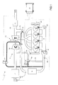
- Number 1 in Figure 1 indicates as a whole an internal combustion engine supercharged by a turbosupercharge system 2.
- Internal combustion engine 1 comprises four cylinders 3, each connected to an intake manifold 4 by at least one intake valve (not shown), and to an exhaust manifold 5 by at least one exhaust valve (not shown).
- Intake manifold 4 is supplied with fresh (i.e. outside) air by an intake pipe 6, which is fitted with an air filter 7, is regulated by a butterfly valve 8, and is fitted with an intercooler 9 for cooling the air intake.
- Exhaust manifold 5 is connected to an exhaust pipe 10, which feeds the exhaust gas produced by combustion to an exhaust system, which expels it into the atmosphere, and normally comprises at least one catalyst 11, and at least one muffler (not shown) downstream from catalyst 11.
- Turbosupercharge system 2 of internal combustion engine 1 comprises a turbosupercharger 12, in turn comprising a turbine 13 located along exhaust pipe 10 and rotated at high speed by the exhaust gas from cylinders 3; and a compressor 14 located along intake pipe 6, and connected mechanically to and rotated by turbine 13 to increase the air pressure in intake pipe 6.
- Exhaust pipe 10 is fitted with a bypass pipe 15 parallel-connected to turbine 13, with its ends connected upstream and downstream from turbine 13, and which is fitted with a wastegate valve 16 controlled by an actuator 17 to regulate exhaust gas flow along bypass pipe 15.
- Intake pipe 6 is fitted with a bypass pipe 18 parallel-connected to compressor 14, with its ends connected upstream and downstream from compressor 14, and which is fitted with a Poff valve 19 controlled by an actuator 20 to regulate (more specifically, reduce) supercharge pressure along bypass pipe 18 (or alternatively by means of an air-vent).
- Internal combustion engine 1 is controlled by an electronic central control unit 21, which controls operation of all the component parts of internal combustion engine 1, including turbosupercharge system 2, and in particular actuators 17 and 20 controlling wastegate valve 16 and Poff valve 19.
- Electronic central control unit 21 is connected to sensors 22 for measuring the temperature To and pressure P o along intake pipe 6, upstream from compressor 14; sensors 23 for measuring pressure along intake pipe 6, upstream from butterfly valve 8; sensors 24 for measuring temperature and pressure in intake manifold 4; a sensor 25 for determining the angular position (and therefore rotation speed) of the drive shaft of internal combustion engine 1; and a sensor 26 for determining the phase of the intake and/or exhaust valve. It is important to note that there are no sensors for determining the rotation speed of turbosupercharger 12.
- electronic central control unit 21 provides for keeping the operating range of turbosupercharger 12 within a useful area.
- the following is a description of the way in which electronic central control unit 21 keeps the operating range of turbosupercharger 12 within a useful area close to the saturation line.
- the characteristic curves of compressor 14 are analysed in a reduced mass flow/compression ratio graph.
- An example of the characteristic curves of a commercial compressor 14 is shown in Figure 2 .
- the characteristic curves in Figure 2 are normally at an absolute reference temperature T o-ref and absolute reference pressure P o-ref .
- T o-ref absolute reference temperature
- P o-ref absolute reference pressure
- the characteristic curves of compressor 14 are analysed to determine a rotation speed curve 27 of turbosupercharger 12; and a pump curve 28 of turbosupercharger 12.
- Two limit operation curves 29 and 30 are determined from curves 27 and 28, and used to limit the engine control pressure target downstream from compressor 14.
- Limit operation curve 29 is determined by determining a threshold S 1 establishing the distance between limit operation curve 29 and rotation speed curve 27 of turbosupercharger 12; and, similarly, limit operation curve 30 is determined by determining a threshold S 2 establishing the distance between limit operation curve 30 and pump curve 28 of turbosupercharger 12.
- Curves 27 and 28 are also used to determine two intervention curves 31 and 32 relative to wastegate valve 16 regulating bypass pipe 15 of turbine 13; and two intervention curves 33 and 34 relative to Poff valve 19 regulating bypass pipe 18 of compressor 14.
- Intervention curve 31 of wastegate valve 16 is determined by determining a threshold S 3 establishing the distance between limit operation curve 29 and intervention curve 31 of wastegate valve 16; and, similarly, intervention curve 32 of wastegate valve 16 is determined by determining a threshold S 4 establishing the distance between intervention curve 32 of wastegate valve 16 and pump curve 28 of turbosupercharger 12.
- Intervention curve 33 of Poff valve 19 is determined by determining a threshold S 5 establishing the distance between limit operation curve 29 and intervention curve 33 of Poff valve 19; and, similarly, intervention curve 34 of Poff valve 19 is determined by determining a constant or variable threshold S 6 establishing the distance between intervention curve 34 of Poff valve 19 and pump curve 28 of turbosupercharger 12.
- intervention curves 31 and 32 of wastegate valve 16 are located inwards of intervention curves 33 and 34 of Poff valve 19 (i.e. thresholds S 3 and S 4 are larger than thresholds S 5 and S 6 ). This is because, in the event curves 27 and 28 are exceeded, only wastegate valve 16 is preferably opened to limit turbosupercharger 12; and, only if opening wastegate valve 16 is insufficient, is Poff valve 19 also opened.
- electronic central control unit 21 uses limit operation curves 29 and 30 to limit the engine control pressure target downstream from compressor 14.
- the engine control implemented in electronic central control unit 21 determines, in known manner and as a function of the engine operating condition, a pressure target representing the best pressure downstream from compressor 14. If compatible with limit operation curves 29 and 30 (i.e. below the value determined as a function of limit operation curves 29 and 30), the pressure target downstream from compressor 14 is maintained. Conversely, if incompatible with limit operation curves 29 and 30 (i.e. above the value determined as a function of limit operation curves 29 and 30), the pressure target downstream from compressor 14 is limited to the maximum value compatible with limit operation curves 29 and 30.
- electronic central control unit 21 uses intervention curves 31 and 32 of wastegate valve 16 to open wastegate gate valve 16, if necessary, to maximum, regardless of the engine control target (i.e. regardless of engine control target requests).
- electronic central control unit 21 uses intervention curves 33 and 34 of Poff valve 19 to open Poff valve 19, if necessary, regardless of the engine control target (i.e. regardless of engine control target requests). More specifically, electronic central control unit 21 determines (as described) the current reduced mass flow Q AHR of compressor 14; determines the current compression ratio CR of compressor 14 (simply the ratio between the pressure measured by sensor 23 downstream from compressor 14, and the pressure measured by sensor 22 upstream from compressor 14); and opens Poff valve 19, regardless of the engine control target, if the point defined by the current reduced mass flow Q AHR and current compression ratio CR in the reduced mass flow/compression ratio graph is outside intervention curves 33 and 34 of Poff valve 19 (i.e. if current compression ratio CR is higher than the compression ratio CR in intervention curves 33 and 34 at the current reduced mass flow Q AHR .
- Electronic central control unit 21 is also designed to improve management of the turbosupercharger 12 operating range area close to pump curve 28, and, more specifically, to adjust operation of turbosupercharger 12, depending on whether the engine is accelerating (i.e. demanding more torque, power or airflow), decelerating (i.e. demanding less torque, power or airflow), or stationary.
- electronic central control unit 21 is designed to modify at least one of the characteristic operating curves of compressor 14 (i.e. pump curve 28 of compressor 14, intervention curves 32 and 34 of wastegate valve 16 and Poff valve 19, and limit operation curve 30).
- characteristic operating curves 30, 32, 34 of compressor 14 are modified with respect to pump curve 28 of compressor 14, so turbosupercharger 12 can be controlled to keep reduced mass flow Q AHR and compression ratio CR within the new limit defined by the modified characteristic operating curves 30, 32, 34.
- pump curve 28 of compressor 14 is shifted up when internal combustion engine 1 is accelerating, and down when internal combustion engine 1 is decelerating.
- characteristic operating curves 30, 32, 34 of compressor 14 may also be modified by shifting them closer to or away from pump curve 28 of compressor 14.
- Characteristic operating curves 30, 32, 34 of compressor 14 are actually modified by working on respective thresholds, S 2 , S 4 , S 6 defining the distances between pump curve 28 and limit operation curve 30, and intervention curves 32, 34 of wastegate valve 16 and Poff valve 19 respectively.
- Characteristic operating curves 30, 32, 34 of compressor 14 and pump curve 28 are modified by means of a dynamic index ⁇ dyn determined as a function of the mass flow dynamics of compressor 14, and, in a preferred and more accurate variation, as a function of the dynamics of reduced mass flow Q AHR of compressor 14.
- Dynamic index ⁇ dyn is also determined as a function of reduced mass flow Q AHR of compressor 14.
- dynamic index ⁇ dyn is determined from the real (or current) reduced mass flow Q AHR of compressor 14, and the dynamics of the target reduced mass flow Q AHR of compressor 14 (supplied by the engine control).
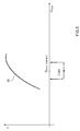
- pump curve 28 of compressor 14 is modified by shifting it up or down (i.e. with respect to the compression ratio CR axis) by an amount equal to dynamic index ⁇ dyn.
- characteristic operating curve 30, 32, 34 of compressor 14 is modified by working on respective threshold S 2 , S 4 , S 6 , and, in a first variation, is shifted up or down, with respect to the compression ratio CR axis, by an amount equal to dynamic index ⁇ dyn.
- Respective threshold S 2 , S 4 , S 6 is thus increased or reduced by an amount equal to dynamic index ⁇ dyn, which, in this case, simply represents an increase or reduction in compression ratio CR of respective threshold S 2 , S 4 , S 6 .
- Characteristic operating curves 30, 32, 34 and pump curve 28 of compressor 14 may have different dynamic indexes ⁇ dyn.
- dynamic index ⁇ dyn simply represents a reduced mass flow Q AHR which is subtracted from or added to the current reduced mass flow Q AHR _ CURRENT .
- Electronic central control unit 21 is designed to determine and correct current reduced mass flow Q AHR_CURRENT by subtracting or adding a quantity equal to dynamic index ⁇ dyn. This variation produces a rightward shift (when decelerating) or a leftward shift (when accelerating) along the reduced mass flow Q AHR axis, by an amount varying as a function of dynamic index ⁇ dyn. Electronic central control unit 21 thus implements the control strategy using the current reduced mass flow Q AHR corrected by dynamic index ⁇ dyn.
- Q AHR Q AH ⁇ T o T orif ⁇ P orif P o
- Absolute reference temperature T oref and absolute reference pressure P Oref are the conditions in which the characteristic curves of compressor 14, i.e. curves 27-34, are determined, and are design data known beforehand; the absolute temperature To and absolute pressure P o upstream from compressor 14 are measured by sensors 22; and the mass flow Q AH of compressor 14 may either be measured by a flow sensor or calculated in known manner by electronic central control unit 21.
- the absolute temperature To upstream from compressor 14 (i.e. substantially ambient temperature) need not necessarily be measured; in which case, reduced mass flow Q AHR may be 'partly' normalized on the basis of the ratio between pressures P o and P Oref , without taking into account the ratio between temperatures To and T Oref .
- the step of modifying characteristic operating curves 30, 32, 34 of compressor 14 using dynamic index ⁇ dyn comprises only modifying intervention curve 34 of Poff valve 19, i.e. correcting respective threshold S 6 .
- intervention curve 34 of Poff valve 19 is modified as a function of dynamic index ⁇ dyn; and respective thresholds S 4 and S 2 of intervention curve 32 of wastegate valve 16 and limit operation curve 30 remain unchanged with respect to pump curve 28.
- the control method also provides for determining a hysteresis operator HYS WG for intervention curve 32 of wastegate valve 16; and a hysteresis operator HYS Poff for intervention curve 34 of Poff valve 19.
- At least one of hysteresis operators HYS WG , HYS Poff , in particular hysteresis operator HYS WG relative to opening wastegate valve 16, is fixed.
- Hysteresis operator HYS Poff varies as a function of reduced mass flow Q AHR of compressor 14, the dynamics of reduced mass flow Q AHR of compressor 14 (i.e. dynamic index ⁇ dyn, which in turn is a function of reduced mass flow Q AHR and the dynamics of reduced mass flow Q AHR ) , and atmospheric pressure P atm .
- the dynamics of reduced mass flow Q AHR are represented by the rate of change of the target reduced mass flow Q AHR of compressor 14.
- Electronic central control unit 21 is designed to determine the target reduced mass flow Q AHR supplied by the engine control, and to filter it using a first-order, preferably low-pass, filter.
- the correction dynamic index ⁇ dyn is thus calculated as the difference between the target reduced mass flow Q AHR supplied by the engine control, and the filtered target reduced mass flow Q AHR also supplied by the engine control.
- the dynamics of reduced mass flow Q AHR are determined as a function of the dynamics of butterfly valve 8 regulating fresh air along intake pipe 6 to intake manifold 4, or the dynamics of other airflow-regulating actuators (e.g. valve timing and lift).
- a simplified (i.e. less accurate) embodiment may employ current mass flow Q AH (not reduced) or the target mass flow Q AHR (reduced or not) .
- electronic central control unit 21 is designed to open Poff valve 19 (regardless of the engine control target) when the point defined by current reduced mass flow Q AHR and current compression ratio CR on the reduced mass flow/compression ratio graph lies outside intervention curve 34 of Poff valve 19; and, similarly, to close Poff valve 19 (regardless of the engine control target) as soon as the point defined by current reduced mass flow Q AHR and current compression ratio CR on the reduced mass flow/compression ratio graph returns within the limit area defined by a Poff valve 19 closure curve 35 (determined as a function of hysteresis operator HYS Poff ).
- closure of Poff valve 19 may be delayed.
- a limit time interval ⁇ t, and a tolerance value TV which varies as a function of reduced mass flow Q AHR , are determined at a preliminary setup stage.
- electronic central control unit 21 is designed not to delay closure of Poff valve 19 for longer than the limit time interval ⁇ t, i.e. closes Poff valve 19 after a time lapse equal to limit time interval ⁇ t.
- Poff valve 19 is opened early in at least one of the following conditions : - ⁇ target_fil - ⁇ target > S ⁇ 1 where ⁇ target_fil is the filtered target closure angle of butterfly valve 8; ⁇ target is the target closure angle of butterfly valve 8; and S1 is a threshold value determined at a preliminary setup stage; - Pt - P ⁇ t target > S ⁇ 2 where Pt is the supercharge pressure of turbosupercharger 12; Pt target is the target supercharge pressure of turbosupercharger 12; and S2 is a threshold value determined at a preliminary setup stage; - Q AHR > S ⁇ 3 where Q AHR is reduced mass flow; and S3 is a threshold value determined at a preliminary setup stage.
- electronic central control unit 21 is designed to prolong opening of Poff valve 19 by a predetermined time interval ⁇ t 2 , e.g. by means of a timer, which is started the instant the above conditions no longer apply (i.e. the instant which should correspond to closure of Poff valve 19).
- Poff valve 19 is kept open as long as the difference between supercharge pressure Pt and target supercharge pressure Pt target of turbosupercharger 12 is less than or equal to a threshold value S4 determined at a preliminary setup stage.
- control method described has numerous advantages, by being cheap and easy to implement, not requiring particularly high computing power of electronic central control unit 21, and not requiring any additional component parts (in particular, sensors or actuators) over and above those already provided on modern internal combustion engines.
- the control method described provides for enhancing both acceleration and deceleration performance of turbosupercharger 12 in the portion of the useful operating range close to pump curve 28, and so preventing failure or malfunctioning, by taking into account the dynamics (i.e. rate of change) of reduced mass flow Q AHR of compressor 14, as opposed to simply reduced mass flow Q AHR .
Landscapes
- Engineering & Computer Science (AREA)
- Chemical & Material Sciences (AREA)
- Combustion & Propulsion (AREA)
- Mechanical Engineering (AREA)
- General Engineering & Computer Science (AREA)
- Supercharger (AREA)
- Testing Of Engines (AREA)
- Control Of Turbines (AREA)
Abstract
Description
- The present invention relates to a turbosupercharged internal combustion engine control method.
- As is known, some internal combustion engines are equipped with a turbosupercharge system for increasing engine power using the heat content of the exhaust gas to compress the air intake of the engine and so increase volumetric efficiency.
- A turbosupercharge system comprises a turbosupercharger with a turbine fitted along the exhaust pipe and rotated at high speed by the exhaust gas from the engine, and a compressor rotated by the turbine and located along the air intake pipe to compress the air intake of the engine.
- In a turbosupercharge system, the operating range of the turbosupercharger must be kept within a useful area, depending on the engine operating condition, for both functional reasons (i.e. to avoid irregular or, at any rate, low-efficiency operation) and structural reasons (i.e. to avoid damaging the turbosupercharger).
- More specifically, the useful operating range area is bounded, on the left of a reduced mass flow/compression ratio graph, by a pump line, and on the right by a so-called 'saturation line'. The pump line thus defines a first 'off-limit' area, and is defined by the points in which the internal aerodynamic balance of the compressor is disrupted, with periodic, loud, violent flow rejection, and possibly destructive effects on the blades. The so-called 'saturation line' defines a second 'off-limit' area, corresponds to sonic conditions (and hence flow cutoff) at the turbine inlet, and defines the maximum flow the compressor can supply under given intake environment conditions.
- Patent Application
EP1741895A1 describes a method of controlling an internal combustion engine supercharged by a turbosupercharger comprising a compressor; a turbine for rotating the compressor using the exhaust gas from the engine; and a wastegate valve for regulating exhaust gas flow to the turbine, to control rotation of the turbine according to a target supercharge pressure from the compressor. The control method comprises the steps of measuring the air intake pressure of the compressor; determining mass flow of the compressor; calculating - by means of a compressor operation map, and as a function of the predetermined limit rotation speed, the air pressure measurement, and mass flow - a limit supercharge pressure correlated to the air pressure obtainable from the compressor when the turbine rotates at a speed substantially equal to the predetermined limit speed; determining whether a target supercharge pressure satisfies a given relationship with the calculated limit supercharge pressure; and activating the wastegate valve, if the relationship is satisfied, to control turbine rotation speed as a function of the limit supercharge pressure, and so rotate the turbosupercharger at substantially the predetermined limit speed. - Patent Application
EP2014894A1 describes a turbosupercharged internal combustion engine control method, which comprises establishing, in a reduced mass flow/compression ratio graph, at least one limit operation curve; at least one intervention curve relative to a wastegate valve regulating a turbine bypass pipe; and at least one intervention curve relative to a Poff valve regulating a compressor bypass pipe. The control method described uses the limit operation curve to limit the engine control pressure target downstream from the compressor; opens the wastegate valve when the wastegate valve intervention curve is exceeded; and opens the Poff valve when the Poff valve intervention curve is exceeded. - The
EP2014894A1 control method keeps the turbosupercharger within the useful area, regardless of the operating condition of the internal combustion engine, to prevent failure or damage, but fails to enhance performance of the turbosupercharger. - Patent Application
EP1323912A1 describes a turbosupercharged internal combustion engine control method, which determines a parameter depending on mass flow of the compressor, and by which to control the turbosupercharger to protect the compressor and keep the actual pressure within the specified compressor operating range. - That is, the
EP1323912A1 control method determines a parameter depending on the mass flow of the compressor, and by which to control the turbosupercharger to protect the compressor, keep the actual pressure within the safe operating range of the compressor, and so prevent failure or damage, but also fails to enhance performance of the turbosupercharger. - It is an object of the present invention to provide a turbosupercharged internal combustion engine control method that is cheap and easy to implement, and which in particular provides for enhancing performance of the turbosupercharger in a portion of the useful turbosupercharger operating area close to the pump line.
- According to the present invention, there is provided a turbosupercharged internal combustion engine control method as claimed in the accompanying Claims.
- A non-limiting embodiment of the present invention will be described by way of example with reference to the accompanying drawings, in which :
-
Figure 1 shows a schematic of a turbosupercharged internal combustion engine comprising an electronic central control unit implementing a control method in accordance with the present invention; -
Figure 2 shows a reduced mass flow/compression ratio graph illustrating the characteristic curves of a compressor of theFigure 1 turbosupercharger; -
Figures 3 to 6 show reduced mass flow/compression ratio graphs illustrating limit operation curves and intervention curves employed in the control method implemented in theFigure 1 electronic central control unit. -
Number 1 inFigure 1 indicates as a whole an internal combustion engine supercharged by aturbosupercharge system 2. -
Internal combustion engine 1 comprises fourcylinders 3, each connected to anintake manifold 4 by at least one intake valve (not shown), and to anexhaust manifold 5 by at least one exhaust valve (not shown).Intake manifold 4 is supplied with fresh (i.e. outside) air by anintake pipe 6, which is fitted with anair filter 7, is regulated by abutterfly valve 8, and is fitted with anintercooler 9 for cooling the air intake.Exhaust manifold 5 is connected to anexhaust pipe 10, which feeds the exhaust gas produced by combustion to an exhaust system, which expels it into the atmosphere, and normally comprises at least onecatalyst 11, and at least one muffler (not shown) downstream fromcatalyst 11. -
Turbosupercharge system 2 ofinternal combustion engine 1 comprises aturbosupercharger 12, in turn comprising aturbine 13 located alongexhaust pipe 10 and rotated at high speed by the exhaust gas fromcylinders 3; and acompressor 14 located alongintake pipe 6, and connected mechanically to and rotated byturbine 13 to increase the air pressure inintake pipe 6. -
Exhaust pipe 10 is fitted with abypass pipe 15 parallel-connected toturbine 13, with its ends connected upstream and downstream fromturbine 13, and which is fitted with awastegate valve 16 controlled by anactuator 17 to regulate exhaust gas flow alongbypass pipe 15. Intakepipe 6 is fitted with abypass pipe 18 parallel-connected tocompressor 14, with its ends connected upstream and downstream fromcompressor 14, and which is fitted with aPoff valve 19 controlled by anactuator 20 to regulate (more specifically, reduce) supercharge pressure along bypass pipe 18 (or alternatively by means of an air-vent). -
Internal combustion engine 1 is controlled by an electroniccentral control unit 21, which controls operation of all the component parts ofinternal combustion engine 1, includingturbosupercharge system 2, and inparticular actuators wastegate valve 16 andPoff valve 19. Electroniccentral control unit 21 is connected tosensors 22 for measuring the temperature To and pressure Po alongintake pipe 6, upstream fromcompressor 14;sensors 23 for measuring pressure alongintake pipe 6, upstream frombutterfly valve 8;sensors 24 for measuring temperature and pressure inintake manifold 4; asensor 25 for determining the angular position (and therefore rotation speed) of the drive shaft ofinternal combustion engine 1; and asensor 26 for determining the phase of the intake and/or exhaust valve. It is important to note that there are no sensors for determining the rotation speed ofturbosupercharger 12. - Among other things, electronic
central control unit 21 provides for keeping the operating range ofturbosupercharger 12 within a useful area. The following is a description of the way in which electroniccentral control unit 21 keeps the operating range ofturbosupercharger 12 within a useful area close to the saturation line. - When designing and tuning
internal combustion engine 1, the characteristic curves of compressor 14 (provided by the maker of turbosupercharger 12) are analysed in a reduced mass flow/compression ratio graph. An example of the characteristic curves of acommercial compressor 14 is shown inFigure 2 . - The characteristic curves in
Figure 2 are normally at an absolute reference temperature To-ref and absolute reference pressure Po-ref.On the left of the reduced mass flow/compression ratio graph is a first 'off-limit' area bounded by the pump line, which is defined by the points in which the internal aerodynamic balance ofcompressor 14 is disrupted, with periodic, loud, violent flow rejection at the inlet, and possibly destructive effects on the blades. - On the right of the reduced mass flow/compression ratio graph is a second 'off-limit' area bounded by the so-called 'saturation line', which corresponds to sonic conditions (and hence flow cutoff) at the inlet of
turbine 13, and defines themaximum flow compressor 14 can supply under given intake environment conditions. - As shown in
Figure 3 , the characteristic curves ofcompressor 14 are analysed to determine arotation speed curve 27 ofturbosupercharger 12; and apump curve 28 ofturbosupercharger 12. Twolimit operation curves curves compressor 14.Limit operation curve 29 is determined by determining a threshold S1 establishing the distance betweenlimit operation curve 29 androtation speed curve 27 ofturbosupercharger 12; and, similarly,limit operation curve 30 is determined by determining a threshold S2 establishing the distance betweenlimit operation curve 30 andpump curve 28 ofturbosupercharger 12. -
Curves intervention curves wastegate valve 16 regulatingbypass pipe 15 ofturbine 13; and twointervention curves Poff valve 19 regulatingbypass pipe 18 ofcompressor 14.Intervention curve 31 ofwastegate valve 16 is determined by determining a threshold S3 establishing the distance betweenlimit operation curve 29 andintervention curve 31 ofwastegate valve 16; and, similarly,intervention curve 32 ofwastegate valve 16 is determined by determining a threshold S4 establishing the distance betweenintervention curve 32 ofwastegate valve 16 andpump curve 28 ofturbosupercharger 12.Intervention curve 33 ofPoff valve 19 is determined by determining a threshold S5 establishing the distance betweenlimit operation curve 29 andintervention curve 33 ofPoff valve 19; and, similarly,intervention curve 34 ofPoff valve 19 is determined by determining a constant or variable threshold S6 establishing the distance betweenintervention curve 34 ofPoff valve 19 andpump curve 28 ofturbosupercharger 12. - It is important to note how
intervention curves wastegate valve 16 are located inwards ofintervention curves event curves wastegate valve 16 is preferably opened to limitturbosupercharger 12; and, only if openingwastegate valve 16 is insufficient, isPoff valve 19 also opened. - When
internal combustion engine 1 is running, electroniccentral control unit 21 useslimit operation curves compressor 14. In other words, the engine control implemented in electroniccentral control unit 21 determines, in known manner and as a function of the engine operating condition, a pressure target representing the best pressure downstream fromcompressor 14. If compatible withlimit operation curves 29 and 30 (i.e. below the value determined as a function oflimit operation curves 29 and 30), the pressure target downstream fromcompressor 14 is maintained. Conversely, if incompatible withlimit operation curves 29 and 30 (i.e. above the value determined as a function oflimit operation curves 29 and 30), the pressure target downstream fromcompressor 14 is limited to the maximum value compatible withlimit operation curves - When
internal combustion engine 1 is running, electroniccentral control unit 21 usesintervention curves wastegate valve 16 to openwastegate gate valve 16, if necessary, to maximum, regardless of the engine control target (i.e. regardless of engine control target requests). - Similarly, when
internal combustion engine 1 is running, electroniccentral control unit 21 usesintervention curves Poff valve 19 to openPoff valve 19, if necessary, regardless of the engine control target (i.e. regardless of engine control target requests). More specifically, electroniccentral control unit 21 determines (as described) the current reduced mass flow QAHR ofcompressor 14; determines the current compression ratio CR of compressor 14 (simply the ratio between the pressure measured bysensor 23 downstream fromcompressor 14, and the pressure measured bysensor 22 upstream from compressor 14); and opensPoff valve 19, regardless of the engine control target, if the point defined by the current reduced mass flow QAHR and current compression ratio CR in the reduced mass flow/compression ratio graph isoutside intervention curves intervention curves - Electronic
central control unit 21 is also designed to improve management of theturbosupercharger 12 operating range area close topump curve 28, and, more specifically, to adjust operation ofturbosupercharger 12, depending on whether the engine is accelerating (i.e. demanding more torque, power or airflow), decelerating (i.e. demanding less torque, power or airflow), or stationary. - When
internal combustion engine 1 is running, electroniccentral control unit 21 is designed to modify at least one of the characteristic operating curves of compressor 14 (i.e. pump curve 28 ofcompressor 14,intervention curves wastegate valve 16 andPoff valve 19, and limit operation curve 30). - More specifically,
characteristic operating curves compressor 14 are modified with respect topump curve 28 ofcompressor 14, soturbosupercharger 12 can be controlled to keep reduced mass flow QAHR and compression ratio CR within the new limit defined by the modifiedcharacteristic operating curves - The best modification has been found to be achieved by shifting
pump curve 28 ofcompressor 14 up or down on the reduced mass flow/compression ratio graph (i.e. with respect to the compression ratio CR axis). More specifically,pump curve 28 is shifted up wheninternal combustion engine 1 is accelerating, and down wheninternal combustion engine 1 is decelerating. - In a preferred variation,
characteristic operating curves compressor 14 may also be modified by shifting them closer to or away frompump curve 28 ofcompressor 14. -
Characteristic operating curves compressor 14 are actually modified by working on respective thresholds, S2, S4, S6 defining the distances betweenpump curve 28 andlimit operation curve 30, andintervention curves wastegate valve 16 andPoff valve 19 respectively. -
Characteristic operating curves compressor 14 andpump curve 28 are modified by means of a dynamic index Δdyn determined as a function of the mass flow dynamics ofcompressor 14, and, in a preferred and more accurate variation, as a function of the dynamics of reduced mass flow QAHR ofcompressor 14. - Dynamic index Δdyn is also determined as a function of reduced mass flow QAHR of
compressor 14. - It is important to note that, in a preferred variation, dynamic index Δdyn is determined from the real (or current) reduced mass flow QAHR of
compressor 14, and the dynamics of the target reduced mass flow QAHR of compressor 14 (supplied by the engine control). - Using dynamic index Δdyn,
pump curve 28 ofcompressor 14 is modified by shifting it up or down (i.e. with respect to the compression ratio CR axis) by an amount equal to dynamic index Δdyn. - Using dynamic index Δdyn,
characteristic operating curve compressor 14 is modified by working on respective threshold S2, S4, S6, and, in a first variation, is shifted up or down, with respect to the compression ratio CR axis, by an amount equal to dynamic index Δdyn. Respective threshold S2, S4, S6 is thus increased or reduced by an amount equal to dynamic index Δdyn, which, in this case, simply represents an increase or reduction in compression ratio CR of respective threshold S2, S4, S6. - Characteristic operating curves 30, 32, 34 and
pump curve 28 ofcompressor 14 may have different dynamic indexes Δdyn. - In another variation shown in
Figure 5 , dynamic index Δdyn simply represents a reduced mass flow QAHR which is subtracted from or added to the current reduced mass flow QAHR_CURRENT. - Electronic
central control unit 21 is designed to determine and correct current reduced mass flow QAHR_CURRENT by subtracting or adding a quantity equal to dynamic index Δdyn. This variation produces a rightward shift (when decelerating) or a leftward shift (when accelerating) along the reduced mass flow QAHR axis, by an amount varying as a function of dynamic index Δdyn. Electroniccentral control unit 21 thus implements the control strategy using the current reduced mass flow QAHR corrected by dynamic index Δdyn. - This embodiment has been found to give exactly equivalent results to those of the
Figure 4 embodiment. - The current reduced mass flow QAHR of
compressor 14 is determined using the equation :
- QAH
- mass flow of
compressor 14 - QAHR
- reduced mass flow of
compressor 14 - To
- absolute temperature upstream from
compressor 14 - Po
- absolute pressure upstream from
compressor 14 - T0ref
- absolute reference temperature
- POref
- absolute reference pressure
- Absolute reference temperature Toref and absolute reference pressure POref are the conditions in which the characteristic curves of
compressor 14, i.e. curves 27-34, are determined, and are design data known beforehand; the absolute temperature To and absolute pressure Po upstream fromcompressor 14 are measured bysensors 22; and the mass flow QAH ofcompressor 14 may either be measured by a flow sensor or calculated in known manner by electroniccentral control unit 21. - In a different embodiment not shown, the absolute temperature To upstream from compressor 14 (i.e. substantially ambient temperature) need not necessarily be measured; in which case, reduced mass flow QAHR may be 'partly' normalized on the basis of the ratio between pressures Po and POref, without taking into account the ratio between temperatures To and TOref.
- In a first variation, the step of modifying characteristic operating curves 30, 32, 34 of
compressor 14 using dynamic index Δdyn comprises only modifyingintervention curve 34 ofPoff valve 19, i.e. correcting respective threshold S6. In other words,intervention curve 34 ofPoff valve 19 is modified as a function of dynamic index Δdyn; and respective thresholds S4 and S2 ofintervention curve 32 ofwastegate valve 16 andlimit operation curve 30 remain unchanged with respect to pumpcurve 28. - The control method also provides for determining a hysteresis operator HYSWG for
intervention curve 32 ofwastegate valve 16; and a hysteresis operator HYSPoff forintervention curve 34 ofPoff valve 19. - In a preferred variation, at least one of hysteresis operators HYSWG, HYSPoff, in particular hysteresis operator HYSWG relative to opening
wastegate valve 16, is fixed. - Hysteresis operator HYSPoff, on the other hand, varies as a function of reduced mass flow QAHR of
compressor 14, the dynamics of reduced mass flow QAHR of compressor 14 (i.e. dynamic index Δdyn, which in turn is a function of reduced mass flow QAHR and the dynamics of reduced mass flow QAHR) , and atmospheric pressure Patm. - In a preferred variation, the dynamics of reduced mass flow QAHR are represented by the rate of change of the target reduced mass flow QAHR of
compressor 14. - Electronic
central control unit 21 is designed to determine the target reduced mass flow QAHR supplied by the engine control, and to filter it using a first-order, preferably low-pass, filter. - The correction dynamic index Δdyn is thus calculated as the difference between the target reduced mass flow QAHR supplied by the engine control, and the filtered target reduced mass flow QAHR also supplied by the engine control.
- In another variation, the dynamics of reduced mass flow QAHR are determined as a function of the dynamics of
butterfly valve 8 regulating fresh air alongintake pipe 6 tointake manifold 4, or the dynamics of other airflow-regulating actuators (e.g. valve timing and lift). - Instead of current reduced mass flow QAHR, a simplified (i.e. less accurate) embodiment may employ current mass flow QAH (not reduced) or the target mass flow QAHR (reduced or not) .
- As shown in
Figure 6 , electroniccentral control unit 21 is designed to open Poff valve 19 (regardless of the engine control target) when the point defined by current reduced mass flow QAHR and current compression ratio CR on the reduced mass flow/compression ratio graph lies outsideintervention curve 34 ofPoff valve 19; and, similarly, to close Poff valve 19 (regardless of the engine control target) as soon as the point defined by current reduced mass flow QAHR and current compression ratio CR on the reduced mass flow/compression ratio graph returns within the limit area defined by aPoff valve 19 closure curve 35 (determined as a function of hysteresis operator HYSPoff). - In another variation, closure of
Poff valve 19 may be delayed. In which case, a limit time interval Δt, and a tolerance value TV, which varies as a function of reduced mass flow QAHR, are determined at a preliminary setup stage. - As soon as the point defined by current reduced mass flow QAHR and current compression ratio CR on the reduced mass flow/compression ratio graph returns within the limit area defined by
Poff valve 19closure curve 35, a timer is started, and closure ofPoff valve 19 is delayed, i.e.Poff valve 19 is kept open, as long as the difference between the target pressure value, supplied by the engine control, and the current pressure value does not exceed, i.e. is below, tolerance value TV. - In a preferred variation, electronic
central control unit 21 is designed not to delay closure ofPoff valve 19 for longer than the limit time interval Δt, i.e. closesPoff valve 19 after a time lapse equal to limit time interval Δt. - The control method described so far may be enhanced by an algorithm for opening Poff valve 19 (in particular, early) as a function of the closure dynamics of
butterfly valve 8regulating intake pipe 6 of superchargedinternal combustion engine 1. More specifically,Poff valve 19 is opened early in at least one of the following conditions :
where αtarget_fil is the filtered target closure angle ofbutterfly valve 8; αtarget is the target closure angle ofbutterfly valve 8; and S1 is a threshold value determined at a preliminary setup stage;
where Pt is the supercharge pressure ofturbosupercharger 12; Pttarget is the target supercharge pressure ofturbosupercharger 12; and S2 is a threshold value determined at a preliminary setup stage;
where QAHR is reduced mass flow; and S3 is a threshold value determined at a preliminary setup stage. - In a preferred variation, electronic
central control unit 21 is designed to prolong opening ofPoff valve 19 by a predetermined time interval Δt2, e.g. by means of a timer, which is started the instant the above conditions no longer apply (i.e. the instant which should correspond to closure of Poff valve 19). - In another variation,
Poff valve 19 is kept open as long as the difference between supercharge pressure Pt and target supercharge pressure Pttarget ofturbosupercharger 12 is less than or equal to a threshold value S4 determined at a preliminary setup stage. - The control method described has numerous advantages, by being cheap and easy to implement, not requiring particularly high computing power of electronic
central control unit 21, and not requiring any additional component parts (in particular, sensors or actuators) over and above those already provided on modern internal combustion engines. - The control method described provides for enhancing both acceleration and deceleration performance of
turbosupercharger 12 in the portion of the useful operating range close to pumpcurve 28, and so preventing failure or malfunctioning, by taking into account the dynamics (i.e. rate of change) of reduced mass flow QAHR ofcompressor 14, as opposed to simply reduced mass flow QAHR.
Claims (27)
- A method of controlling an internal combustion engine (1) supercharged by a turbosupercharger (12) comprising a turbine (13) and a compressor (14); the control method comprising the steps of :determining, in a reduced mass flow/compression ratio graph, at least one limit operation curve (28, 30, 32, 34) of the compressor (14) representing a limit of the operating range of the compressor (14); andcontrolling the turbosupercharger (12) to keep the actual reduced mass flow (QAHR) and actual compression ratio (CR) of the compressor (14) within the limit defined by the limit operation curve (28, 30, 32, 34) of the compressor (14);the control method being characterized by comprising the further steps of :determining an index (Δdyn) varying as a function of the dynamics of the reduced mass flow (QAHR) of the compressor (14); andmodifying the limit operation curve (28, 30, 32, 34) of the compressor (14) as a function of the index (Δdyn).
- A control method as claimed in Claim 1, wherein the index (Δdyn) varies as a function of the reduced mass flow (QAHR) of the compressor (14) .
- A control method as claimed in Claim 2, wherein the dynamics of the reduced mass flow (QAHR) of the compressor (14) are the dynamics of the target reduced mass flow (QAHR) of the compressor (14) supplied by the engine control; and the reduced mass flow (QAHR) of the compressor (14) is the real reduced mass flow (QAHR) of the compressor (14).
- A control method as claimed in one of the foregoing Claims, wherein a first limit operation curve (28, 30, 32, 34) of the compressor (14) is shifted, in the reduced mass flow/compression ratio graph, by an amount which is a function of the index (Δdyn).
- A control method as claimed in Claim 4, wherein the first limit operation curve (28) of the compressor (14) is a pump curve (28) of the compressor (14), which defines the points beyond which the internal aerodynamic balance of the compressor (14) is disrupted; and the first limit operation curve (28) of the compressor (14) is shifted up, in the reduced mass flow/compression ratio graph, when the internal combustion engine (1) accelerates, and down when the internal combustion engine (1) decelerates.
- A control method as claimed in Claim 4 or 5, wherein the absolute value of the index (Δdyn) is subtracted from a current reduced mass flow (QAHR_CURRENT) of the compressor (14) when the internal combustion engine (1) decelerates, so as to shift the first limit operation curve (28) of the compressor (14) rightwards in the reduced mass flow/compression ratio graph; and the absolute value of the index (Δdyn) is added to the current reduced mass flow (QAHR_CURRENT) of the compressor (14) when the internal combustion engine (1) accelerates, so as to shift the first limit operation curve (28) of the compressor (14) leftwards in the reduced mass flow/compression ratio graph.
- A control method as claimed in one of Claims 4 to 6, and comprising the further step of determining a second limit operation curve (30, 32, 34) of the compressor (14) as a function of the first limit operation curve (28) of the compressor (14).
- A control method as claimed in Claim 7, and comprising the further step of determining the second limit operation curve (30, 32, 34) of the compressor (14) by applying a safety threshold (S2, S4, S6) to the first limit operation curve (28) of the compressor (14).
- A control method as claimed in Claim 8, and comprising the further step of modifying the second limit operation curve (30, 32, 34) of the compressor (14) as a function of the index (Δdyn), by modifying the safety threshold (S2, S4, S6) as a function of the index (Δdyn).
- A control method as claimed in Claim 9, wherein the index (Δdyn) is added to or subtracted from the safety threshold (S2, S4, S6) .
- A control method as claimed in Claim 8, wherein the safety threshold (S2, S4, S6) varies as a function of the reduced mass flow (QAHR) of the compressor (14).
- A control method as claimed in one of Claims 1 to 11, and comprising the further step of using a hysteresis operator (HYSWG, HYSPoff) for a limit operation curve (32, 34) of the compressor (14).
- A control method as claimed in Claim 12, wherein the hysteresis operator (HYSPoff) varies as a function of the reduced mass flow (QAHR) of the compressor (14) and/or atmospheric pressure (Patm) and/or the dynamics of the reduced mass flow (QAHR) of the compressor (14).
- A control method as claimed in Claim 12 or 13, wherein the hysteresis operator (HYSPoff) varies as a function of the index (Δdyn).
- A control method as claimed in one of Claims 1 to 14, wherein the dynamics of the reduced mass flow (QAHR) of the compressor (14) are defined by the rate of change of the reduced mass flow (QAHR) of the compressor (14).
- A control method as claimed in Claim 15, and comprising the further steps of :determining a target reduced mass flow (QAHR) supplied by the engine control;filtering the target reduced mass flow (QAHR) with a low-pass filter; andcalculating the rate of change of the reduced mass flow (QAHR) of the compressor (14) as the difference between the target reduced mass flow (QAHR) and the filtered target reduced mass flow (QAHR) .
- A control method as claimed in one of Claims 1 to 14, wherein the dynamics of the reduced mass flow (QAHR) of the compressor (14) are determined as a function of the dynamics of a butterfly valve (8) regulating an intake pipe (6) of the supercharged internal combustion engine (1).
- A control method as claimed in one of Claims 1 to 17, and comprising the further steps of :using a first limit operation curve (30) of the compressor (14) to saturate a target supercharge pressure;using a second limit operation curve (32) of the compressor (14) to control a wastegate valve (16), in such a manner as to open the wastegate valve (16) when the second limit operation curve (32) of the compressor (14) is exceeded; andusing a third limit operation curve (34) of the compressor (14) to control a Poff valve (19), in such a manner as to open the Poff valve (19) when the third limit operation curve (34) of the compressor (14) is exceeded.
- A control method as claimed in Claim 18, and comprising the further steps of :determining a limit time interval (Δt) at a preliminary setup stage; anddelaying closure of the Poff valve (19) by a time interval at most equal to the limit time interval (Δt).
- A control method as claimed in Claim 18 or 19, and comprising the further steps of :determining a tolerance value (TV) at a preliminary setup stage;calculating the difference between the current supercharge pressure of the turbosupercharger (12) and the target supercharge pressure of the turbosupercharger (12); andclosing the Poff valve (19) when the difference between the current supercharge pressure of the turbosupercharger (12) and the target supercharge pressure of the turbosupercharger (12) is less than or equal to the tolerance value (TV).
- A control method as claimed in Claim 20, wherein the tolerance value (TV) is determined as a function of the reduced mass flow (QAHR) of the compressor (14).
- A control method as claimed in one of Claims 1 to 21, wherein the supercharged internal combustion engine (1) comprises a Poff valve (19), and a butterfly valve (8) for regulating an intake pipe (6); the control method comprising the step of opening the Poff valve (19) as a function of the closure dynamics of the butterfly valve (8).
- A control method as claimed in Claim 22, and comprising the further step of determining a first safety value (S1) at a preliminary setup stage; and wherein the Poff valve (19) is opened when the difference between the filtered target closure angle of the butterfly valve (8) and the target closure angle of the butterfly valve (8) exceeds the first safety value (S1) .
- A control method as claimed in Claim 22 or 23, and comprising the further step of determining a second safety value (S2) at a preliminary setup stage; and wherein the Poff valve (19) is opened when the difference between the supercharge pressure (Pt) of the turbosupercharger (12) and the target supercharge pressure (Pttarget) of the turbosupercharger (12) exceeds the second safety value (S2).
- A control method as claimed in one of Claims 22 to 24, and comprising the further step of determining a third safety value (S3) at a preliminary setup stage; and wherein the Poff valve (19) is opened when the reduced mass flow (QAHR) of the compressor (14) exceeds the third safety value (S3).
- A control method as claimed in one of Claims 23 to 25, and comprising the further steps of :determining a limit time interval (Δt2) at a preliminary setup stage; anddelaying closure of the Poff valve (19) by a time interval at most equal to the limit time interval (Δt2).
- A control method as claimed in one of Claims 23 to 26, and comprising the further steps of :determining a fourth safety value (S4) at a preliminary setup stage;calculating the difference between the supercharge pressure (Pt) of the turbosupercharger (12) and the target supercharge pressure (Pttarget) of the turbosupercharger (12); andclosing the Poff valve (19) when the difference between the supercharge pressure (Pt) of the turbosupercharger (12) and the target supercharge pressure (Pttarget) of the turbosupercharger (12) is less than or equal to the fourth safety value (S4).
Applications Claiming Priority (1)
| Application Number | Priority Date | Filing Date | Title |
|---|---|---|---|
| ITBO2010A000604A IT1403512B1 (en) | 2010-10-11 | 2010-10-11 | METHOD OF CHECKING THE SPEED OF AN INTERNAL COMBUSTION MOTOR SUPPLIED BY A TURBOCHARGER. |
Publications (2)
| Publication Number | Publication Date |
|---|---|
| EP2439391A1 true EP2439391A1 (en) | 2012-04-11 |
| EP2439391B1 EP2439391B1 (en) | 2016-12-07 |
Family
ID=43737819
Family Applications (1)
| Application Number | Title | Priority Date | Filing Date |
|---|---|---|---|
| EP11184229.0A Active EP2439391B1 (en) | 2010-10-11 | 2011-10-06 | Turbosupercharged internal combustion engine control method |
Country Status (3)
| Country | Link |
|---|---|
| US (1) | US9008945B2 (en) |
| EP (1) | EP2439391B1 (en) |
| IT (1) | IT1403512B1 (en) |
Families Citing this family (4)
| Publication number | Priority date | Publication date | Assignee | Title |
|---|---|---|---|---|
| ITBO20120324A1 (en) * | 2012-06-12 | 2013-12-13 | Magneti Marelli Spa | METHOD OF CONTROL OF AN INTERNAL COMBUSTION ENGINE |
| AT513137B1 (en) * | 2012-09-13 | 2014-02-15 | Avl List Gmbh | Method for monitoring at least one exhaust gas turbocharger |
| US9920698B2 (en) * | 2014-04-15 | 2018-03-20 | GM Global Technology Operations LLC | Recirculation valve control systems and methods |
| CN106939826A (en) * | 2017-04-12 | 2017-07-11 | 潍柴西港新能源动力有限公司 | Natural gas engine antisurge control system and method |
Citations (4)
| Publication number | Priority date | Publication date | Assignee | Title |
|---|---|---|---|---|
| EP1323912A1 (en) | 2001-12-21 | 2003-07-02 | Delphi Technologies, Inc. | Method for controlling the boost pressure of a turbocharged internal combustion engine |
| DE10317959A1 (en) * | 2003-04-17 | 2004-11-25 | Schatz Thermo Engineering | Method of operating an internal combustion engine fitted with exhaust-gas turbocharger, especially for motor vehicles, with turbocharger kept on a high rotational speed when in partial load operation |
| EP1741895A1 (en) | 2005-07-05 | 2007-01-10 | Magneti Marelli Powertrain S.p.A. | A method and device for controlling the speed of rotation of a turbosupercharger in an internal-combustion engine |
| EP2014894A1 (en) | 2007-07-09 | 2009-01-14 | Magneti Marelli Powertrain S.p.A. | A control method for a turbocharger supercharged internal combustion engine |
Family Cites Families (6)
| Publication number | Priority date | Publication date | Assignee | Title |
|---|---|---|---|---|
| JPH09177555A (en) * | 1995-12-27 | 1997-07-08 | Toyota Motor Corp | Supercharging pressure control device for supercharger |
| US6279551B1 (en) * | 1999-04-05 | 2001-08-28 | Nissan Motor Co., Ltd. | Apparatus for controlling internal combustion engine with supercharging device |
| US7802427B2 (en) * | 2006-05-19 | 2010-09-28 | Caterpillar Inc | System and method for monitoring boost leak |
| US7650218B2 (en) * | 2007-09-20 | 2010-01-19 | Cummins Ip, Inc | Apparatus, system, and method for preventing turbocharger overspeed in a combustion engine |
| IT1401827B1 (en) * | 2010-09-27 | 2013-08-28 | Magneti Marelli Spa | METHOD OF CHECKING THE SPEED OF AN INTERNAL COMBUSTION MOTOR OVER-POWERED BY A TURBOCHARGER |
| IT1401826B1 (en) * | 2010-09-27 | 2013-08-28 | Magneti Marelli Spa | METHOD OF CHECKING THE SPEED OF AN INTERNAL COMBUSTION MOTOR OVER-POWERED BY A TURBOCHARGER |
-
2010
- 2010-10-11 IT ITBO2010A000604A patent/IT1403512B1/en active
-
2011
- 2011-10-06 EP EP11184229.0A patent/EP2439391B1/en active Active
- 2011-10-11 US US13/270,330 patent/US9008945B2/en active Active
Patent Citations (4)
| Publication number | Priority date | Publication date | Assignee | Title |
|---|---|---|---|---|
| EP1323912A1 (en) | 2001-12-21 | 2003-07-02 | Delphi Technologies, Inc. | Method for controlling the boost pressure of a turbocharged internal combustion engine |
| DE10317959A1 (en) * | 2003-04-17 | 2004-11-25 | Schatz Thermo Engineering | Method of operating an internal combustion engine fitted with exhaust-gas turbocharger, especially for motor vehicles, with turbocharger kept on a high rotational speed when in partial load operation |
| EP1741895A1 (en) | 2005-07-05 | 2007-01-10 | Magneti Marelli Powertrain S.p.A. | A method and device for controlling the speed of rotation of a turbosupercharger in an internal-combustion engine |
| EP2014894A1 (en) | 2007-07-09 | 2009-01-14 | Magneti Marelli Powertrain S.p.A. | A control method for a turbocharger supercharged internal combustion engine |
Also Published As
| Publication number | Publication date |
|---|---|
| IT1403512B1 (en) | 2013-10-31 |
| US9008945B2 (en) | 2015-04-14 |
| EP2439391B1 (en) | 2016-12-07 |
| ITBO20100604A1 (en) | 2012-04-12 |
| US20120123663A1 (en) | 2012-05-17 |
Similar Documents
| Publication | Publication Date | Title |
|---|---|---|
| EP2014894B1 (en) | A control method for a turbocharger supercharged internal combustion engine | |
| EP2434123B1 (en) | Method for controlling the speed of an internal combustion engine supercharged by means of a turbocharger | |
| US9915211B2 (en) | Abnormality diagnosis device and abnormality diagnosis method for supercharger | |
| US8055436B2 (en) | Method for zone controlling a wastegate in a turbocharged internal combustion engine | |
| US8880320B2 (en) | Method for controlling the speed of an internal combustion engine supercharged by means of a turbocharger | |
| EP2314846B1 (en) | Method for controlling with adaptivity a wastegate in a turbocharged internal combustion engine | |
| KR20020015320A (en) | Method and device for regulating the boost pressure of an internal combustion engine | |
| US20080196404A1 (en) | Method And Device For Controlling Or Regulating The Boost Pressure Of An Internal Combustion Engine Having A Compressor | |
| EP2314850A1 (en) | Method for controlling a wastegate in a turbocharged internal combustion engine | |
| KR102625569B1 (en) | Method and device for determining of a manipulated variable for a supercharger actuator of a supercharger driven by exhaust gases | |
| US9926863B2 (en) | Method to control a wastegate valve in a turbocharged internal combustion engine | |
| US20150159546A1 (en) | Control device of internal combustion engine equipped with turbo supercharger | |
| EP2439391B1 (en) | Turbosupercharged internal combustion engine control method | |
| EP1917429B1 (en) | Control system and control method for internal combustion engine equipped with supercharger | |
| US10711689B2 (en) | Control device of internal combustion engine | |
| JP4186734B2 (en) | Feedback control device | |
| CN104246186B (en) | The system of the blade for controlling variable geometry turbine with study and linearization function | |
| JP4466449B2 (en) | Control device for supercharged engine | |
| EP2434124B1 (en) | Method for controlling the speed of an internal combustion engine supercharged by means of a turbocharger |
Legal Events
| Date | Code | Title | Description |
|---|---|---|---|
| AK | Designated contracting states |
Kind code of ref document: A1 Designated state(s): AL AT BE BG CH CY CZ DE DK EE ES FI FR GB GR HR HU IE IS IT LI LT LU LV MC MK MT NL NO PL PT RO RS SE SI SK SM TR |
|
| AX | Request for extension of the european patent |
Extension state: BA ME |
|
| PUAI | Public reference made under article 153(3) epc to a published international application that has entered the european phase |
Free format text: ORIGINAL CODE: 0009012 |
|
| 17P | Request for examination filed |
Effective date: 20121011 |
|
| 17Q | First examination report despatched |
Effective date: 20141010 |
|
| GRAP | Despatch of communication of intention to grant a patent |
Free format text: ORIGINAL CODE: EPIDOSNIGR1 |
|
| INTG | Intention to grant announced |
Effective date: 20160602 |
|
| GRAS | Grant fee paid |
Free format text: ORIGINAL CODE: EPIDOSNIGR3 |
|
| GRAA | (expected) grant |
Free format text: ORIGINAL CODE: 0009210 |
|
| AK | Designated contracting states |
Kind code of ref document: B1 Designated state(s): AL AT BE BG CH CY CZ DE DK EE ES FI FR GB GR HR HU IE IS IT LI LT LU LV MC MK MT NL NO PL PT RO RS SE SI SK SM TR |
|
| REG | Reference to a national code |
Ref country code: GB Ref legal event code: FG4D |
|
| REG | Reference to a national code |
Ref country code: CH Ref legal event code: EP Ref country code: AT Ref legal event code: REF Ref document number: 851951 Country of ref document: AT Kind code of ref document: T Effective date: 20161215 |
|
| REG | Reference to a national code |
Ref country code: IE Ref legal event code: FG4D |
|
| REG | Reference to a national code |
Ref country code: DE Ref legal event code: R096 Ref document number: 602011033079 Country of ref document: DE |
|
| PG25 | Lapsed in a contracting state [announced via postgrant information from national office to epo] |
Ref country code: LV Free format text: LAPSE BECAUSE OF FAILURE TO SUBMIT A TRANSLATION OF THE DESCRIPTION OR TO PAY THE FEE WITHIN THE PRESCRIBED TIME-LIMIT Effective date: 20161207 |
|
| REG | Reference to a national code |
Ref country code: LT Ref legal event code: MG4D |
|
| REG | Reference to a national code |
Ref country code: NL Ref legal event code: MP Effective date: 20161207 |
|
| PG25 | Lapsed in a contracting state [announced via postgrant information from national office to epo] |
Ref country code: GR Free format text: LAPSE BECAUSE OF FAILURE TO SUBMIT A TRANSLATION OF THE DESCRIPTION OR TO PAY THE FEE WITHIN THE PRESCRIBED TIME-LIMIT Effective date: 20170308 Ref country code: SE Free format text: LAPSE BECAUSE OF FAILURE TO SUBMIT A TRANSLATION OF THE DESCRIPTION OR TO PAY THE FEE WITHIN THE PRESCRIBED TIME-LIMIT Effective date: 20161207 Ref country code: LT Free format text: LAPSE BECAUSE OF FAILURE TO SUBMIT A TRANSLATION OF THE DESCRIPTION OR TO PAY THE FEE WITHIN THE PRESCRIBED TIME-LIMIT Effective date: 20161207 Ref country code: NO Free format text: LAPSE BECAUSE OF FAILURE TO SUBMIT A TRANSLATION OF THE DESCRIPTION OR TO PAY THE FEE WITHIN THE PRESCRIBED TIME-LIMIT Effective date: 20170307 |
|
| REG | Reference to a national code |
Ref country code: AT Ref legal event code: MK05 Ref document number: 851951 Country of ref document: AT Kind code of ref document: T Effective date: 20161207 |
|
| PG25 | Lapsed in a contracting state [announced via postgrant information from national office to epo] |
Ref country code: ES Free format text: LAPSE BECAUSE OF FAILURE TO SUBMIT A TRANSLATION OF THE DESCRIPTION OR TO PAY THE FEE WITHIN THE PRESCRIBED TIME-LIMIT Effective date: 20161207 Ref country code: HR Free format text: LAPSE BECAUSE OF FAILURE TO SUBMIT A TRANSLATION OF THE DESCRIPTION OR TO PAY THE FEE WITHIN THE PRESCRIBED TIME-LIMIT Effective date: 20161207 Ref country code: FI Free format text: LAPSE BECAUSE OF FAILURE TO SUBMIT A TRANSLATION OF THE DESCRIPTION OR TO PAY THE FEE WITHIN THE PRESCRIBED TIME-LIMIT Effective date: 20161207 Ref country code: RS Free format text: LAPSE BECAUSE OF FAILURE TO SUBMIT A TRANSLATION OF THE DESCRIPTION OR TO PAY THE FEE WITHIN THE PRESCRIBED TIME-LIMIT Effective date: 20161207 |
|
| PG25 | Lapsed in a contracting state [announced via postgrant information from national office to epo] |
Ref country code: NL Free format text: LAPSE BECAUSE OF FAILURE TO SUBMIT A TRANSLATION OF THE DESCRIPTION OR TO PAY THE FEE WITHIN THE PRESCRIBED TIME-LIMIT Effective date: 20161207 |
|
| PG25 | Lapsed in a contracting state [announced via postgrant information from national office to epo] |
Ref country code: CZ Free format text: LAPSE BECAUSE OF FAILURE TO SUBMIT A TRANSLATION OF THE DESCRIPTION OR TO PAY THE FEE WITHIN THE PRESCRIBED TIME-LIMIT Effective date: 20161207 Ref country code: IS Free format text: LAPSE BECAUSE OF FAILURE TO SUBMIT A TRANSLATION OF THE DESCRIPTION OR TO PAY THE FEE WITHIN THE PRESCRIBED TIME-LIMIT Effective date: 20170407 Ref country code: EE Free format text: LAPSE BECAUSE OF FAILURE TO SUBMIT A TRANSLATION OF THE DESCRIPTION OR TO PAY THE FEE WITHIN THE PRESCRIBED TIME-LIMIT Effective date: 20161207 Ref country code: RO Free format text: LAPSE BECAUSE OF FAILURE TO SUBMIT A TRANSLATION OF THE DESCRIPTION OR TO PAY THE FEE WITHIN THE PRESCRIBED TIME-LIMIT Effective date: 20161207 Ref country code: SK Free format text: LAPSE BECAUSE OF FAILURE TO SUBMIT A TRANSLATION OF THE DESCRIPTION OR TO PAY THE FEE WITHIN THE PRESCRIBED TIME-LIMIT Effective date: 20161207 |
|
| PG25 | Lapsed in a contracting state [announced via postgrant information from national office to epo] |
Ref country code: BG Free format text: LAPSE BECAUSE OF FAILURE TO SUBMIT A TRANSLATION OF THE DESCRIPTION OR TO PAY THE FEE WITHIN THE PRESCRIBED TIME-LIMIT Effective date: 20170307 Ref country code: SM Free format text: LAPSE BECAUSE OF FAILURE TO SUBMIT A TRANSLATION OF THE DESCRIPTION OR TO PAY THE FEE WITHIN THE PRESCRIBED TIME-LIMIT Effective date: 20161207 Ref country code: BE Free format text: LAPSE BECAUSE OF FAILURE TO SUBMIT A TRANSLATION OF THE DESCRIPTION OR TO PAY THE FEE WITHIN THE PRESCRIBED TIME-LIMIT Effective date: 20161207 Ref country code: PT Free format text: LAPSE BECAUSE OF FAILURE TO SUBMIT A TRANSLATION OF THE DESCRIPTION OR TO PAY THE FEE WITHIN THE PRESCRIBED TIME-LIMIT Effective date: 20170407 Ref country code: AT Free format text: LAPSE BECAUSE OF FAILURE TO SUBMIT A TRANSLATION OF THE DESCRIPTION OR TO PAY THE FEE WITHIN THE PRESCRIBED TIME-LIMIT Effective date: 20161207 Ref country code: PL Free format text: LAPSE BECAUSE OF FAILURE TO SUBMIT A TRANSLATION OF THE DESCRIPTION OR TO PAY THE FEE WITHIN THE PRESCRIBED TIME-LIMIT Effective date: 20161207 |
|
| REG | Reference to a national code |
Ref country code: DE Ref legal event code: R097 Ref document number: 602011033079 Country of ref document: DE |
|
| REG | Reference to a national code |
Ref country code: FR Ref legal event code: PLFP Year of fee payment: 7 |
|
| PLBE | No opposition filed within time limit |
Free format text: ORIGINAL CODE: 0009261 |
|
| STAA | Information on the status of an ep patent application or granted ep patent |
Free format text: STATUS: NO OPPOSITION FILED WITHIN TIME LIMIT |
|
| 26N | No opposition filed |
Effective date: 20170908 |
|
| PG25 | Lapsed in a contracting state [announced via postgrant information from national office to epo] |
Ref country code: DK Free format text: LAPSE BECAUSE OF FAILURE TO SUBMIT A TRANSLATION OF THE DESCRIPTION OR TO PAY THE FEE WITHIN THE PRESCRIBED TIME-LIMIT Effective date: 20161207 Ref country code: SI Free format text: LAPSE BECAUSE OF FAILURE TO SUBMIT A TRANSLATION OF THE DESCRIPTION OR TO PAY THE FEE WITHIN THE PRESCRIBED TIME-LIMIT Effective date: 20161207 |
|
| PGFP | Annual fee paid to national office [announced via postgrant information from national office to epo] |
Ref country code: TR Payment date: 20171003 Year of fee payment: 7 |
|
| PG25 | Lapsed in a contracting state [announced via postgrant information from national office to epo] |
Ref country code: MC Free format text: LAPSE BECAUSE OF FAILURE TO SUBMIT A TRANSLATION OF THE DESCRIPTION OR TO PAY THE FEE WITHIN THE PRESCRIBED TIME-LIMIT Effective date: 20161207 |
|
| REG | Reference to a national code |
Ref country code: CH Ref legal event code: PL |
|
| GBPC | Gb: european patent ceased through non-payment of renewal fee |
Effective date: 20171006 |
|
| REG | Reference to a national code |
Ref country code: IE Ref legal event code: MM4A |
|
| PG25 | Lapsed in a contracting state [announced via postgrant information from national office to epo] |
Ref country code: LI Free format text: LAPSE BECAUSE OF NON-PAYMENT OF DUE FEES Effective date: 20171031 Ref country code: CH Free format text: LAPSE BECAUSE OF NON-PAYMENT OF DUE FEES Effective date: 20171031 Ref country code: GB Free format text: LAPSE BECAUSE OF NON-PAYMENT OF DUE FEES Effective date: 20171006 Ref country code: LU Free format text: LAPSE BECAUSE OF NON-PAYMENT OF DUE FEES Effective date: 20171006 |
|
| REG | Reference to a national code |
Ref country code: FR Ref legal event code: PLFP Year of fee payment: 8 |
|
| PG25 | Lapsed in a contracting state [announced via postgrant information from national office to epo] |
Ref country code: MT Free format text: LAPSE BECAUSE OF NON-PAYMENT OF DUE FEES Effective date: 20171006 |
|
| PG25 | Lapsed in a contracting state [announced via postgrant information from national office to epo] |
Ref country code: IE Free format text: LAPSE BECAUSE OF NON-PAYMENT OF DUE FEES Effective date: 20171006 |
|
| PG25 | Lapsed in a contracting state [announced via postgrant information from national office to epo] |
Ref country code: HU Free format text: LAPSE BECAUSE OF FAILURE TO SUBMIT A TRANSLATION OF THE DESCRIPTION OR TO PAY THE FEE WITHIN THE PRESCRIBED TIME-LIMIT; INVALID AB INITIO Effective date: 20111006 |
|
| PG25 | Lapsed in a contracting state [announced via postgrant information from national office to epo] |
Ref country code: CY Free format text: LAPSE BECAUSE OF NON-PAYMENT OF DUE FEES Effective date: 20161207 |
|
| PG25 | Lapsed in a contracting state [announced via postgrant information from national office to epo] |
Ref country code: MK Free format text: LAPSE BECAUSE OF FAILURE TO SUBMIT A TRANSLATION OF THE DESCRIPTION OR TO PAY THE FEE WITHIN THE PRESCRIBED TIME-LIMIT Effective date: 20161207 |
|
| PG25 | Lapsed in a contracting state [announced via postgrant information from national office to epo] |
Ref country code: AL Free format text: LAPSE BECAUSE OF FAILURE TO SUBMIT A TRANSLATION OF THE DESCRIPTION OR TO PAY THE FEE WITHIN THE PRESCRIBED TIME-LIMIT Effective date: 20161207 |
|
| PG25 | Lapsed in a contracting state [announced via postgrant information from national office to epo] |
Ref country code: TR Free format text: LAPSE BECAUSE OF NON-PAYMENT OF DUE FEES Effective date: 20181006 |
|
| PGFP | Annual fee paid to national office [announced via postgrant information from national office to epo] |
Ref country code: IT Payment date: 20250923 Year of fee payment: 15 |
|
| PGFP | Annual fee paid to national office [announced via postgrant information from national office to epo] |
Ref country code: FR Payment date: 20250925 Year of fee payment: 15 |
|
| PGFP | Annual fee paid to national office [announced via postgrant information from national office to epo] |
Ref country code: DE Payment date: 20250923 Year of fee payment: 15 |