EP2439378A2 - Turbine bucket lockwire rotation prevention - Google Patents
Turbine bucket lockwire rotation prevention Download PDFInfo
- Publication number
- EP2439378A2 EP2439378A2 EP11183738A EP11183738A EP2439378A2 EP 2439378 A2 EP2439378 A2 EP 2439378A2 EP 11183738 A EP11183738 A EP 11183738A EP 11183738 A EP11183738 A EP 11183738A EP 2439378 A2 EP2439378 A2 EP 2439378A2
- Authority
- EP
- European Patent Office
- Prior art keywords
- lockwire
- surface feature
- retention
- retention system
- axially
- Prior art date
- Legal status (The legal status is an assumption and is not a legal conclusion. Google has not performed a legal analysis and makes no representation as to the accuracy of the status listed.)
- Granted
Links
Images


Classifications
-
- F—MECHANICAL ENGINEERING; LIGHTING; HEATING; WEAPONS; BLASTING
- F01—MACHINES OR ENGINES IN GENERAL; ENGINE PLANTS IN GENERAL; STEAM ENGINES
- F01D—NON-POSITIVE DISPLACEMENT MACHINES OR ENGINES, e.g. STEAM TURBINES
- F01D5/00—Blades; Blade-carrying members; Heating, heat-insulating, cooling or antivibration means on the blades or the members
- F01D5/30—Fixing blades to rotors; Blade roots ; Blade spacers
- F01D5/32—Locking, e.g. by final locking blades or keys
- F01D5/326—Locking of axial insertion type blades by other means
-
- F—MECHANICAL ENGINEERING; LIGHTING; HEATING; WEAPONS; BLASTING
- F01—MACHINES OR ENGINES IN GENERAL; ENGINE PLANTS IN GENERAL; STEAM ENGINES
- F01D—NON-POSITIVE DISPLACEMENT MACHINES OR ENGINES, e.g. STEAM TURBINES
- F01D5/00—Blades; Blade-carrying members; Heating, heat-insulating, cooling or antivibration means on the blades or the members
- F01D5/30—Fixing blades to rotors; Blade roots ; Blade spacers
- F01D5/3007—Fixing blades to rotors; Blade roots ; Blade spacers of axial insertion type
Definitions
- the invention relates to a retention system used to prevent axial movement of a turbine bucket dovetail in a corresponding dovetail slot in a turbine rotor wheel, and more specifically, to techniques for preventing circumferential rotation of the axial retention system.
- This retention system typically takes the form of a lockwire within an annular slot or groove in the turbine rotor wheel.
- buckets In conventional turbine and/or turbine compressor components, buckets (or blades, or airfoils) are held in a rotor wheel by means of a slotted connection, e.g., a so-called “fir tree” or “Christmas tree” arrangement where an inwardly-tapered male connector portion at the radially inner end of the bucket is received in a complementary female slot in the rotor wheel.
- a slotted connection e.g., a so-called “fir tree” or “Christmas tree” arrangement where an inwardly-tapered male connector portion at the radially inner end of the bucket is received in a complementary female slot in the rotor wheel.
- Such connections are also generically referred to as “dovetail” connections, embracing various complementary shapes which lock the buckets to the wheel in the radial and circumferential directions so as to accommodate the high centrifugal forces generated by rotation of the turbine rotor.
- the fit between the blade dovetail and the dovetail slot is sufficiently loose to allow for assembly and tolerances. Centrifugal loading above a certain threshold speed effectively locks up the bucket in the wheel due to the contact forces and friction.
- operation at low speed, during which the blades are able to rock inside the dovetail can have the tendency to make the blade move along the dovetail in the absence of axial retention. If the blade is not properly retained, the eventual likely outcome is a collision with neighboring stationary components. Before such collision can take place however, the axial movement along the dovetail could effectively block cooling flow into the blade. In the absence of the cooling flow, oxidation erosion will wear away the leading edge of the blade. An additional consequence, therefore, is unplanned machine down-time and maintenance resulting from varying degrees of machine performance deterioration up to blade separation and resulting collateral or domestic object damage.
- the buckets or blades are prevented from moving axially in the dovetail slots provided in the rotor wheel by a retention device, hereafter called a "lockwire", passing through an annular slot formed in the radially outer periphery of the wheel and passing through circumferentially-aligned slots in the dovetail portions of the respective buckets.
- the free ends of the wire are shaped so that they come together at an overlapped joint, thus allowing for minor changes in length and diameter of the lockwire as the rotor wheel, rotor wheel slots and buckets expand and contract during transient periods.
- the lockwire is held in place by the radial spring force stemming from installation of a relatively larger-diameter lockwire in a relatively smaller-diameter annular slot, and pins mounted in the turbine wheel, radially inwardly of the lockwire. It has been discovered that rotation of the lockwire within the annular slot in the rotor wheel (which occurs over time) can cause the free ends of the lockwire to separate at the overlap joint so that one end of the lockwire may engage a pin and bend downwardly (radially inwardly) below the pin and, thus permit the lockwire to escape the annular slot.
- the invention relates to a retention system for a plurality of turbine buckets located in respective mating slots in a turbine rotor wheel, the retention system comprising a plurality of first circumferentially-oriented retention slots formed in outer peripheral portions of the turbine wheel; a plurality of second circumferentially-oriented retention slots formed in wheel mounting portions of the buckets, the first and second retention slots aligned to form an annular lockwire retention slot; a lockwire located within the annular lockwire retention slot, the lockwire having free ends; a first surface feature on one or both of the turbine rotor wheel and one or more of the plurality of turbine buckets; and a second surface feature on the lockwire adapted to engage with the first surface feature on one or both of the turbine rotor wheel and one or more of the plurality of turbine buckets for preventing circumferential rotation of the lockwire beyond predetermined limits.
- the invention in a second exemplary but nonlimiting embodiment, relates to a retention system for a plurality of turbine buckets located in respective mating slots in a turbine rotor wheel, the retention system comprising a plurality of first circumferentially-oriented retention slots formed in outer peripheral portions of the turbine wheel; a plurality of second circumferentially-oriented retention slots formed in wheel mounting portions of the buckets, the first and second retention slots aligned to form an annular lockwire retention slot; a lockwire located within the annular lockwire retention slot, the lockwire having free ends; at least one axially-oriented surface feature provided on the rotor wheel or on one or more of the plurality of buckets for holding the lockwire in the annular retention slot; and at least one radially extending surface feature on the lockwire engageable with the at least one axially-oriented surface feature for preventing circumferential rotation of the lockwire beyond predetermined limits.
- the invention relates to a retention system for a plurality of turbine buckets located in respective mating slots in a turbine rotor wheel, the retention system comprising a plurality of first circumferentially-oriented retention slots formed in outer peripheral portions of the turbine wheel; a plurality of second circumferentially-oriented retention slots formed in wheel mounting portions of the buckets, the first and second retention slots aligned to form an annular lockwire retention slot; a lockwire located within the annular lockwire retention slot, the lockwire having free ends; at least one surface feature provided on the rotor wheel or on one or more of the plurality of buckets for holding the lockwire in the annular retention slot; and at least one axially-extending surface feature on the lockwire engageable with the at least one surface feature on the rotor wheel or on one or more of the plurality of buckets for preventing circumferential rotation of the lockwire beyond predetermined limits.
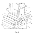
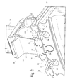
- Figs. 1 and 2 illustrate one technique for preventing axial movement of a turbine bucket received within a slot in a turbine rotor wheel.
- the turbine rotor wheel 10 is formed with a plurality of dovetail slots 12 about the entire outer periphery of the wheel, each dovetail slot 12 receiving a complementary dovetail portion 14 of a bucket or blade 16 (only three complete slots and one bucket shown in the Figures).
- the bucket or blade 16 is of conventional construction, including a shank portion 18, an airfoil portion 20 and the dovetail portion (or simply, dovetail) 14.
- the radially projecting portions 24 of the wheel which define the slots 12 are formed with first lockwire slots 26, each closed at its radially outer end 28 and open at its radially inner end 30.
- the first lockwire slots 26 are formed adjacent to one side of the wheel, and together, form an annular 360° slot about the periphery of the wheel, interrupted by the dovetail slots 12.
- Axially offset portions (or lock tabs) 32 of the bucket dovetails 14 define a plurality of second lockwire slots 34 that are alignable with the first lockwire slots 26 upon introduction of the buckets 16 into the dovetail slots 12.
- a lockwire 36 (preferably a suitable metal alloy) may then be introduced into the aligned lockwire slots 26, 34 with free ends 38, 40 shaped (e.g., reduced to a semi-circular cross section) to smoothly overlap each other along opposed surfaces 39, 41 in a normally-installed condition ( Fig. 3 ), recognizing that the opposed surfaces are substantially flat when the lockwire is uncoiled and arcuate when installed in the annular slots 26, 34.
- the lockwire itself may be a single strand or multiple connected or overlapping segments.
- Axially-oriented retaining pins 42 inserted through the portions 24 of the rotor wheel 10 are employed to hold the lockwire 36 within the lockwire slots 26 ( Figs. 1 and 2 ).
- Fig. 4 illustrates a problem experienced with the lockwire configuration as described above. Specifically, it has been found that the lockwire 36 is prone to circumferential rotation during turbine operation due perhaps to thermal and/or mechanical ratcheting. Resulting separation of the free ends 38, 40 of the lockwire can result in one end (the trailing end in the direction of lockwire rotation) travelling below (i.e., radially inwardly) of one of the pins 42 so that during lockwire rotation in the direction shown by arrow 44, the lockwire 36 may escape the lockwire slots 26, 34, thereby permitting axial movement of the buckets 16 within the dovetail slots 12.
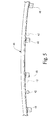
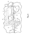
- Figs. 5 and 6 illustrates an exemplary but nonlimiting embodiment of a lockwire 46 (or other equivalent surface feature) provided with radially inwardly extending tabs 48 for substantially preventing excessive circumferential rotation of the lockwire 46 when installed in the lockwire slots 26, 34 ( Fig. 6 ), as described further below.
- the end result is that the inner and outer free ends (similar to free ends 38, 40 in Fig. 3 but not shown in Fig. 5 ), of the lockwire 46 are prevented from excessive circumferential rotation which might otherwise lead to one free end moving below or radially inward of the retaining pins 42 as shown in Fig. 4 .
- the lockwire 46 may have a round cross section with an appropriately chosen diameter, and the free ends 38, 40 are each also reshaped to a smaller cross section (e.g., semi-circular) than the remaining major length of the lockwire to provide an overlap region of substantially the same profile as the remainder of the lockwire, with the free ends engaged along opposed substantially flat, circumferentially (or horizontally)-oriented surfaces as shown in Fig. 3 .
- the opposed surfaces at the overlap may also be wedge-shaped or tapered.
- the ends of the lockwire 46 may also be formed on a slightly larger diameter than the remainder of the lockwire, which is otherwise formed to substantially match the diameter of the lockwire slot. This results in a tighter engagement of the overlapped free ends.
- the lockwire 46 may also be formed with other cross-sectional shapes such as oval, elliptical, sem-circular or other suitable shape.
- the lockwire 46 is provided with at least one and preferably between 2 and 4 or more of the radially extending tabs 48 having thicknesses less than the diameter of the lockwire.
- lockwire diameters of 0.188", 0.250", and 0.300 may have tab thicknesses of substantially half the given diameters.
- the length, width, thickness and shape of the tabs 48 (or other functionally equivalent surface features added to the lockwire) may vary depending on specific applications as dictated by the available space or load carrying capability required by the intended application.
- the size of the tabs 48 (or other surface features) will be the minimum size that performs the desired function, i.e., stopping any undesirable (i.e., excessive) circumferential rotation of the lockwire by engagement of the tabs (or other surface features) with respective, next-adjacent retaining pins 42.
- the anti-rotation tabs 48 are preferably welded or brazed to the lockwire, but the invention is not limited to any particular securement or forming technique.
- the tabs 48 or other surface features may be attached to the lockwire by casting, forging, welding, brazing, or by any other suitable mechanical attachment.
- the tabs may also be in the form of sheet material bent about the lockwire and secured by any of the above techniques.
- the tabs may also be machined or otherwise made integral with the wire.
- the "tab" may also be formed by one or more local deformations in the lockwire. One example is where a bend creates a tab that will engage the pin 42 in a manner similar to the tab 48.
- Fig. 5 shows a retaining pin 42 circumferentially between a pair of radially inwardly extending tabs 48 so that rotation in either direction will be halted when the pin 42 is engaged by one of the tabs 48. While some rotation of the lockwire is permitted to accommodate, for example thermal growth, circumferential rotation beyond predetermined limits is prevented. It is also possible to mount the tabs 48 such that two tabs 48 lie, respectively, on opposite sides of two adjacent pins 42 (see the dotted line pins 42 to the outside of adjacent tabs 48).
- the number of tabs 48 (or other surface features) on the lockwire may vary between one and more than four, but it is preferable (but not required) that the tabs or other surface features be located substantially mid-way between the free ends of the lockwire.
- the pins 42 need not be of the shape illustrated in the drawings.
- Other axially extending surface features on the rotor wheel or in the buckets may be used to engage one or more of the tabs 48 or other surface features on the lockwire to prevent circumferential rotation of the lockwire.
- Fig. 6A is a transparency showing a tab 48A extending radially outwardly of the lockwire 46A, and received in an opening 50 formed in the dovetail portion 52 of the bucket 54.
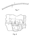
- Fig. 7 illustrates a lockwire 56 provided with one or more axially-extending tabs 58 sized, shaped and located to engage a hole, slot or other surface feature provided in the rotor wheel or bucket.
- FIG 8 shows one example where the lockwire 56 of Fig.7 is installed in the annular groove 60 (shown only with respect to the single bucket 62) such that the axially-extending tab 58 is loosely received within a radially extending slot 64 formed in the bucket dovetail 66 that opens into the annular groove 60. In this way, the lockwire 56 is prevented from excessive circumferential rotation that might otherwise allow escape of the lockwire 56 from the annular slot or groove 60.
- the axially-extending tab (or other surface feature) 58 may also vary in size, shape and number as described above in connection with the tab(s) 48, and that the tab 58 may extend axially from either side of the lockwire depending on the location of a hole, groove, notch or other surface feature within the annular or circumferential slot or groove 60 in the bucket (or turbine wheel) with which it cooperates to prevent circumferential rotation of the lockwire.
Landscapes
- Engineering & Computer Science (AREA)
- Mechanical Engineering (AREA)
- General Engineering & Computer Science (AREA)
- Turbine Rotor Nozzle Sealing (AREA)
Abstract
Description
- The invention relates to a retention system used to prevent axial movement of a turbine bucket dovetail in a corresponding dovetail slot in a turbine rotor wheel, and more specifically, to techniques for preventing circumferential rotation of the axial retention system. This retention system typically takes the form of a lockwire within an annular slot or groove in the turbine rotor wheel.
- In conventional turbine and/or turbine compressor components, buckets (or blades, or airfoils) are held in a rotor wheel by means of a slotted connection, e.g., a so-called "fir tree" or "Christmas tree" arrangement where an inwardly-tapered male connector portion at the radially inner end of the bucket is received in a complementary female slot in the rotor wheel. Such connections are also generically referred to as "dovetail" connections, embracing various complementary shapes which lock the buckets to the wheel in the radial and circumferential directions so as to accommodate the high centrifugal forces generated by rotation of the turbine rotor.
- The fit between the blade dovetail and the dovetail slot is sufficiently loose to allow for assembly and tolerances. Centrifugal loading above a certain threshold speed effectively locks up the bucket in the wheel due to the contact forces and friction. However, operation at low speed, during which the blades are able to rock inside the dovetail, can have the tendency to make the blade move along the dovetail in the absence of axial retention. If the blade is not properly retained, the eventual likely outcome is a collision with neighboring stationary components. Before such collision can take place however, the axial movement along the dovetail could effectively block cooling flow into the blade. In the absence of the cooling flow, oxidation erosion will wear away the leading edge of the blade. An additional consequence, therefore, is unplanned machine down-time and maintenance resulting from varying degrees of machine performance deterioration up to blade separation and resulting collateral or domestic object damage.
- In accordance with usual design practice, the buckets or blades are prevented from moving axially in the dovetail slots provided in the rotor wheel by a retention device, hereafter called a "lockwire", passing through an annular slot formed in the radially outer periphery of the wheel and passing through circumferentially-aligned slots in the dovetail portions of the respective buckets. The free ends of the wire are shaped so that they come together at an overlapped joint, thus allowing for minor changes in length and diameter of the lockwire as the rotor wheel, rotor wheel slots and buckets expand and contract during transient periods. The lockwire is held in place by the radial spring force stemming from installation of a relatively larger-diameter lockwire in a relatively smaller-diameter annular slot, and pins mounted in the turbine wheel, radially inwardly of the lockwire. It has been discovered that rotation of the lockwire within the annular slot in the rotor wheel (which occurs over time) can cause the free ends of the lockwire to separate at the overlap joint so that one end of the lockwire may engage a pin and bend downwardly (radially inwardly) below the pin and, thus permit the lockwire to escape the annular slot.
- Without the lockwire, the airfoils are free to travel axially along the dovetail slots, creating the potential for excessive wear and interference as mentioned above. In addition, this is especially consequential in first and second stage buckets that rely on holes in the base of the bucket to provide internal cooling. When these holes are blocked due to axial movement of the bucket, cooling air cannot reach the target area and the bucket can quickly oxidize along the leading edge.
- There remains a need for a reliable technique for preventing circumferential rotation of the lockwire within its annular slot to thereby prevent escape of the lockwire from the rotor wheel by preventing rotation of the lockwire.
- In one exemplary but nonlimiting embodiment, the invention relates to a retention system for a plurality of turbine buckets located in respective mating slots in a turbine rotor wheel, the retention system comprising a plurality of first circumferentially-oriented retention slots formed in outer peripheral portions of the turbine wheel; a plurality of second circumferentially-oriented retention slots formed in wheel mounting portions of the buckets, the first and second retention slots aligned to form an annular lockwire retention slot; a lockwire located within the annular lockwire retention slot, the lockwire having free ends; a first surface feature on one or both of the turbine rotor wheel and one or more of the plurality of turbine buckets; and a second surface feature on the lockwire adapted to engage with the first surface feature on one or both of the turbine rotor wheel and one or more of the plurality of turbine buckets for preventing circumferential rotation of the lockwire beyond predetermined limits.
- In a second exemplary but nonlimiting embodiment, the invention relates to a retention system for a plurality of turbine buckets located in respective mating slots in a turbine rotor wheel, the retention system comprising a plurality of first circumferentially-oriented retention slots formed in outer peripheral portions of the turbine wheel; a plurality of second circumferentially-oriented retention slots formed in wheel mounting portions of the buckets, the first and second retention slots aligned to form an annular lockwire retention slot; a lockwire located within the annular lockwire retention slot, the lockwire having free ends; at least one axially-oriented surface feature provided on the rotor wheel or on one or more of the plurality of buckets for holding the lockwire in the annular retention slot; and at least one radially extending surface feature on the lockwire engageable with the at least one axially-oriented surface feature for preventing circumferential rotation of the lockwire beyond predetermined limits.
- In still another nonlimiting aspect, the invention relates to a retention system for a plurality of turbine buckets located in respective mating slots in a turbine rotor wheel, the retention system comprising a plurality of first circumferentially-oriented retention slots formed in outer peripheral portions of the turbine wheel; a plurality of second circumferentially-oriented retention slots formed in wheel mounting portions of the buckets, the first and second retention slots aligned to form an annular lockwire retention slot; a lockwire located within the annular lockwire retention slot, the lockwire having free ends; at least one surface feature provided on the rotor wheel or on one or more of the plurality of buckets for holding the lockwire in the annular retention slot; and at least one axially-extending surface feature on the lockwire engageable with the at least one surface feature on the rotor wheel or on one or more of the plurality of buckets for preventing circumferential rotation of the lockwire beyond predetermined limits.
- The invention will now be described in detail in connection with the drawings identified below.
-
-
Fig. 1 is a partial top perspective view of a known turbine rotor wheel and bucket assembly showing a lockwire in place; -
Fig. 2 is a partial bottom perspective view of the rotor wheel and bucket assembly shown inFig. 1 ; -
Fig. 3 is a partial elevation view of overlapped free ends of a lockwire; -
Fig. 4 is a schematic representation of separated free ends of a lockwire, with one end trapped below a retaining pin; -
Fig. 5 is a partial perspective view of an annular lockwire fitted with radially-inwardly extending anti-rotation tabs in accordance with an exemplary but nonlimiting embodiment of the invention; -
Fig. 6 is a partial perspective view of a rotor wheel with the lockwire ofFig. 5 installed; -
Fig. 6A is a partial elevation in transparent format, illustrating an alternative but nonlimiting embodiment where the anti-rotation tabs extend radially outwardly of the lockwire; -
Fig. 7 is a perspective view of a lockwire fitted with axially-extending anti-rotation tabs in accordance with another exemplary but nonlimiting embodiment of the invention; and -
Fig. 8 is a partial perspective view of the lockwire ofFig. 7 installed within a bucket lockwire slot. -
Figs. 1 and2 illustrate one technique for preventing axial movement of a turbine bucket received within a slot in a turbine rotor wheel. More specifically, theturbine rotor wheel 10 is formed with a plurality ofdovetail slots 12 about the entire outer periphery of the wheel, eachdovetail slot 12 receiving acomplementary dovetail portion 14 of a bucket or blade 16 (only three complete slots and one bucket shown in the Figures). It will be understood that the bucket orblade 16 is of conventional construction, including ashank portion 18, anairfoil portion 20 and the dovetail portion (or simply, dovetail) 14. - The radially projecting
portions 24 of the wheel which define theslots 12 are formed withfirst lockwire slots 26, each closed at its radiallyouter end 28 and open at its radiallyinner end 30. Thefirst lockwire slots 26 are formed adjacent to one side of the wheel, and together, form an annular 360° slot about the periphery of the wheel, interrupted by thedovetail slots 12. Axially offset portions (or lock tabs) 32 of thebucket dovetails 14 define a plurality ofsecond lockwire slots 34 that are alignable with thefirst lockwire slots 26 upon introduction of thebuckets 16 into thedovetail slots 12. A lockwire 36 (preferably a suitable metal alloy) may then be introduced into the alignedlockwire slots free ends opposed surfaces Fig. 3 ), recognizing that the opposed surfaces are substantially flat when the lockwire is uncoiled and arcuate when installed in theannular slots retaining pins 42 inserted through theportions 24 of therotor wheel 10 are employed to hold thelockwire 36 within the lockwire slots 26 (Figs. 1 and2 ). -
Fig. 4 illustrates a problem experienced with the lockwire configuration as described above. Specifically, it has been found that thelockwire 36 is prone to circumferential rotation during turbine operation due perhaps to thermal and/or mechanical ratcheting. Resulting separation of thefree ends pins 42 so that during lockwire rotation in the direction shown byarrow 44, thelockwire 36 may escape thelockwire slots buckets 16 within thedovetail slots 12. -
Figs. 5 and6 illustrates an exemplary but nonlimiting embodiment of a lockwire 46 (or other equivalent surface feature) provided with radially inwardly extendingtabs 48 for substantially preventing excessive circumferential rotation of thelockwire 46 when installed in thelockwire slots 26, 34 (Fig. 6 ), as described further below. The end result is that the inner and outer free ends (similar tofree ends Fig. 3 but not shown inFig. 5 ), of thelockwire 46 are prevented from excessive circumferential rotation which might otherwise lead to one free end moving below or radially inward of theretaining pins 42 as shown inFig. 4 . - The
lockwire 46, like thelockwire 36, may have a round cross section with an appropriately chosen diameter, and thefree ends Fig. 3 . The opposed surfaces at the overlap may also be wedge-shaped or tapered. The ends of thelockwire 46 may also be formed on a slightly larger diameter than the remainder of the lockwire, which is otherwise formed to substantially match the diameter of the lockwire slot. This results in a tighter engagement of the overlapped free ends. - The
lockwire 46 may also be formed with other cross-sectional shapes such as oval, elliptical, sem-circular or other suitable shape. - The
lockwire 46 is provided with at least one and preferably between 2 and 4 or more of the radially extendingtabs 48 having thicknesses less than the diameter of the lockwire. For example, lockwire diameters of 0.188", 0.250", and 0.300" may have tab thicknesses of substantially half the given diameters. The length, width, thickness and shape of the tabs 48 (or other functionally equivalent surface features added to the lockwire) may vary depending on specific applications as dictated by the available space or load carrying capability required by the intended application. In most cases, the size of the tabs 48 (or other surface features) will be the minimum size that performs the desired function, i.e., stopping any undesirable (i.e., excessive) circumferential rotation of the lockwire by engagement of the tabs (or other surface features) with respective, next-adjacent retaining pins 42. - The
anti-rotation tabs 48 are preferably welded or brazed to the lockwire, but the invention is not limited to any particular securement or forming technique. For example, thetabs 48 or other surface features may be attached to the lockwire by casting, forging, welding, brazing, or by any other suitable mechanical attachment. The tabs may also be in the form of sheet material bent about the lockwire and secured by any of the above techniques. The tabs may also be machined or otherwise made integral with the wire. The "tab" may also be formed by one or more local deformations in the lockwire. One example is where a bend creates a tab that will engage thepin 42 in a manner similar to thetab 48. In addition, the number and location of the tabs (or other surface features) relative to the retaining pins may vary. For example,Fig. 5 shows a retainingpin 42 circumferentially between a pair of radially inwardly extendingtabs 48 so that rotation in either direction will be halted when thepin 42 is engaged by one of thetabs 48. While some rotation of the lockwire is permitted to accommodate, for example thermal growth, circumferential rotation beyond predetermined limits is prevented. It is also possible to mount thetabs 48 such that twotabs 48 lie, respectively, on opposite sides of two adjacent pins 42 (see the dotted line pins 42 to the outside of adjacent tabs 48). The number of tabs 48 (or other surface features) on the lockwire may vary between one and more than four, but it is preferable (but not required) that the tabs or other surface features be located substantially mid-way between the free ends of the lockwire. In addition, thepins 42 need not be of the shape illustrated in the drawings. Other axially extending surface features on the rotor wheel or in the buckets may be used to engage one or more of thetabs 48 or other surface features on the lockwire to prevent circumferential rotation of the lockwire. - It will be appreciated that the tabs 48 (or other surface features) may also extend radially outwardly of the lockwire, as illustrated, for example, in
Fig. 6A. Fig. 6A is a transparency showing atab 48A extending radially outwardly of thelockwire 46A, and received in anopening 50 formed in thedovetail portion 52 of thebucket 54. - It is also within the scope of the invention to have axially extending tabs or other surface features on the lockwire that, upon minimal rotation of the lockwire, will engage a hole or slot or other surface feature formed in the adj acent slot wall of the bucket or turbine wheel. For example,
Fig. 7 illustrates alockwire 56 provided with one or more axially-extendingtabs 58 sized, shaped and located to engage a hole, slot or other surface feature provided in the rotor wheel or bucket.Fig. 8 shows one example where thelockwire 56 ofFig.7 is installed in the annular groove 60 (shown only with respect to the single bucket 62) such that the axially-extendingtab 58 is loosely received within aradially extending slot 64 formed in thebucket dovetail 66 that opens into theannular groove 60. In this way, thelockwire 56 is prevented from excessive circumferential rotation that might otherwise allow escape of the lockwire 56 from the annular slot orgroove 60. It will be appreciated that the axially-extending tab (or other surface feature) 58 may also vary in size, shape and number as described above in connection with the tab(s) 48, and that thetab 58 may extend axially from either side of the lockwire depending on the location of a hole, groove, notch or other surface feature within the annular or circumferential slot orgroove 60 in the bucket (or turbine wheel) with which it cooperates to prevent circumferential rotation of the lockwire. - In all cases, the amount of lockwire rotation is limited to the extent that separation of the overlapped free ends of the lockwire is precluded.
- Various embodiments of the invention are indicated in the following clauses:
- 1. A retention system for a plurality of turbine buckets located in respective mating slots in a turbine rotor wheel, the retention system comprising:
- a plurality of first circumferentially-oriented retention slots formed in outer peripheral portions of the turbine wheel;
- a plurality of second circumferentially-oriented retention slots formed in wheel mounting portions of said buckets, said first and second retention slots aligned to form an annular lockwire retention slot;
- a lockwire located within said annular lockwire retention slot, said lockwire having free ends;
- a first surface feature on one or both of said turbine rotor wheel and one or more of said plurality of turbine buckets; and
- a second surface feature on said lockwire adapted to engage with said first surface feature on one or both of said turbine rotor wheel and one or more of said plurality of turbine buckets for preventing circumferential rotation of said lockwire beyond predetermined limits.
- 2. The retention system of clause 1 wherein said first surface feature on one or both of said turbine rotor wheel and one or more of said plurality of turbine buckets comprises a plurality of axially-extending pins.
- 3. The retention system of either of clause 1 or 2 wherein said second surface feature on said lockwire comprises at least one axially-extending tab.
- 4. The retention system of clause 3 wherein said at least one axially-extending tab is attached to, or made integral with said lockwire.
- 5. The retention system of any of the preceding clauses wherein said second surface feature on said lockwire comprises at least one radially-extending tab.
- 6. The retention system of clauses 1 wherein said second surface feature on said lockwire comprises at least one anti rotation element attached to said lockwire.
- 7. A retention system for a plurality of turbine buckets located in respective mating slots in a turbine rotor wheel, the retention system comprising:
- a plurality of first circumferentially-oriented retention slots formed in outer peripheral portions of the turbine wheel;
- a plurality of second circumferentially-oriented retention slots formed in wheel mounting portions of said buckets, said first and second retention slots aligned to form an annular lockwire retention slot;
- a lockwire located within said annular lockwire retention slot, said lockwire having free ends;
- at least one axially-oriented surface feature provided on said rotor wheel or on one or more of said plurality of buckets for holding said lockwire in said annular retention slot; and
- at least one radially extending surface feature on said lockwire engageable with said at least one axially-oriented surface feature for preventing circumferential rotation of said lockwire beyond predetermined limits.
- 8. The retention system according to clause 7, wherein said at least one axially-oriented surface feature comprise a plurality of circumferentially-spaced pins.
- 9. The retention system according to clause 8, wherein said at least one radially extending surface feature comprises one or more anti-rotation tabs extending substantially radially inwardly or outwardly from said lockwire.
- 10. The retention system according to either of clause 7 or 8 wherein said at least one radially extending surface feature is formed by a local deformation of said lockwire.
- 11. The retention system of any one of clauses 7 to 10 wherein said lockwire has a substantially circular cross section and wherein said least one radially-extending surface feature has a thickness dimension less than a diameter of said lockwire.
- 12. The retention system according to any one of clauses 7 to 11 wherein, when installed, said free ends of said lockwire overlap, and wherein said at least one radially extending surface feature is located substantially mid-way between said free ends.
- 13. The retention system of clause 7 wherein said at least one radially-extending surface feature is attached to, or made integral with said lockwire.
- 14. A retention system for a plurality of turbine buckets located in respective mating slots in a turbine rotor wheel, the retention system comprising:
- a plurality of first circumferentially-oriented retention slots formed in outer peripheral portions of the turbine wheel;
- a plurality of second circumferentially-oriented retention slots formed in wheel mounting portions of said buckets, said first and second retention slots aligned to form an annular lockwire retention slot;
- a lockwire located within said annular lockwire retention slot, said lockwire having free ends;
- at least one surface feature provided on said rotor wheel or on one or more of said plurality of buckets for holding said lockwire in said annular retention slot; and
- at least one axially-extending surface feature on said lockwire engageable with said at least one surface feature on said rotor wheel or on one or more of said plurality of buckets for preventing circumferential rotation of said lockwire beyond predetermined limits.
- 15. The retention system according to
clause 14 wherein said at least one axially-extending surface feature on said lockwire comprises one or more tabs extending axially in a direction away from said turbine rotor wheel. - 16. The retention system of either of
clause 14 to 15 wherein said at least one axially-extending surface feature is attached to, or made integral with said lockwire. - 17. The retention system according to
clause 14, wherein said at least one axially-extending surface feature comprises one or more anti-rotation tabs extending substantially axially from said lockwire. - 18. The retention system according to clause 17 wherein said at least one surface feature provided on said rotor wheel or on one or more of said plurality of buckets comprises at least one radially oriented slot.
- 19. The retention system of any one of
clauses 14 to 18 wherein said lockwire has a substantially circular cross section and wherein said least one axially-extending surface feature has a thickness dimension less than a diameter of said lockwire. - 20. The retention system according to any one of
clauses 14 to 19 wherein, when installed, said free ends of said lockwire overlap.
Claims (15)
- A retention system for a plurality of turbine buckets (16) located in respective mating slots (12) in a turbine rotor wheel (10), the retention system comprising:a plurality of first circumferentially-oriented retention slots (26) formed in outer peripheral portions (24) of the turbine wheel;a plurality of second circumferentially-oriented retention slots (34) formed in wheel mounting portions (32) of said buckets, said first and second retention slots aligned to form an annular lockwire retention slot;a lockwire (46,46A,56) located within said annular lockwire retention slot, said lockwire having free ends (38,40);a first surface feature (42) on one or both of said turbine rotor wheel and one or more of said plurality of turbine buckets; anda second surface feature (48,48A,58) on said lockwire adapted to engage with said first surface feature on one or both of said turbine rotor wheel and one or more of said plurality of turbine buckets for preventing circumferential rotation of said lockwire beyond predetermined limits.
- The retention system of claim 1, wherein said first surface feature on one or both of said turbine rotor wheel (10) and one or more of said plurality of turbine buckets (16) comprises a plurality of axially-extending pins (42).
- The retention system of either one of claim 1 or 2, wherein said second surface feature on said lockwire (56) comprises at least one axially-extending tab (58).
- The retention system of claim 3, wherein said at least one axially-extending tab (58) is attached to, or made integral with said lockwire (56).
- The retention system of any one of the preceding claims, wherein said second surface feature on said lockwire comprises at least one radially-extending tab (48,48A).
- The retention system of claim 1 wherein said second surface feature on said lockwire comprises at least one anti rotation element (48,48A,58) attached to said lockwire.
- The retention system of claim 1, wherein:said first surface feature is comprised as at least one axially-oriented surface feature (42) provided on said rotor wheel (10) or on one or more of said plurality of buckets (16) for holding said lockwire (46,46A) in said annular retention slot; andsaid second surface feature is comprised as at least one radially extending surface feature (48,48A) on said lockwire engageable with said at least one axially-oriented surface feature for preventing circumferential rotation of said lockwire beyond predetermined limits.
- The retention system according to claim 7, wherein said at least one axially-oriented surface feature comprises a plurality of circumferentially-spaced pins (42).
- The retention system according to claim 8, wherein said at least one radially extending surface feature comprises one or more anti-rotation tabs (48,48A) extending substantially radially inwardly or outwardly from said lockwire (46,46A).
- The retention system according to either of claim 7 or 8, wherein said at least one radially extending surface feature is formed by a local deformation of said lockwire (46,46A).
- The retention system of any one of claims 7 to 10, wherein said lockwire (46,46A) has a substantially circular cross section and wherein said least one radially-extending surface feature (48,48A) has a thickness dimension less than a diameter of said lockwire.
- The retention system according to any one of claims 7 to 11, wherein, when installed, said free ends (38,40) of said lockwire overlap (46,46A), and wherein said at least one radially extending surface feature (48,48A) is located substantially mid-way between said free ends.
- The retention system of claim 1, wherein:said first surface feature is comprised as at least one surface feature provided on said rotor wheel (10) or on one or more of said plurality of buckets (16) for holding said lockwire (56) in said annular retention slot; andsaid second surface feature is comprises as at least one axially-extending surface feature (58) on said lockwire engageable with said at least one surface feature on said rotor wheel or on one or more of said plurality of buckets (16) for preventing circumferential rotation of said lockwire beyond predetermined limits.
- The retention system according to claim 13 wherein said at least one axially-extending surface feature on said lockwire comprises one or more tabs (58) extending axially in a direction away from said turbine rotor wheel (10).
- The retention system of either of claim 13 or 14, wherein said at least one axially-extending surface feature is attached to, or made integral with said lockwire (56).
Applications Claiming Priority (1)
| Application Number | Priority Date | Filing Date | Title |
|---|---|---|---|
| US12/899,305 US8905717B2 (en) | 2010-10-06 | 2010-10-06 | Turbine bucket lockwire rotation prevention |
Publications (3)
| Publication Number | Publication Date |
|---|---|
| EP2439378A2 true EP2439378A2 (en) | 2012-04-11 |
| EP2439378A3 EP2439378A3 (en) | 2014-08-13 |
| EP2439378B1 EP2439378B1 (en) | 2018-10-03 |
Family
ID=44992535
Family Applications (1)
| Application Number | Title | Priority Date | Filing Date |
|---|---|---|---|
| EP11183738.1A Active EP2439378B1 (en) | 2010-10-06 | 2011-10-03 | Turbine bucket lockwire rotation prevention |
Country Status (2)
| Country | Link |
|---|---|
| US (1) | US8905717B2 (en) |
| EP (1) | EP2439378B1 (en) |
Cited By (6)
| Publication number | Priority date | Publication date | Assignee | Title |
|---|---|---|---|---|
| EP3211180A1 (en) * | 2016-02-23 | 2017-08-30 | PW Power Systems, Inc. | Turbine bucket lockwire anti-rotation device for gas turbine engine |
| EP3293358A1 (en) * | 2016-09-08 | 2018-03-14 | United Technologies Corporation | Airfoil retention assembly for a gas turbine engine |
| WO2018093473A1 (en) * | 2016-11-18 | 2018-05-24 | General Electric Company | Turbomachine bucket with radial support, shim and related turbomachine rotor |
| US11555407B2 (en) | 2020-05-19 | 2023-01-17 | General Electric Company | Turbomachine rotor assembly |
| EP4130440A1 (en) * | 2021-08-03 | 2023-02-08 | Garrett Transportation I Inc. | Turbocharger control with overspeed protection |
| EP4722494A1 (en) * | 2024-10-02 | 2026-04-08 | GE Vernova Technology GmbH | Systems and methods for servicing a turbomachine |
Families Citing this family (5)
| Publication number | Priority date | Publication date | Assignee | Title |
|---|---|---|---|---|
| US20130323052A1 (en) * | 2012-05-31 | 2013-12-05 | Solar Turbines Inc. | Retaining ring |
| EP3685019B1 (en) * | 2017-09-20 | 2025-05-28 | Sulzer Turbo Services Venlo B.V. | Assembly of vane units |
| US20200131916A1 (en) * | 2018-10-31 | 2020-04-30 | United Technologies Corporation | Turbine blade assembly |
| GB2584097A (en) * | 2019-05-20 | 2020-11-25 | Cross Mfg 1938 Limited | Ring fastener |
| JP7213835B2 (en) * | 2020-02-10 | 2023-01-27 | 三菱重工業株式会社 | turbine wheel |
Family Cites Families (31)
| Publication number | Priority date | Publication date | Assignee | Title |
|---|---|---|---|---|
| US2713991A (en) | 1951-05-05 | 1955-07-26 | A V Roe Canada Ltd | Rotor blade locking device |
| US2873088A (en) * | 1953-05-21 | 1959-02-10 | Gen Electric | Lightweight rotor construction |
| US2890069A (en) | 1956-04-10 | 1959-06-09 | Gen Motors Corp | Rotary seal |
| US2971743A (en) | 1957-08-14 | 1961-02-14 | Gen Motors Corp | Interlocked blade shrouding |
| US3076634A (en) | 1959-06-12 | 1963-02-05 | Ass Elect Ind | Locking means for compressor and turbine blades |
| GB894704A (en) | 1960-03-30 | 1962-04-26 | Gen Electric | Improvements in reusable locking means for turbine or compressor rotor assemblies |
| US3383095A (en) | 1967-09-12 | 1968-05-14 | Gen Electric | Lock for turbomachinery blades |
| US3632228A (en) | 1970-07-29 | 1972-01-04 | Gen Electric | Device for locking turbomachinery blades |
| US3832092A (en) | 1973-10-19 | 1974-08-27 | Gen Electric | Device for locking turbomachinery blades |
| US3936234A (en) | 1975-02-10 | 1976-02-03 | General Electric Company | Device for locking turbomachinery blades |
| US4221542A (en) * | 1977-12-27 | 1980-09-09 | General Electric Company | Segmented blade retainer |
| GB2042652B (en) | 1979-02-21 | 1983-07-20 | Rolls Royce | Joint making packing |
| US4349318A (en) | 1980-01-04 | 1982-09-14 | Avco Corporation | Boltless blade retainer for a turbine wheel |
| US4566857A (en) * | 1980-12-19 | 1986-01-28 | United Technologies Corporation | Locking of rotor blades on a rotor disk |
| US4470757A (en) | 1982-02-25 | 1984-09-11 | United Technologies Corporation | Sideplate retention for a turbine rotor |
| FR2524932A1 (en) | 1982-04-08 | 1983-10-14 | Snecma | DEVICE FOR AXIAL RETENTION OF BLADE FEET IN A TURBOMACHINE DISC |
| FR2524933B1 (en) | 1982-04-13 | 1987-02-20 | Snecma | AXIAL LOCKING DEVICE FOR TURBINE OR COMPRESSOR ROTOR BLADES |
| US4778342A (en) | 1985-07-24 | 1988-10-18 | Imo Delaval, Inc. | Turbine blade retainer |
| US4797065A (en) | 1986-10-17 | 1989-01-10 | Transamerica Delaval Inc. | Turbine blade retainer |
| US5302086A (en) | 1992-08-18 | 1994-04-12 | General Electric Company | Apparatus for retaining rotor blades |
| US5281098A (en) | 1992-10-28 | 1994-01-25 | General Electric Company | Single ring blade retaining assembly |
| FR2729709A1 (en) | 1995-01-25 | 1996-07-26 | Snecma | Turbine rotor seal and retainer |
| DE19516694C2 (en) | 1995-05-06 | 2001-06-28 | Mtu Aero Engines Gmbh | Device for fixing blades to the impeller, in particular a turbine of a gas turbine engine |
| US5984639A (en) | 1998-07-09 | 1999-11-16 | Pratt & Whitney Canada Inc. | Blade retention apparatus for gas turbine rotor |
| DE19960896A1 (en) | 1999-12-17 | 2001-06-28 | Rolls Royce Deutschland | Retaining device for rotor blades of axial turbine engine, with recesses in outer circumference of retainer corresponding to sections of blade receivers |
| DE10128505C2 (en) | 2001-06-14 | 2003-04-30 | Mtu Aero Engines Gmbh | Attachment of blades |
| US7264448B2 (en) | 2004-10-06 | 2007-09-04 | Siemens Power Corporation, Inc. | Remotely accessible locking system for turbine blades |
| EP1840338B1 (en) | 2006-03-28 | 2011-08-17 | Siemens Aktiengesellschaft | Arrangement for axial locking of turbine blades in a rotor and gas turbine with such an arrangement |
| DE102006054154B4 (en) | 2006-11-16 | 2014-03-13 | Man Diesel & Turbo Se | turbocharger |
| US8210823B2 (en) * | 2008-07-08 | 2012-07-03 | General Electric Company | Method and apparatus for creating seal slots for turbine components |
| FR2939832B1 (en) | 2008-12-11 | 2011-01-07 | Turbomeca | TURBINE WHEEL EQUIPPED WITH AXIAL HOLDING DEVICE LOCKING BLADES WITH RESPECT TO A DISK. |
-
2010
- 2010-10-06 US US12/899,305 patent/US8905717B2/en active Active
-
2011
- 2011-10-03 EP EP11183738.1A patent/EP2439378B1/en active Active
Non-Patent Citations (1)
| Title |
|---|
| None |
Cited By (10)
| Publication number | Priority date | Publication date | Assignee | Title |
|---|---|---|---|---|
| EP3211180A1 (en) * | 2016-02-23 | 2017-08-30 | PW Power Systems, Inc. | Turbine bucket lockwire anti-rotation device for gas turbine engine |
| US10145249B2 (en) | 2016-02-23 | 2018-12-04 | Mechanical Dynamics & Analysis Llc | Turbine bucket lockwire anti-rotation device for gas turbine engine |
| EP3293358A1 (en) * | 2016-09-08 | 2018-03-14 | United Technologies Corporation | Airfoil retention assembly for a gas turbine engine |
| US10415401B2 (en) | 2016-09-08 | 2019-09-17 | United Technologies Corporation | Airfoil retention assembly for a gas turbine engine |
| WO2018093473A1 (en) * | 2016-11-18 | 2018-05-24 | General Electric Company | Turbomachine bucket with radial support, shim and related turbomachine rotor |
| CN110177920A (en) * | 2016-11-18 | 2019-08-27 | 通用电气公司 | Turbine bucket, gasket and relevant turbine rotor with radial support |
| US10400614B2 (en) | 2016-11-18 | 2019-09-03 | General Electric Company | Turbomachine bucket with radial support, shim and related turbomachine rotor |
| US11555407B2 (en) | 2020-05-19 | 2023-01-17 | General Electric Company | Turbomachine rotor assembly |
| EP4130440A1 (en) * | 2021-08-03 | 2023-02-08 | Garrett Transportation I Inc. | Turbocharger control with overspeed protection |
| EP4722494A1 (en) * | 2024-10-02 | 2026-04-08 | GE Vernova Technology GmbH | Systems and methods for servicing a turbomachine |
Also Published As
| Publication number | Publication date |
|---|---|
| EP2439378B1 (en) | 2018-10-03 |
| EP2439378A3 (en) | 2014-08-13 |
| US8905717B2 (en) | 2014-12-09 |
| US20120087798A1 (en) | 2012-04-12 |
Similar Documents
| Publication | Publication Date | Title |
|---|---|---|
| EP2439378B1 (en) | Turbine bucket lockwire rotation prevention | |
| US8485784B2 (en) | Turbine bucket lockwire rotation prevention | |
| EP2149674B1 (en) | Bladed turbine rotor with vibration damper | |
| EP2660426B1 (en) | Turbine assembly | |
| US6860722B2 (en) | Snap on blade shim | |
| EP3441638B1 (en) | Rivet-less rotor clip design | |
| EP2505785B1 (en) | Seal assembly for a blade dovetail and corresponding sealing method | |
| US10125635B2 (en) | Fixture and method for installing turbine buckets | |
| US8591192B2 (en) | Turbomachine rotor assembly and method | |
| US3479009A (en) | Blade retainer | |
| JP4820695B2 (en) | Method and system for assembling turbine bucket with shroud and tangential insertion dovetail | |
| US20120034086A1 (en) | Swing axial entry dovetail for steam turbine buckets | |
| EP0710766A1 (en) | Integral disc seal | |
| US7832988B2 (en) | Turbine blade | |
| US6755618B2 (en) | Steam turbine closure bucket attachment | |
| US12372000B2 (en) | Foil, rotor blade, assembly for a turbomachine rotor and rotor | |
| GB2398843A (en) | Rotor wheel assembly with dovetail root arrangement | |
| CN102459819B (en) | A rotor blade for an axial flow turbomachine and mounting for such a rotor blade | |
| US8215915B2 (en) | Blade closing key system for a turbine engine | |
| US6428279B1 (en) | Low windage loss, light weight closure bucket design and related method | |
| US20170356293A1 (en) | Balancing weight for a rotor blade of a turbine stage | |
| EP2540964B1 (en) | System and method for supporting a nozzle assembly | |
| JP2011074806A (en) | Fixing structure of turbine moving blade | |
| JPS61129403A (en) | Coupling device of turbine moving blade |
Legal Events
| Date | Code | Title | Description |
|---|---|---|---|
| AK | Designated contracting states |
Kind code of ref document: A2 Designated state(s): AL AT BE BG CH CY CZ DE DK EE ES FI FR GB GR HR HU IE IS IT LI LT LU LV MC MK MT NL NO PL PT RO RS SE SI SK SM TR |
|
| AX | Request for extension of the european patent |
Extension state: BA ME |
|
| PUAI | Public reference made under article 153(3) epc to a published international application that has entered the european phase |
Free format text: ORIGINAL CODE: 0009012 |
|
| REG | Reference to a national code |
Ref country code: DE Ref legal event code: R079 Ref document number: 602011052505 Country of ref document: DE Free format text: PREVIOUS MAIN CLASS: F01D0005300000 Ipc: F01D0005320000 |
|
| PUAL | Search report despatched |
Free format text: ORIGINAL CODE: 0009013 |
|
| AK | Designated contracting states |
Kind code of ref document: A3 Designated state(s): AL AT BE BG CH CY CZ DE DK EE ES FI FR GB GR HR HU IE IS IT LI LT LU LV MC MK MT NL NO PL PT RO RS SE SI SK SM TR |
|
| AX | Request for extension of the european patent |
Extension state: BA ME |
|
| RIC1 | Information provided on ipc code assigned before grant |
Ipc: F01D 5/32 20060101AFI20140709BHEP |
|
| 17P | Request for examination filed |
Effective date: 20150213 |
|
| RBV | Designated contracting states (corrected) |
Designated state(s): AL AT BE BG CH CY CZ DE DK EE ES FI FR GB GR HR HU IE IS IT LI LT LU LV MC MK MT NL NO PL PT RO RS SE SI SK SM TR |
|
| GRAP | Despatch of communication of intention to grant a patent |
Free format text: ORIGINAL CODE: EPIDOSNIGR1 |
|
| INTG | Intention to grant announced |
Effective date: 20180531 |
|
| RIN1 | Information on inventor provided before grant (corrected) |
Inventor name: AMMANN, LUKE JOHN Inventor name: MYERS, MELBOURNE JAMES Inventor name: XU, LIMING Inventor name: JACALA, ARIEL CAESAR PREPENA Inventor name: ROMAN-MORALES, FELIPE Inventor name: BRUCE, KEVIN LEON |
|
| GRAS | Grant fee paid |
Free format text: ORIGINAL CODE: EPIDOSNIGR3 |
|
| GRAA | (expected) grant |
Free format text: ORIGINAL CODE: 0009210 |
|
| AK | Designated contracting states |
Kind code of ref document: B1 Designated state(s): AL AT BE BG CH CY CZ DE DK EE ES FI FR GB GR HR HU IE IS IT LI LT LU LV MC MK MT NL NO PL PT RO RS SE SI SK SM TR |
|
| REG | Reference to a national code |
Ref country code: GB Ref legal event code: FG4D |
|
| REG | Reference to a national code |
Ref country code: CH Ref legal event code: EP Ref country code: AT Ref legal event code: REF Ref document number: 1048812 Country of ref document: AT Kind code of ref document: T Effective date: 20181015 |
|
| REG | Reference to a national code |
Ref country code: DE Ref legal event code: R096 Ref document number: 602011052505 Country of ref document: DE |
|
| REG | Reference to a national code |
Ref country code: IE Ref legal event code: FG4D |
|
| REG | Reference to a national code |
Ref country code: NL Ref legal event code: MP Effective date: 20181003 |
|
| REG | Reference to a national code |
Ref country code: LT Ref legal event code: MG4D |
|
| REG | Reference to a national code |
Ref country code: AT Ref legal event code: MK05 Ref document number: 1048812 Country of ref document: AT Kind code of ref document: T Effective date: 20181003 |
|
| PG25 | Lapsed in a contracting state [announced via postgrant information from national office to epo] |
Ref country code: NL Free format text: LAPSE BECAUSE OF FAILURE TO SUBMIT A TRANSLATION OF THE DESCRIPTION OR TO PAY THE FEE WITHIN THE PRESCRIBED TIME-LIMIT Effective date: 20181003 |
|
| PG25 | Lapsed in a contracting state [announced via postgrant information from national office to epo] |
Ref country code: BG Free format text: LAPSE BECAUSE OF FAILURE TO SUBMIT A TRANSLATION OF THE DESCRIPTION OR TO PAY THE FEE WITHIN THE PRESCRIBED TIME-LIMIT Effective date: 20190103 Ref country code: NO Free format text: LAPSE BECAUSE OF FAILURE TO SUBMIT A TRANSLATION OF THE DESCRIPTION OR TO PAY THE FEE WITHIN THE PRESCRIBED TIME-LIMIT Effective date: 20190103 Ref country code: PL Free format text: LAPSE BECAUSE OF FAILURE TO SUBMIT A TRANSLATION OF THE DESCRIPTION OR TO PAY THE FEE WITHIN THE PRESCRIBED TIME-LIMIT Effective date: 20181003 Ref country code: IS Free format text: LAPSE BECAUSE OF FAILURE TO SUBMIT A TRANSLATION OF THE DESCRIPTION OR TO PAY THE FEE WITHIN THE PRESCRIBED TIME-LIMIT Effective date: 20190203 Ref country code: HR Free format text: LAPSE BECAUSE OF FAILURE TO SUBMIT A TRANSLATION OF THE DESCRIPTION OR TO PAY THE FEE WITHIN THE PRESCRIBED TIME-LIMIT Effective date: 20181003 Ref country code: CZ Free format text: LAPSE BECAUSE OF FAILURE TO SUBMIT A TRANSLATION OF THE DESCRIPTION OR TO PAY THE FEE WITHIN THE PRESCRIBED TIME-LIMIT Effective date: 20181003 Ref country code: ES Free format text: LAPSE BECAUSE OF FAILURE TO SUBMIT A TRANSLATION OF THE DESCRIPTION OR TO PAY THE FEE WITHIN THE PRESCRIBED TIME-LIMIT Effective date: 20181003 Ref country code: LT Free format text: LAPSE BECAUSE OF FAILURE TO SUBMIT A TRANSLATION OF THE DESCRIPTION OR TO PAY THE FEE WITHIN THE PRESCRIBED TIME-LIMIT Effective date: 20181003 Ref country code: LV Free format text: LAPSE BECAUSE OF FAILURE TO SUBMIT A TRANSLATION OF THE DESCRIPTION OR TO PAY THE FEE WITHIN THE PRESCRIBED TIME-LIMIT Effective date: 20181003 Ref country code: AT Free format text: LAPSE BECAUSE OF FAILURE TO SUBMIT A TRANSLATION OF THE DESCRIPTION OR TO PAY THE FEE WITHIN THE PRESCRIBED TIME-LIMIT Effective date: 20181003 Ref country code: FI Free format text: LAPSE BECAUSE OF FAILURE TO SUBMIT A TRANSLATION OF THE DESCRIPTION OR TO PAY THE FEE WITHIN THE PRESCRIBED TIME-LIMIT Effective date: 20181003 |
|
| PG25 | Lapsed in a contracting state [announced via postgrant information from national office to epo] |
Ref country code: AL Free format text: LAPSE BECAUSE OF FAILURE TO SUBMIT A TRANSLATION OF THE DESCRIPTION OR TO PAY THE FEE WITHIN THE PRESCRIBED TIME-LIMIT Effective date: 20181003 Ref country code: RS Free format text: LAPSE BECAUSE OF FAILURE TO SUBMIT A TRANSLATION OF THE DESCRIPTION OR TO PAY THE FEE WITHIN THE PRESCRIBED TIME-LIMIT Effective date: 20181003 Ref country code: SE Free format text: LAPSE BECAUSE OF FAILURE TO SUBMIT A TRANSLATION OF THE DESCRIPTION OR TO PAY THE FEE WITHIN THE PRESCRIBED TIME-LIMIT Effective date: 20181003 Ref country code: GR Free format text: LAPSE BECAUSE OF FAILURE TO SUBMIT A TRANSLATION OF THE DESCRIPTION OR TO PAY THE FEE WITHIN THE PRESCRIBED TIME-LIMIT Effective date: 20190104 Ref country code: PT Free format text: LAPSE BECAUSE OF FAILURE TO SUBMIT A TRANSLATION OF THE DESCRIPTION OR TO PAY THE FEE WITHIN THE PRESCRIBED TIME-LIMIT Effective date: 20190203 |
|
| REG | Reference to a national code |
Ref country code: CH Ref legal event code: PL |
|
| REG | Reference to a national code |
Ref country code: BE Ref legal event code: MM Effective date: 20181031 |
|
| PG25 | Lapsed in a contracting state [announced via postgrant information from national office to epo] |
Ref country code: LU Free format text: LAPSE BECAUSE OF NON-PAYMENT OF DUE FEES Effective date: 20181003 |
|
| REG | Reference to a national code |
Ref country code: DE Ref legal event code: R097 Ref document number: 602011052505 Country of ref document: DE |
|
| REG | Reference to a national code |
Ref country code: IE Ref legal event code: MM4A |
|
| PG25 | Lapsed in a contracting state [announced via postgrant information from national office to epo] |
Ref country code: DK Free format text: LAPSE BECAUSE OF FAILURE TO SUBMIT A TRANSLATION OF THE DESCRIPTION OR TO PAY THE FEE WITHIN THE PRESCRIBED TIME-LIMIT Effective date: 20181003 |
|
| PLBE | No opposition filed within time limit |
Free format text: ORIGINAL CODE: 0009261 |
|
| STAA | Information on the status of an ep patent application or granted ep patent |
Free format text: STATUS: NO OPPOSITION FILED WITHIN TIME LIMIT |
|
| PG25 | Lapsed in a contracting state [announced via postgrant information from national office to epo] |
Ref country code: MC Free format text: LAPSE BECAUSE OF FAILURE TO SUBMIT A TRANSLATION OF THE DESCRIPTION OR TO PAY THE FEE WITHIN THE PRESCRIBED TIME-LIMIT Effective date: 20181003 Ref country code: LI Free format text: LAPSE BECAUSE OF NON-PAYMENT OF DUE FEES Effective date: 20181031 Ref country code: BE Free format text: LAPSE BECAUSE OF NON-PAYMENT OF DUE FEES Effective date: 20181031 Ref country code: CH Free format text: LAPSE BECAUSE OF NON-PAYMENT OF DUE FEES Effective date: 20181031 Ref country code: RO Free format text: LAPSE BECAUSE OF FAILURE TO SUBMIT A TRANSLATION OF THE DESCRIPTION OR TO PAY THE FEE WITHIN THE PRESCRIBED TIME-LIMIT Effective date: 20181003 Ref country code: SK Free format text: LAPSE BECAUSE OF FAILURE TO SUBMIT A TRANSLATION OF THE DESCRIPTION OR TO PAY THE FEE WITHIN THE PRESCRIBED TIME-LIMIT Effective date: 20181003 Ref country code: EE Free format text: LAPSE BECAUSE OF FAILURE TO SUBMIT A TRANSLATION OF THE DESCRIPTION OR TO PAY THE FEE WITHIN THE PRESCRIBED TIME-LIMIT Effective date: 20181003 Ref country code: SM Free format text: LAPSE BECAUSE OF FAILURE TO SUBMIT A TRANSLATION OF THE DESCRIPTION OR TO PAY THE FEE WITHIN THE PRESCRIBED TIME-LIMIT Effective date: 20181003 |
|
| 26N | No opposition filed |
Effective date: 20190704 |
|
| PG25 | Lapsed in a contracting state [announced via postgrant information from national office to epo] |
Ref country code: IE Free format text: LAPSE BECAUSE OF NON-PAYMENT OF DUE FEES Effective date: 20181003 Ref country code: SI Free format text: LAPSE BECAUSE OF FAILURE TO SUBMIT A TRANSLATION OF THE DESCRIPTION OR TO PAY THE FEE WITHIN THE PRESCRIBED TIME-LIMIT Effective date: 20181003 Ref country code: FR Free format text: LAPSE BECAUSE OF NON-PAYMENT OF DUE FEES Effective date: 20181203 |
|
| PG25 | Lapsed in a contracting state [announced via postgrant information from national office to epo] |
Ref country code: MT Free format text: LAPSE BECAUSE OF NON-PAYMENT OF DUE FEES Effective date: 20181003 |
|
| PG25 | Lapsed in a contracting state [announced via postgrant information from national office to epo] |
Ref country code: TR Free format text: LAPSE BECAUSE OF FAILURE TO SUBMIT A TRANSLATION OF THE DESCRIPTION OR TO PAY THE FEE WITHIN THE PRESCRIBED TIME-LIMIT Effective date: 20181003 |
|
| PG25 | Lapsed in a contracting state [announced via postgrant information from national office to epo] |
Ref country code: CY Free format text: LAPSE BECAUSE OF FAILURE TO SUBMIT A TRANSLATION OF THE DESCRIPTION OR TO PAY THE FEE WITHIN THE PRESCRIBED TIME-LIMIT Effective date: 20181003 Ref country code: HU Free format text: LAPSE BECAUSE OF FAILURE TO SUBMIT A TRANSLATION OF THE DESCRIPTION OR TO PAY THE FEE WITHIN THE PRESCRIBED TIME-LIMIT; INVALID AB INITIO Effective date: 20111003 Ref country code: MK Free format text: LAPSE BECAUSE OF NON-PAYMENT OF DUE FEES Effective date: 20181003 |
|
| P01 | Opt-out of the competence of the unified patent court (upc) registered |
Effective date: 20230522 |
|
| REG | Reference to a national code |
Ref country code: DE Ref legal event code: R081 Ref document number: 602011052505 Country of ref document: DE Owner name: GENERAL ELECTRIC TECHNOLOGY GMBH, CH Free format text: FORMER OWNER: GENERAL ELECTRIC COMPANY, SCHENECTADY, NY, US |
|
| REG | Reference to a national code |
Ref country code: GB Ref legal event code: 732E Free format text: REGISTERED BETWEEN 20240222 AND 20240228 |
|
| PGFP | Annual fee paid to national office [announced via postgrant information from national office to epo] |
Ref country code: IT Payment date: 20250923 Year of fee payment: 15 |
|
| PGFP | Annual fee paid to national office [announced via postgrant information from national office to epo] |
Ref country code: GB Payment date: 20250923 Year of fee payment: 15 |
|
| PGFP | Annual fee paid to national office [announced via postgrant information from national office to epo] |
Ref country code: DE Payment date: 20250923 Year of fee payment: 15 |