EP2439084A1 - A pneumatic tire with a knitted fabric as reinforcing structure - Google Patents
A pneumatic tire with a knitted fabric as reinforcing structure Download PDFInfo
- Publication number
- EP2439084A1 EP2439084A1 EP11183926A EP11183926A EP2439084A1 EP 2439084 A1 EP2439084 A1 EP 2439084A1 EP 11183926 A EP11183926 A EP 11183926A EP 11183926 A EP11183926 A EP 11183926A EP 2439084 A1 EP2439084 A1 EP 2439084A1
- Authority
- EP
- European Patent Office
- Prior art keywords
- yarns
- pneumatic tire
- tire
- flipper
- bead
- Prior art date
- Legal status (The legal status is an assumption and is not a legal conclusion. Google has not performed a legal analysis and makes no representation as to the accuracy of the status listed.)
- Granted
Links
- 239000004744 fabric Substances 0.000 title claims abstract description 52
- 230000003014 reinforcing effect Effects 0.000 title claims abstract description 21
- 239000011324 bead Substances 0.000 claims description 64
- 239000000463 material Substances 0.000 claims description 23
- 229920001971 elastomer Polymers 0.000 claims description 17
- 239000005060 rubber Substances 0.000 claims description 17
- 239000000835 fiber Substances 0.000 claims description 15
- 229920000297 Rayon Polymers 0.000 claims description 9
- 238000010276 construction Methods 0.000 claims description 9
- 239000002964 rayon Substances 0.000 claims description 9
- 239000002318 adhesion promoter Substances 0.000 claims description 4
- 210000000006 pectoral fin Anatomy 0.000 description 54
- 239000000945 filler Substances 0.000 description 6
- 238000000926 separation method Methods 0.000 description 6
- 229920001778 nylon Polymers 0.000 description 5
- 229920000728 polyester Polymers 0.000 description 5
- 238000010008 shearing Methods 0.000 description 5
- 239000004677 Nylon Substances 0.000 description 4
- 239000002184 metal Substances 0.000 description 4
- 238000000034 method Methods 0.000 description 4
- 229920000742 Cotton Polymers 0.000 description 3
- 239000004760 aramid Substances 0.000 description 3
- 229920006231 aramid fiber Polymers 0.000 description 3
- 229920003235 aromatic polyamide Polymers 0.000 description 3
- 230000015572 biosynthetic process Effects 0.000 description 3
- 239000002657 fibrous material Substances 0.000 description 3
- 230000000704 physical effect Effects 0.000 description 3
- 230000002787 reinforcement Effects 0.000 description 3
- 239000004753 textile Substances 0.000 description 3
- 241000208202 Linaceae Species 0.000 description 2
- 235000004431 Linum usitatissimum Nutrition 0.000 description 2
- 239000004952 Polyamide Substances 0.000 description 2
- VYPSYNLAJGMNEJ-UHFFFAOYSA-N Silicium dioxide Chemical compound O=[Si]=O VYPSYNLAJGMNEJ-UHFFFAOYSA-N 0.000 description 2
- 239000000853 adhesive Substances 0.000 description 2
- 230000001070 adhesive effect Effects 0.000 description 2
- 150000001875 compounds Chemical class 0.000 description 2
- 238000013016 damping Methods 0.000 description 2
- 238000013461 design Methods 0.000 description 2
- 238000010348 incorporation Methods 0.000 description 2
- 229920000126 latex Polymers 0.000 description 2
- 239000004816 latex Substances 0.000 description 2
- 238000004519 manufacturing process Methods 0.000 description 2
- 239000011159 matrix material Substances 0.000 description 2
- 239000000203 mixture Substances 0.000 description 2
- 229920003052 natural elastomer Polymers 0.000 description 2
- 229920001194 natural rubber Polymers 0.000 description 2
- 229920002647 polyamide Polymers 0.000 description 2
- 239000004814 polyurethane Substances 0.000 description 2
- 125000006850 spacer group Chemical group 0.000 description 2
- 229920002994 synthetic fiber Polymers 0.000 description 2
- 239000011800 void material Substances 0.000 description 2
- -1 wool Polymers 0.000 description 2
- 210000002268 wool Anatomy 0.000 description 2
- RSWGJHLUYNHPMX-UHFFFAOYSA-N Abietic-Saeure Natural products C12CCC(C(C)C)=CC2=CCC2C1(C)CCCC2(C)C(O)=O RSWGJHLUYNHPMX-UHFFFAOYSA-N 0.000 description 1
- 244000025254 Cannabis sativa Species 0.000 description 1
- 235000012766 Cannabis sativa ssp. sativa var. sativa Nutrition 0.000 description 1
- 235000012765 Cannabis sativa ssp. sativa var. spontanea Nutrition 0.000 description 1
- OKTJSMMVPCPJKN-UHFFFAOYSA-N Carbon Chemical compound [C] OKTJSMMVPCPJKN-UHFFFAOYSA-N 0.000 description 1
- 239000004593 Epoxy Substances 0.000 description 1
- 244000043261 Hevea brasiliensis Species 0.000 description 1
- 229920000877 Melamine resin Polymers 0.000 description 1
- 229920003189 Nylon 4,6 Polymers 0.000 description 1
- 229920002292 Nylon 6 Polymers 0.000 description 1
- 229920002302 Nylon 6,6 Polymers 0.000 description 1
- 239000005062 Polybutadiene Substances 0.000 description 1
- KHPCPRHQVVSZAH-HUOMCSJISA-N Rosin Natural products O(C/C=C/c1ccccc1)[C@H]1[C@H](O)[C@@H](O)[C@@H](O)[C@@H](CO)O1 KHPCPRHQVVSZAH-HUOMCSJISA-N 0.000 description 1
- 229910000831 Steel Inorganic materials 0.000 description 1
- 239000002174 Styrene-butadiene Substances 0.000 description 1
- 238000013459 approach Methods 0.000 description 1
- KVBYPTUGEKVEIJ-UHFFFAOYSA-N benzene-1,3-diol;formaldehyde Chemical compound O=C.OC1=CC=CC(O)=C1 KVBYPTUGEKVEIJ-UHFFFAOYSA-N 0.000 description 1
- 230000005540 biological transmission Effects 0.000 description 1
- 238000003490 calendering Methods 0.000 description 1
- 235000009120 camo Nutrition 0.000 description 1
- 229910052799 carbon Inorganic materials 0.000 description 1
- 235000005607 chanvre indien Nutrition 0.000 description 1
- 239000011248 coating agent Substances 0.000 description 1
- 238000000576 coating method Methods 0.000 description 1
- 239000002131 composite material Substances 0.000 description 1
- 230000001419 dependent effect Effects 0.000 description 1
- 230000000694 effects Effects 0.000 description 1
- 230000005489 elastic deformation Effects 0.000 description 1
- 239000013536 elastomeric material Substances 0.000 description 1
- 239000012467 final product Substances 0.000 description 1
- 239000011521 glass Substances 0.000 description 1
- 238000010438 heat treatment Methods 0.000 description 1
- 239000011487 hemp Substances 0.000 description 1
- 239000012948 isocyanate Substances 0.000 description 1
- 150000002513 isocyanates Chemical class 0.000 description 1
- 238000009940 knitting Methods 0.000 description 1
- 239000002557 mineral fiber Substances 0.000 description 1
- 239000011490 mineral wool Substances 0.000 description 1
- 229920000620 organic polymer Polymers 0.000 description 1
- 229920003253 poly(benzobisoxazole) Polymers 0.000 description 1
- 229920002857 polybutadiene Polymers 0.000 description 1
- 239000011112 polyethylene naphthalate Substances 0.000 description 1
- 229920001470 polyketone Polymers 0.000 description 1
- 229920000098 polyolefin Polymers 0.000 description 1
- 229920002635 polyurethane Polymers 0.000 description 1
- 229920003225 polyurethane elastomer Polymers 0.000 description 1
- 229920002689 polyvinyl acetate Polymers 0.000 description 1
- 239000011118 polyvinyl acetate Substances 0.000 description 1
- 229920000915 polyvinyl chloride Polymers 0.000 description 1
- 239000004800 polyvinyl chloride Substances 0.000 description 1
- 238000005096 rolling process Methods 0.000 description 1
- 239000000377 silicon dioxide Substances 0.000 description 1
- 239000002904 solvent Substances 0.000 description 1
- 230000000087 stabilizing effect Effects 0.000 description 1
- 239000010959 steel Substances 0.000 description 1
- 229920003048 styrene butadiene rubber Polymers 0.000 description 1
- 239000000126 substance Substances 0.000 description 1
- 229920003051 synthetic elastomer Polymers 0.000 description 1
- 239000012209 synthetic fiber Substances 0.000 description 1
- 239000005061 synthetic rubber Substances 0.000 description 1
- 239000004758 synthetic textile Substances 0.000 description 1
- 238000012360 testing method Methods 0.000 description 1
- KHPCPRHQVVSZAH-UHFFFAOYSA-N trans-cinnamyl beta-D-glucopyranoside Natural products OC1C(O)C(O)C(CO)OC1OCC=CC1=CC=CC=C1 KHPCPRHQVVSZAH-UHFFFAOYSA-N 0.000 description 1
- 239000004636 vulcanized rubber Substances 0.000 description 1
Images


Classifications
-
- B—PERFORMING OPERATIONS; TRANSPORTING
- B60—VEHICLES IN GENERAL
- B60C—VEHICLE TYRES; TYRE INFLATION; TYRE CHANGING; CONNECTING VALVES TO INFLATABLE ELASTIC BODIES IN GENERAL; DEVICES OR ARRANGEMENTS RELATED TO TYRES
- B60C9/00—Reinforcements or ply arrangement of pneumatic tyres
- B60C9/02—Carcasses
- B60C9/10—Carcasses the reinforcing cords within each carcass ply arranged in a crossing relationship
- B60C9/11—Woven, braided, or knitted plies
-
- B—PERFORMING OPERATIONS; TRANSPORTING
- B60—VEHICLES IN GENERAL
- B60C—VEHICLE TYRES; TYRE INFLATION; TYRE CHANGING; CONNECTING VALVES TO INFLATABLE ELASTIC BODIES IN GENERAL; DEVICES OR ARRANGEMENTS RELATED TO TYRES
- B60C15/00—Tyre beads, e.g. ply turn-up or overlap
- B60C15/06—Flipper strips, fillers, or chafing strips and reinforcing layers for the construction of the bead
-
- B—PERFORMING OPERATIONS; TRANSPORTING
- B60—VEHICLES IN GENERAL
- B60C—VEHICLE TYRES; TYRE INFLATION; TYRE CHANGING; CONNECTING VALVES TO INFLATABLE ELASTIC BODIES IN GENERAL; DEVICES OR ARRANGEMENTS RELATED TO TYRES
- B60C15/00—Tyre beads, e.g. ply turn-up or overlap
- B60C15/02—Seating or securing beads on rims
- B60C15/024—Bead contour, e.g. lips, grooves, or ribs
-
- B—PERFORMING OPERATIONS; TRANSPORTING
- B60—VEHICLES IN GENERAL
- B60C—VEHICLE TYRES; TYRE INFLATION; TYRE CHANGING; CONNECTING VALVES TO INFLATABLE ELASTIC BODIES IN GENERAL; DEVICES OR ARRANGEMENTS RELATED TO TYRES
- B60C9/00—Reinforcements or ply arrangement of pneumatic tyres
- B60C9/02—Carcasses
Definitions
- the present invention relates to a pneumatic tire, and more particularly, to a radial pneumatic tire with a flipper.
- a pneumatic tire typically includes a pair of axially separated inextensible beads.
- a circumferentially disposed bead filler apex extends radially outward from each respective bead.
- At least one carcass ply extends between the two beads.
- the carcass ply has axially opposite end portions, each of which is turned up around a respective bead and secured thereto. Tread rubber and sidewall rubber is located axially and radially outward, respectively, of the carcass ply.
- the bead area is one part of the tire that contributes a substantial amount to the rolling resistance of the tire, due to cyclical flexure which also leads to heat buildup.
- the flexure and heating in the bead region can be especially problematic, leading to separation of mutually adjacent components that have disparate properties, such as the respective moduli of elasticity.
- the ply turnup ends may be prone to separation from adjacent structural elements of the tire.
- a conventional ply may be reinforced with materials such as nylon, polyester, rayon, and/or metal, which have much greater stiffness (i.e., modulus of elasticity) than the adjacent rubber compounds of which the bulk of the tire is made.
- modulus of elasticity i.e., modulus of elasticity
- the difference in elastic modulus of mutually adjacent tire elements may lead to separation when the tire is stressed and deformed during use.
- a variety of structural design approaches have been used to control separation of tire elements in the bead regions of a tire.
- one method has been to provide a "flipper" surrounding the bead and the bead filler.
- the flipper works as a spacer that keeps the ply from making direct contact with the inextensible beads, allowing some degree of relative motion between the ply, where it turns upward under the bead, and the respective beads.
- a flipper may reduce disparities of strain on the ply and on the adjacent rubber components of the tire (e.g., the filler apex, the sidewall rubber, in the bead region, and the elastomeric portions of the ply itself).
- the flipper may be made of a fabric in which each fiber, thread, or cord has a generally round cross-section. When a flipper is cured with a tire, the stiffness of the fibers/cords becomes essentially the same in any direction within the plane of the flipper.
- a chipper is a circumferentially deployed metal or fabric layer that is disposed within the bead region in the portion of the tire where the bead fits onto the wheel rim. More specifically, the chipper lies inward of the wheel rim (i.e., toward the bead) and outward (i.e., radially outward, relative to the bead viewed in cross section) of the portion of the ply that turns upward around the bead. Chippers serve to stiffen, and increase the resistance to flexure of, the adjacent rubber material, which itself is typically adjacent to the turnup ply endings.
- the invention relates to a pneumatic tire in accordance with claim 1.
- Dependent claims refer to preferred embodiments of the invention.
- a pneumatic tire in accordance with the present invention includes an axis of rotation, a carcass, a tread disposed radially outward of the carcass, a belt structure disposed radially between the carcass and the tread, and a reinforcing structure providing a buffer for absorbing shear strain.
- the reinforcing structure includes a layer of a knitted fabric. The layer includes first yarns and second yarns.
- the reinforcing structure of the carcass is a flipper.
- the flipper separates a reinforced ply of the carcass from a bead of the carcass.
- the flipper acts as a strain-relieving layer between the bead and the reinforced ply.
- the fabric has a 5 EPI to 18 EPI construction.
- the first yarns are 940/1 dtex aramid and the second yarns are 1220/1 dtex rayon.
- the first yarns have a density of 14 EPI and the second yarns have a density of 12 EPI.
- the pneumatic tire is a radial runflat passenger tire.
- the pneumatic tire is a high performance tire.
- the layer further comprises an adhesion promoter disposed thereon.
- the reinforcing structure of the carcass is a flipper having two or more layers.
- the flipper includes a layer of rubber between the fabric layers.
- the first yarns comprise at least two fibers of different fiber materials.
- the second yarns comprise at least two fibers of different fiber materials.
- the first yarns extend circumferentially and radially at an angle of 30 degrees to 55 degrees relative to the radial direction of the tire.
- the reinforcing structure separates a reinforced ply of the carcass from a bead of the carcass, the reinforcing structure terminating within an apex of the pneumatic tire.
- the reinforcing structure is a chipper or a patch uniting flipper and dripper in the bead area of the tire.
- Apex means an elastomeric filler located radially above the bead core and between the plies and the turnup ply.
- “Cable” means a cord formed by twisting together two or more plied yarns.
- Carcass means the tire structure apart from the belt structure, tread, undertread, and sidewall rubber over the plies, but including the beads.
- Chipper refers to a preferably narrow band of fabric or cords such as steel cords located in the bead area whose function is to reinforce the bead area and stabilize the radially inwardmost part of the sidewall.
- “Circumferential” means lines or directions extending along the perimeter of the surface of the annular tire parallel to the Equatorial Plane (EP) and perpendicular to the axial direction.
- Core means one of the reinforcement strands which the reinforcement structures of the tire comprise.
- “Flipper” refers to a reinforcing fabric around the bead wire for strength and to tie the bead wire in the tire body.
- Ply means a cord-reinforced layer of rubber-coated radially deployed or otherwise parallel cords.
- Ring and radially are used to mean directions radially toward or away from the axis of rotation of the tire.
- Yarn is a generic term for a continuous strand of textile fibers or filaments. Yarn occurs in the following forms: 1) a number of fibers twisted together; 2) a number of filaments laid together without twist; 3) a number of filaments laid together with a degree of twist; 4) a single filament with or without twist (monofilament); 5) a narrow strip of material with or without twist.
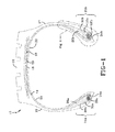
- FIG. 1 shows an example tire 10 for use with reinforcing structures, such as flippers, in accordance with the present invention.
- the example tire 10 has a tread 12, an inner liner 23, a belt structure 16 comprising belts 18, 20, a carcass 22 with preferably a single carcass ply 14, two sidewalls 15,17, and two bead regions 24a, 24b comprising bead filler apexes 26a, 26b and beads 28a, 28b.
- the example tire 10 is suitable, for example, for mounting on a rim of a passenger vehicle.
- the carcass ply 14 includes a pair of axially opposite end portions 30a, 30b, each of which is secured to a respective one of the beads 28a, 28b.
- Each axial end portion 30a or 30b of the carcass ply 14 is turned up and around the respective bead 28a, 28b to a position sufficient to anchor each axial end portion 30a, 30b, as seen in detail in FIGS. 1 and 2 .
- the carcass ply 14 may be a rubberized ply having a plurality of substantially parallel carcass reinforcing members made of such material as polyester, rayon, or similar suitable organic polymeric compounds.
- the carcass ply 14 engages the axial outer surfaces of two flippers 32a, 32b and the axial inner surfaces of two chippers 34a, 34b.
- FIG. 3 shows, in cross-sectional view, the bead region of another example tire for use with reinforcing structures, such as flippers, in accordance with the present invention.
- a carcass ply 50 wraps around a bead 52b and is separated from the bead by a flipper 54.
- the flipper 54 may be a layer of knitted fabric disposed around the bead 52b and inward of a portion of the carcass ply 50 which turns up under the bead.
- the knitted fabric flipper 54 may have and preferably has physical properties (such as shearing modulus of elasticity) intermediate to those of a rigid metal bead 52b and a less rigid carcass ply 50.
- the knitted fabric flipper 54 therefore may serve as an active strain-relieving layer separating the bead 52b from the carcass ply 50.
- the carcass ply 50 may be reinforced with metal, as is conventional in the tire art.
- the example tire of FIG. 3 also may have a fabric chipper 56 located in the bead area for reinforcing the bead area and stabilizing the axially inwardmost part of the sidewall 57.
- the flipper 54 and chipper 56, along with the patch 58 uniting them, are discussed separately below, and then in operational conjunction with one another.
- the knitted fabric flipper 54 wraps around the bead 52b and extends radially outward into the sidewall regions of the example tire.
- the axially inward portion 55 of knitted fabric flipper 54 terminates within the bead-filler apex 59b.
- the axially outward portion 60b of the knitted fabric flipper 54 lies radially beyond a turnup end 62b, which itself is located radially beyond the radially outermost reach of the chipper 56 (discussed separately below).
- the axially outwardmost portions of the turnup end 62b of the carcass ply 50 may extend radially outward 15-30 millimeters beyond the top of a wheel rim flange 72 of a wheel rim 70.
- the knitted fabric flipper 54 is deployed about the bead 52b which is itself circumferentially disposed within the example tire.
- An axially inward portion 55 of the knitted fabric flipper 54 extends radially outward from the bead 52b to a location approximately axially adjacent to the top of the wheel rim flange 72 of the wheel rim 70.
- the knitted fabric flipper 54 extends radially outward from the bead 52b to an end 60b above the wheel rim flange 72.
- the radially outermost reach of the end 60b of the knitted fabric flipper 54 may extend between 7-15 millimeters beyond the radially outermost reach of the turnup end 62b.
- the knitted fabric flipper 54 may be termed "active" because it actively absorbs (i.e. during tire deflection) differential strains between the relatively rigid bead 52b and the relatively less rigid carcass ply 50.
- the chipper 56 is disposed adjacent to the portion of the carcass ply 50 that is wrapped around the bead 52b. More specifically, the chipper 56 is disposed on the opposite side of the portion of the carcass ply 50 from the knitted fabric flipper 54. The axially inwardmost portion of the knitted fabric chipper 56 lies in the portion of the bead region that, when the tire is mounted on the wheel rim 70, would lie closest to a circularly cylindrical part 74 of the wheel rim.
- the axially and radially outwardmost portion of the chipper 56 lies in the portion of the bead region that, when the tire is mounted on the wheel rim 70, would lie axially inward of the circular portion of the wheel rim 70, being separated from the circular portion of the wheel rim by tire rubber such as a toe guard 64.
- the chipper 56 is disposed circumferentially about the radially inwardmost portion of the carcass ply 50 where the carcass ply turns up under the bead 52b.
- the chipper 56 may extend radially outward, being more or less parallel with the turned up end 62b of the carcass ply 50.
- the chipper 56 may protect the portion of the carcass ply 50 that wraps around the bead 52b from the strains in the rubber that separates the chipper from the wheel rim 70.
- the chipper 56 reinforces the bead area and stabilizes the radially inwardmost part of the sidewall 57. In other words, the chipper 56 may absorb deformation in a way that minimizes the transmission of stress-induced shearing strains that arise inward from the wheel rim 70, through the toe guard 64, to the turned up portion 62b of the carcass ply 50, where the chipper is most immediately adjacent to the rigid bead 52b.
- the optional patch 58 shown in FIG. 3 is circumferentially disposed about the bead 52b in such a way as to overlie the radially outermost regions 68 of the chipper 56 and the turned up ends 62b of the carcass ply 50.
- the patch 58 performs a function similar to that of those of the chipper 56 and the knitted fabric flipper 54. More specifically, the patch 58 may absorb shearing stresses in the rubber parts which might otherwise induce separation of the flexible rubber from the less flexible material of the chipper 56 and the carcass ply 50.
- the patch 58 may, for example, be made of nylon fabric.
- the radially outwardmost portion 67 of the patch 58 may reach to a minimum level such as extending by at least 5 mm above the upper end 60b of the knitted fabric flipper 54, and preferably 10-15 mm above.
- the radially inwardmost portion of the patch 58 may overlap 10 mm with the chipper 56.
- the net effect of the incorporation of the knitted fabric flipper 54 is to provide a strain buffer that relieves or absorbs differential shearing strains that otherwise, were the flippers not present, could lead to separation of the adjacent materials that have disparate shearing moduli of elasticity. Furthermore, this reinforced construction may increase durability of the tire by means of the incorporation of a smaller number of components than for standard constructions with gum strips.
- the knitted fabric flippers 32a, 32b, 54 of the example tires of FIGS. 1-3 may comprise knitted fabric.
- a flipper 54 may comprise a layer 300 of knitted fabric having a first set of yarns 310 interlaced with a second set of yarns 320.
- the layer 300 of the knitted fabric flippers 32a, 32b, 54 may be made of a highly deformable elastic knitted fabric of low apparent density, allowing elasticity due to sliding of the threads and the deformation of the stitches.
- the construction of the layer 300 may further allow some degree of mechanical decoupling between the different yarns 310, 320 thereby providing structural flexibility in adapting to the deformations of the tire 10 during use.
- Various kinds of material may be selected to produce this layer 300. Thickness, proportion of voids, and density may be directly related to the material and the structure of the knitted fabric layer 300 (thread diameter, number of stitches per dm, tightness).
- the layer 300 may thus define a bielastic fabric having an elastic elongation ratio of at least 8% and a stitch size of less than or equal to 150 stitches per decimeter.
- the layer may be constructed of synthetic fibers, natural fibers, and/or a blend of these fibers.
- the layer 300 may comprise polyamides, polyesters, rayon, cotton, wool, aramid, silk and/or flax.
- the bielastic/knitted fabric flipper 32a, 32b, 54 in accordance with the present invention may have a thickness from 0.2 mm to 2 mm and a mass per unit area from 70 to 700 g/m 2 . Further, the bielastic/knitted fabric flipper 32a, 32b, 54 may have a density from 0.02 g/cm 3 to 0.50 g/cm 3 .
- the bielastic/knitted fabric flipper 32a, 32b, 54 may have a void volume of at least 40% so that the knitted fabric will be sufficiently compressible.
- the void volume may be calculated by comparing the density of the knitted fabric with that of the compact material forming its matrix, measured by any suitable.
- Non-elastomeric materials may also be used for the matrix of the bielastic/knitted fabric flipper 32a, 32b, 54, including natural textile fibers such as cotton, wool, flax, hemp, silk, etc., artificial textile fibers such as rayon, synthetic textile fibers such as polyester, polyvinyl acetate, nylon (including nylon 6, nylon 6,6, and nylon 4,6), polyethylene naphthalate (PEN), rayon, polyketone, PBO polyamide, aramid, polyvinyl chloride, polyolefins, etc., and/or mineral fibers such as glass, carbon, silica, mineral wool, etc.
- the elastomeric material may be natural rubber, polybutadiene, SBR, polyurethane, etc.
- the yarns 310, 320 may be a spun staple yarn, a multifilament yarn, and/or a monofilament yarn formed of a suitable material.
- the yarns 310, 320 may also be hybrid yarns.
- Hybrid yarns may be multiply yarns, made up of at least 2 fibers of different material (for example, cotton and nylon). These different fiber materials may produce hybrid yarns with various chemical and physical properties.
- Hybrid yarns may be able to change the physical properties of the final product in which they are used.
- Example hybrid yarns may be an aramid fiber with a nylon fiber, an aramid fiber with a rayon fiber, and an aramid fiber with a polyester fiber.
- mechanical resiliency of a yarn is the ability of the yarn to displace longitudinally without an elastic deformation of the material. Mechanical resiliency allows the knitted fabric layer 300 to have a minor amount of resilient elongation for compatibility with the example tires of FIGS. 1-3 , but use stronger yarns in the flipper 32a, 32b, 54.
- the knitted fabric layer 300 is an open construction fabric which permits the strike through of rubber in a tire for a better bonded construction.
- the openness of the fabric used for the layer 300 is usually determined by the spacing and character of the yarns 310, 320.
- the layer 300 may be treated with an adhesion promoter.
- adhesion promoters include resorcinol formaldehyde latex (RFL), isocyanate based material, epoxy based material, and materials based on melamine formaldehyde resin.
- the LENO tape may also have a tackified finish, or green tack, applied for facilitating adhesion during the building process of a green tire.
- the selection of materials for the tackified finish may depend upon the materials selected for use in the tire. Tackified finishes may be achieved by various methods such as coating the fabric in an aqueous blend of rosin and rubber lattices, or with a solvent solution of an un-vulcanized rubber compound.
- the flipper 32a, 32b, 54 may comprise multiple layers 300, e.g. two, three, or even more layers, to provide extra strength for the flipper.
- a layer of unvulcanized rubber may be placed between the layers to ensure an effective bond.
- the formation of the layer 300 may begin with the acquisition of the basic yarns for the fabric. Subsequently, the yarns may be twisted to provide additional mechanical resilience. After the twisting, the yarns 310, 320 may be placed on a large beam for the formation of the layer 300.
- the layer 300 may be formed knitting with the appropriate spacing of the yarns 310, 320.
- the layer may be finished with adhesive promoter, such as an RFL treatment. If a tackified finish is desired, this is provided following the adhesive promoter finishing.
- the final layer may be slit into the specific widths for placement on a spool.
- the flipper 32a, 32b, 54 in accordance with the present invention improves prior art runflat and high performance tires by optimizing runflat mileage, high speed capability, and handling characteristics, without increasing manufacturing complexity. Additionally, the flipper 32a, 32b, 54 may reduce noise due to vibration damping in the bead area (i.e., circumferential reinforcement provided knitted layer 300). Further, the layer 300 need not be calendered and may be applied at the tire building machine (i.e., a spool of the layer 300 directly applied at the tire building machine). Also, the layer 300 may be applied symmetrically to both beads, or asymmetrically to only one bead. The width of the layer 300 may depend on specific design requirements.
- the yarns 310, 320 of the flipper 32b, 54 may be oriented radially or at an angle, such as in a range from 15 to 60 degrees, or more specifically from 30 to 55 degrees, with respect to the circumferential direction of the tire.
- the yarns 310, 320 may have a density of 5 EPI to 18 EPI.
- a flipper 32a, 32b, 54 in accordance with the present invention produces increased runflat mileage, high speed capability and handling characteristics, and vibration damping, without increasing manufacturing complexity.
- This flipper 32a, 32b, 54 thus enhances the performance of the pneumatic tire 10, even though the complexities of the structure and behavior of the pneumatic tire are such that no complete and satisfactory theory has been propounded.
- Flipper and chipper cord characteristics affect the other components of a pneumatic tire (i.e., flipper/chipper affects carcass ply, belt, overlay, etc.), leading to a number of components interrelating and interacting in such a way as to affect a group of functional properties (noise, handling, durability, comfort, high speed, and mass), resulting in an unpredictable and complex composite. Whether one or more functional characteristics of the tire is improved, degraded, or unaffected, and by what amount, is unpredictable without the insight, experimentation, and testing conducted by the inventors.
Landscapes
- Engineering & Computer Science (AREA)
- Mechanical Engineering (AREA)
- Textile Engineering (AREA)
- Tires In General (AREA)
Abstract
Description
- The present invention relates to a pneumatic tire, and more particularly, to a radial pneumatic tire with a flipper.
- A pneumatic tire typically includes a pair of axially separated inextensible beads. A circumferentially disposed bead filler apex extends radially outward from each respective bead. At least one carcass ply extends between the two beads. The carcass ply has axially opposite end portions, each of which is turned up around a respective bead and secured thereto. Tread rubber and sidewall rubber is located axially and radially outward, respectively, of the carcass ply.
- The bead area is one part of the tire that contributes a substantial amount to the rolling resistance of the tire, due to cyclical flexure which also leads to heat buildup. Under conditions of severe operation, as with runflat and high performance tires, the flexure and heating in the bead region can be especially problematic, leading to separation of mutually adjacent components that have disparate properties, such as the respective moduli of elasticity. In particular, the ply turnup ends may be prone to separation from adjacent structural elements of the tire.
- A conventional ply may be reinforced with materials such as nylon, polyester, rayon, and/or metal, which have much greater stiffness (i.e., modulus of elasticity) than the adjacent rubber compounds of which the bulk of the tire is made. The difference in elastic modulus of mutually adjacent tire elements may lead to separation when the tire is stressed and deformed during use.
- A variety of structural design approaches have been used to control separation of tire elements in the bead regions of a tire. For example, one method has been to provide a "flipper" surrounding the bead and the bead filler. The flipper works as a spacer that keeps the ply from making direct contact with the inextensible beads, allowing some degree of relative motion between the ply, where it turns upward under the bead, and the respective beads. In this role as a spacer, a flipper may reduce disparities of strain on the ply and on the adjacent rubber components of the tire (e.g., the filler apex, the sidewall rubber, in the bead region, and the elastomeric portions of the ply itself).
- The flipper may be made of a fabric in which each fiber, thread, or cord has a generally round cross-section. When a flipper is cured with a tire, the stiffness of the fibers/cords becomes essentially the same in any direction within the plane of the flipper.
- In addition to the use of flippers as a means by which to reduce the tendency of a ply to separate, or as an alternative, another method that has been used involves the placement of "chippers." A chipper is a circumferentially deployed metal or fabric layer that is disposed within the bead region in the portion of the tire where the bead fits onto the wheel rim. More specifically, the chipper lies inward of the wheel rim (i.e., toward the bead) and outward (i.e., radially outward, relative to the bead viewed in cross section) of the portion of the ply that turns upward around the bead. Chippers serve to stiffen, and increase the resistance to flexure of, the adjacent rubber material, which itself is typically adjacent to the turnup ply endings.
- The invention relates to a pneumatic tire in accordance with claim 1. Dependent claims refer to preferred embodiments of the invention.
- In one aspect, a pneumatic tire in accordance with the present invention includes an axis of rotation, a carcass, a tread disposed radially outward of the carcass, a belt structure disposed radially between the carcass and the tread, and a reinforcing structure providing a buffer for absorbing shear strain. The reinforcing structure includes a layer of a knitted fabric. The layer includes first yarns and second yarns.
- In one preferred aspect of the present invention, the reinforcing structure of the carcass is a flipper.
- In another preferred aspect of the present invention, the flipper separates a reinforced ply of the carcass from a bead of the carcass.
- In still another preferred aspect of the present invention, the flipper acts as a strain-relieving layer between the bead and the reinforced ply.
- In yet another preferred aspect of the present invention, the fabric has a 5 EPI to 18 EPI construction.
- In still another preferred aspect of the present invention, the first yarns are 940/1 dtex aramid and the second yarns are 1220/1 dtex rayon.
- In yet another preferred aspect of the present invention, the first yarns have a density of 14 EPI and the second yarns have a density of 12 EPI.
- In still another preferred aspect of the present invention, the pneumatic tire is a radial runflat passenger tire.
- In yet another preferred aspect of the present invention, the pneumatic tire is a high performance tire.
- In still another preferred aspect of the present invention, the layer further comprises an adhesion promoter disposed thereon.
- In yet another preferred aspect of the present invention, the reinforcing structure of the carcass is a flipper having two or more layers.
- In still another preferred aspect of the present invention, the flipper includes a layer of rubber between the fabric layers.
- In yet another preferred aspect of the present invention, the first yarns comprise at least two fibers of different fiber materials.
- In still another preferred aspect of the present invention, the second yarns comprise at least two fibers of different fiber materials.
- In yet another preferred aspect of the present invention, the first yarns extend circumferentially and radially at an angle of 30 degrees to 55 degrees relative to the radial direction of the tire.
- In still another preferred aspect of the present invention, the reinforcing structure separates a reinforced ply of the carcass from a bead of the carcass, the reinforcing structure terminating within an apex of the pneumatic tire.
- In still another aspect of the invention, the reinforcing structure is a chipper or a patch uniting flipper and dripper in the bead area of the tire.
- "Apex" means an elastomeric filler located radially above the bead core and between the plies and the turnup ply.
- "Axial" and "axially" are used herein to refer to lines or directions that are parallel to the axis of rotation of the tire.
- "Cable" means a cord formed by twisting together two or more plied yarns.
- "Carcass" means the tire structure apart from the belt structure, tread, undertread, and sidewall rubber over the plies, but including the beads.
- "Chipper" refers to a preferably narrow band of fabric or cords such as steel cords located in the bead area whose function is to reinforce the bead area and stabilize the radially inwardmost part of the sidewall.
- "Circumferential" means lines or directions extending along the perimeter of the surface of the annular tire parallel to the Equatorial Plane (EP) and perpendicular to the axial direction.
- "Cord" means one of the reinforcement strands which the reinforcement structures of the tire comprise.
- "Flipper" refers to a reinforcing fabric around the bead wire for strength and to tie the bead wire in the tire body.
- "Ply" means a cord-reinforced layer of rubber-coated radially deployed or otherwise parallel cords.
- "Radial" and "radially" are used to mean directions radially toward or away from the axis of rotation of the tire.
- "Yarn" is a generic term for a continuous strand of textile fibers or filaments. Yarn occurs in the following forms: 1) a number of fibers twisted together; 2) a number of filaments laid together without twist; 3) a number of filaments laid together with a degree of twist; 4) a single filament with or without twist (monofilament); 5) a narrow strip of material with or without twist.
- The structure, operation, and advantages of the invention will become more apparent upon contemplation of the following description taken in conjunction with the accompanying drawings, wherein:
-
FIG. 1 represents a schematic cross-sectional view of an example tire for use with the present invention; -
FIG. 2 represents a schematic detail view of the bead region of the example tire shown inFIG. 1 ; -
FIG. 3 represents a schematic detail view of another bead region for use with present invention; and -
FIG. 4 represents a schematic detail of an example fabric in accordance with the present invention. -
FIG. 1 shows anexample tire 10 for use with reinforcing structures, such as flippers, in accordance with the present invention. Theexample tire 10 has atread 12, aninner liner 23, a belt structure 16 comprisingbelts 18, 20, acarcass 22 with preferably asingle carcass ply 14, twosidewalls bead regions bead filler apexes beads example tire 10 is suitable, for example, for mounting on a rim of a passenger vehicle. The carcass ply 14 includes a pair of axiallyopposite end portions beads axial end portion respective bead axial end portion FIGS. 1 and2 . - The carcass ply 14 may be a rubberized ply having a plurality of substantially parallel carcass reinforcing members made of such material as polyester, rayon, or similar suitable organic polymeric compounds. The carcass ply 14 engages the axial outer surfaces of two
flippers chippers -
FIG. 3 shows, in cross-sectional view, the bead region of another example tire for use with reinforcing structures, such as flippers, in accordance with the present invention. A carcass ply 50 wraps around abead 52b and is separated from the bead by aflipper 54. Theflipper 54 may be a layer of knitted fabric disposed around thebead 52b and inward of a portion of the carcass ply 50 which turns up under the bead. The knittedfabric flipper 54 may have and preferably has physical properties (such as shearing modulus of elasticity) intermediate to those of arigid metal bead 52b and a lessrigid carcass ply 50. The knittedfabric flipper 54 therefore may serve as an active strain-relieving layer separating thebead 52b from thecarcass ply 50. The carcass ply 50 may be reinforced with metal, as is conventional in the tire art. - The example tire of
FIG. 3 also may have afabric chipper 56 located in the bead area for reinforcing the bead area and stabilizing the axially inwardmost part of thesidewall 57. Theflipper 54 andchipper 56, along with thepatch 58 uniting them, are discussed separately below, and then in operational conjunction with one another. - The knitted
fabric flipper 54 wraps around thebead 52b and extends radially outward into the sidewall regions of the example tire. The axiallyinward portion 55 of knittedfabric flipper 54 terminates within the bead-filler apex 59b. The axiallyoutward portion 60b of the knittedfabric flipper 54 lies radially beyond aturnup end 62b, which itself is located radially beyond the radially outermost reach of the chipper 56 (discussed separately below). The axially outwardmost portions of theturnup end 62b of the carcass ply 50 may extend radially outward 15-30 millimeters beyond the top of awheel rim flange 72 of awheel rim 70. - As shown in
FIG. 3 , the knittedfabric flipper 54 is deployed about thebead 52b which is itself circumferentially disposed within the example tire. An axiallyinward portion 55 of the knittedfabric flipper 54 extends radially outward from thebead 52b to a location approximately axially adjacent to the top of thewheel rim flange 72 of thewheel rim 70. On an axially outward side, the knittedfabric flipper 54 extends radially outward from thebead 52b to anend 60b above thewheel rim flange 72. The radially outermost reach of theend 60b of the knittedfabric flipper 54 may extend between 7-15 millimeters beyond the radially outermost reach of theturnup end 62b. The knittedfabric flipper 54 may be termed "active" because it actively absorbs (i.e. during tire deflection) differential strains between the relativelyrigid bead 52b and the relatively lessrigid carcass ply 50. - The
chipper 56 is disposed adjacent to the portion of the carcass ply 50 that is wrapped around thebead 52b. More specifically, thechipper 56 is disposed on the opposite side of the portion of the carcass ply 50 from the knittedfabric flipper 54. The axially inwardmost portion of the knittedfabric chipper 56 lies in the portion of the bead region that, when the tire is mounted on thewheel rim 70, would lie closest to a circularlycylindrical part 74 of the wheel rim. The axially and radially outwardmost portion of thechipper 56 lies in the portion of the bead region that, when the tire is mounted on thewheel rim 70, would lie axially inward of the circular portion of thewheel rim 70, being separated from the circular portion of the wheel rim by tire rubber such as atoe guard 64. - In other words, as can be seen in
FIG. 3 , thechipper 56 is disposed circumferentially about the radially inwardmost portion of the carcass ply 50 where the carcass ply turns up under thebead 52b. Thechipper 56 may extend radially outward, being more or less parallel with the turned upend 62b of thecarcass ply 50. - The
chipper 56 may protect the portion of the carcass ply 50 that wraps around thebead 52b from the strains in the rubber that separates the chipper from thewheel rim 70. Thechipper 56 reinforces the bead area and stabilizes the radially inwardmost part of thesidewall 57. In other words, thechipper 56 may absorb deformation in a way that minimizes the transmission of stress-induced shearing strains that arise inward from thewheel rim 70, through thetoe guard 64, to the turned upportion 62b of thecarcass ply 50, where the chipper is most immediately adjacent to therigid bead 52b. - The
optional patch 58 shown inFIG. 3 is circumferentially disposed about thebead 52b in such a way as to overlie the radiallyoutermost regions 68 of thechipper 56 and the turned up ends 62b of thecarcass ply 50. Thepatch 58 performs a function similar to that of those of thechipper 56 and theknitted fabric flipper 54. More specifically, thepatch 58 may absorb shearing stresses in the rubber parts which might otherwise induce separation of the flexible rubber from the less flexible material of thechipper 56 and thecarcass ply 50. Thepatch 58 may, for example, be made of nylon fabric. Theradially outwardmost portion 67 of thepatch 58 may reach to a minimum level such as extending by at least 5 mm above theupper end 60b of the knittedfabric flipper 54, and preferably 10-15 mm above. The radially inwardmost portion of thepatch 58 may overlap 10 mm with thechipper 56. - The net effect of the incorporation of the knitted
fabric flipper 54 is to provide a strain buffer that relieves or absorbs differential shearing strains that otherwise, were the flippers not present, could lead to separation of the adjacent materials that have disparate shearing moduli of elasticity. Furthermore, this reinforced construction may increase durability of the tire by means of the incorporation of a smaller number of components than for standard constructions with gum strips. - In accordance with the present invention, the knitted
fabric flippers FIGS. 1-3 may comprise knitted fabric. As illustrated in the example ofFIG. 4 , aflipper 54 may comprise alayer 300 of knitted fabric having a first set ofyarns 310 interlaced with a second set ofyarns 320. - The
layer 300 of the knittedfabric flippers layer 300 may further allow some degree of mechanical decoupling between thedifferent yarns tire 10 during use. Various kinds of material may be selected to produce thislayer 300. Thickness, proportion of voids, and density may be directly related to the material and the structure of the knitted fabric layer 300 (thread diameter, number of stitches per dm, tightness). - The
layer 300 may thus define a bielastic fabric having an elastic elongation ratio of at least 8% and a stitch size of less than or equal to 150 stitches per decimeter. The layer may be constructed of synthetic fibers, natural fibers, and/or a blend of these fibers. Thelayer 300 may comprise polyamides, polyesters, rayon, cotton, wool, aramid, silk and/or flax. - A proportion of elastic threads such as polyurethane, latex, natural, or synthetic rubber may be useful to provide the elastic return, which aids in application of the fabric. Thus, as an example, the bielastic/knitted
fabric flipper fabric flipper - Additionally, the bielastic/knitted
fabric flipper - Non-elastomeric materials may also be used for the matrix of the bielastic/knitted
fabric flipper - The
yarns yarns - As used herein, mechanical resiliency of a yarn is the ability of the yarn to displace longitudinally without an elastic deformation of the material. Mechanical resiliency allows the knitted
fabric layer 300 to have a minor amount of resilient elongation for compatibility with the example tires ofFIGS. 1-3 , but use stronger yarns in theflipper - The
knitted fabric layer 300 is an open construction fabric which permits the strike through of rubber in a tire for a better bonded construction. The openness of the fabric used for thelayer 300 is usually determined by the spacing and character of theyarns - The
layer 300 may be treated with an adhesion promoter. Examples of adhesion promoters include resorcinol formaldehyde latex (RFL), isocyanate based material, epoxy based material, and materials based on melamine formaldehyde resin. The LENO tape may also have a tackified finish, or green tack, applied for facilitating adhesion during the building process of a green tire. The selection of materials for the tackified finish may depend upon the materials selected for use in the tire. Tackified finishes may be achieved by various methods such as coating the fabric in an aqueous blend of rosin and rubber lattices, or with a solvent solution of an un-vulcanized rubber compound. - Further, the
flipper multiple layers 300, e.g. two, three, or even more layers, to provide extra strength for the flipper. When more than onelayer 300 is used for theflipper layer 300 may begin with the acquisition of the basic yarns for the fabric. Subsequently, the yarns may be twisted to provide additional mechanical resilience. After the twisting, theyarns layer 300. Thelayer 300 may be formed knitting with the appropriate spacing of theyarns layer 300 formation, the layer may be finished with adhesive promoter, such as an RFL treatment. If a tackified finish is desired, this is provided following the adhesive promoter finishing. The final layer may be slit into the specific widths for placement on a spool. - The
flipper flipper layer 300 need not be calendered and may be applied at the tire building machine (i.e., a spool of thelayer 300 directly applied at the tire building machine). Also, thelayer 300 may be applied symmetrically to both beads, or asymmetrically to only one bead. The width of thelayer 300 may depend on specific design requirements. Theyarns flipper yarns - As stated above, a
flipper flipper pneumatic tire 10, even though the complexities of the structure and behavior of the pneumatic tire are such that no complete and satisfactory theory has been propounded. - Flipper and chipper cord characteristics affect the other components of a pneumatic tire (i.e., flipper/chipper affects carcass ply, belt, overlay, etc.), leading to a number of components interrelating and interacting in such a way as to affect a group of functional properties (noise, handling, durability, comfort, high speed, and mass), resulting in an unpredictable and complex composite. Whether one or more functional characteristics of the tire is improved, degraded, or unaffected, and by what amount, is unpredictable without the insight, experimentation, and testing conducted by the inventors.
Claims (15)
- A pneumatic tire comprising a reinforcing structure (32a, 32b, 54) comprising a layer of knitted fabric (300) comprising first yarns (310) and second yarns (320).
- The pneumatic tire of claim 1 wherein the reinforcing structure (32a, 32b, 54) provides a buffer for absorbing shear strain.
- The pneumatic tire of claim 1 or 2 comprising a carcass (22), a tread (12) disposed radially outward of the carcass (22) and a belt structure (16) disposed radially between the carcass (22) and the tread (12).
- The pneumatic tire of at least one of the previous claims wherein the reinforcing structure (32a, 32b, 54) is a flipper.
- The pneumatic tire of claim 4 wherein the flipper separates a reinforced ply (14) of the carcass from a bead (28a, 28b) of the carcass.
- The pneumatic tire of claim 4 or 5 wherein the flipper is a strain-relieving layer between the bead and the reinforced ply.
- The pneumatic tire of at least one of the previous claims wherein the reinforcing structure (32a, 32b, 54) has a 5 ends per 2.54 cm (epi) to 18 ends per 2.54 cm construction.
- The pneumatic tire of at least one of the previous claims wherein the material of the first yarns (310) is different from the material of the second yarns (320), and/or wherein at least one of the density, the yarn construction and the dtex of the first yarns (310) is different from the respective parameter of the second yarns (320).
- The pneumatic tire of at least one of the previous claims wherein the material of the first yarns (310) is polyaramide and the material of the second yarns (320) is rayon; and/or wherein the first yarns (310) are a 940/1 dtex polyaramide yarns and the second yarns (320) are a 1220/1 dtex rayon yarns.
- The pneumatic tire of at least one of the previous claims wherein the first yarns (310) have a density of 14 ends per 2.54 cm (epi) and the second yarns (320) have a density of 12 ends per 2.54 cm construction; and/or wherein the first yarns (310) have a density of at least 2 ends per 2.54 cm higher than the second yarns (320).
- The pneumatic tire of at least one of the previous claims wherein the layer of knitted fabric (300) comprises an adhesion promoter disposed thereon.
- The pneumatic tire of at least one of the previous claims wherein the flipper comprises two or more layers, or wherein the flipper comprises two or more fabric layers and a layer of rubber between the fabric layers.
- The pneumatic tire of at least one of the previous claims wherein the first yarns (310) and/or the second yarns (320) comprise at least two fibers of different materials.
- The pneumatic tire of at least one of the previous claims wherein the first yarns (310) extend at an angle of 30 to 55 degrees relative to the radial direction of the tire (10); and/or wherein the reinforcing structure (32a, 32b, 54) separates a reinforced ply (14) of the carcass from a bead (28a, 28b) of the carcass, the reinforcing structure (32a, 32b, 54) terminating within an apex (26a, 26b) of the pneumatic tire (10).
- The pneumatic tire of at least one of the previous claims wherein the tire (10) is a runflat passenger tire.
Applications Claiming Priority (1)
| Application Number | Priority Date | Filing Date | Title |
|---|---|---|---|
| US12/899,803 US20120085475A1 (en) | 2010-10-07 | 2010-10-07 | Pneumatic tire with a knitted flipper |
Publications (2)
| Publication Number | Publication Date |
|---|---|
| EP2439084A1 true EP2439084A1 (en) | 2012-04-11 |
| EP2439084B1 EP2439084B1 (en) | 2014-09-03 |
Family
ID=44759519
Family Applications (1)
| Application Number | Title | Priority Date | Filing Date |
|---|---|---|---|
| EP11183926.2A Not-in-force EP2439084B1 (en) | 2010-10-07 | 2011-10-05 | A pneumatic tire with a knitted fabric as reinforcing structure |
Country Status (5)
| Country | Link |
|---|---|
| US (1) | US20120085475A1 (en) |
| EP (1) | EP2439084B1 (en) |
| KR (1) | KR20120036290A (en) |
| CN (1) | CN102442159A (en) |
| BR (1) | BRPI1107081A2 (en) |
Cited By (2)
| Publication number | Priority date | Publication date | Assignee | Title |
|---|---|---|---|---|
| EP2835276A1 (en) * | 2013-08-07 | 2015-02-11 | The Goodyear Tire & Rubber Company | A pneumatic tire with a reinforced flipper or chipper |
| US11186122B2 (en) | 2015-08-31 | 2021-11-30 | The Goodyear Tire & Rubber Company | Reduced weight aircraft tire |
Families Citing this family (6)
| Publication number | Priority date | Publication date | Assignee | Title |
|---|---|---|---|---|
| FR2996807B1 (en) * | 2012-10-12 | 2015-01-02 | Michelin & Cie | PNEUMATIC ADAPTABLE FOR FLAT ROLLING INCLUDING HYBRID CARCASS TABLET. |
| CN103738120B (en) * | 2014-01-07 | 2016-06-01 | 中策橡胶集团有限公司 | The all-steel radial tyre of a kind of double-layer wire reinforced bead and its preparation method |
| US11827064B2 (en) * | 2015-08-31 | 2023-11-28 | The Goodyear Tire & Rubber Company | Reduced weight aircraft tire |
| JP2019085052A (en) * | 2017-11-09 | 2019-06-06 | Toyo Tire株式会社 | Pneumatic tire for heavy load |
| CN109835124B (en) * | 2019-02-28 | 2021-01-01 | 安徽佳通乘用子午线轮胎有限公司 | Tire capable of reducing rolling resistance and keeping seam allowance durable |
| US20210300120A1 (en) * | 2020-03-30 | 2021-09-30 | The Goodyear Tire & Rubber Company | Shear band |
Citations (7)
| Publication number | Priority date | Publication date | Assignee | Title |
|---|---|---|---|---|
| US3240251A (en) * | 1963-04-05 | 1966-03-15 | Burlington Industries Inc | Cotton tire fabric and method of making same |
| US3679516A (en) * | 1969-04-03 | 1972-07-25 | Burlington Industries Inc | Process for producing an air-impervious tire fabric |
| EP0573853A1 (en) * | 1992-06-12 | 1993-12-15 | Michelin Recherche Et Technique S.A. | Tire flipper structure |
| US6659148B1 (en) * | 1998-12-01 | 2003-12-09 | The Goodyear Tire & Rubber Company | Bead reinforcing structure for radial truck tires |
| EP2147805A2 (en) * | 2008-07-22 | 2010-01-27 | The Goodyear Tire & Rubber Company | Pneumatic tire |
| US20100065179A1 (en) * | 2008-09-15 | 2010-03-18 | Serge Julien Auguste Imhoff | pneumatic tire with a leno weave flipper or chipper |
| EP2165861A1 (en) * | 2008-09-18 | 2010-03-24 | The Goodyear Tire & Rubber Company | Turnup reinforcing structure for pneumatic tires |
Family Cites Families (2)
| Publication number | Priority date | Publication date | Assignee | Title |
|---|---|---|---|---|
| DE1065287B (en) * | 1957-06-21 | |||
| JP4953550B2 (en) * | 2003-08-22 | 2012-06-13 | 株式会社ブリヂストン | Pneumatic tire |
-
2010
- 2010-10-07 US US12/899,803 patent/US20120085475A1/en not_active Abandoned
-
2011
- 2011-09-30 CN CN2011102930035A patent/CN102442159A/en active Pending
- 2011-10-03 BR BRPI1107081A patent/BRPI1107081A2/en not_active IP Right Cessation
- 2011-10-05 EP EP11183926.2A patent/EP2439084B1/en not_active Not-in-force
- 2011-10-07 KR KR1020110102350A patent/KR20120036290A/en not_active Ceased
Patent Citations (7)
| Publication number | Priority date | Publication date | Assignee | Title |
|---|---|---|---|---|
| US3240251A (en) * | 1963-04-05 | 1966-03-15 | Burlington Industries Inc | Cotton tire fabric and method of making same |
| US3679516A (en) * | 1969-04-03 | 1972-07-25 | Burlington Industries Inc | Process for producing an air-impervious tire fabric |
| EP0573853A1 (en) * | 1992-06-12 | 1993-12-15 | Michelin Recherche Et Technique S.A. | Tire flipper structure |
| US6659148B1 (en) * | 1998-12-01 | 2003-12-09 | The Goodyear Tire & Rubber Company | Bead reinforcing structure for radial truck tires |
| EP2147805A2 (en) * | 2008-07-22 | 2010-01-27 | The Goodyear Tire & Rubber Company | Pneumatic tire |
| US20100065179A1 (en) * | 2008-09-15 | 2010-03-18 | Serge Julien Auguste Imhoff | pneumatic tire with a leno weave flipper or chipper |
| EP2165861A1 (en) * | 2008-09-18 | 2010-03-24 | The Goodyear Tire & Rubber Company | Turnup reinforcing structure for pneumatic tires |
Cited By (2)
| Publication number | Priority date | Publication date | Assignee | Title |
|---|---|---|---|---|
| EP2835276A1 (en) * | 2013-08-07 | 2015-02-11 | The Goodyear Tire & Rubber Company | A pneumatic tire with a reinforced flipper or chipper |
| US11186122B2 (en) | 2015-08-31 | 2021-11-30 | The Goodyear Tire & Rubber Company | Reduced weight aircraft tire |
Also Published As
| Publication number | Publication date |
|---|---|
| EP2439084B1 (en) | 2014-09-03 |
| CN102442159A (en) | 2012-05-09 |
| BRPI1107081A2 (en) | 2015-12-29 |
| US20120085475A1 (en) | 2012-04-12 |
| KR20120036290A (en) | 2012-04-17 |
Similar Documents
| Publication | Publication Date | Title |
|---|---|---|
| US7992611B2 (en) | Pneumatic tire with a leno weave flipper or chipper | |
| EP2439080B1 (en) | A pneumatic tire with a woven or knitted reinforcement | |
| EP2439084B1 (en) | A pneumatic tire with a knitted fabric as reinforcing structure | |
| US7874335B2 (en) | Tire with cap ply layer | |
| EP2810791B1 (en) | Pneumatic tire and hybrid cord for such a pneumatic tire | |
| WO2009052844A1 (en) | Tire having a structural element reinforced with a hybrid yarn | |
| EP2604448B1 (en) | Composite cord and overlay ply for a pneumatic tire | |
| US4735249A (en) | Pneumatic radial passenger-car tire | |
| US20110240199A1 (en) | Pneumatic tire for vehicles | |
| EP2439081B1 (en) | A pneumatic tire with a woven or knitted reinforcement | |
| US20120168059A1 (en) | Pneumatic tire and method for making a pneumatic tire | |
| EP2835276A1 (en) | A pneumatic tire with a reinforced flipper or chipper | |
| CN105517814A (en) | Method for increasing the performances of a tyre for vehicle wheels and tyre for vehicle wheels | |
| US20120085474A1 (en) | Pneumatic tire with a woven metallic reinforcement | |
| EP2147805A2 (en) | Pneumatic tire | |
| US20170246913A1 (en) | Pneumatic Vehicle Tires Comprising a Belt Bandage | |
| CN111465507B (en) | Reinforcing layer and pneumatic vehicle tire | |
| US20060185778A1 (en) | Tire with cap ply layer | |
| US20120043002A1 (en) | Pneumatic aircraft tire | |
| CA1241259A (en) | Tire construction utilizing low-twist body ply yarn with low turn-up ends | |
| US4627479A (en) | Tire construction utilizing low-twist body ply yarn with high turn-up ends | |
| US20170144400A1 (en) | Method for manufacturing a single belt/overlay component for a pneumatic tire | |
| US20160288575A1 (en) | Pneumatic tire and method for making a pneumatic tire | |
| US20130118670A1 (en) | Pneumatic tire with tackified wrapped reinforcement | |
| US20150059954A1 (en) | Pneumatic tire with coated reinforcement |
Legal Events
| Date | Code | Title | Description |
|---|---|---|---|
| AK | Designated contracting states |
Kind code of ref document: A1 Designated state(s): AL AT BE BG CH CY CZ DE DK EE ES FI FR GB GR HR HU IE IS IT LI LT LU LV MC MK MT NL NO PL PT RO RS SE SI SK SM TR |
|
| AX | Request for extension of the european patent |
Extension state: BA ME |
|
| PUAI | Public reference made under article 153(3) epc to a published international application that has entered the european phase |
Free format text: ORIGINAL CODE: 0009012 |
|
| 17P | Request for examination filed |
Effective date: 20121011 |
|
| 17Q | First examination report despatched |
Effective date: 20130129 |
|
| GRAP | Despatch of communication of intention to grant a patent |
Free format text: ORIGINAL CODE: EPIDOSNIGR1 |
|
| INTG | Intention to grant announced |
Effective date: 20140409 |
|
| GRAS | Grant fee paid |
Free format text: ORIGINAL CODE: EPIDOSNIGR3 |
|
| GRAA | (expected) grant |
Free format text: ORIGINAL CODE: 0009210 |
|
| AK | Designated contracting states |
Kind code of ref document: B1 Designated state(s): AL AT BE BG CH CY CZ DE DK EE ES FI FR GB GR HR HU IE IS IT LI LT LU LV MC MK MT NL NO PL PT RO RS SE SI SK SM TR |
|
| REG | Reference to a national code |
Ref country code: GB Ref legal event code: FG4D |
|
| REG | Reference to a national code |
Ref country code: AT Ref legal event code: REF Ref document number: 685362 Country of ref document: AT Kind code of ref document: T Effective date: 20140915 Ref country code: CH Ref legal event code: EP |
|
| REG | Reference to a national code |
Ref country code: IE Ref legal event code: FG4D |
|
| REG | Reference to a national code |
Ref country code: DE Ref legal event code: R096 Ref document number: 602011009569 Country of ref document: DE Effective date: 20141016 |
|
| REG | Reference to a national code |
Ref country code: AT Ref legal event code: MK05 Ref document number: 685362 Country of ref document: AT Kind code of ref document: T Effective date: 20140903 |
|
| PG25 | Lapsed in a contracting state [announced via postgrant information from national office to epo] |
Ref country code: FI Free format text: LAPSE BECAUSE OF FAILURE TO SUBMIT A TRANSLATION OF THE DESCRIPTION OR TO PAY THE FEE WITHIN THE PRESCRIBED TIME-LIMIT Effective date: 20140903 Ref country code: ES Free format text: LAPSE BECAUSE OF FAILURE TO SUBMIT A TRANSLATION OF THE DESCRIPTION OR TO PAY THE FEE WITHIN THE PRESCRIBED TIME-LIMIT Effective date: 20140903 Ref country code: LT Free format text: LAPSE BECAUSE OF FAILURE TO SUBMIT A TRANSLATION OF THE DESCRIPTION OR TO PAY THE FEE WITHIN THE PRESCRIBED TIME-LIMIT Effective date: 20140903 Ref country code: SE Free format text: LAPSE BECAUSE OF FAILURE TO SUBMIT A TRANSLATION OF THE DESCRIPTION OR TO PAY THE FEE WITHIN THE PRESCRIBED TIME-LIMIT Effective date: 20140903 Ref country code: GR Free format text: LAPSE BECAUSE OF FAILURE TO SUBMIT A TRANSLATION OF THE DESCRIPTION OR TO PAY THE FEE WITHIN THE PRESCRIBED TIME-LIMIT Effective date: 20141204 Ref country code: NO Free format text: LAPSE BECAUSE OF FAILURE TO SUBMIT A TRANSLATION OF THE DESCRIPTION OR TO PAY THE FEE WITHIN THE PRESCRIBED TIME-LIMIT Effective date: 20141203 |
|
| REG | Reference to a national code |
Ref country code: NL Ref legal event code: VDEP Effective date: 20140903 |
|
| REG | Reference to a national code |
Ref country code: LT Ref legal event code: MG4D |
|
| PG25 | Lapsed in a contracting state [announced via postgrant information from national office to epo] |
Ref country code: AT Free format text: LAPSE BECAUSE OF FAILURE TO SUBMIT A TRANSLATION OF THE DESCRIPTION OR TO PAY THE FEE WITHIN THE PRESCRIBED TIME-LIMIT Effective date: 20140903 Ref country code: CY Free format text: LAPSE BECAUSE OF FAILURE TO SUBMIT A TRANSLATION OF THE DESCRIPTION OR TO PAY THE FEE WITHIN THE PRESCRIBED TIME-LIMIT Effective date: 20140903 Ref country code: HR Free format text: LAPSE BECAUSE OF FAILURE TO SUBMIT A TRANSLATION OF THE DESCRIPTION OR TO PAY THE FEE WITHIN THE PRESCRIBED TIME-LIMIT Effective date: 20140903 Ref country code: LV Free format text: LAPSE BECAUSE OF FAILURE TO SUBMIT A TRANSLATION OF THE DESCRIPTION OR TO PAY THE FEE WITHIN THE PRESCRIBED TIME-LIMIT Effective date: 20140903 Ref country code: RS Free format text: LAPSE BECAUSE OF FAILURE TO SUBMIT A TRANSLATION OF THE DESCRIPTION OR TO PAY THE FEE WITHIN THE PRESCRIBED TIME-LIMIT Effective date: 20140903 |
|
| PG25 | Lapsed in a contracting state [announced via postgrant information from national office to epo] |
Ref country code: NL Free format text: LAPSE BECAUSE OF FAILURE TO SUBMIT A TRANSLATION OF THE DESCRIPTION OR TO PAY THE FEE WITHIN THE PRESCRIBED TIME-LIMIT Effective date: 20140903 |
|
| PG25 | Lapsed in a contracting state [announced via postgrant information from national office to epo] |
Ref country code: PT Free format text: LAPSE BECAUSE OF FAILURE TO SUBMIT A TRANSLATION OF THE DESCRIPTION OR TO PAY THE FEE WITHIN THE PRESCRIBED TIME-LIMIT Effective date: 20150105 Ref country code: EE Free format text: LAPSE BECAUSE OF FAILURE TO SUBMIT A TRANSLATION OF THE DESCRIPTION OR TO PAY THE FEE WITHIN THE PRESCRIBED TIME-LIMIT Effective date: 20140903 Ref country code: RO Free format text: LAPSE BECAUSE OF FAILURE TO SUBMIT A TRANSLATION OF THE DESCRIPTION OR TO PAY THE FEE WITHIN THE PRESCRIBED TIME-LIMIT Effective date: 20140903 Ref country code: IS Free format text: LAPSE BECAUSE OF FAILURE TO SUBMIT A TRANSLATION OF THE DESCRIPTION OR TO PAY THE FEE WITHIN THE PRESCRIBED TIME-LIMIT Effective date: 20150103 Ref country code: CZ Free format text: LAPSE BECAUSE OF FAILURE TO SUBMIT A TRANSLATION OF THE DESCRIPTION OR TO PAY THE FEE WITHIN THE PRESCRIBED TIME-LIMIT Effective date: 20140903 Ref country code: SK Free format text: LAPSE BECAUSE OF FAILURE TO SUBMIT A TRANSLATION OF THE DESCRIPTION OR TO PAY THE FEE WITHIN THE PRESCRIBED TIME-LIMIT Effective date: 20140903 |
|
| PG25 | Lapsed in a contracting state [announced via postgrant information from national office to epo] |
Ref country code: PL Free format text: LAPSE BECAUSE OF FAILURE TO SUBMIT A TRANSLATION OF THE DESCRIPTION OR TO PAY THE FEE WITHIN THE PRESCRIBED TIME-LIMIT Effective date: 20140903 |
|
| REG | Reference to a national code |
Ref country code: CH Ref legal event code: PL |
|
| REG | Reference to a national code |
Ref country code: DE Ref legal event code: R097 Ref document number: 602011009569 Country of ref document: DE |
|
| PG25 | Lapsed in a contracting state [announced via postgrant information from national office to epo] |
Ref country code: BE Free format text: LAPSE BECAUSE OF NON-PAYMENT OF DUE FEES Effective date: 20141031 Ref country code: MC Free format text: LAPSE BECAUSE OF FAILURE TO SUBMIT A TRANSLATION OF THE DESCRIPTION OR TO PAY THE FEE WITHIN THE PRESCRIBED TIME-LIMIT Effective date: 20140903 |
|
| PLBE | No opposition filed within time limit |
Free format text: ORIGINAL CODE: 0009261 |
|
| STAA | Information on the status of an ep patent application or granted ep patent |
Free format text: STATUS: NO OPPOSITION FILED WITHIN TIME LIMIT |
|
| REG | Reference to a national code |
Ref country code: IE Ref legal event code: MM4A |
|
| PG25 | Lapsed in a contracting state [announced via postgrant information from national office to epo] |
Ref country code: DK Free format text: LAPSE BECAUSE OF FAILURE TO SUBMIT A TRANSLATION OF THE DESCRIPTION OR TO PAY THE FEE WITHIN THE PRESCRIBED TIME-LIMIT Effective date: 20140903 Ref country code: CH Free format text: LAPSE BECAUSE OF NON-PAYMENT OF DUE FEES Effective date: 20141031 Ref country code: LI Free format text: LAPSE BECAUSE OF NON-PAYMENT OF DUE FEES Effective date: 20141031 |
|
| 26N | No opposition filed |
Effective date: 20150604 |
|
| REG | Reference to a national code |
Ref country code: FR Ref legal event code: PLFP Year of fee payment: 5 |
|
| PG25 | Lapsed in a contracting state [announced via postgrant information from national office to epo] |
Ref country code: IE Free format text: LAPSE BECAUSE OF NON-PAYMENT OF DUE FEES Effective date: 20141005 |
|
| PG25 | Lapsed in a contracting state [announced via postgrant information from national office to epo] |
Ref country code: SI Free format text: LAPSE BECAUSE OF FAILURE TO SUBMIT A TRANSLATION OF THE DESCRIPTION OR TO PAY THE FEE WITHIN THE PRESCRIBED TIME-LIMIT Effective date: 20140903 |
|
| PG25 | Lapsed in a contracting state [announced via postgrant information from national office to epo] |
Ref country code: SM Free format text: LAPSE BECAUSE OF FAILURE TO SUBMIT A TRANSLATION OF THE DESCRIPTION OR TO PAY THE FEE WITHIN THE PRESCRIBED TIME-LIMIT Effective date: 20140903 |
|
| GBPC | Gb: european patent ceased through non-payment of renewal fee |
Effective date: 20151005 |
|
| PG25 | Lapsed in a contracting state [announced via postgrant information from national office to epo] |
Ref country code: BG Free format text: LAPSE BECAUSE OF FAILURE TO SUBMIT A TRANSLATION OF THE DESCRIPTION OR TO PAY THE FEE WITHIN THE PRESCRIBED TIME-LIMIT Effective date: 20140903 |
|
| PG25 | Lapsed in a contracting state [announced via postgrant information from national office to epo] |
Ref country code: LU Free format text: LAPSE BECAUSE OF NON-PAYMENT OF DUE FEES Effective date: 20141005 Ref country code: GB Free format text: LAPSE BECAUSE OF NON-PAYMENT OF DUE FEES Effective date: 20151005 Ref country code: MT Free format text: LAPSE BECAUSE OF FAILURE TO SUBMIT A TRANSLATION OF THE DESCRIPTION OR TO PAY THE FEE WITHIN THE PRESCRIBED TIME-LIMIT Effective date: 20140903 Ref country code: HU Free format text: LAPSE BECAUSE OF FAILURE TO SUBMIT A TRANSLATION OF THE DESCRIPTION OR TO PAY THE FEE WITHIN THE PRESCRIBED TIME-LIMIT; INVALID AB INITIO Effective date: 20111005 Ref country code: BE Free format text: LAPSE BECAUSE OF FAILURE TO SUBMIT A TRANSLATION OF THE DESCRIPTION OR TO PAY THE FEE WITHIN THE PRESCRIBED TIME-LIMIT Effective date: 20140903 Ref country code: TR Free format text: LAPSE BECAUSE OF FAILURE TO SUBMIT A TRANSLATION OF THE DESCRIPTION OR TO PAY THE FEE WITHIN THE PRESCRIBED TIME-LIMIT Effective date: 20140903 |
|
| REG | Reference to a national code |
Ref country code: FR Ref legal event code: PLFP Year of fee payment: 6 |
|
| REG | Reference to a national code |
Ref country code: FR Ref legal event code: PLFP Year of fee payment: 7 |
|
| PGFP | Annual fee paid to national office [announced via postgrant information from national office to epo] |
Ref country code: FR Payment date: 20170922 Year of fee payment: 7 |
|
| PGFP | Annual fee paid to national office [announced via postgrant information from national office to epo] |
Ref country code: DE Payment date: 20171027 Year of fee payment: 7 |
|
| PGFP | Annual fee paid to national office [announced via postgrant information from national office to epo] |
Ref country code: IT Payment date: 20171018 Year of fee payment: 7 |
|
| PG25 | Lapsed in a contracting state [announced via postgrant information from national office to epo] |
Ref country code: MK Free format text: LAPSE BECAUSE OF FAILURE TO SUBMIT A TRANSLATION OF THE DESCRIPTION OR TO PAY THE FEE WITHIN THE PRESCRIBED TIME-LIMIT Effective date: 20140903 |
|
| PG25 | Lapsed in a contracting state [announced via postgrant information from national office to epo] |
Ref country code: AL Free format text: LAPSE BECAUSE OF FAILURE TO SUBMIT A TRANSLATION OF THE DESCRIPTION OR TO PAY THE FEE WITHIN THE PRESCRIBED TIME-LIMIT Effective date: 20140903 |
|
| REG | Reference to a national code |
Ref country code: DE Ref legal event code: R119 Ref document number: 602011009569 Country of ref document: DE |
|
| PG25 | Lapsed in a contracting state [announced via postgrant information from national office to epo] |
Ref country code: DE Free format text: LAPSE BECAUSE OF NON-PAYMENT OF DUE FEES Effective date: 20190501 |
|
| PG25 | Lapsed in a contracting state [announced via postgrant information from national office to epo] |
Ref country code: FR Free format text: LAPSE BECAUSE OF NON-PAYMENT OF DUE FEES Effective date: 20181031 |
|
| PG25 | Lapsed in a contracting state [announced via postgrant information from national office to epo] |
Ref country code: IT Free format text: LAPSE BECAUSE OF NON-PAYMENT OF DUE FEES Effective date: 20181005 |