EP2439058A1 - Method for manufacturing composite material member and laminated body of prepreg sheet - Google Patents
Method for manufacturing composite material member and laminated body of prepreg sheet Download PDFInfo
- Publication number
- EP2439058A1 EP2439058A1 EP09845490A EP09845490A EP2439058A1 EP 2439058 A1 EP2439058 A1 EP 2439058A1 EP 09845490 A EP09845490 A EP 09845490A EP 09845490 A EP09845490 A EP 09845490A EP 2439058 A1 EP2439058 A1 EP 2439058A1
- Authority
- EP
- European Patent Office
- Prior art keywords
- single direction
- layer
- laminate
- manufacturing
- prepreg sheet
- Prior art date
- Legal status (The legal status is an assumption and is not a legal conclusion. Google has not performed a legal analysis and makes no representation as to the accuracy of the status listed.)
- Withdrawn
Links
Images



Classifications
-
- B—PERFORMING OPERATIONS; TRANSPORTING
- B29—WORKING OF PLASTICS; WORKING OF SUBSTANCES IN A PLASTIC STATE IN GENERAL
- B29C—SHAPING OR JOINING OF PLASTICS; SHAPING OF MATERIAL IN A PLASTIC STATE, NOT OTHERWISE PROVIDED FOR; AFTER-TREATMENT OF THE SHAPED PRODUCTS, e.g. REPAIRING
- B29C43/00—Compression moulding, i.e. applying external pressure to flow the moulding material; Apparatus therefor
- B29C43/02—Compression moulding, i.e. applying external pressure to flow the moulding material; Apparatus therefor of articles of definite length, i.e. discrete articles
- B29C43/10—Isostatic pressing, i.e. using non-rigid pressure-exerting members against rigid parts or dies
-
- B—PERFORMING OPERATIONS; TRANSPORTING
- B29—WORKING OF PLASTICS; WORKING OF SUBSTANCES IN A PLASTIC STATE IN GENERAL
- B29C—SHAPING OR JOINING OF PLASTICS; SHAPING OF MATERIAL IN A PLASTIC STATE, NOT OTHERWISE PROVIDED FOR; AFTER-TREATMENT OF THE SHAPED PRODUCTS, e.g. REPAIRING
- B29C70/00—Shaping composites, i.e. plastics material comprising reinforcements, fillers or preformed parts, e.g. inserts
- B29C70/04—Shaping composites, i.e. plastics material comprising reinforcements, fillers or preformed parts, e.g. inserts comprising reinforcements only, e.g. self-reinforcing plastics
- B29C70/28—Shaping operations therefor
- B29C70/30—Shaping by lay-up, i.e. applying fibres, tape or broadsheet on a mould, former or core; Shaping by spray-up, i.e. spraying of fibres on a mould, former or core
- B29C70/34—Shaping by lay-up, i.e. applying fibres, tape or broadsheet on a mould, former or core; Shaping by spray-up, i.e. spraying of fibres on a mould, former or core and shaping or impregnating by compression, i.e. combined with compressing after the lay-up operation
- B29C70/342—Shaping by lay-up, i.e. applying fibres, tape or broadsheet on a mould, former or core; Shaping by spray-up, i.e. spraying of fibres on a mould, former or core and shaping or impregnating by compression, i.e. combined with compressing after the lay-up operation using isostatic pressure
-
- B—PERFORMING OPERATIONS; TRANSPORTING
- B29—WORKING OF PLASTICS; WORKING OF SUBSTANCES IN A PLASTIC STATE IN GENERAL
- B29C—SHAPING OR JOINING OF PLASTICS; SHAPING OF MATERIAL IN A PLASTIC STATE, NOT OTHERWISE PROVIDED FOR; AFTER-TREATMENT OF THE SHAPED PRODUCTS, e.g. REPAIRING
- B29C70/00—Shaping composites, i.e. plastics material comprising reinforcements, fillers or preformed parts, e.g. inserts
- B29C70/04—Shaping composites, i.e. plastics material comprising reinforcements, fillers or preformed parts, e.g. inserts comprising reinforcements only, e.g. self-reinforcing plastics
- B29C70/06—Fibrous reinforcements only
-
- B—PERFORMING OPERATIONS; TRANSPORTING
- B29—WORKING OF PLASTICS; WORKING OF SUBSTANCES IN A PLASTIC STATE IN GENERAL
- B29C—SHAPING OR JOINING OF PLASTICS; SHAPING OF MATERIAL IN A PLASTIC STATE, NOT OTHERWISE PROVIDED FOR; AFTER-TREATMENT OF THE SHAPED PRODUCTS, e.g. REPAIRING
- B29C70/00—Shaping composites, i.e. plastics material comprising reinforcements, fillers or preformed parts, e.g. inserts
- B29C70/04—Shaping composites, i.e. plastics material comprising reinforcements, fillers or preformed parts, e.g. inserts comprising reinforcements only, e.g. self-reinforcing plastics
- B29C70/06—Fibrous reinforcements only
- B29C70/10—Fibrous reinforcements only characterised by the structure of fibrous reinforcements, e.g. hollow fibres
- B29C70/16—Fibrous reinforcements only characterised by the structure of fibrous reinforcements, e.g. hollow fibres using fibres of substantial or continuous length
- B29C70/20—Fibrous reinforcements only characterised by the structure of fibrous reinforcements, e.g. hollow fibres using fibres of substantial or continuous length oriented in a single direction, e.g. roofing or other parallel fibres
- B29C70/202—Fibrous reinforcements only characterised by the structure of fibrous reinforcements, e.g. hollow fibres using fibres of substantial or continuous length oriented in a single direction, e.g. roofing or other parallel fibres arranged in parallel planes or structures of fibres crossing at substantial angles, e.g. cross-moulding compound [XMC]
-
- B—PERFORMING OPERATIONS; TRANSPORTING
- B29—WORKING OF PLASTICS; WORKING OF SUBSTANCES IN A PLASTIC STATE IN GENERAL
- B29D—PRODUCING PARTICULAR ARTICLES FROM PLASTICS OR FROM SUBSTANCES IN A PLASTIC STATE
- B29D99/00—Subject matter not provided for in other groups of this subclass
- B29D99/0003—Producing profiled members, e.g. beams
-
- B—PERFORMING OPERATIONS; TRANSPORTING
- B29—WORKING OF PLASTICS; WORKING OF SUBSTANCES IN A PLASTIC STATE IN GENERAL
- B29D—PRODUCING PARTICULAR ARTICLES FROM PLASTICS OR FROM SUBSTANCES IN A PLASTIC STATE
- B29D99/00—Subject matter not provided for in other groups of this subclass
- B29D99/0003—Producing profiled members, e.g. beams
- B29D99/0007—Producing profiled members, e.g. beams having a variable cross-section
-
- B—PERFORMING OPERATIONS; TRANSPORTING
- B29—WORKING OF PLASTICS; WORKING OF SUBSTANCES IN A PLASTIC STATE IN GENERAL
- B29K—INDEXING SCHEME ASSOCIATED WITH SUBCLASSES B29B, B29C OR B29D, RELATING TO MOULDING MATERIALS OR TO MATERIALS FOR MOULDS, REINFORCEMENTS, FILLERS OR PREFORMED PARTS, e.g. INSERTS
- B29K2105/00—Condition, form or state of moulded material or of the material to be shaped
- B29K2105/24—Condition, form or state of moulded material or of the material to be shaped crosslinked or vulcanised
- B29K2105/246—Uncured, e.g. green
-
- B—PERFORMING OPERATIONS; TRANSPORTING
- B29—WORKING OF PLASTICS; WORKING OF SUBSTANCES IN A PLASTIC STATE IN GENERAL
- B29L—INDEXING SCHEME ASSOCIATED WITH SUBCLASS B29C, RELATING TO PARTICULAR ARTICLES
- B29L2031/00—Other particular articles
- B29L2031/001—Profiled members, e.g. beams, sections
- B29L2031/003—Profiled members, e.g. beams, sections having a profiled transverse cross-section
-
- Y—GENERAL TAGGING OF NEW TECHNOLOGICAL DEVELOPMENTS; GENERAL TAGGING OF CROSS-SECTIONAL TECHNOLOGIES SPANNING OVER SEVERAL SECTIONS OF THE IPC; TECHNICAL SUBJECTS COVERED BY FORMER USPC CROSS-REFERENCE ART COLLECTIONS [XRACs] AND DIGESTS
- Y10—TECHNICAL SUBJECTS COVERED BY FORMER USPC
- Y10T—TECHNICAL SUBJECTS COVERED BY FORMER US CLASSIFICATION
- Y10T428/00—Stock material or miscellaneous articles
- Y10T428/24—Structurally defined web or sheet [e.g., overall dimension, etc.]
- Y10T428/24058—Structurally defined web or sheet [e.g., overall dimension, etc.] including grain, strips, or filamentary elements in respective layers or components in angular relation
- Y10T428/24124—Fibers
-
- Y—GENERAL TAGGING OF NEW TECHNOLOGICAL DEVELOPMENTS; GENERAL TAGGING OF CROSS-SECTIONAL TECHNOLOGIES SPANNING OVER SEVERAL SECTIONS OF THE IPC; TECHNICAL SUBJECTS COVERED BY FORMER USPC CROSS-REFERENCE ART COLLECTIONS [XRACs] AND DIGESTS
- Y10—TECHNICAL SUBJECTS COVERED BY FORMER USPC
- Y10T—TECHNICAL SUBJECTS COVERED BY FORMER US CLASSIFICATION
- Y10T428/00—Stock material or miscellaneous articles
- Y10T428/24—Structurally defined web or sheet [e.g., overall dimension, etc.]
- Y10T428/24132—Structurally defined web or sheet [e.g., overall dimension, etc.] including grain, strips, or filamentary elements in different layers or components parallel
-
- Y—GENERAL TAGGING OF NEW TECHNOLOGICAL DEVELOPMENTS; GENERAL TAGGING OF CROSS-SECTIONAL TECHNOLOGIES SPANNING OVER SEVERAL SECTIONS OF THE IPC; TECHNICAL SUBJECTS COVERED BY FORMER USPC CROSS-REFERENCE ART COLLECTIONS [XRACs] AND DIGESTS
- Y10—TECHNICAL SUBJECTS COVERED BY FORMER USPC
- Y10T—TECHNICAL SUBJECTS COVERED BY FORMER US CLASSIFICATION
- Y10T428/00—Stock material or miscellaneous articles
- Y10T428/24—Structurally defined web or sheet [e.g., overall dimension, etc.]
- Y10T428/24628—Nonplanar uniform thickness material
Definitions
- the present invention relates to manufacturing methods of a composite material member, a wing structure of an aircraft and a fuselage structure of an aircraft, and a prepreg sheet laminate.
- JP-A-Heisei 10-258463 discloses a rib of composite material, which is used in a wing of an aircraft.
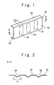
- a rib 101 includes a web 102 and flanges 103 provided at both ends of the web 102.
- a plurality of beads 104 are provided along the longitudinal direction of the web 102.
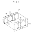
- Each of the beads 104 extends in a direction orthogonal to the longitudinal direction. Since the beads 104 are provided, an actual length L 101 of the web 102 shown in Fig. 2 is longer than an actual length L 102 of the flange 103 shown in Fig. 1 .
- the rib 101 When the rib 101 is molded by using a prepreg material including woven fabric of carbon or glass fiber, wrinkles tend to be generated at corner portions of the bead 104. This is because, since the prepreg material cannot be stretched in the direction of fiber, a difference between the actual length L 101 and the actual length L 102 cannot be absorbed.
- a method is known in which the difference between the actual length L 101 and the actual length L 102 is absorbed by forming cuts 106 in a prepreg material 105 at locations corresponding to the corner portions of the beads 104.
- Patent literature 1 Japanese Patent Publication ( JP-A-Heisei 10-258463 )
- An objective of the present invention is to provide a manufacturing method of a composite material member having less wrinkle, a manufacturing method of a wing structure of an aircraft that includes a composite material member having less wrinkle, a manufacturing method of a fuselage structure of an aircraft that includes a composite material member having less wrinkle, and a prepreg sheet laminate suitable for those manufacturing methods.
- a manufacturing method of composite material member includes a step of shaping a laminate including laminated prepreg sheets along a mold.
- the laminate includes a first layer in which fibers are oriented in single direction.
- a first surface crossing the single direction and a second surface crossing the single direction are confronted each other such that the first surface and the second surface face each other.
- the laminate Since the fibers are discontinuous at a cut between the first surface and the second surface, the laminate is easily shaped and wrinkles are hard to be generated in a composite material member to be manufactured from the laminate.
- the first layer includes a first point and a second point.
- the first point and the second point are arranged on a straight line which is parallel to the single direction and crosses the first surface and the second surface at a first intersection and a second intersection such that the first intersection and the second intersection are arranged between the first point and the second point.
- the step of shaping preferably includes a step of making the laminate to be bent such that a first flange connected to one side of a web and a second flange connected to another side of the web are formed.
- the first flange and the second flange face each other.
- the first flange is curved to be convex toward the second flange.
- the laminate preferably includes a second layer in which fibers are oriented in the single direction, in addition the first layer.
- a third surface crossing the single direction and a fourth surface crossing the single direction are confronted each other such that the third surface and the fourth surface face each other.
- the first surface and the third surface are shifted in position from each other along the single direction.
- the laminate preferably includes a third layer in which fibers are oriented in a direction which orthogonally crosses the single direction.
- a manufacturing method of wing structure of aircraft includes a step of manufacturing a spar.
- the step of manufacturing the spar includes a step of shaping a laminate including laminated prepreg sheets along a mold.
- the laminate includes a first layer in which fibers are oriented in single direction. In the first layer, a first surface crossing the single direction and a second surface crossing the single direction are confronted each other such that the first surface and the second surface face each other.
- a manufacturing method of fuselage structure of aircraft includes: a step of manufacturing a frame; and a step of manufacturing a stringer. At least one of the step of manufacturing the frame and the step of manufacturing the stringer includes a step of shaping a laminate including laminated prepreg sheets along a mold.
- the laminate includes a first layer in which fibers are oriented in single direction. In the first layer, a first surface crossing the single direction and a second surface crossing the single direction are confronted each other such that the first surface and the second surface face each other.
- a prepreg sheet laminate in another aspect of the present invention, includes a first layer in which fibers are oriented in a single direction.
- a first surface crossing the single direction and a second surface crossing the single direction are confronted each other such that the first surface and the second surface face each other.
- the prepreg sheet laminate preferably includes a second layer in which fibers are oriented in the single direction, in addition to the first layer.
- a third surface crossing the single direction and a fourth surface crossing the single direction are confronted each other such that the third surface and the fourth surface face each other.
- the first surface and the third surface are shifted in position from each other along the single direction.
- the prepreg sheet laminate preferably further includes a third layer in which fibers are oriented in a direction which orthogonally crosses the single direction.
- a manufacturing method of a composite material member having less wrinkle a manufacturing method of a wing structure of an aircraft that includes a composite material member having less wrinkle, a manufacturing method of a fuselage structure of an aircraft that includes a composite material member having less wrinkle, and a prepreg sheet laminate suitable for those manufacturing methods.
- Fig. 4 shows an aircraft 1 according to a first embodiment of the present invention.
- the aircraft 1 includes a wing 2 and a fuselage 3.
- Fig. 5 shows a wing structure 20 of the wing 2.
- the wing structure 20 includes a spar 21, a rib 22 attached to the spar 21, and a skin 23 attached to the rib 22.
- the wing 2 may be a main wing or may be a tail assembly.
- Fig. 6 shows a perspective view of the spar 21.
- the spar 21 as a composite material member is formed by composite material such as fiber reinforced plastic.
- the spar 21 includes a web 81, a flange 82 connected to one side of the web 81, and a flange 83 connected to the other side of the web 81.
- Each of the web 81, the flange 82 and the flange 83 is plate-shaped.
- the flange 82 is connected to the web 81 via a corner portion 84 extending along the longitudinal direction of the spar 21.
- the flange 83 is connected to the web 81 via a corner portion 85 extending along the longitudinal direction of the spar 21.
- the flange 82 and the flange 83 face each other.
- the flange 82 is curved to be convex toward the flange 83.
- the manufacturing method of the spar 21 includes: a step of providing a laminate 4 having a shape of a flat plate, in which prepreg sheets are laminated, a step of pre-shaping the laminate 4 along a mold, and a step of curing the pre-shaped laminate 4.
- a hot drape forming is used.
- Fig. 7 shows a method of pre-shaping the laminate 4 by using the hot drape forming.
- a shaping mold 7 has a top surface 71, a side surface 72 connected to the top surface 71 via a corner portion 74, and a side surface 73 connected to the top surface 71 via a corner portion 75.
- the top surface 71 corresponds to the web 81
- the side surface 72 corresponds to the flange 82
- the side surface 73 corresponds to the flange 83
- the corner portion 74 corresponds to the corner portion 84
- the corner portion 75 corresponds to the corner portion 85.
- the laminate 4 is placed on the top surface 71 and positioned with respect to the shaping mold 7.
- Fig.8 shows the arrangement between the laminate 4 and the shaping mold 7.
- a center line 70 of the shaping mold 7 is a straight line.
- the distance from the corner portion 74 to the center line 70 is approximately equal to the distance from the corner portion 75 to the center line 70.
- the corner portion 74 is curved to be convex toward the corner portion 75.
- the laminate 4 includes a 0 degree layer, a +45 degree layer, a -45 degree layer and a 90 degree layer. In each of the 0 degree layer, the +45 degree layer, the -45 degree layer and the 90 degree layer, fibers are oriented in single direction (unidirectionally oriented).
- Adirectionof the fibers in the 0 degree layer (0 degree direction), a direction of the fibers in the +45 degree layer (+45 degree direction), a direction of the fibers in the -45 degree layer (-45 degree direction) and a direction of the fibers in the 90 degree layer (90 degree direction) are indicated by arrows in the figure.
- the +45 degree direction obliquely crosses the 0 degree direction at the angle of +45 degree.
- the -45 degree direction obliquely crosses the 0 degree direction at the angle of -45 degree.
- the 90 degree direction crosses the 0 degree direction at the angle of 90 degree.
- the laminate 4 is positioned with respect to the shaping mold 7 such that the angle between the 0 degree direction and the center line 70 is in a range from -10 degree to +10 degree.
- the 0 degree layer is provided with cuts 4a such that when the laminate 4 is positioned with respect to the shaping mold 7, the cuts 4a cross the corner portion 74 as viewed in a direction orthogonal to the top surface 71.
- the cuts 4a cross the 0 degree direction.
- Fig. 9 shows a sectional view along the C-C cutting line of Fig. 8 .
- the laminate 4 includes a prepreg sheet 41 as the +45 degree layer, a prepreg sheet 42 as the 90 degree layer, a prepreg sheet 43 as the -45 degree layer, and a prepreg sheet 44 as the 0 degree layer.
- the prepreg sheet 44 is arranged at a side near the top surface 71, and the prepreg sheet 41 is arranged at a side far from the top surface 71.
- the prepreg sheet 42 is arranged between the prepreg sheet 41 and the prepreg sheet 43, and the prepreg sheet 43 is arranged between the prepreg sheet 42 and the prepreg sheet 44.
- the cuts 4a are provided in the prepreg sheet 44.
- the prepreg sheet 44 includes fibers which are discontinuous at the cut 4a.
- the prepreg sheet 44 has a surface 44a and a surface 44b at each cut 4a.
- the cut 4a is formed between the surface 44a and the surface 44b.
- Each of the surface 44a and the surface 44b crosses, for example, the 0 degree direction at the angle of 90 degree or approximate 90 degree.
- the approximate 90 degree is an angle in a range from 87 degree to 93 degree.
- the surface 44a and the surface 44b are confronted each other such that the surfaces face each other.
- cut surfaces of a plurality of fibers are arranged.
- the cut surfaces correspond to transverse sections of the fibers.
- a cut like the cut 4a is not provided in the prepreg sheets 41, 42 and 43.
- the cuts 4a are provided at a pitch P along the 0 degree direction. Only single cut 4a may be provided.
- the prepreg sheet 44 includes a straight line 5 parallel to the 0 degree direction. There are a point 51, a point 52, an intersection 53 and an intersection 54 on the straight line 5.
- the intersection 53 is an intersection between the straight line 5 and the surface 44a
- the intersection 54 is an intersection between the straight line 5 and the surface 44b.
- the intersection 53 and the intersection 54 are arranged between the point 51 and the point 52.
- the points 51, 52 and the intersections 53, 54 are arranged at both sides of the corner portion 74, respectively.
- an autoclave is used to perform a curing process on the pre-shaped laminate 4 under a heated and pressurized condition.
- Fig. 13 shows a spar 21 that is manufactured through the above-described pre-shaping step and curing step from the laminate 4. Since the cuts 4a are provided to the laminate 4, wrinkles are prevented to be generated in the spar 21.
- the spar 21 includes boundary planes 87 corresponding to the respective cuts 4a. At the boundary plane 87, a plurality of fibers in the prepreg sheet 44 are discontinuous.
- the boundary plane 87 crosses the corner portion 84 to be arranged in both of the flange 82 and the web 81.
- the point 51 and the point 52 are arranged in the web 81.
- the intersection 53 and the intersection 54 are arranged in the flange 82.
- the pitch P of 300 mm remarkably suppresses the generation of wrinkles.
- the curvature radius R is smaller or the necessary width of the flange is larger, the pitch P is preferred to be smaller.
- the curvature radius R, the width W and the pitch P are not limited to those values.
- the fibers in the +45 degree layer and the fibers in the -45 degree layer resist the tension parallel to the 0 degree direction. Thus, it is prevented that the spar 21 cannot achieve a desired strength due to the existence of the boundary planes 87.
- Fig. 14 shows a spar 21 that is manufactured through the above-described pre-shaping step and curing step from the laminate 4 according to the comparison example.
- a laminate 4 according to a second embodiment of the present invention is different from the laminate 4 according to the first embodiment, only in the 0 degree layer.
- the 0 degree layer according to the second embodiment corresponds to the prepreg sheet 44 according to the first embodiment to which a cut 4x parallel to the 0 degree direction is added.
- the 0 degree layer of the laminate 4 includes a prepreg sheet 44-1, aprepreg sheet 44-2, aprepreg sheet 44-3 andaprepreg sheet 44-4.
- the cut 4x is arranged between the corner portion 74 and the corner portion 75 as viewed in a direction orthogonal to the top surface 71.
- the method according to the present embodiment is effective, for example, when a laminate in which the width of web is wide is manufactured. That is, the method according to the present embodiment has an advantage of easy manufacturing as compared to a method in which a web and flanges are formed by using single large prepreg sheet with cuts. Also, the method has a merit of improving material utilization.
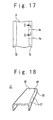
- a laminate 4 according to a third embodiment of the present invention is different from the laminate 4 according to the first embodiment of the present invention, only in a point that the cuts 4a do not cross the corner portion 74.
- Fig. 18 shows a spar 21 that is manufactured through the above-mentioned pre-shaping step and curing step from the laminate 4 in Fig. 17 .
- the boundary planes 87 corresponding to the cuts 4a are arranged in only the flange 82 and not arranged in the web 81.
- a method according to the present embodiment is effective when the curvature radius of the flange of the member exceeds 5000 mm and cut of fibers are desired to be suppressed to the minimum in order to retain the strength of the member at the maximum.
- a laminate 4 according to a fourth embodiment of the present invention corresponds to the laminate 4 according to any of the first to third embodiments, to which other layers are added.
- the laminate 4 according to the present embodiment is mirror-symmetrical with respect to a plane of symmetry, 6.
- the laminate 4 includes a prepreg sheet 45 as a 0 degree layer, a prepreg sheet 46 as a +45 degree layer, a prepreg sheet 47 and a prepreg sheet 48 as 0 degree layers, a prepreg sheet 49 as a -45 degree layer, and a prepreg sheet 50 as a 0 degree layer, in addition to the above-mentioned prepreg sheets 41 to 44.
- the prepreg sheet 44 is arranged between the prepreg sheet 41 and the symmetry plane 6.
- the prepreg sheet 47 is arranged between the prepreg sheet 44 and the symmetry plane 6.
- the prepreg sheet 45 is arranged between the prepreg sheet 44 and the prepreg sheet 47.
- the prepreg sheet 46 is arranged between the prepreg sheet 45 and the prepreg sheet 47.
- the prepreg sheet 49 is arranged between the prepreg sheet 47 and the symmetry plane 6.
- the prepreg sheet 48 is arranged between the prepreg sheet 47 and the prepreg sheet 49.
- the prepreg sheet 50 is arranged between the prepreg sheet 49 and the symmetry plane 6.
- the prepreg sheet 45 is provided with a cut 4a at a position shifted by a distance D in the 0 degree direction from the cut 4a in the prepreg sheet 44.
- the prepreg sheet 47 is provided with a cut 4a at a position shifted by the distance D in the 0 degree direction from the cut 4a in the prepreg sheet 45.
- the prepreg sheet 48 is provided with a cut 4a at a position shifted by the distance D in the 0 degree direction from the cut 4a in the prepreg sheet 47.
- the prepreg sheet 50 is provided with a cut 4a at a position shifted by the distance D in the 0 degree direction from the cut 4a in the prepreg sheet 48.
- the respective cuts 4a are provided to cross the 0 degree direction.
- a surface like the surface 44a and a surface like the surface 44b are confronted each other such that the surfaces face each other.
- the distance D is preferred to be 25 mm (1 inch) or longer. The above-mentioned shifts are intentionally provided. The distance D may be determined such that the cuts 4a of the prepreg sheets 45, 47, 48 and 50 are uniformly dispersed in the entire of the pitch of the cuts 4a in the prepreg sheet 44, or the distance D may be determined such that the cuts 4a of the prepreg sheets 44, 45, 47, 48 and 50 are uniformly dispersed in the entire of the laminate 4.
- a spar 21 is manufactured through the above-described pre-shaping step and curing step from the laminate 4 shown in Fig. 19 . Since the spar 21 includes the plurality of 0 degree layers and boundary planes 87 formed in those layer are shifted in the 0 degree direction, the strength of the spar 21 is enhanced.
- a + ⁇ degree layer may be used in place of the +45 degree layer, and a - ⁇ degree layer may be used in place of the -45 degree layer.
- fibers are oriented in single direction.
- the direction of fibers in the + ⁇ f degree layer obliquely crosses the 0 degree direction at the angle of + ⁇ degree.
- the direction of the fibers in the - ⁇ degree layer obliquely crosses the 0 degree direction at the angle of - ⁇ degree.
- 0 ⁇ 45, or 45 ⁇ 90 are oriented in single direction.
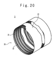
- a fuselage structure 30 of the fuselage 3 includes the frame 31 which is ring-shaped, the stringer 32 which is fixed to the frame 31, and a skin 33.
- the frame 31 includes a web 31a and flanges 31b and 31c which are connected to the web 31a.
- the web 31a corresponds to the web 81
- the flange 31b corresponds to the flange 82
- the flange 31c corresponds to the flange 83.
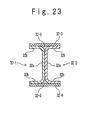
- the stringer 32 is H-shaped or I-shaped in the transverse section.
- the stringer 32 includes members 32-1 and 32-2, a top plate 32-3 having a flat-plate shape, a base plate 32-4 having a flat-plate shape, and corner portion fillers 32-5 and 32-6.
- Each of the members 32-1 and 32-2 is U-shaped or right U-shaped in the transverse section.
- Each of the members 32-1 and 32-2 includes a web 32a and two flanges 32b connected to the web 32a.
- the web 32a of the member 32-1 and the web 32a of the member 32-2 are coupled to each other such that the members 32-1 and 32-2 form a coupled body which is H-shaped or I-shaped in the transverse section.
- the top plate 32-3 and the base plate 32-4 face each other with the coupled body being arranged between them.
- the top plate 32-3 is coupled to the flanges 32b of the members 32-1 and 32-2, which are arranged on a side far from the skin 33.
- the corner portion filler 32-5 is arranged to be surrounded by the top plate 32-3, the member 32-1 and the member 32-2.
- the base plate 32-4 is coupled to the flanges 32b of the members 32-1 and 32-2, which are arranged on a side near the skin 33.
- the corner portion filler 32-6 is arranged to be surrounded by the base plate 32-4, the member 32-1 and the member 32-2.
- the base plate 32-4 is coupled to the skin 33.
- the web 32a corresponds to the web 81
- the two flanges 32b correspond to the flange 82 and the flange 83.
Landscapes
- Engineering & Computer Science (AREA)
- Mechanical Engineering (AREA)
- Chemical & Material Sciences (AREA)
- Composite Materials (AREA)
- Textile Engineering (AREA)
- Moulding By Coating Moulds (AREA)
- Casting Or Compression Moulding Of Plastics Or The Like (AREA)
- Laminated Bodies (AREA)
Abstract
Description
- The present invention relates to manufacturing methods of a composite material member, a wing structure of an aircraft and a fuselage structure of an aircraft, and a prepreg sheet laminate.
- Japanese Patent Publication (
JP-A-Heisei 10-258463 Fig. 1 , arib 101 includes aweb 102 andflanges 103 provided at both ends of theweb 102. In order to increase the rigidity of therib 101, a plurality ofbeads 104 are provided along the longitudinal direction of theweb 102. Each of thebeads 104 extends in a direction orthogonal to the longitudinal direction. Since thebeads 104 are provided, an actual length L101 of theweb 102 shown inFig. 2 is longer than an actual length L102 of theflange 103 shown inFig. 1 . - When the
rib 101 is molded by using a prepreg material including woven fabric of carbon or glass fiber, wrinkles tend to be generated at corner portions of thebead 104. This is because, since the prepreg material cannot be stretched in the direction of fiber, a difference between the actual length L101 and the actual length L102 cannot be absorbed. - As shown in
Fig. 3 , a method is known in which the difference between the actual length L101 and the actual length L102 is absorbed by formingcuts 106 in aprepreg material 105 at locations corresponding to the corner portions of thebeads 104. - Patent literature 1: Japanese Patent Publication (
JP-A-Heisei 10-258463 - An objective of the present invention is to provide a manufacturing method of a composite material member having less wrinkle, a manufacturing method of a wing structure of an aircraft that includes a composite material member having less wrinkle, a manufacturing method of a fuselage structure of an aircraft that includes a composite material member having less wrinkle, and a prepreg sheet laminate suitable for those manufacturing methods.
- In a first aspect of the present invention, a manufacturing method of composite material member includes a step of shaping a laminate including laminated prepreg sheets along a mold. The laminate includes a first layer in which fibers are oriented in single direction. In the first layer, a first surface crossing the single direction and a second surface crossing the single direction are confronted each other such that the first surface and the second surface face each other.
- Since the fibers are discontinuous at a cut between the first surface and the second surface, the laminate is easily shaped and wrinkles are hard to be generated in a composite material member to be manufactured from the laminate.
- The first layer includes a first point and a second point. Before the step of shaping, the first point and the second point are arranged on a straight line which is parallel to the single direction and crosses the first surface and the second surface at a first intersection and a second intersection such that the first intersection and the second intersection are arranged between the first point and the second point. The step of shaping preferably includes a step of making the laminate to be bent such that a first flange connected to one side of a web and a second flange connected to another side of the web are formed. The first flange and the second flange face each other. The first flange is curved to be convex toward the second flange. After the step of shaping, the first point and the second point are arranged in the web while the first intersection and the second intersection are arranged in the first flange.
- The laminate preferably includes a second layer in which fibers are oriented in the single direction, in addition the first layer. In the second layer, a third surface crossing the single direction and a fourth surface crossing the single direction are confronted each other such that the third surface and the fourth surface face each other. The first surface and the third surface are shifted in position from each other along the single direction.
- The laminate preferably includes a third layer in which fibers are oriented in a direction which orthogonally crosses the single direction.
- In another aspect of the present invention, a manufacturing method of wing structure of aircraft includes a step of manufacturing a spar. The step of manufacturing the spar includes a step of shaping a laminate including laminated prepreg sheets along a mold. The laminate includes a first layer in which fibers are oriented in single direction. In the first layer, a first surface crossing the single direction and a second surface crossing the single direction are confronted each other such that the first surface and the second surface face each other.
- In another aspect of the present invention, a manufacturing method of fuselage structure of aircraft includes: a step of manufacturing a frame; and a step of manufacturing a stringer. At least one of the step of manufacturing the frame and the step of manufacturing the stringer includes a step of shaping a laminate including laminated prepreg sheets along a mold. The laminate includes a first layer in which fibers are oriented in single direction. In the first layer, a first surface crossing the single direction and a second surface crossing the single direction are confronted each other such that the first surface and the second surface face each other.
- In another aspect of the present invention, a prepreg sheet laminate includes a first layer in which fibers are oriented in a single direction. In the first layer, a first surface crossing the single direction and a second surface crossing the single direction are confronted each other such that the first surface and the second surface face each other.
- The prepreg sheet laminate preferably includes a second layer in which fibers are oriented in the single direction, in addition to the first layer. In the second layer, a third surface crossing the single direction and a fourth surface crossing the single direction are confronted each other such that the third surface and the fourth surface face each other. The first surface and the third surface are shifted in position from each other along the single direction.
- The prepreg sheet laminate preferably further includes a third layer in which fibers are oriented in a direction which orthogonally crosses the single direction.
- According to the present invention, there are provided a manufacturing method of a composite material member having less wrinkle, a manufacturing method of a wing structure of an aircraft that includes a composite material member having less wrinkle, a manufacturing method of a fuselage structure of an aircraft that includes a composite material member having less wrinkle, and a prepreg sheet laminate suitable for those manufacturing methods.
- The above and other objects, advantages, and features of the present invention will be more apparent from the description of embodiments taken in conjunction with the accompanying drawings, in which:
-
Fig. 1 is a perspective view of a conventional composite material molded product; -
Fig. 2 is a sectional view of the composite material molded product; -
Fig. 3 is a perspective view showing another example of conventional composite material molded product; -
Fig. 4 is a top view of an aircraft according to a first embodiment of the present invention; -
Fig. 5 is a sectional view of a wing structure of the aircraft; -
Fig. 6 is a perspective view of a spar of the wing structure; -
Fig. 7 shows a step of pre-shaping a laminate; -
Fig. 8 is a top view showing an arrangement between the laminate according to the first embodiment and a shaping mold; -
Fig. 9 is a sectional view of the laminate ofFig. 8 ; -
Fig. 10 is a top view of a 0 degree layer prepreg sheet of the laminate according to the first embodiment; -
Fig. 11 is a top view showing a detailed arrangement between the laminate and the shaping mold; -
Fig. 12 shows the pre-shaped laminate; -
Fig. 13 is a perspective view of a spar according to the first embodiment; -
Fig. 14 is a perspective view of a spar according to a comparison example; -
Fig. 15 is a top view of a 0 degree layer prepreg sheet of a laminate according to a second embodiment of the present invention; -
Fig. 16 is a top view showing an arrangement between the laminate according to the second embodiment and the shaping mold; -
Fig. 17 is a top view showing an arrangement between a laminate according to a third embodiment of the present invention and the shaping mold; -
Fig. 18 is a perspective view of a spar according to the third embodiment; -
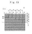
Fig. 19 is a sectional view of a laminate according to a fourth embodiment of the present invention; -
Fig. 20 is a perspective view of a fuselage structure of the aircraft; -
Fig. 21 is a sectional view of a frame of the fuselage structure; -
Fig. 22 is a perspective view of a stringer of the fuselage structure; and -
Fig. 23 is a sectional view of the stringer. - With reference to the accompanying drawings, embodiments of a composite material member, a wing structure of an aircraft, a fuselage structure of an aircraft, manufacturing methods of those and a prepreg sheet laminate according to the present invention will be described below.
-
Fig. 4 shows anaircraft 1 according to a first embodiment of the present invention. Theaircraft 1 includes awing 2 and afuselage 3.Fig. 5 shows awing structure 20 of thewing 2. Thewing structure 20 includes aspar 21, arib 22 attached to thespar 21, and askin 23 attached to therib 22. Thewing 2 may be a main wing or may be a tail assembly. -
Fig. 6 shows a perspective view of thespar 21. Thespar 21 as a composite material member is formed by composite material such as fiber reinforced plastic. Thespar 21 includes aweb 81, aflange 82 connected to one side of theweb 81, and aflange 83 connected to the other side of theweb 81. Each of theweb 81, theflange 82 and theflange 83 is plate-shaped. Theflange 82 is connected to theweb 81 via acorner portion 84 extending along the longitudinal direction of thespar 21. Theflange 83 is connected to theweb 81 via acorner portion 85 extending along the longitudinal direction of thespar 21. Theflange 82 and theflange 83 face each other. Theflange 82 is curved to be convex toward theflange 83. - A manufacturing method of the
spar 21 will be described below. The manufacturing method of thespar 21 includes: a step of providing alaminate 4 having a shape of a flat plate, in which prepreg sheets are laminated, a step of pre-shaping thelaminate 4 along a mold, and a step of curing thepre-shaped laminate 4. - In the pre-shaping step, for example, a hot drape forming is used.
Fig. 7 shows a method of pre-shaping thelaminate 4 by using the hot drape forming. A shapingmold 7 has atop surface 71, aside surface 72 connected to thetop surface 71 via acorner portion 74, and aside surface 73 connected to thetop surface 71 via acorner portion 75. Thetop surface 71 corresponds to theweb 81, theside surface 72 corresponds to theflange 82, theside surface 73 corresponds to theflange 83, thecorner portion 74 corresponds to thecorner portion 84, and thecorner portion 75 corresponds to thecorner portion 85. Thelaminate 4 is placed on thetop surface 71 and positioned with respect to the shapingmold 7. -
Fig.8 shows the arrangement between the laminate 4 and the shapingmold 7. Acenter line 70 of the shapingmold 7 is a straight line. The distance from thecorner portion 74 to thecenter line 70 is approximately equal to the distance from thecorner portion 75 to thecenter line 70. Correspondingly to the point that theflange 82 is curved to be convex toward theflange 83, thecorner portion 74 is curved to be convex toward thecorner portion 75. Thelaminate 4 includes a 0 degree layer, a +45 degree layer, a -45 degree layer and a 90 degree layer. In each of the 0 degree layer, the +45 degree layer, the -45 degree layer and the 90 degree layer, fibers are oriented in single direction (unidirectionally oriented). Adirectionof the fibers in the 0 degree layer (0 degree direction), a direction of the fibers in the +45 degree layer (+45 degree direction), a direction of the fibers in the -45 degree layer (-45 degree direction) and a direction of the fibers in the 90 degree layer (90 degree direction) are indicated by arrows in the figure. The +45 degree direction obliquely crosses the 0 degree direction at the angle of +45 degree. The -45 degree direction obliquely crosses the 0 degree direction at the angle of -45 degree. The 90 degree direction crosses the 0 degree direction at the angle of 90 degree. For example, thelaminate 4 is positioned with respect to the shapingmold 7 such that the angle between the 0 degree direction and thecenter line 70 is in a range from -10 degree to +10 degree. - The 0 degree layer is provided with
cuts 4a such that when thelaminate 4 is positioned with respect to the shapingmold 7, thecuts 4a cross thecorner portion 74 as viewed in a direction orthogonal to thetop surface 71. Thecuts 4a cross the 0 degree direction. -
Fig. 9 shows a sectional view along the C-C cutting line ofFig. 8 . Thelaminate 4 includes aprepreg sheet 41 as the +45 degree layer, aprepreg sheet 42 as the 90 degree layer, aprepreg sheet 43 as the -45 degree layer, and aprepreg sheet 44 as the 0 degree layer. Theprepreg sheet 44 is arranged at a side near thetop surface 71, and theprepreg sheet 41 is arranged at a side far from thetop surface 71. Theprepreg sheet 42 is arranged between theprepreg sheet 41 and theprepreg sheet 43, and theprepreg sheet 43 is arranged between theprepreg sheet 42 and theprepreg sheet 44. Thecuts 4a are provided in theprepreg sheet 44. Theprepreg sheet 44 includes fibers which are discontinuous at thecut 4a. Theprepreg sheet 44 has asurface 44a and asurface 44b at eachcut 4a. Thecut 4a is formed between thesurface 44a and thesurface 44b. Each of thesurface 44a and thesurface 44b crosses, for example, the 0 degree direction at the angle of 90 degree or approximate 90 degree. The approximate 90 degree is an angle in a range from 87 degree to 93 degree. Thesurface 44a and thesurface 44b are confronted each other such that the surfaces face each other. At each of thesurface 44a and thesurface 44b, cut surfaces of a plurality of fibers are arranged. The cut surfaces correspond to transverse sections of the fibers. A cut like thecut 4a is not provided in theprepreg sheets - With reference to
Fig. 10 , when a plurality ofcuts 4a are provided to theprepreg sheet 44, thecuts 4a are provided at a pitch P along the 0 degree direction. Onlysingle cut 4a may be provided. - With reference to
Fig. 11 , the arrangement between the shapingmold 7 and thelaminate 4 shown inFig. 8 will be described in detail. Theprepreg sheet 44 includes astraight line 5 parallel to the 0 degree direction. There are apoint 51, apoint 52, an intersection 53 and an intersection 54 on thestraight line 5. The intersection 53 is an intersection between thestraight line 5 and thesurface 44a, and the intersection 54 is an intersection between thestraight line 5 and thesurface 44b. The intersection 53 and the intersection 54 are arranged between thepoint 51 and thepoint 52. Thepoints corner portion 74, respectively. - With reference to
Fig. 7 , after thelaminate 4 and the shapingmold 7 are covered with afilm 9, the inside of thefilm 9 is vacuumed while heating thelaminate 4. As a result, thelaminate 4 is made to be bent along thecorner portion 74 and thecorner portion 75. Consequently, theweb 81, theflange 82, theflange 83, thecorner portion 84 and thecorner portion 85 are formed as shown inFig. 12 . - A portion of the
laminate 4, which is to be theflange 82, is made to be curved to form theflange 82. At this time, tension along thestraight line 5 is applied to the portion to be theflange 82. Since the fibers arranged on thestraight line 5 are discontinuous at thecut 4a, thelaminate 4 is easily shaped along the shapingmold 7 and wrinkles are hard to be generated in thelaminate 4. - Next, in the curing step, an autoclave is used to perform a curing process on the
pre-shaped laminate 4 under a heated and pressurized condition. -
Fig. 13 shows aspar 21 that is manufactured through the above-described pre-shaping step and curing step from thelaminate 4. Since thecuts 4a are provided to thelaminate 4, wrinkles are prevented to be generated in thespar 21. Thespar 21 includes boundary planes 87 corresponding to therespective cuts 4a. At theboundary plane 87, a plurality of fibers in theprepreg sheet 44 are discontinuous. Theboundary plane 87 crosses thecorner portion 84 to be arranged in both of theflange 82 and theweb 81. Thepoint 51 and thepoint 52 are arranged in theweb 81. The intersection 53 and the intersection 54 are arranged in theflange 82. - When a radius of curvature, R of the
flange 82 is from 50000 mm to 75000 mm and a width W of theflange 82 is 150 mm or less, the pitch P of 300 mm remarkably suppresses the generation of wrinkles. As the curvature radius R is smaller or the necessary width of the flange is larger, the pitch P is preferred to be smaller. However, the curvature radius R, the width W and the pitch P are not limited to those values. - After the curing, the fibers in the +45 degree layer and the fibers in the -45 degree layer resist the tension parallel to the 0 degree direction. Thus, it is prevented that the
spar 21 cannot achieve a desired strength due to the existence of the boundary planes 87. - The above-described
cuts 4a are not provided to alaminate 4 according to a comparison example of the present invention.Fig. 14 shows aspar 21 that is manufactured through the above-described pre-shaping step and curing step from thelaminate 4 according to the comparison example. When a portion of thelaminate 4, which is to be theflange 82, is made to be curved to form theflange 82, tension is applied to the portion to be flange 82 along the fibers in the 0 degree layer. Since the fibers in the 0 degree layer resist the tension, as shown inFig. 14 ,wrinkles 86 are generated in theweb 81. Since thewrinkles 86 deteriorate the strength of thespar 21, the number of thewrinkles 86 is preferred to be small. - A
laminate 4 according to a second embodiment of the present invention is different from thelaminate 4 according to the first embodiment, only in the 0 degree layer. With reference toFig. 15 , the 0 degree layer according to the second embodiment corresponds to theprepreg sheet 44 according to the first embodiment to which acut 4x parallel to the 0 degree direction is added. In this case, the 0 degree layer of thelaminate 4 includes a prepreg sheet 44-1, aprepreg sheet 44-2, aprepreg sheet 44-3 andaprepreg sheet 44-4. With reference toFig. 16 , thecut 4x is arranged between thecorner portion 74 and thecorner portion 75 as viewed in a direction orthogonal to thetop surface 71. Since thecut 4x disappears when the resin of the prepreg sheet is melted and re-solidified, there is no boundary plane corresponding to thecut 4x in a spar that is manufactured through the above-mentioned pre-shaping step and curing step from thelaminate 4 according to the present embodiment. The method according to the present embodiment is effective, for example, when a laminate in which the width of web is wide is manufactured. That is, the method according to the present embodiment has an advantage of easy manufacturing as compared to a method in which a web and flanges are formed by using single large prepreg sheet with cuts. Also, the method has a merit of improving material utilization. - With reference to
Fig. 17 , alaminate 4 according to a third embodiment of the present invention is different from thelaminate 4 according to the first embodiment of the present invention, only in a point that thecuts 4a do not cross thecorner portion 74.Fig. 18 shows aspar 21 that is manufactured through the above-mentioned pre-shaping step and curing step from thelaminate 4 inFig. 17 . As shown inFig. 18 , the boundary planes 87 corresponding to thecuts 4a are arranged in only theflange 82 and not arranged in theweb 81. A method according to the present embodiment is effective when the curvature radius of the flange of the member exceeds 5000 mm and cut of fibers are desired to be suppressed to the minimum in order to retain the strength of the member at the maximum. - A
laminate 4 according to a fourth embodiment of the present invention corresponds to thelaminate 4 according to any of the first to third embodiments, to which other layers are added. With reference toFig. 19 , thelaminate 4 according to the present embodiment is mirror-symmetrical with respect to a plane of symmetry, 6. Thelaminate 4 includes aprepreg sheet 45 as a 0 degree layer, aprepreg sheet 46 as a +45 degree layer, aprepreg sheet 47 and aprepreg sheet 48 as 0 degree layers, aprepreg sheet 49 as a -45 degree layer, and aprepreg sheet 50 as a 0 degree layer, in addition to the above-mentionedprepreg sheets 41 to 44. Theprepreg sheet 44 is arranged between theprepreg sheet 41 and the symmetry plane 6. Theprepreg sheet 47 is arranged between theprepreg sheet 44 and the symmetry plane 6. Theprepreg sheet 45 is arranged between theprepreg sheet 44 and theprepreg sheet 47. Theprepreg sheet 46 is arranged between theprepreg sheet 45 and theprepreg sheet 47. Theprepreg sheet 49 is arranged between theprepreg sheet 47 and the symmetry plane 6. Theprepreg sheet 48 is arranged between theprepreg sheet 47 and theprepreg sheet 49. Theprepreg sheet 50 is arranged between theprepreg sheet 49 and the symmetry plane 6. - The
prepreg sheet 45 is provided with acut 4a at a position shifted by a distance D in the 0 degree direction from thecut 4a in theprepreg sheet 44. Theprepreg sheet 47 is provided with acut 4a at a position shifted by the distance D in the 0 degree direction from thecut 4a in theprepreg sheet 45. Theprepreg sheet 48 is provided with acut 4a at a position shifted by the distance D in the 0 degree direction from thecut 4a in theprepreg sheet 47. Theprepreg sheet 50 is provided with acut 4a at a position shifted by the distance D in the 0 degree direction from thecut 4a in theprepreg sheet 48. Therespective cuts 4a are provided to cross the 0 degree direction. In thecut 4a of each of theprepreg sheet 45, theprepreg sheet 47, theprepreg sheet 48 and theprepreg sheet 50, a surface like thesurface 44a and a surface like thesurface 44b are confronted each other such that the surfaces face each other. The distance D is preferred to be 25 mm (1 inch) or longer. The above-mentioned shifts are intentionally provided. The distance D may be determined such that thecuts 4a of theprepreg sheets cuts 4a in theprepreg sheet 44, or the distance D may be determined such that thecuts 4a of theprepreg sheets laminate 4. - A
spar 21 is manufactured through the above-described pre-shaping step and curing step from thelaminate 4 shown inFig. 19 . Since thespar 21 includes the plurality of 0 degree layers andboundary planes 87 formed in those layer are shifted in the 0 degree direction, the strength of thespar 21 is enhanced. - In the above-mentioned respective embodiments, a +θ degree layer may be used in place of the +45 degree layer, and a -θ degree layer may be used in place of the -45 degree layer. In each of the +θ degree layer and the -θ degree layer, fibers are oriented in single direction. The direction of fibers in the +θf degree layer obliquely crosses the 0 degree direction at the angle of +θ degree. The direction of the fibers in the -θ degree layer obliquely crosses the 0 degree direction at the angle of -θ degree. Here, 0<θ<45, or 45<θ<90.
- The manufacturing methods according to the above-mentioned embodiments can be used to manufacture a
frame 31 and astringer 32 as composite material members. With reference toFig. 20 , afuselage structure 30 of thefuselage 3 includes theframe 31 which is ring-shaped, thestringer 32 which is fixed to theframe 31, and askin 33. As shown inFig. 21 , theframe 31 includes aweb 31a andflanges web 31a. Theweb 31a corresponds to theweb 81, theflange 31b corresponds to theflange 82, and theflange 31c corresponds to theflange 83. As shown inFig. 22 , thestringer 32 is H-shaped or I-shaped in the transverse section. As shown inFig. 23 , thestringer 32 includes members 32-1 and 32-2, a top plate 32-3 having a flat-plate shape, a base plate 32-4 having a flat-plate shape, and corner portion fillers 32-5 and 32-6. Each of the members 32-1 and 32-2 is U-shaped or right U-shaped in the transverse section. Each of the members 32-1 and 32-2 includes aweb 32a and twoflanges 32b connected to theweb 32a. Theweb 32a of the member 32-1 and theweb 32a of the member 32-2 are coupled to each other such that the members 32-1 and 32-2 form a coupled body which is H-shaped or I-shaped in the transverse section. The top plate 32-3 and the base plate 32-4 face each other with the coupled body being arranged between them. The top plate 32-3 is coupled to theflanges 32b of the members 32-1 and 32-2, which are arranged on a side far from theskin 33. The corner portion filler 32-5 is arranged to be surrounded by the top plate 32-3, the member 32-1 and the member 32-2. The base plate 32-4 is coupled to theflanges 32b of the members 32-1 and 32-2, which are arranged on a side near theskin 33. The corner portion filler 32-6 is arranged to be surrounded by the base plate 32-4, the member 32-1 and the member 32-2. The base plate 32-4 is coupled to theskin 33. With respect to each of the members 32-1 and 32-2, theweb 32a corresponds to theweb 81, and the twoflanges 32b correspond to theflange 82 and theflange 83. - The present invention has been described with reference to the embodiments; however, the present invention is not limited to the above embodiments. Various modifications can be applied to the above embodiments. For example, the above embodiments can be combined with each other.
Claims (9)
- A manufacturing method of composite material member comprising a step of shaping a laminate including laminated prepreg sheets along a mold,
wherein said laminate includes a first layer in which fibers are oriented in single direction, and
in said first layer, a first surface crossing said single direction and a second surface crossing said single direction are confronted each other such that said first surface and said second surface face each other. - The manufacturing method of composite material member according to claim 1, wherein said first layer includes a first point and a second point,
before said step of shaping, said first point and said second point are arranged on a straight line which is parallel to said single direction and crosses said first surface and said second surface at a first intersection and a second intersection such that said first intersection and said second intersection are arranged between said first point and said second point,
said step of shaping includes a step of making said laminate to be bent such that a first flange connected to one side of a web and a second flange connected to another side of said web are formed,
said first flange and said second flange face each other,
said first flange is curved to be convex toward said second flange, and
after said step of shaping, said first point and said second point are arranged in said web while said first intersection and said second intersection are arranged in said first flange. - The manufacturing method of composite material member according to claim 1 or 2, wherein said laminate includes a second layer in which fibers are oriented in said single direction,
in said second layer, a third surface crossing said single direction and a fourth surface crossing said single direction are confronted each other such that said third surface and said fourth surface face each other, and
said first surface and said third surface are shifted in position from each other along said single direction. - The manufacturing method of composite material member according to any of claims 1 to 3, wherein said laminate includes a third layer in which fibers are oriented in a direction which orthogonally crosses said single direction.
- A manufacturing method of wing structure of aircraft comprising a step of manufacturing a spar,
wherein said step of manufacturing said spar includes a step of shaping a laminate including laminated prepreg sheets along a mold,
said laminate includes a first layer in which fibers are oriented in single direction, and
in said first layer, a first surface crossing said single direction and a second surface crossing said single direction are confronted each other such that said first surface and said second surface face each other. - A manufacturing method of fuselage structure of aircraft comprising:a step of manufacturing a frame; anda step of manufacturing a stringer,wherein at least one of said step of manufacturing said frame and said step of manufacturing said stringer includes a step of shaping a laminate including laminated prepreg sheets along a mold,said laminate includes a first layer in which fibers are oriented in single direction, andin said first layer, a first surface crossing said single direction and a second surface crossing said single direction are confronted each other such that said first surface and said second surface face each other.
- A prepreg sheet laminate comprising a first layer in which fibers are oriented in a single direction,
wherein in said first layer, a first surface crossing said single direction and a second surface crossing said single direction are confronted each other such that said first surface and said second surface face each other. - The prepreg sheet laminate according to claim 7, further comprising a second layer in which fibers are oriented in said single direction,
wherein in said second layer, a third surface crossing said single direction and a fourth surface crossing said single direction are confronted each other such that said third surface and said fourth surface face each other, and
said first surface and said third surface are shifted in position from each other along said single direction. - The prepreg sheet laminate according to claim 7 or 8, further comprising a third layer in which fibers are oriented in a direction which orthogonally crosses said single direction.
Applications Claiming Priority (1)
| Application Number | Priority Date | Filing Date | Title |
|---|---|---|---|
| PCT/JP2009/059985 WO2010140205A1 (en) | 2009-06-01 | 2009-06-01 | Method for manufacturing composite material member and laminated body of prepreg sheet |
Publications (2)
| Publication Number | Publication Date |
|---|---|
| EP2439058A1 true EP2439058A1 (en) | 2012-04-11 |
| EP2439058A4 EP2439058A4 (en) | 2017-12-13 |
Family
ID=43297351
Family Applications (1)
| Application Number | Title | Priority Date | Filing Date |
|---|---|---|---|
| EP09845490.3A Withdrawn EP2439058A4 (en) | 2009-06-01 | 2009-06-01 | Method for manufacturing composite material member and laminated body of prepreg sheet |
Country Status (8)
| Country | Link |
|---|---|
| US (1) | US8790566B2 (en) |
| EP (1) | EP2439058A4 (en) |
| KR (1) | KR101353112B1 (en) |
| CN (1) | CN102395458A (en) |
| BR (1) | BRPI0924434A2 (en) |
| CA (1) | CA2760968C (en) |
| RU (1) | RU2492049C2 (en) |
| WO (1) | WO2010140205A1 (en) |
Families Citing this family (11)
| Publication number | Priority date | Publication date | Assignee | Title |
|---|---|---|---|---|
| US20140255646A1 (en) | 2013-03-08 | 2014-09-11 | The Boeing Company | Forming Composite Features Using Steered Discontinuous Fiber Pre-Preg |
| US20150203187A1 (en) * | 2013-04-02 | 2015-07-23 | The Boeing Company | Continuously Curved Spar and Method of Manufacturing |
| EP2910365B1 (en) * | 2014-02-21 | 2017-04-26 | Airbus Operations GmbH | Composite structural element and torsion box |
| US9855721B2 (en) * | 2014-09-25 | 2018-01-02 | The Boeing Company | Nonwoven decorative laminates and methods of making the same |
| CN107148388B (en) * | 2014-10-30 | 2019-08-16 | 印刷包装国际有限责任公司 | carton with handle |
| DE102016109284B3 (en) | 2016-05-20 | 2017-03-23 | Cotesa Gmbh | Arched fiber composite preform and method for producing curved profiles |
| JP6722369B2 (en) * | 2018-03-05 | 2020-07-15 | 日本飛行機株式会社 | Method for forming honeycomb sandwich composite |
| JP7034846B2 (en) * | 2018-06-15 | 2022-03-14 | 三菱重工業株式会社 | Mold for prepreg laminating and prepreg laminating method |
| WO2021186718A1 (en) * | 2020-03-19 | 2021-09-23 | 三菱重工業株式会社 | Support body and support body mounting method |
| CN113858649B (en) * | 2021-10-12 | 2023-04-25 | 山东交通学院 | Vehicle-mounted light composite material frame for bearing and preparation method thereof |
| CN116494558B (en) * | 2023-03-22 | 2025-11-18 | 中建材(上海)航空技术有限公司 | Molding method with curvature structure |
Family Cites Families (12)
| Publication number | Priority date | Publication date | Assignee | Title |
|---|---|---|---|---|
| US5173314A (en) | 1989-08-28 | 1992-12-22 | Fuji Jukogyo Kabushiki Kaisha | Apparatus for bending and forming a composite material sheet |
| JP2765981B2 (en) | 1989-08-28 | 1998-06-18 | 富士重工業株式会社 | Method and apparatus for bending composite material |
| JPH0383642A (en) | 1989-08-28 | 1991-04-09 | Toppan Printing Co Ltd | Decorative panel and preparation thereof |
| JP3812960B2 (en) * | 1995-04-07 | 2006-08-23 | 三井化学株式会社 | Corrugated pipe fitting |
| JPH10258463A (en) * | 1997-03-19 | 1998-09-29 | Fuji Heavy Ind Ltd | Composite small bone and molding method |
| KR19980074508A (en) * | 1997-03-25 | 1998-11-05 | 이대원 | How to manufacture louver for aircraft engine |
| RU2144486C1 (en) | 1999-07-06 | 2000-01-20 | Закрытое акционерное общество "Интеллект" | Flying vehicle frame |
| JP2003000780A (en) | 2001-06-25 | 2003-01-07 | Sumitomo Rubber Ind Ltd | Manufacturing method of golf club shaft made of fiber reinforced resin and golf club shaft made of fiber reinforced resin |
| JP4522796B2 (en) * | 2004-09-06 | 2010-08-11 | 本田技研工業株式会社 | Manufacturing method of fiber reinforced composite material annular structure and annular frame for aircraft fuselage comprising the structure |
| JP2007253441A (en) | 2006-03-23 | 2007-10-04 | Shin Meiwa Ind Co Ltd | Prepreg laminate molding apparatus and molding method |
| JP5161432B2 (en) | 2006-05-01 | 2013-03-13 | 三菱重工業株式会社 | Method for forming composite material structural member |
| GB2438715B (en) * | 2006-05-22 | 2011-07-20 | Advanced Composites Group Ltd | Moulding materials |
-
2009
- 2009-06-01 KR KR1020117026373A patent/KR101353112B1/en not_active Expired - Fee Related
- 2009-06-01 BR BRPI0924434A patent/BRPI0924434A2/en not_active Application Discontinuation
- 2009-06-01 CN CN2009801587392A patent/CN102395458A/en active Pending
- 2009-06-01 RU RU2011145333/05A patent/RU2492049C2/en active
- 2009-06-01 US US13/264,014 patent/US8790566B2/en active Active
- 2009-06-01 CA CA2760968A patent/CA2760968C/en active Active
- 2009-06-01 EP EP09845490.3A patent/EP2439058A4/en not_active Withdrawn
- 2009-06-01 WO PCT/JP2009/059985 patent/WO2010140205A1/en not_active Ceased
Non-Patent Citations (1)
| Title |
|---|
| See references of WO2010140205A1 * |
Also Published As
| Publication number | Publication date |
|---|---|
| EP2439058A4 (en) | 2017-12-13 |
| US20120027989A1 (en) | 2012-02-02 |
| US8790566B2 (en) | 2014-07-29 |
| RU2492049C2 (en) | 2013-09-10 |
| CN102395458A (en) | 2012-03-28 |
| CA2760968C (en) | 2014-11-18 |
| CA2760968A1 (en) | 2010-12-09 |
| BRPI0924434A2 (en) | 2016-01-26 |
| WO2010140205A1 (en) | 2010-12-09 |
| KR20120016227A (en) | 2012-02-23 |
| RU2011145333A (en) | 2013-05-20 |
| KR101353112B1 (en) | 2014-01-17 |
Similar Documents
| Publication | Publication Date | Title |
|---|---|---|
| CA2760968C (en) | Manufacturing method of composite material member and prepreg sheet laminate | |
| EP2227376B1 (en) | Contoured composite parts | |
| KR100960837B1 (en) | Molding method of structural member made of composite material and structural member made of composite material | |
| EP1311426B1 (en) | Composite material support structures with sinusoidal webs and method of fabricating same | |
| US9724891B2 (en) | Bead-stiffened composite parts | |
| CN111452947A (en) | Shaped composite stringer | |
| CN114801259B (en) | Preparation method of interlocking bidirectional grid structure reinforced foam sandwich composite material | |
| JP6732626B2 (en) | Corner tension fitting | |
| JP5180606B2 (en) | Method for manufacturing composite member and laminate of prepreg sheet | |
| JP4459401B2 (en) | Composite beam forming method | |
| US20200114590A1 (en) | Method of producing composite laminate, method of producing fiber-reinforced composite material molded product, and fiber-reinforced composite material molded product | |
| JP7240559B2 (en) | Manufacturing method for intermediate products of aircraft parts and aircraft parts | |
| EP2888095B1 (en) | A reinforced structure and a method for manufacturing a reinforced structure | |
| AU2018205159A1 (en) | Method for making a hat stiffener pre-form with under-cut chamfered flange | |
| TWI391234B (en) | A manufacturing method of a composite member and a laminate of a prepreg sheet | |
| JP7708734B2 (en) | Reinforcing member, structural member, and manufacturing method thereof | |
| US11772344B2 (en) | Product with an array of core elements or voids and interposed sheets and methods for forming such a product | |
| JP2011093329A (en) | Method for molding structural member formed of composite material |
Legal Events
| Date | Code | Title | Description |
|---|---|---|---|
| PUAI | Public reference made under article 153(3) epc to a published international application that has entered the european phase |
Free format text: ORIGINAL CODE: 0009012 |
|
| 17P | Request for examination filed |
Effective date: 20111013 |
|
| AK | Designated contracting states |
Kind code of ref document: A1 Designated state(s): AT BE BG CH CY CZ DE DK EE ES FI FR GB GR HR HU IE IS IT LI LT LU LV MC MK MT NL NO PL PT RO SE SI SK TR |
|
| DAX | Request for extension of the european patent (deleted) | ||
| RA4 | Supplementary search report drawn up and despatched (corrected) |
Effective date: 20171113 |
|
| RIC1 | Information provided on ipc code assigned before grant |
Ipc: B29C 43/10 20060101ALI20171107BHEP Ipc: B29C 70/06 20060101AFI20171107BHEP |
|
| STAA | Information on the status of an ep patent application or granted ep patent |
Free format text: STATUS: THE APPLICATION HAS BEEN WITHDRAWN |
|
| 18W | Application withdrawn |
Effective date: 20180528 |