EP2438973A1 - Separator for separating solids from liquids, particularly high viscosity liquids - Google Patents
Separator for separating solids from liquids, particularly high viscosity liquids Download PDFInfo
- Publication number
- EP2438973A1 EP2438973A1 EP11008091A EP11008091A EP2438973A1 EP 2438973 A1 EP2438973 A1 EP 2438973A1 EP 11008091 A EP11008091 A EP 11008091A EP 11008091 A EP11008091 A EP 11008091A EP 2438973 A1 EP2438973 A1 EP 2438973A1
- Authority
- EP
- European Patent Office
- Prior art keywords
- filter
- core element
- sliding
- sliding elements
- product
- Prior art date
- Legal status (The legal status is an assumption and is not a legal conclusion. Google has not performed a legal analysis and makes no representation as to the accuracy of the status listed.)
- Withdrawn
Links
- 239000007788 liquid Substances 0.000 title claims description 22
- 239000007787 solid Substances 0.000 title claims description 19
- 238000007790 scraping Methods 0.000 claims description 5
- 239000002184 metal Substances 0.000 claims description 2
- 238000007599 discharging Methods 0.000 claims 2
- 230000005855 radiation Effects 0.000 claims 1
- 239000000047 product Substances 0.000 description 54
- 238000000926 separation method Methods 0.000 description 33
- 239000002245 particle Substances 0.000 description 18
- 239000012065 filter cake Substances 0.000 description 9
- 239000011295 pitch Substances 0.000 description 7
- 238000004140 cleaning Methods 0.000 description 5
- 230000008719 thickening Effects 0.000 description 5
- 230000033001 locomotion Effects 0.000 description 4
- 238000011161 development Methods 0.000 description 3
- 230000018109 developmental process Effects 0.000 description 3
- 238000009434 installation Methods 0.000 description 3
- XLYOFNOQVPJJNP-UHFFFAOYSA-N water Substances O XLYOFNOQVPJJNP-UHFFFAOYSA-N 0.000 description 3
- 230000004323 axial length Effects 0.000 description 2
- 238000011109 contamination Methods 0.000 description 2
- 230000007423 decrease Effects 0.000 description 2
- 230000001419 dependent effect Effects 0.000 description 2
- 239000000463 material Substances 0.000 description 2
- 239000000203 mixture Substances 0.000 description 2
- 230000000750 progressive effect Effects 0.000 description 2
- 239000010802 sludge Substances 0.000 description 2
- 239000002351 wastewater Substances 0.000 description 2
- 241001674044 Blattodea Species 0.000 description 1
- 238000005452 bending Methods 0.000 description 1
- 230000001680 brushing effect Effects 0.000 description 1
- 238000006243 chemical reaction Methods 0.000 description 1
- 239000007795 chemical reaction product Substances 0.000 description 1
- 230000001427 coherent effect Effects 0.000 description 1
- 238000010276 construction Methods 0.000 description 1
- 230000003247 decreasing effect Effects 0.000 description 1
- 230000006866 deterioration Effects 0.000 description 1
- 238000005516 engineering process Methods 0.000 description 1
- 239000000706 filtrate Substances 0.000 description 1
- 238000001914 filtration Methods 0.000 description 1
- 230000010006 flight Effects 0.000 description 1
- 230000005484 gravity Effects 0.000 description 1
- 238000004519 manufacturing process Methods 0.000 description 1
- 238000005192 partition Methods 0.000 description 1
- 230000036316 preload Effects 0.000 description 1
- 230000002028 premature Effects 0.000 description 1
- 235000014059 processed cheese Nutrition 0.000 description 1
- 239000012264 purified product Substances 0.000 description 1
- 239000010865 sewage Substances 0.000 description 1
- 239000007858 starting material Substances 0.000 description 1
Images


Classifications
-
- B—PERFORMING OPERATIONS; TRANSPORTING
- B01—PHYSICAL OR CHEMICAL PROCESSES OR APPARATUS IN GENERAL
- B01D—SEPARATION
- B01D29/00—Filters with filtering elements stationary during filtration, e.g. pressure or suction filters, not covered by groups B01D24/00 - B01D27/00; Filtering elements therefor
- B01D29/11—Filters with filtering elements stationary during filtration, e.g. pressure or suction filters, not covered by groups B01D24/00 - B01D27/00; Filtering elements therefor with bag, cage, hose, tube, sleeve or like filtering elements
- B01D29/117—Filters with filtering elements stationary during filtration, e.g. pressure or suction filters, not covered by groups B01D24/00 - B01D27/00; Filtering elements therefor with bag, cage, hose, tube, sleeve or like filtering elements arranged for outward flow filtration
- B01D29/118—Filters with filtering elements stationary during filtration, e.g. pressure or suction filters, not covered by groups B01D24/00 - B01D27/00; Filtering elements therefor with bag, cage, hose, tube, sleeve or like filtering elements arranged for outward flow filtration open-ended
-
- B—PERFORMING OPERATIONS; TRANSPORTING
- B01—PHYSICAL OR CHEMICAL PROCESSES OR APPARATUS IN GENERAL
- B01D—SEPARATION
- B01D29/00—Filters with filtering elements stationary during filtration, e.g. pressure or suction filters, not covered by groups B01D24/00 - B01D27/00; Filtering elements therefor
- B01D29/62—Regenerating the filter material in the filter
- B01D29/64—Regenerating the filter material in the filter by scrapers, brushes, nozzles, or the like, acting on the cake side of the filtering element
- B01D29/6469—Regenerating the filter material in the filter by scrapers, brushes, nozzles, or the like, acting on the cake side of the filtering element scrapers
- B01D29/6476—Regenerating the filter material in the filter by scrapers, brushes, nozzles, or the like, acting on the cake side of the filtering element scrapers with a rotary movement with respect to the filtering element
-
- B—PERFORMING OPERATIONS; TRANSPORTING
- B30—PRESSES
- B30B—PRESSES IN GENERAL
- B30B9/00—Presses specially adapted for particular purposes
- B30B9/02—Presses specially adapted for particular purposes for squeezing-out liquid from liquid-containing material, e.g. juice from fruits, oil from oil-containing material
- B30B9/12—Presses specially adapted for particular purposes for squeezing-out liquid from liquid-containing material, e.g. juice from fruits, oil from oil-containing material using pressing worms or screws co-operating with a permeable casing
- B30B9/121—Screw constructions
Definitions
- the invention relates to a separator for the separation of solids from in particular highly viscous liquids, according to the preamble of claim 1 or 3.
- the patent DE 34 20 18 shows a continuously operating filter press with a plurality of cylindrical filter elements, in the interior of each a rotatable Schrautaenplanetaryl or spiral is arranged.
- the product to be filtered is thus guided by means of the spiral from top to bottom axially along the filter surface and separated part of the solids contained therein.
- the separation product is precipitated as a filter cake.
- Disadvantage is the low separation efficiency, since the spirals are continuous and uninterrupted and therefore too much good product is eliminated together with the separation product from the filter press.
- the filter cake on the filter surface is very advantageously divided into several separate sector-shaped partial surfaces, which can be removed very easily, without special blower with the aid of the scraper of the filter surface.
- disadvantage is that only a single scraper on each side of the filter surface is provided, which of course brings a significant loss of separation efficiency with it, since the filter cake builds up constantly where just the scraper is not working.
- the scraped off by the scraper filter cake falls uncontrollably back into the liquid to be purified, so that it is only concentrated in total, but not with a gradual or constant increase in the solids concentration towards the outlet, resulting in a further reduction of the separation efficiency.
- the DE 39 27 707 A1 discloses a filter centrifuge comprising a cylindrical drum rotatably mounted within a centrifugal housing, whose jacket is perforated like a sieve and covered with a filter.
- An axially parallel paring knife which can be swiveled into a working position just in front of the filter surface and can be advanced over the entire height of the drum, is followed by a mechanical scraper, which is pressed resiliently against the surface of the filter.
- two rows of scraper blades may be oblique to the direction of rotation of the drum.
- the filter cake separated by the two rows of scraper flakes falls uncontrollably back into the liquid to be purified, so that it is only concentrated overall, but not with a gradual or constant increase in the solids concentration towards the outlet , which leads to a reduction in the separation efficiency.
- Another embodiment provides a kind of disc harrow whose discs are inclined to the direction of the drum, with the aforementioned disadvantages.
- Yet another embodiment provides a resilient spiral as a scraper, but has the disadvantage that the spiral is continuous and uninterrupted and therefore too much good product is eliminated together with the separation product from the filter centrifuge, so that the separation efficiency is reduced.
- the device of DE 198 52 119 C1 It can be used in sewage treatment plants and is used to separate waste water from wastewater laden with solids, especially on ships.
- the solution consists in that a separation device has a hollow shaft, at the ends in the direction of the lower plenum a, the hollow shaft inside appropriately trained, rotatable screw connects, which is guided over the screw flights in a support bearing the partition, and the hollow shaft circumferentially brushing which are enclosed by a Feinsiebzylinder, wherein either the hollow shaft rotatable and the Feinsiebzylinder are fixed and vice versa, and the screw conveyor is connected to either the rotatable hollow shaft or the rotary fine screen cylinder, and the upper plenum via openings, the interior of the hollow shaft Disadvantage is the low separation efficiency, since the plurality of tightly packed spiral brushes act almost as a continuous and continuous spiral and therefore from de m dirty water is filtered out too little clean water before the dirty water with a slightly higher concentration of dirt is excreted from the device again
- WO 2010/070112 A1 in processed cheese making generally discloses the basic principle of a ring filter having a core member rotating therein and having scrapers on its outer periphery which move along the inner circumference of the filter surface.
- the disadvantage is that the scrapers scraping along the inner circumference of the filter surface, ie the so-called rake angle between the scraper and the vertical normal to the filter surface is negative, wherein the Schabewinkel between scraper and filter surface is greater than or equal to 90 °. This scraping forces the smaller solids to be separated into the holes of the filter, resulting in premature filter interlock and decreased pump power.
- the larger solids to be separated are not divided into smaller parts and discharged downwards, but remain for too long on the surface of the filter in the area of the scraper, so that this too leads to an early filter interlock and decrease the pump power, but also to an increased driving power of the rotary motor for the core element. Overall, thus the separation efficiency is reduced.
- this increase in the separation efficiency should take place in a shorter separation time, and the separation device should not be more costly than in the prior art.
- the present invention differs on the one hand from the DE 10 2008 063 972 A1 respectively.
- WO 2010/070112 A1 in that in the operating state, the sliding elements with the tangential of the filter inner wall form a cutting angle between 0 ° and 90 °, and with the vertical normal to the filter inner wall a positive Abtragewinkel.
- the scrapers form at the nearest DE 10 2008 063 972 A1 or WO 20101070112 A1 with the tangential of the filter inner wall a Schabewinkel greater than 90 °, and with the vertical normal to the filter inner wall a negative Abtragewinkel.
- the present invention further differs from the DE 10 2008 063 972 A1 respectively.
- WO 2010/070112 A1 in that a special promotion of the highly viscous liquid to be filtered by the special arrangement of the sliding elements takes place, because they are arranged approximately helically, so as to achieve a forced flow of the highly viscous liquid to be filtered in the direction of the discharge opening for the separation product.
- the sliding elements are thus arranged one behind the other along the longitudinal axis of the shell of the core element on at least one imaginary helical line and have between them a distance in the axial and / or circumferential direction of the core element through which liquid to be purified can flow.
- adjacent sliding elements overlap in the circumferential direction of the core element.
- the advantage here is that thus a small spiral flow of the liquid to be cleaned is generated in the direction of the outlet and the dirt removed by the filter inner wall by the sliding dirt particles are transported quite quickly from sliding element to sliding element in the direction of the outlet and only small amounts thereof back into the liquid to be cleaned and back to the filter.
- the liquid to be purified flows mainly in the direction of the filter and only slightly helical towards the outlet, so that always first on the filter, a separation of the solids from the liquid before these solids with the low spiral flow and depending Depending on the installation position, it may also be conveyed in the direction of the outlet on the same and / or the adjacent spiral due to gravity, in particular from the sliding element to the next axially spaced sliding element.
- the essence of the invention lies in the special Abreln Trentstechnik in which a multi-start helical coil is arranged on a cylindrical or conical core of a cleaning device and are arranged in the region of this helix perpendicular thereto and spaced apart sliding plastic, which are elastically resilient in the bending direction Put on the inner wall of the filter and stroke in the thrust direction on the filter inner wall, so as to allow a separation of the good product from the bad product. It is done so a cleaning of the filter inner wall by cutting the particles in / on the holes and further transport towards the drain. Separation takes place during the transport to the outflow, through which good products pass through the holes in the direction of the secondary side again and again, thus thickening the product on the primary side.
- the particles that do not go completely through the holes are cut off by the sliding elements in the form of plastic segments.
- the sliding elements lie against the filter inner wall via a defined preload, which is generated by the arrangement of Gleitelementhalterung on the core element, by the residual stress of the Gleitelernentmatehals.
- WO 20101070112 A1 do that over an ellipse that jams like a wedge between the scraper core and the filter inner wall. Disadvantage: Very high load from the filter element due to the forces generated by the wedge.
- the sliding elements with clearance angle about 20 °, wedge angle about 90 ° of the present invention cut after a certain period of operation, since they re-sharpen themselves and the negative rake angle changes with the resharpening, so it becomes positive.
- the arrangement of the sliding element according to the invention is seen in the 3D image in 2 dimensions different.
- the sliding element according to the invention is angular.
- the spiral scraper is an approximately 180 ° Ronde / semicircle with retaining tabs and slots that the plastic rests better on the filter wall.
- WO 2010/070112 A1 does not describe the contour of the sliding elements referred to therein as "slats", these are telescoping ellipses.
- the present invention does not work with a relatively small volume annulus but requires a relatively large volume annulus.
- a rotational direction is set and thereby the positions and orientations of the plastic segments result, which means that a core element is designed for left or right-handed rotation. During production, the core element always turns in one direction only.
- the direction of rotation of the present invention is not relevant because it can also be installed mirror-inverted (upside down).
- the present invention thickens the product and separates the particles larger than the hole size of the filter.
- WO 2010/070112 A1 has no thickening or separating.
- WO 2010/070112 A1 are thicker. 112 and 3mm possible depending on the product
- the sliding elements according to the invention are firmly clamped in the core element or clipped there in a quick release system.
- WO 2010/070112 A1 lie loose in an elliptical slot, with no attachment and no clipping or the like, and the sliding elements fall out of the filter interior during installation and removal very easy.
- the present invention does not use flow rates.
- the core element carrying the sliding elements preferably has an outer diameter of 80 mm and an axial length of about 550 mm, but may also have other dimensions.
- the plurality of Gleitelementhalterieux and mounted thereon sliding elements are also distributed to the core element in the form of a 2-threaded thread with a pitch of 50 mm.
- the position of the Gleitelementhalterieux to the axis of the core member is preferably about 45 °.
- Each sliding element is offset by 10 mm in the direction of the longitudinal axis of the core element to the adjacent sliding element.
- the Gleitelementhalter Is applied (in particular welded) on the core element, that the Gleitelementhalter to the tangent of the outer shell of the core element occupies about 10 °.
- a 2-threaded thread is a 2-threaded thread.
- the Gleitelementhalterept are rotated 45 ° to the central axis and are 40mm long.
- a 1,2,3,4 ?? common thread would work the same, so that all single and multiple threads are claimed.
- a 2-threaded thread since in this arrangement about 50 pieces of sliding elements in a corridor and thus at two courses 100 pieces of sliding elements can be distributed.
- the offset is necessary to pass the cut particles that accumulate on the sliding elements from one slider to another.
- the sliding elements are thus arranged overlapping on the slope. If the offset is 10 mm and e.g. 8 sliding elements in one turn, the pitch would be 80 mm. If the offset is 6 mm and 8 sliding elements in one turn, the pitch would be 48 mm. A distortion of 48 mm on the preferred 50 mm pitch results from the conversion of diameter and scale. It does not matter which slope is actually used. The offset is thus the pitch per slider.
- the filter element may be cylindrical or conical.
- the hole size of the filter element is between 30 and 400 microns, the hole pattern and the shape of the apertures does not matter.
- the sliding elements have an elastically resilient bias in the installed state in the filter.
- the sliding elements are screwed to the core element or clamped or clipped there.
- the separator according to the invention can be operated in any position, standing with inlet above and outlet below or vice versa or even lying or even obliquely with its longitudinal axis at an angle to the horizontal.
- the product to be processed must be pumpable, whereby the contact pressure of the pump is determined by the type, size and amount of contamination as well as the viscosity of the product to be processed.
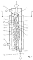
- FIG. 1 the separator according to the invention is shown in longitudinal section for a first embodiment, which has a hollow cylindrical stirnitig open filter element 4 with jacket perforations in the micron range in the interior 10 of a hollow cylindrical front side, in the interior 7 in turn a hollow cylindrical core element 2 is added, which on a drive shaft 1 by means of an electric motor, not shown in the clockwise direction 13 is driven.
- Gleitelementhaltem 8 On the outer jacket of the rotatable core element 2, a plurality of Gleitelementhaltem 8 is now housed in a special arrangement, which will be described in more detail below, in each case a sliding element 9, 9a, 9b made of plastic is added to these Gleitelementhaltern 8.
- an inlet 6 for the product to be cleaned is provided in the housing 3, which then flows on the primary side into the interior 7 of the core element 2.
- the product to be cleaned is filtered through the plurality of sliding elements 9 on the one hand through the plurality of openings in the micron range in the filter element 4 as a purified product and flows out of the output 11 for good product.
- the unwanted solids in the product to be cleaned from the inner wall 4 a of the filter element 4 are scraped and crushed, as well as spirally down towards output 5 and drain valve 12 promoted, due to the spiral arrangement of the sliding elements 9 on the shell of the core element. 2
- adjacent sliding elements 9 have a distance 27 from each other, wherein the sliding elements 9 of an imaginary spiral 14, 15 but can overlap circumferentially.
- the concentration of unwanted solids in the interior 10 of the housing 3 decreases from top to bottom, i. from the inlet 6 to the outlet 5 strongly progressive, wherein at the bottom of the housing 3, the highest solids concentration prevails.
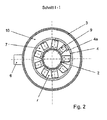
- FIG. 2 is a radial cross section through the separator after FIG. 1 shown along the arrows 1-1.
- FIG. 3 It schematically shows only the core element 2 with the sliding element holders 8 and the sliding elements 9 fastened thereon. It can be seen that two imaginary spirals 14, 15 axially displaced from one another by 25 mm are present on the shell on which the sliding element holders 8 with sliding elements 9 are located. This results in a pitch of 50 mm for each imaginary spiral 14, 15 and an axial offset of about 10 mm for adjacent Gleitelementhalter 8 with sliding elements 9 on one of the spirals 14, 15th
- Gleitelementhalter 8 Per revolution of the imaginary spirals 14, 15 8 piece Gleitelementhalter 8 are each arranged with a sliding element 9 evenly distributed over the circumference, so that there is a circumferential angular distance of 45 ° between the Gleitelementhaltem 8 and sliding elements 9.
- the Gleitelementhalter 8 and sliding elements 9 on the first imaginary spiral 14 are also offset to the Gleitelementhaltem 8 and sliding elements 9 of the second imaginary spiral 15 by a circumferential angular distance of 22.5 °.
- FIG. 4 shows the development of the cylinder of the core element 2 of FIG. 3 from which, in turn, the pitches of 50 mm for the two imaginary spirals 14, 15 emerge, but also that the width axis 16 of each Gleitelementhalters 8 and the longitudinal axes 17 of each slider 9 are rotated by 45 ° to the longitudinal axis of the core element 2.
- the contact surface 18 of the sliding elements 9, which run on the inner circumferential surface of the filter 4 also chamfered by 45 ° to the longitudinal axes 17 of the sliding element 9, so that the entire end face 26 can contact the filter 4.
- FIG. 5 schematically represents the angular deflection of the Gleitelementhalters 8 and the sliding member 9 from the tangential 19 of the core member 2 of 10 ° in the expanded state of the filter element 4.
- Clearance angle 22 is the angle between the tangential 20 of the filter element 4 and the radially outer longitudinal surface 24 of the slider 9.
- the wedge angle 29 is the angle of the wedge, the forms the cutting or scraping edge 18 of the sliding element 9, which lies here between the radially outer longitudinal surface 24 of the sliding element 9 and the front end surface 26 of the sliding element 9.
- the rake angle 23 of the slider 9 is defined as 90 ° (i.e., the angle of the normal 21 to the tangent 20) minus the angle of intersection 28, which is positive at “cutting” and negative at "cockroaching".
- a sliding member 9b which has a wedge angle 29 of 90 °, so that the rake angle or Abtragewinkel 23 of the sliding element 9 is negative and is at minus 45 °, if the clearance angle 22 is for example 45 °, so that the intersection angle 28th at 135 °.
- the clearance angle 22 is in FIG. 7 about 25 °, the wedge angle 29 about 30 °, therefore, the cutting angle 28 is here about 55 °, as is the positive chip / Abtragewinkel 23 at + 35 °. So here is a cutting sliding element 9a.
- FIGS. 6 and 7 with respect to the angular relationships of the sliding elements 8 apply to both embodiments according to the Figures 1-5 and FIGS. 8 and 9, which will be described below.
- FIGS. 8 and 9 the separator according to the invention is the Figures 1-7 shown in an alternative embodiment, wherein the angular arrangements of the sliding element 9 of the FIGS. 6 and 7 but identical in both embodiments.
- the sliding element holders 8 are made of two mutually parallel, a small mutual distance of e.g. 2 cm slipper holder spirals 34 e.g. formed of metal wire, which are applied to V-shaped brackets 30, which in turn are welded onto the outer jacket of the core element 2.
- the Gleitelementhalter spirals 34 are continuously interrupted or just interrupted by short sections.
- the slide element holders 8 include slide element holder hooks 31 spaced apart from e.g. 2 cm are welded to the upper Gleitelementhalter-spiral 34 on the outer surface of the core member 2 and in which the sliding elements 9 can be hung or clipped with eyelets 32.
- the Gleitelementhalter spirals 34 are welded to the free ends of the legs of the V-shaped bracket 30, which in turn are welded to the connection point of the two legs on the outer surface of the core element 2.
- the sliding elements 9 are further arranged along at least one imaginary helical line 14 lying one behind the other on the shell of the core element 2 and have between them a distance 27 in the axial and / or circumferential direction of the core element 2, through which liquid to be purified can flow.
- the sliding elements 9 are formed on one or more sliding element spiral bands 33 in one piece or cohesively.
- a 360 ° sliding element spiral band 33 is provided per approx. 20 cm axial length of the core element 2.
- the sliding element spiral bands 33 of the sliding elements 9 are then inserted between the two sliding element holder spirals 34, the upper receiving lugs 32 of the sliding element holder spirals 34 are positively hooked into the sliding element holder hooks 31, and the sliding element spiral tapes 33 are frictionally pressed down, so that the entire sliding element spiral bands 33 are elastically clamped and fixed in position between the two sliding element holder spirals 34.
- the hooks 31 on the core element 2 and eyelets 32 in the holder 8 can of course also be interchanged with each other, so that the hooks 31 can be provided on the holder 8 and the eyelets 32 on the core element 2.
- Advantages of this second embodiment are that only a few slider spiral bands 33 are present, which are simple and quick to assemble and disassemble by simply clamping and clipping into the Gleitelementhalter 8.
- the abutment surfaces between the slider spiral tapes 33 and the slider holder spirals 34 are reduced, and further, the slider spiral tapes 33 are elastically resilient on the slider holder spirals 34, so that cleaning can be performed less frequently, easily, and quickly.
Abstract
Description
Die Erfindung betrifft einen Separator zur Abtrennung von Feststoffen aus insbesondere hochviskosen Flüssigkeiten, nach dem Oberbegriff des Patentanspruches 1 oder 3.The invention relates to a separator for the separation of solids from in particular highly viscous liquids, according to the preamble of
Die Patentschrift
Mit der
Die Vorrichtung der
Die
Aufgabe der vorliegenden Erfindung ist es, ausgehend vom zuvor genannten Stand der Technik, einen Filter bzw. Separator derart weiterzubilden, dass der Trennwirkungsgrad, d.h. das Verhältnis der Masse des gereinigten Endproduktes zur Masse des verunreinigten Ausgangsproduktes wesentlich erhöht wird. Zudem soll diese Erhöhung des Trennwirkungsgrades in kürzerer Trennzeit erfolgen, sowie die Trennvorrichtung nicht kostenintensiver als beim Stand der Technik sein.It is an object of the present invention, starting from the aforementioned prior art, to develop a filter or separator in such a way that the separation efficiency, i. the ratio of the mass of the purified end product to the mass of the contaminated starting material is substantially increased. In addition, this increase in the separation efficiency should take place in a shorter separation time, and the separation device should not be more costly than in the prior art.
Zur Lösung dieser Aufgaben dienen die Merkmale des unabhängigen Patentanspruches 1 oder 3.To solve these problems serve the features of
Vorteilhafte Weiterbildungen sind Gegenstand der abhängigen Ansprüche.Advantageous developments are the subject of the dependent claims.
Die vorliegende Erfindung unterscheidet sich zum einen von der
Vorteil hierbei ist, dass durch das Schneiden der Gleitelemente der vorliegenden Erfindung größere Schmutzpartikel zerkleinert und schnellst möglich in Richtung Auslass transportiert werden. Damit wird der Trennwirkungsgrad erhöht und die Trennzeit erniedrigt, ohne die Kosten für den Separator wesentlich zu erhöhen.Advantage here is that by cutting the sliding elements of the present invention larger particles of dirt crushed and transported as soon as possible towards the outlet. Thus, the separation efficiency is increased and the separation time is lowered, without significantly increasing the costs for the separator.
Die vorliegende Erfindung unterscheidet sich weiterhin von der
Die Gleitelemente sind also entlang der Längsachse des Mantels des Kernelementes auf mindestens einer gedachten Schraubenlinie hintereinander liegend angeordnet und weisen zwischen sich einen Abstand in axialer und/oder umfänglicher Richtung des Kernelementes auf, durch welchen zu reinigende Flüssigkeit strömen kann. Insbesondere überlappen sich benachbarte Gleitelemente aber in umfänglicher Richtung des Kernelementes.The sliding elements are thus arranged one behind the other along the longitudinal axis of the shell of the core element on at least one imaginary helical line and have between them a distance in the axial and / or circumferential direction of the core element through which liquid to be purified can flow. In particular, however, adjacent sliding elements overlap in the circumferential direction of the core element.
Vorteil hierbei ist, dass damit eine geringe spiralförmige Strömung der zu reinigenden Flüssigkeit in Richtung auf den Auslass hin erzeugt wird und die von der Filterinnernwand durch die Gleitelemente abgetragenen Schmutzteilchen recht schnell von Gleitelement zu Gleitelement in Richtung auf den Auslass transportiert werden und nur geringe Mengen davon wieder zurück in die zu reinigende Flüssigkeit und wieder auf den Filter gelangen. Durch den Abstand zwischen den Gleitelementen strömt die zu reinigende Flüssigkeit hauptsächlich in Richtung Filter und nur in geringem Maße spiralförmig in Richtung Auslass, so dass immer zunächst am Filter eine Trennung der Feststoffe von der Flüssigkeit erfolgt, bevor diese Feststoffe mit der geringen spiralförmigen Strömung und je nach Einbaulage ggfs. auch auf Grund der Gravitation insbesondere von Gleitelement zum nächsten axial beabstandeten Gleitelement auf der gleichen und/oder der benachbarten Spirale in Richtung Auslass befördert werden. Damit wird eine stark progressive Konzentrationserhöhung der Feststoffe in der Flüssigkeit vom Einlass zum Auslass erzeugt, so dass die durch die Gleitelemente vom Filter abgetragenen Feststoffe nicht mehrmals über die Filterhöhe gefiltert werden müssen, sondern im Idealfall nur ein einziges mal. Dies ist der Grund für die Erhöhung des Trennwirkungsgrades durch die spiralförmige Anordnung der voneinander geringfügig beanstandeten Gleitelemente.The advantage here is that thus a small spiral flow of the liquid to be cleaned is generated in the direction of the outlet and the dirt removed by the filter inner wall by the sliding dirt particles are transported quite quickly from sliding element to sliding element in the direction of the outlet and only small amounts thereof back into the liquid to be cleaned and back to the filter. Due to the distance between the sliding elements, the liquid to be purified flows mainly in the direction of the filter and only slightly helical towards the outlet, so that always first on the filter, a separation of the solids from the liquid before these solids with the low spiral flow and depending Depending on the installation position, it may also be conveyed in the direction of the outlet on the same and / or the adjacent spiral due to gravity, in particular from the sliding element to the next axially spaced sliding element. This produces a highly progressive increase in the concentration of solids in the liquid from the inlet to the outlet, so that the solids removed from the filter by the sliding elements need not be filtered several times over the filter height, but ideally only once. This is the reason for the increase in the separation efficiency by the helical arrangement of the slightly offended sliding elements.
Hierdurch ist es bei der Verarbeitung eines zu filternden Produktesmöglich, Schmutzfracht derart herauszufiltern, dass nur noch z.B. unter 0,1% der Menge des ursprünglichen Gutprodukts im Abtrennprodukt enthalten ist, was mit der bisherigen Technik bisher nicht möglich war. Wichtig hierbei ist, dass in dem Abtrennprodukt kaum Gutprodukt drin ist, so dass eine ausgezeichnete Unterscheidung zwischen dem Gutprodukt und dem Abtrennprodukt erfolgt, ohne dass die Gefahr besteht, dass das allzuviel Gutprodukt mit dem Abtrennprodukt mit ausgeschieden wird. Kern der Erfindung liegt in der besonderen Abrelnigungstechnik, bei der auf einen zylindrischen oder auch konischen Kern einer Abreinigungsvorrichtung eine mehrgängige Schraubenwendel angeordnet ist und im Bereich dieser Schraubenwendel senkrecht hierzu stehende und im Abstand voneinander befindliche Gleitelemente aus Kunststoff angeordnet sind, die sich in Biegerichtung elastomer federnd an die Innenwand des Filters anlegen und in Schubrichtung über die Filterinnenwandung streichen, um so eine Separierung des Gutproduktes vom Schlechtprodukt zu ermöglichen. Es geschieht so eine Reinigung der Filterinnenwand durch Abschneiden der Partikel in/auf den Löchern und Weitertransport in Richtung Abfluss. Während des Transports Richtung Abfluss findet das Separieren statt, durch das immer wieder Gutprodukt durch die Löcher Richtung Sekundärseite gelangt und so das Produkt auf der Primärseite immer weiter eindickt.This makes it possible during the processing of a product to be filtered to filter out dirt load such that only eg less than 0.1% of the amount of the original good product contained in the separation product, which is the previous Technology was not possible until now. It is important that in the separation product hardly good product is in it, so that an excellent distinction between the good product and the separation product takes place without the risk that the excess of good product with the separation product is excreted with. The essence of the invention lies in the special Abrelnigungstechnik in which a multi-start helical coil is arranged on a cylindrical or conical core of a cleaning device and are arranged in the region of this helix perpendicular thereto and spaced apart sliding plastic, which are elastically resilient in the bending direction Put on the inner wall of the filter and stroke in the thrust direction on the filter inner wall, so as to allow a separation of the good product from the bad product. It is done so a cleaning of the filter inner wall by cutting the particles in / on the holes and further transport towards the drain. Separation takes place during the transport to the outflow, through which good products pass through the holes in the direction of the secondary side again and again, thus thickening the product on the primary side.
Nachdem diese Gleitelemente schraubenförmig angeordnet sind, machen diese durch Drehung des Kernes auch eine entsprechende schraubenförmig, z. B. nach unten gerichtete Abreinigungsbewegung des Schlechtproduktes in Richtung auf den Boden des Filters, so dass das Schlechtprodukt von dem Boden leicht abgelassen werden kann und vom Gutprodukt dadurch separiert wird.After these sliders are arranged helically, make this by rotation of the core and a corresponding helical, z. B. downward cleaning movement of the bad product towards the bottom of the filter, so that the bad product can be easily drained from the ground and is separated from the good product thereby.
Durch die schraubenförmig gerichtete Abwärtsbewegung der Gleitelemente besteht der weitere Vorteil, dass das Schlechtprodukt im Bereich des Bodensumpfes sozusagen komprimiert wird und in komprimierter Form auch von dem bedarfsweise zu öffnenden Auslass entnommen werden kann.Due to the helically directed downward movement of the sliding elements, there is the further advantage that the poor product in the region of the bottom sump is, so to speak, compressed and can also be removed in compressed form from the outlet, which can be opened as required.
- 1. Separieren von festen Bestandteilen aus niedrig bis hochviskosen Produkten.1. Separation of solid components from low to high viscosity products.
- 2. Produktmenge zwischen Filterinnenwand und Kernelement muss eine gewisse Größe aufweisen, dass sich das Produkt auf dem Transport durch die Kunststoffsegmente (Gleitelemente) nach unten eindickt.2. The amount of product between the filter inner wall and the core element must be of a certain size such that the product thickens downwards during transport through the plastic segments (sliding elements).
- 3. Das Gutprodukt strömt auf die Sekundärseite des Filterelements, die Partikel größer als die Lochgröße des Filterelements werden von den Löchern weggeschoben oder abgeschnitten.3. The good product flows on the secondary side of the filter element, the particles larger than the hole size of the filter element are pushed away from the holes or cut off.
- 4. Die Partikel größer als Lochgröße werden nach unten transportiert und nach variabel zu bestimmenden Eindickungsgrad aus dem Auslass ausgeschleust.4. The particles larger than the hole size are transported downwards and discharged out of the outlet according to the degree of thickening to be determined.
- 5. Rein durch die Vorspannung der Kunststoffsegmente wird der Anpressdruck der Gleitelemente auf die Filterinnenwand erzeugt.Während dem Eindicken drückt die Schmutzfracht / Abgeschabtes Produkt /Partikel größer der 15 Lochung durch die Drehbewegung gegen den Kunststoff vom Spiralschaber und drückt diesen noch stärker an die Filterwandung. Desto mehr Schmutzfracht desto höher der Druck auf die Gleitelemente/ Spiralschaber, Man könnte also sagen, dass die Vorspannung vom Kunststoff nur für den beginn der Filterung nötig ist und nach dem Start die Gleitelemente / 20 Spiralschaber durch Ihre Form/ Schräge vom Produkt und der Schmutzfracht an die Filterwandung gedrückt werden.5. Due to the prestressing of the plastic segments, the contact pressure of the sliding elements is produced on the filter inner wall. During thickening, the dirt load / scraped product / particle presses larger than the 15 holes by the rotary movement against the plastic from the spiral scraper and presses it even more strongly against the filter wall. The more dirt load the higher the pressure on the sliding elements / spiral scrapers. So one could say that the pre-tensioning of the plastic is only necessary for the beginning of the filtration and after the start the sliding elements / 20 spiral scrapers by their shape / slope of the product and the dirt load pressed against the filter wall.
- 1. Produkt strömt über den Produkteingang ins Gehäuse des Separators.1. Product flows into the housing of the separator via the product inlet.
- 2. Produkt strömt, am Kernelement vorbei, Richtung Filterelement.2. Product flows, past the core element, towards the filter element.
- 3. Produkt kleiner 50 µm strömt durch die Laserlöcher von der Primärseite zur Sekundärseite.3. Product smaller than 50 μm flows through the laser holes from the primary side to the secondary side.
- 4. Partikel größer 50 µm bleiben vor oder in den Laserlöchern liegen.4. Particles larger than 50 μm remain in front of or in the laser holes.
- 5. Von der Sekundärseite des Filterelements fließt das gefilterte Produkt am Produktausgang aus dem Gehäuse heraus.5. From the secondary side of the filter element, the filtered product flows out of the housing at the product outlet.
- 6. Durch die Drehbewegung der spiralförmig angeordneten Gleitelemente werden die Partikel vor den Laserlöchern von den Gleitelementen auf dem Filterelement weggeschoben.6. Due to the rotational movement of the helically arranged sliding elements, the particles are pushed away from the laser elements on the sliding elements on the filter element.
- 7. Die teils in den Laserlöchern steckenden Partikel werden von den Gleitelementen abgeschnitten.7. The particles partly stuck in the laser holes are cut off by the sliding elements.
- 8. Es können nur Partikel, Fremdkörper oder ähnliches aus dem Gutprodukt separiert werden, die eine gewisse Eigenfestigkeit besitzen.8. Only particles, foreign bodies or the like can be separated from the good product, which have a certain inherent strength.
- 9. Hat ein Fremdkörper eine zu geringe Eigenfestigkeit, wird dieser entweder durch die Löcher gedrückt, oder vom Gleitelement abgeschnitten, sollte dieser noch ein Stück aus dem Loch vorstehen.9. If a foreign body has a too low intrinsic strength, this is either pushed through the holes, or cut off from the sliding element, this should still protrude a bit out of the hole.
- 10. Durch die Anordnung der Gleitelemente werden die Partikel auf der Primärseite von den Löchern weggeschoben oder die teilweise in den Löchern steckenden Partikel abgeschnitten und Richtung Abschlammventil transportiert.10. The arrangement of the sliding elements, the particles are pushed away from the holes on the primary side or cut off the partially stuck in the holes particles and transported direction Abschlammventil.
- 11. Durch den Transport Richtung Abschlammventil dickt das Produkt immer mehr ein, da das Gutprodukt durch die Löcher Richtung Sekundärseite gelangt und die Partikel größer 50 µm auf der Primärseite gehalten werden.11. Due to the transport towards the blow-down valve, the product thickens more and more, as the good product passes through the holes in the direction of the secondary side and the particles larger than 50 μm are held on the primary side.
- 12. Nun beginnt die Separierung des Gutprodukts und den auszuschleusenden Partikeln.12. Now the separation of the good product and the particles to be rejected begins.
- 13. Durch das immer weitere Eindicken des verschmutzten Produkts vor dem ausschleusen ist ein separieren von Partikeln möglich mit einer Restmenge von unter 10% Gutprodukt im ausgeschleusten Material.13. Due to the further thickening of the soiled product prior to discharge, a separation of particles is possible with a residual amount of less than 10% good product in the discharged material.
- 14. Das Abschlammen funktioniert durch den Differenzdruck P1 Primär zu PO Atmosphäre.14. Sludge works by differential pressure P1 Primary to PO Atmosphere.
- 15. Die Abschlammzeiten und Mengen sind rein von der Kontamination des zu filternden Produkts abhängig.15. The sludge times and quantities are purely dependent on the contamination of the product to be filtered.
- 16. Je niedriger der Differenzdruck zwischen Primärseite und Sekundärseite, desto besser das Ergebnis der Separation.16. The lower the differential pressure between the primary side and the secondary side, the better the result of the separation.
Die Partikel, die nicht ganz durch die Löcher gehen, werden von den Gleitelementen in Form von Kunststoffsegmenten abgeschnitten. Die Gleitelemente legen sich an der Filterinnenwand über eine definierte Vorspannung, die durch die Anordnung der Gleitelementhalterung auf dem Kernelement erzeugt wird, durch die Eigenspannung des Gleitelernentmatehals an.The particles that do not go completely through the holes are cut off by the sliding elements in the form of plastic segments. The sliding elements lie against the filter inner wall via a defined preload, which is generated by the arrangement of Gleitelementhalterung on the core element, by the residual stress of the Gleitelernentmatehals.
Die
Die Gleitelemente mit Freiwinkel ca. 20°, Keilwinkel ca.90°der vorliegenden Erfindung schneiden nach einer gewissen Betriebszeit, da sie sich selbst nachschärfen und sich der negative Spanwinkel mit dem Nachschärfen ändert, also positiv wird.The sliding elements with clearance angle about 20 °, wedge angle about 90 ° of the present invention cut after a certain period of operation, since they re-sharpen themselves and the negative rake angle changes with the resharpening, so it becomes positive.
Die der
Die Anordnung des erfindungsgemäßen Gleitelementes ist gesehen im 3D Bild in 2 Dimensionen verschieden.The arrangement of the sliding element according to the invention is seen in the 3D image in 2 dimensions different.
Das erfindungsgemäße Gleitelement ist eckig.The sliding element according to the invention is angular.
Der Spiralschaber ist eine ca. 180° Ronde / Halbkreis mit Haltelaschen und Schlitze dass sich der Kunststoff besser an die Filterwandung anlegt.The spiral scraper is an approximately 180 ° Ronde / semicircle with retaining tabs and slots that the plastic rests better on the filter wall.
Die
Die vorliegende Erfindung arbeitet nicht mit einem relativ kleinvolumigen Ringspalt, sondern benötigt einen relativ großvolumigen Ringraum.The present invention does not work with a relatively small volume annulus but requires a relatively large volume annulus.
Bei der Konstruktion der vorliegenden Erfindung wird eine Drehrichtung festgelegt und dadurch ergeben sich die Positionen und Ausrichtungen der Kunststoffsegmente, was bedeutet, dass ein Kernelement für Links oder Rechtslauf ausgelegt ist. Während der Produktion dreht das Kernelement also immer nur in eine Richtung.In the construction of the present invention, a rotational direction is set and thereby the positions and orientations of the plastic segments result, which means that a core element is designed for left or right-handed rotation. During production, the core element always turns in one direction only.
Die Drehrichtung der vorliegenden Erfindung ist nicht relevant, da es auch spiegelverdreht (auf dem Kopf stehend) eingebaut werden kann.The direction of rotation of the present invention is not relevant because it can also be installed mirror-inverted (upside down).
Die vorliegende Erfindung dickt das Produkt ein und separiert die Partikel größer der Lochgröße des Filters aus.The present invention thickens the product and separates the particles larger than the hole size of the filter.
Die
Die erfindungsgemäßen Gleitelemente haben eine Dicke von bevorzugt t=1 mm, Die Schaber der
Die erfindungsgemäßen Gleitelemente sind im Kernelement fest geklemmt oder dort in einem Schnellspannsystem eingeklipst.The sliding elements according to the invention are firmly clamped in the core element or clipped there in a quick release system.
Die Gleitelemente der
Die vorliegende Erfindung nutzt keine Strömungsgeschwindigkeiten.The present invention does not use flow rates.
Das die Gleitelemente tragende Kernelement hat bevorzugt einen Außendurchmesser von 80 mm und eine axiale Länge von ca. 550 mm, kann aber auch andere Dimensionen haben.The core element carrying the sliding elements preferably has an outer diameter of 80 mm and an axial length of about 550 mm, but may also have other dimensions.
Die Vielzahl der Gleitelementhalterungen und darauf angebrachten Gleitelementen sind auch dem Kernelement in Form eines 2-gängigen Gewindes mit einer Steigung von je 50 mm verteilt. Die Position der Gleitelementhalterungen zur Achse des Kernelements liegt bevorzugt bei ca. 45°. Jedes Gleitelement ist dabei um 10 mm in Richtung der Längsachse des Kernelements zum benachbarten Gleitelement versetzt. Der Gleitelementhalter Ist auf dem Kernelement so aufgebracht (insbesondere aufgeschweißt), dass der Gleitelementhalter zur Tangente des Außenmantels des Kernelements etwa 10° einnimmt.The plurality of Gleitelementhalterungen and mounted thereon sliding elements are also distributed to the core element in the form of a 2-threaded thread with a pitch of 50 mm. The position of the Gleitelementhalterungen to the axis of the core member is preferably about 45 °. Each sliding element is offset by 10 mm in the direction of the longitudinal axis of the core element to the adjacent sliding element. The Gleitelementhalter Is applied (in particular welded) on the core element, that the Gleitelementhalter to the tangent of the outer shell of the core element occupies about 10 °.
Es wird bevorzugt, dass es sich um ein 2-gängiges Gewinde handelt. Dabei sind die Gleitelementhalterungen 45° zur Mittelachse gedreht und sind 40mm lang. Ein 1,2,3,4......gängiges Gewinde würde genauso funktionieren, so dass sämtliche ein- und mehrfachen Gewindegänge beansprucht werden. Bevorzugt ist aber ein 2-gängiges Gewinde, da bei dieser Anordnung ca. 50 Stück Gleitelemente auf einem Gang und somit bei zwei Gängen 100 Stück Gleitelemente verteilt werden können.It is preferred that it is a 2-threaded thread. The Gleitelementhalterungen are rotated 45 ° to the central axis and are 40mm long. A 1,2,3,4 ...... common thread would work the same, so that all single and multiple threads are claimed. Preferably, however, a 2-threaded thread, since in this arrangement about 50 pieces of sliding elements in a corridor and thus at two courses 100 pieces of sliding elements can be distributed.
Grundsätzlich ist der Versatz nötig um die abgeschnittenen Partikel, die sich auf den Gleitelementen ansammeln von einem Gleitelement aufs andere zu leiten. Die Gleitelemente sind also überlappend auf der Steigung angeordnet. Ist der Versatz 10 mm und z.B. 8 Gleitelemente auf eine Umdrehung, so wäre die Steigung 80 mm. Ist der Versatz 6 mm und 8 Gleitelemente auf eine Umdrehung, wäre die Steigung 48 mm. Eine Verzerrung von 48 mm auf die bevorzugten 50 mm Steigung ergibt sich durch die Umrechnung von Durchmesser und den Maßstab. Es ist aber unerheblich, welche Steigung tatsächlich eingesetzt wird. Der Versatz ist also die Steigung pro Gleitelement.Basically, the offset is necessary to pass the cut particles that accumulate on the sliding elements from one slider to another. The sliding elements are thus arranged overlapping on the slope. If the offset is 10 mm and e.g. 8 sliding elements in one turn, the pitch would be 80 mm. If the offset is 6 mm and 8 sliding elements in one turn, the pitch would be 48 mm. A distortion of 48 mm on the preferred 50 mm pitch results from the conversion of diameter and scale. It does not matter which slope is actually used. The offset is thus the pitch per slider.
Das Filterelement kann zylindrisch aber auch kegelig sein.The filter element may be cylindrical or conical.
Die Lochgröße des Filterelementes beträgt zwischen 30 und 400 µm, wobei das Lochbild und die Gestalt der Durchbrüche keine Rolle spielt.The hole size of the filter element is between 30 and 400 microns, the hole pattern and the shape of the apertures does not matter.
Die Gleitelemente haben eine elastisch federnde Vorspannung im in den Filter eingebauten Zustand.The sliding elements have an elastically resilient bias in the installed state in the filter.
Die Gleitelemente sind am Kernelement angeschraubt oder dort geklemmt oder eingeklipst.The sliding elements are screwed to the core element or clamped or clipped there.
Es ist ein kontinuierlicher Betrieb oder ein Batchbetrieb mit dem erfindungsgemäßen Separator möglich, d.h. entweder ist das Ablassventil stets offen oder es wird nur nach einer längeren Betriebszeit zum vollständigen Entleeren des Separators geöffnet um anschließend geschlossen zu werden und den Separator neu zu füllen. Der erfindungsgemäße Separator kann in jeder beliebigen Lage betrieben werden, stehend mit Einlass oben und Ablass unten oder umgekehrt oder aber auch liegend oder gar schräg mit seiner Längsachse im Winkel zur Horizontalen.It is a continuous operation or a batch operation with the separator according to the invention possible, ie either the drain valve is always open or it is opened only after a longer period of operation for complete emptying of the separator to be subsequently closed and to refill the separator. The separator according to the invention can be operated in any position, standing with inlet above and outlet below or vice versa or even lying or even obliquely with its longitudinal axis at an angle to the horizontal.
Wichtig ist aber, dass das zu bearbeitende Produkt pumpfähig sein muss, wobei sich der der Anpressdruck der Pumpe durch die Art, Größe und Menge der Verschmutzung sowie der Viskosität des zu bearbeitenden Produktes ergibt.It is important, however, that the product to be processed must be pumpable, whereby the contact pressure of the pump is determined by the type, size and amount of contamination as well as the viscosity of the product to be processed.
Im Folgenden wird die Erfindung anhand zweier Ausführungsformen beispielhaft näher erläutert, wobei die Figuren zeigen:
-
Figur 1 : Ein axialer Längsschnitt durch die Längsachse des erfindungsgemäßen Separators nach einer ersten Ausführungsform; -
Figur 2 : Ein radialer Querschnitt senkrecht auf die Längsachse des erfindungsgemäßen Separators nachFigur 1 ; -
Figur 3 : Schematisierte Längsansicht auf das zylindrische Kernelement derFigur 1 und2 ; -
Figur 4 : Abwicklung des zylindrischen Kernelements derFigur 3 ; -
Figur 5 : Schematisierte Draufsicht auf das zylindrische Kernelement derFigur 3 mit Einzelheit des Einbauzustandes des Gleitelementes; -
Figur 6 : Gleitelement mit Keilwinkel von 90° und negativem Spanwinkel/Abhebewinkel für die erste Ausführungsform nach denFiguren 1-5 und für die zweite Ausführungsform nachden Figuren 8 und 9; -
Figur 7 : Gleitelement mit Keilwinkel von 30° und positivem Spanwinkel/Abhebewinkel für die erste Ausführungsform nach denFiguren 1-5 und für die zweite Ausführungsform nachden Figuren 8 und 9; - Figur 8: Ein axialer Längsschnitt durch die Längsachse des erfindungsgemäßen Separators nach einer ersten Ausführungsform:
- Figur 9: Ein radialer Querschnitt senkrecht auf die Längsachse des erfindungsgemäßen
Separators nach Figur 8.
-
FIG. 1 : An axial longitudinal section through the longitudinal axis of the separator according to the invention according to a first embodiment; -
FIG. 2 : A radial cross section perpendicular to the longitudinal axis of the separator according to the inventionFIG. 1 ; -
FIG. 3 : Schematized longitudinal view of the cylindrical core element ofFIG. 1 and2 ; -
FIG. 4 : Development of the cylindrical core element ofFIG. 3 ; -
FIG. 5 : Schematized plan view of the cylindrical core element of theFIG. 3 with detail of the installation state of the sliding member; -
FIG. 6 Sliding element with wedge angle of 90 ° and negative rake angle / Abhebewinkel for the first embodiment according to theFigures 1-5 and for the second embodiment of Figures 8 and 9; -
FIG. 7 Sliding element with wedge angle of 30 ° and positive rake angle / Abhebewinkel for the first embodiment of theFigures 1-5 and for the second embodiment of Figures 8 and 9; - FIG. 8: an axial longitudinal section through the longitudinal axis of the separator according to the invention according to a first embodiment:
- FIG. 9: A radial cross section perpendicular to the longitudinal axis of the separator according to the invention according to FIG. 8.
In
Auf dem Außenmantel des drehbaren Kernelements 2 ist nun eine Vielzahl von Gleitelementhaltem 8 in einer speziellen Anordnung aufgenommen, die nachfolgend näher beschrieben wird, wobei auf diesen Gleitelementhaltern 8 jeweils ein Gleitelement 9, 9a, 9b aus Kunststoff aufgenommen ist.On the outer jacket of the
I oberen Bereich ist im Gehäuse 3 ein Eingang 6 für das zu reinigende Produkt vorgesehen, welches dann primärseitig in den Innenraum 7 des Kernelementes 2 fließt. Bei Drehung des Kernelementes 2 wird nun das zu reinigende Produkt durch die Vielzahl der Gleitelemente 9 einerseits durch die Vielzahl von Öffnungen im µm-Bereich im Filterelement 4 als gereinigtes Produkt hindurchgefiltert und fließt aus dem Ausgang 11 für Gutprodukt aus. Andererseits werden die unerwünschten Feststoffe im zu reinigenden Produkt von der Innenwand 4a des Filterelementes 4 abgekratzt und zerkleinert, sowie spiralförmig nach unten in Richtung Ausgang 5 und Ablaufventil 12 gefördert, auf Grund der spiralförmigen Anordnung der Gleitelemente 9 auf dem Mantel des Kernelementes 2.In the upper area, an
Wichtig hierbei ist, dass benachbarte Gleitelemente 9 einen Abstand 27 voneinander aufweisen, wobei die Gleitelemente 9 einer gedachten Spirale 14, 15 sich dabei aber umfänglich überlappen können.It is important that adjacent sliding
Hierdurch nimmt die Konzentration von unerwünschten Feststoffen im Innenraum 10 des Gehäuses 3 von oben nach unten, d.h. vom Einlass 6 zum Auslass 5 stark progressiv zu, wobei am Boden des Gehäuses 3 die höchste Feststoffkonzentration herrscht.As a result, the concentration of unwanted solids in the
In
Pro Umdrehung der gedachten Spiralen 14, 15 sind 8 Stück Gleitelementhalter 8 mit je einem Gleitelement 9 gleichmäßig über den Umfang verteilt angeordnet, so dass sich ein Umfangs-Winkelabstand von 45° zwischen den Gleitelementhaltem 8 bzw. Gleitelementen 9 ergibt.Per revolution of the
Die Gleitelementhalter 8 und Gleitelemente 9 auf der ersten gedachten Spirale 14 sind zu den Gleitelementhaltem 8 und Gleitelementen 9 der zweiten gedachten Spirale 15 zudem um einen Umfangs-Winkelabstand von 22,5° versetzt.The
Im in das Filterelement 4 eingebauten Betriebszustand (siehe
Nach
Der Spanwinkel bzw. Abtragewinkel 23 des Gleitelements 9 ist dabei definiert als 90° (d.h. Winkel der Normalen 21 zur Tangentialen 20) minus Schnittwinkel 28, der beim "Schneiden" positiv und beim "Schaben" negativ ist.The
In der Ausführung nach
Der Freiwinkel 22 ist in
Es werden daher bei der vorliegenden Erfindung schneidende Gleitelement 9a mit positiven und Gleitelement 9b mit negativen Spanwinkeln bzw. Abtragewinkeln 23 beansprucht.Therefore, in the present invention, cutting sliding
Die zuvor genannten Merkmale der
In Figuren 8 und 9 ist der erfindungsgemäße Separator der
Im Unterschied zur ersten Ausführungsform der
Die Gleitelementhalter 8 sind aus zwei zueinander parallelen, einen geringen gegenseitigen Abstand von z.B. 2 cm einnehmenden Gleitelementhalter-Spiralen 34 z.B. aus Metalldraht gebildet, welche auf V-förmigen Bügeln 30 aufgebracht sind, die wiederum auf dem Außenmantel des Kernelements 2 aufgeschweißt sind. Die Gleitelementhalter-Spiralen 34 sind dabei durchgehend ununterbrochen oder eben durch kurze Abschnitte unterbrochen. Weiterhin beinhalten die Gleitelementhalter 8 Gleitelementhalter-Haken 31, welche im Abstand von z.B. 2 cm zur oberen Gleitelementhalter-Spirale 34 auf dem Außenmantel des Kernelements 2 aufgeschweißt sind und in welche die Gleitelemente 9 mit Aufnahmeösen 32 eingehängt bzw. eingeklipst werden können. Die Gleitelementhalter-Spiralen 34 sind dabei auf den freien Enden der Schenkel der V-förmigen Bügel 30 aufgeschweißt, die ihrerseits mit dem Verbindungspunkt der beiden Schenkel auf dem Außenmantel des Kernelements 2 aufgeschweißt sind.The sliding
Die Gleitelemente 9 sind weiterhin entlang mindestens einer gedachten Schraubenlinie 14 hintereinander liegend auf dem Mantel des Kernelementes 2 angeordnet sind und weisen zwischen sich einen Abstand 27 in axialer und/oder umfänglicher Richtung des Kernelementes 2 auf, durch welchen zu reinigende Flüssigkeit strömen kann.The sliding
Die Gleitelemente 9 sind auf einem oder mehreren Gleitelement-Spiralbändern 33 einstückig bzw. stoffschlüssig herausgeformt. Bevorzugt ist je ein 360°-Gleitelement-Spiralband 33 auf ca. 20 cm axiale Länge des Kernelements 2 vorgesehen.The sliding
Die Gleitelement-Spiralbänder 33 der Gleitelemente 9 werden dann zwischen die beiden Gleitelementhalter-Spiralen 34 eingeschoben, die oberen Aufnahmeösen 32 der Gleitelementhalter-Spiralen 34 werden in die Gleitelementhalter-Haken 31 formschlüssig eingehängt, und die Gleitelement-Spiralbänder 33 werden reibschlüssig nach unten gedrückt, so dass die gesamten Gleitelement-Spiralbänder 33 elastisch zwischen den beiden Gleitelementhalter-Spiralen 34 eingespannt und lagefixiert sind.The sliding element spiral bands 33 of the sliding
Die Haken 31 auf dem Kernelement 2 und Ösen 32 im Halter 8 können natürlich auch gegeneinander vertauscht sein, so dass die Haken 31 auf dem Halter 8 und die Ösen 32 auf dem Kernelement 2 vorgesehen sein können.The hooks 31 on the
Im in das Filterelement 4 eingebauten Betriebszustand sind dann die Gleitelement-Spiralbänder 33 zwischen den Gleitelementhalter-Spiralen 34 elastisch federnd in Richtung Tangentiale 20 des Filterelementes 4 gebogen.In the built-in
Vorteile dieser zweiten Ausführungsform sind, dass nur noch wenige Gleitelement-Spiralbänder 33 vorhanden sind, die durch einfaches Einspannen und Einklipsen in die Gleitelementhalter 8 einfach und schnell montierbar und demontierbar sind. Zudem sind die Auflageflächen zwischen den Gleitelement-Spiralbändern 33 und den Gleitelementhalter-Spiralen 34 verringert und weiter liegen die Gleitelement-Spiralbänder 33 auf den Gleitelementhalter-Spiralen 34 elastisch federnd auf, so dass eine Reinigung seltener, einfacher und schneller durchgeführt werden kann.Advantages of this second embodiment are that only a few slider spiral bands 33 are present, which are simple and quick to assemble and disassemble by simply clamping and clipping into the
- 1.1.
- Antriebswelledrive shaft
- 2.Second
- Kernelementcore element
- 3.Third
- Gehäusecasing
- 4.4th
- Filterelement mit µm-Mantellochung; 4a FilterinnenwandFilter element with μm jacket perforation; 4a filter inner wall
- 5.5th
- Ausgang SchlechtproduktOutput bad product
- 6.6th
- Eingang zu reinigendes ProduktInput to be cleaned product
- 7.7th
- Primärseiteprimary
- 8.8th.
- Gleitelementhalter für 9Sliding element holder for 9
- 9.9th
- Gleitelement; schneidend 9a; schabend 9bSlide; cutting 9a; heck 9b
- 10.10th
- Sekundärseitesecondary side
- 11.11th
- Ausgang GutproduktOutput good product
- 12.12th
- Ventil (Auf/Zu) in 5Valve (open / close) in 5
- 13.13th
- Drehrichtung von 2Direction of rotation of 2
- 14,14
- gedachte Spiraleimaginary spiral
- 15.15th
- gedachte Spiraleimaginary spiral
- 16.16th
- Breitenachse von 8Width axis of 8
- 17.17th
- Längsachse von 9Longitudinal axis of 9
- 18.18th
- Kontaktkante von 9 auf 4aContact edge from 9 to 4a
- 19.19th
- Tangentiale von 2Tangentials of 2
- 20.20th
- Tangentiale von 4aTangentials of 4a
- 21.21st
- Normale auf 20Normal to 20
- 22.22nd
- Schnittwinkelcutting angle
- 23.23rd
- Spanwinkel bzw. AbtragewinkelRake angle or removal angle
- 24.24th
- radial äußere Längsfläche von 9radially outer longitudinal surface of 9
- 25.25th
- radial innere Längsfläche von 9radially inner longitudinal surface of 9
- 26.26th
-
vordere Stirnfläche 26 von 9
front face 26 of FIG. 9 - 27.27th
- Abstand zwischen 9Distance between 9
- 28.28th
- Schnittwinkelcutting angle
- 29.29th
- Keilwinkelwedge angle
- 30.30th
- V-förmiger BügelV-shaped bracket
- 31.31st
- Gleitelementhalter-HakenSlider retainer hook
- 32.32nd
- AufnahmeösenAufnahmeösen
- 33.33rd
- Gleitelement-Spiralband 34. zwei Gleitelementhalter-SpiralenSlide-spiral belt 34. two Gleitelementhalter spirals
Claims (14)
Applications Claiming Priority (1)
| Application Number | Priority Date | Filing Date | Title |
|---|---|---|---|
| DE102010048028A DE102010048028A1 (en) | 2010-10-09 | 2010-10-09 | Separator for the separation of solids from especially high-viscosity liquids |
Publications (1)
| Publication Number | Publication Date |
|---|---|
| EP2438973A1 true EP2438973A1 (en) | 2012-04-11 |
Family
ID=45023477
Family Applications (1)
| Application Number | Title | Priority Date | Filing Date |
|---|---|---|---|
| EP11008091A Withdrawn EP2438973A1 (en) | 2010-10-09 | 2011-10-06 | Separator for separating solids from liquids, particularly high viscosity liquids |
Country Status (2)
| Country | Link |
|---|---|
| EP (1) | EP2438973A1 (en) |
| DE (2) | DE102010048028A1 (en) |
Cited By (2)
| Publication number | Priority date | Publication date | Assignee | Title |
|---|---|---|---|---|
| CN105829057A (en) * | 2013-10-04 | 2016-08-03 | 奥地利埃瑞玛再生工程机械设备有限公司 | Filter device |
| WO2021019494A1 (en) * | 2019-08-01 | 2021-02-04 | Zvi Livni | Self cleaning filtering apparatus for plate heat exchangers |
Families Citing this family (2)
| Publication number | Priority date | Publication date | Assignee | Title |
|---|---|---|---|---|
| AT514439B1 (en) * | 2013-10-04 | 2015-01-15 | Erema | filter means |
| CN107670362A (en) * | 2017-10-20 | 2018-02-09 | 新乡市华航航空液压设备有限公司 | A kind of filter core of high contamination capacity structure |
Citations (11)
| Publication number | Priority date | Publication date | Assignee | Title |
|---|---|---|---|---|
| DE342018C (en) | 1918-08-02 | 1921-10-26 | Plauson S Forschungsinstitut G | Continuously working filter press |
| US2553567A (en) * | 1945-12-05 | 1951-05-22 | Joseph F Fette | Filter |
| US3762563A (en) * | 1971-02-23 | 1973-10-02 | P Petersen | Cylindrical rotary strainer |
| EP0312354A2 (en) * | 1987-10-16 | 1989-04-19 | Cellier Corporation | Slurry filter |
| DE3809372A1 (en) | 1988-03-19 | 1989-09-28 | Kloeckner Humboldt Deutz Ag | Filter |
| DE3927707A1 (en) | 1988-08-25 | 1990-03-01 | Ciba Geigy Ag | Auxiliary scraper following cake cutter in centrifuge drum - held in resilient contact with the residual layer |
| JPH10272309A (en) * | 1997-03-31 | 1998-10-13 | Muramoto Kensetsu Kk | Wastewater treatment apparatus, and filtration apparatus therefor |
| DE19852119C1 (en) | 1998-11-12 | 2000-07-27 | Martin Systems Ag | Device for separating dirty water |
| WO2005098341A1 (en) * | 2004-04-05 | 2005-10-20 | Heco Filtration A/S | A method and filter unit for filtering in heat exchangers |
| AT413497B (en) * | 2004-10-25 | 2006-03-15 | Erema | DEVICE FOR CONTINUOUSLY FILTERING FLOWABLE MASSES CONTAINING SOLID PARTICLES |
| WO2010070112A1 (en) | 2008-12-19 | 2010-06-24 | Hochland Ag | Filter for use in food processing |
-
2010
- 2010-10-09 DE DE102010048028A patent/DE102010048028A1/en not_active Withdrawn
-
2011
- 2011-09-22 DE DE202011105998U patent/DE202011105998U1/en not_active Expired - Lifetime
- 2011-10-06 EP EP11008091A patent/EP2438973A1/en not_active Withdrawn
Patent Citations (12)
| Publication number | Priority date | Publication date | Assignee | Title |
|---|---|---|---|---|
| DE342018C (en) | 1918-08-02 | 1921-10-26 | Plauson S Forschungsinstitut G | Continuously working filter press |
| US2553567A (en) * | 1945-12-05 | 1951-05-22 | Joseph F Fette | Filter |
| US3762563A (en) * | 1971-02-23 | 1973-10-02 | P Petersen | Cylindrical rotary strainer |
| EP0312354A2 (en) * | 1987-10-16 | 1989-04-19 | Cellier Corporation | Slurry filter |
| DE3809372A1 (en) | 1988-03-19 | 1989-09-28 | Kloeckner Humboldt Deutz Ag | Filter |
| DE3927707A1 (en) | 1988-08-25 | 1990-03-01 | Ciba Geigy Ag | Auxiliary scraper following cake cutter in centrifuge drum - held in resilient contact with the residual layer |
| JPH10272309A (en) * | 1997-03-31 | 1998-10-13 | Muramoto Kensetsu Kk | Wastewater treatment apparatus, and filtration apparatus therefor |
| DE19852119C1 (en) | 1998-11-12 | 2000-07-27 | Martin Systems Ag | Device for separating dirty water |
| WO2005098341A1 (en) * | 2004-04-05 | 2005-10-20 | Heco Filtration A/S | A method and filter unit for filtering in heat exchangers |
| AT413497B (en) * | 2004-10-25 | 2006-03-15 | Erema | DEVICE FOR CONTINUOUSLY FILTERING FLOWABLE MASSES CONTAINING SOLID PARTICLES |
| WO2010070112A1 (en) | 2008-12-19 | 2010-06-24 | Hochland Ag | Filter for use in food processing |
| DE102008063972A1 (en) | 2008-12-19 | 2010-07-01 | Hochland Ag | Filter for use in processed cheese production |
Cited By (3)
| Publication number | Priority date | Publication date | Assignee | Title |
|---|---|---|---|---|
| CN105829057A (en) * | 2013-10-04 | 2016-08-03 | 奥地利埃瑞玛再生工程机械设备有限公司 | Filter device |
| WO2021019494A1 (en) * | 2019-08-01 | 2021-02-04 | Zvi Livni | Self cleaning filtering apparatus for plate heat exchangers |
| US20220268537A1 (en) * | 2019-08-01 | 2022-08-25 | Zvi Livni | Self cleaning filtering apparatus for plate heat exchangers |
Also Published As
| Publication number | Publication date |
|---|---|
| DE102010048028A1 (en) | 2012-04-12 |
| DE202011105998U1 (en) | 2011-11-03 |
Similar Documents
| Publication | Publication Date | Title |
|---|---|---|
| DE602005001538T2 (en) | Device for solid / liquid separation | |
| EP2155353B1 (en) | Press screw separator | |
| EP2326493B1 (en) | Screw filter press | |
| EP2375888B1 (en) | Filter for use in food processing | |
| EP0908569A1 (en) | Screening device for sewage in an inlet pipe | |
| EP2438973A1 (en) | Separator for separating solids from liquids, particularly high viscosity liquids | |
| EP2433692A1 (en) | Device for screening and removing material from a liquid flowing in a channel | |
| AT413497B (en) | DEVICE FOR CONTINUOUSLY FILTERING FLOWABLE MASSES CONTAINING SOLID PARTICLES | |
| DE3122131A1 (en) | Means for removing and draining solids from liquids, in particular from channels in sewage-treatment works | |
| EP3150558B1 (en) | Process for cleaning used wash water from a vehicle wash facility and vehicle wash facility | |
| EP1854764A1 (en) | Reactor comprising a stack of filter plates | |
| AT395325B (en) | DEVICE FOR SEPARATING A CELLULOSE-FIBER-MIXED SUSPENSION | |
| EP3579976B1 (en) | Comminuting device | |
| DE102018113135A1 (en) | Device for sewage sludge dewatering | |
| DE2542300A1 (en) | FILTER DEVICE | |
| EP0465840B1 (en) | Filtering device, especially for the separation of coarse particles from a lubricant suspension and use thereof | |
| DE4006970A1 (en) | Inclined rotary sieves immersed in waste water flow - discharge separated solids into upwardly directed feed worm | |
| DE202020102630U1 (en) | Shredding device | |
| EP0736370A2 (en) | Apparatus for dewatering materials | |
| DE102017105615A1 (en) | Screw separator with a sieve tube | |
| EP2524725A1 (en) | Device for removing screenings from a liquid | |
| DE102009007131A1 (en) | filter means | |
| DE202008012096U1 (en) | Screw filter press | |
| EP0972553B1 (en) | Separator device for use in the manufacture of printed circuit boards | |
| DE3615411C2 (en) |
Legal Events
| Date | Code | Title | Description |
|---|---|---|---|
| AK | Designated contracting states |
Kind code of ref document: A1 Designated state(s): AL AT BE BG CH CY CZ DE DK EE ES FI FR GB GR HR HU IE IS IT LI LT LU LV MC MK MT NL NO PL PT RO RS SE SI SK SM TR |
|
| AX | Request for extension of the european patent |
Extension state: BA ME |
|
| PUAI | Public reference made under article 153(3) epc to a published international application that has entered the european phase |
Free format text: ORIGINAL CODE: 0009012 |
|
| 17P | Request for examination filed |
Effective date: 20120605 |
|
| 17Q | First examination report despatched |
Effective date: 20130408 |
|
| TPAC | Observations filed by third parties |
Free format text: ORIGINAL CODE: EPIDOSNTIPA |
|
| TPAB | Information related to observations by third parties deleted |
Free format text: ORIGINAL CODE: EPIDOSDTIPA |
|
| STAA | Information on the status of an ep patent application or granted ep patent |
Free format text: STATUS: THE APPLICATION HAS BEEN WITHDRAWN |
|
| 18W | Application withdrawn |
Effective date: 20130904 |