EP2438808A1 - Work device with an electric drive motor - Google Patents
Work device with an electric drive motor Download PDFInfo
- Publication number
- EP2438808A1 EP2438808A1 EP11008125A EP11008125A EP2438808A1 EP 2438808 A1 EP2438808 A1 EP 2438808A1 EP 11008125 A EP11008125 A EP 11008125A EP 11008125 A EP11008125 A EP 11008125A EP 2438808 A1 EP2438808 A1 EP 2438808A1
- Authority
- EP
- European Patent Office
- Prior art keywords
- speed
- drive motor
- power
- curve
- characteristic
- Prior art date
- Legal status (The legal status is an assumption and is not a legal conclusion. Google has not performed a legal analysis and makes no representation as to the accuracy of the status listed.)
- Granted
Links
- 230000003247 decreasing effect Effects 0.000 claims abstract description 17
- 230000002829 reductive effect Effects 0.000 claims abstract description 10
- 230000007423 decrease Effects 0.000 claims description 7
- 230000007704 transition Effects 0.000 claims description 5
- 230000000630 rising effect Effects 0.000 claims description 4
- 230000000670 limiting effect Effects 0.000 abstract description 2
- 238000010586 diagram Methods 0.000 description 4
- WHXSMMKQMYFTQS-UHFFFAOYSA-N Lithium Chemical compound [Li] WHXSMMKQMYFTQS-UHFFFAOYSA-N 0.000 description 3
- 238000013459 approach Methods 0.000 description 3
- 229910052744 lithium Inorganic materials 0.000 description 3
- 230000008859 change Effects 0.000 description 2
- 238000001816 cooling Methods 0.000 description 2
- 229910005580 NiCd Inorganic materials 0.000 description 1
- 240000007817 Olea europaea Species 0.000 description 1
- 241001417527 Pempheridae Species 0.000 description 1
- 230000002411 adverse Effects 0.000 description 1
- 230000001174 ascending effect Effects 0.000 description 1
- 230000008901 benefit Effects 0.000 description 1
- 230000005540 biological transmission Effects 0.000 description 1
- OJIJEKBXJYRIBZ-UHFFFAOYSA-N cadmium nickel Chemical compound [Ni].[Cd] OJIJEKBXJYRIBZ-UHFFFAOYSA-N 0.000 description 1
- 238000010276 construction Methods 0.000 description 1
- 229910001416 lithium ion Inorganic materials 0.000 description 1
- GELKBWJHTRAYNV-UHFFFAOYSA-K lithium iron phosphate Chemical compound [Li+].[Fe+2].[O-]P([O-])([O-])=O GELKBWJHTRAYNV-UHFFFAOYSA-K 0.000 description 1
- 229910052987 metal hydride Inorganic materials 0.000 description 1
- 230000036961 partial effect Effects 0.000 description 1
- 229920000642 polymer Polymers 0.000 description 1
- 230000009467 reduction Effects 0.000 description 1
- 230000004044 response Effects 0.000 description 1
- 230000003685 thermal hair damage Effects 0.000 description 1
Images

Classifications
-
- H—ELECTRICITY
- H02—GENERATION; CONVERSION OR DISTRIBUTION OF ELECTRIC POWER
- H02P—CONTROL OR REGULATION OF ELECTRIC MOTORS, ELECTRIC GENERATORS OR DYNAMO-ELECTRIC CONVERTERS; CONTROLLING TRANSFORMERS, REACTORS OR CHOKE COILS
- H02P23/00—Arrangements or methods for the control of AC motors characterised by a control method other than vector control
- H02P23/26—Power factor control [PFC]
Definitions
- the invention relates to a hand-held implement with an electric drive motor, in particular an electric motor chain saw according to the preamble of claim 1.
- Electric motors generally have a motor current or torque characteristic, which shows a high power consumption at low speeds and low power consumption or torque at high speeds. Since a high current consumption leads to a high torque output by the electric motor, a user who carries an electric working tool with a tool will achieve an ever higher cutting performance with increasing feed force. In response to an increasing feed force and a slower tool (falling engine speed), the electric motor outputs a higher torque, which is why the user subjectively higher cutting power feels. Due to the typical characteristic curve of the electric motor, it is difficult for the user to safely approach and hold a suitable working area with good efficiency by controlling the feed force.
- the invention has for its object to form a working device with an electric drive motor such that a user can easily approach a working area of the implement with good efficiency and keep safe in operation.
- a control characteristic is predetermined in a predetermined speed band by the control unit, according to which the input power of the electric drive motor in the predetermined speed band is reduced to an approximately equal average power.
- the change in power in the predetermined speed band is designed so that with decreasing speed in the predetermined speed range, the torque of the drive motor increases.
- control characteristic in this form results in a work area easily approachable by the user, which can be easily approached and maintained by the user over a given range of speeds due to the adverse behavior of average power and torque.
- the design of the work area is chosen so that the electric motor used is operated with a good to optimal efficiency.
- the torque characteristic of the drive motor in the speed band is designed such that with decreasing speed, the torque in the relevant working range increases by at least about 5%, preferably by at least 15%.
- a reduced, approximately equal average power advantageously corresponds in size to approximately the natural minimum power of the electric drive motor in a selected operating range.
- the electrical input power of the electric drive motor in the predetermined speed band slightly decreases with decreasing speed, in particular falls from a maximum value by about 15% to 30%, preferably about 18%. This results in a wider, easily approachable work area with high electrical efficiency.
- the predetermined speed band is above an engine speed of about 50%, preferably above about 60% of the maximum idle speed of the engine-specific characteristic of the drive motor.
- the control characteristic thus determines a regularly approached operating range of the electric motor.
- the control characteristic determines a predetermined maximum speed of the drive motor, which is below the maximum speed of the engine-specific characteristic.
- a control characteristic of the electrical input power is designed such that in the power curve of the cutting performance of the tool on the feed force about a Thomasissesplateau is formed, the right, upper end passes with increasing feed force in a sloping to return curve section.
- the design of the control characteristic and the resulting influence on the input power or the absorbed current of the electric motor is precisely provided so that the cutting power curve forms a perceptible for the user in operation Thomas elaboratesplateau.
- the cutting power plateau extends over a range of the feed force at approximately constant to slightly modified cutting power.
- the cutting power plateau is designed with a low pitch, the cutting power plateau preferably decreasing with increasing feed force.
- the experienced user On average, it will be easy to find an operating point on the cutting power plateau, since a larger feed force leads to a significantly reduced cutting performance.
- the user will logically take back the feed force, so that the operating point is shifted on the cutting power plateau up to a maximum power in the range of the beginning of the cutting power plateau in the transition to the unchanged cutting power curve.
- the operating point at the end of the cutting capacity plateau descends on the descending curve section or enters a return curve section of the adjusted power curve, causing the machine to significantly reduce cutting performance, which leads to a corresponding backlash by the user .
- the returning curve section has approximately the same slope as the curve load of the unchanged power curve, which increases to the cutting power plateau.
- a predetermined speed range of the working range of a tool is in a range of 500 to 2,000 revolutions / minute, preferably around 1,000 revolutions / minute, with a subsequent to the upper end of the speed range of the predetermined speed range characteristic section over a narrow speed range of a few hundred revolutions / minute steeply to zero drops.
- the narrow speed band comprises about 200 revolutions / minute.
- the steepness of the characteristic section leads quickly at high speed gating to a high torque and correspondingly high cutting performance, so that an operating point in the range of Thomas elaboratesplateaus can be approached quickly and safely.
- the output speed to the tool may be the speed of an electric motor driving the tool directly or the speed of a transmission output shaft which drives the tool in an adapted manner.
- control characteristic at the upper end of the predetermined speed band such that the torque curve extends over a partial section on the engine-specific characteristic.
- the control characteristic has a peak in the region of the upper end of the predetermined speed band in transition to a negative slope curve segment, which characterizes an optimum operating point of maximum power.
- the speed of the drive motor is always in a range that ensures sufficient cooling of the drive motor.
- the user drives the implement not only in an optimal cutting power range, but also in a thermally balanced operating range near the thermal continuous power limit, which precludes thermal damage to the electric drive unit even in continuous operation.
- the electrical input power of the drive motor received in continuous operation is set to approximately 25% above the input power determined by the thermal continuous power limit.
- the electrical efficiency of the drive motor is advantageously set in the work area such that it is greater than 78% of the maximum efficiency of the electric motor.
- the invention relates generally to an electrical, hand-held implement 1 with a driven tool 8.
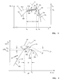
- Fig. 1 is shown as an exemplary embodiment of such an electrical implement 1, a motor chain saw 101, the electric drive motor 2, the tool 8 - in the embodiment, a saw chain 108 - with a motor-specific characteristic curve 3 ( Fig. 2 ) of the recorded motor current I over the rotational speed n drives.
- this engine-specific characteristic curve 3 gives approximately the characteristic profile of the torque M output by the electric drive motor 2 over the rotational speed n.
- n max the torque M at the output shaft approaches zero, while the current I drops to an associated no-load current.
- the characteristic 3 is intended to reproduce approximately both the motor current I over the rotational speed n and the torque M over the rotational speed n.
- the characteristic curve 3 is shown substantially linearly in the exemplary embodiment; other characteristic curves can be expedient.
- the portable hand-held implement 1 can also be used as a hedge trimmer, cut-off machine, brush cutter, edge trimmer, pruner, sprayer, blower or vacuum, earth auger, multi-purpose attachment, sweeper, tiller, tiller, lawn mower, scarifier, shredder, wet or dry vacuum cleaner, Olive shaker or the like.
- Electric implement 1 with a tool 8 be.
- Essential is a driven by the electric drive motor 2 tool 8, which is in use by the user is loaded with a feed force F to achieve a desired performance. Due to the feed force F and the power P s ( FIG. Fig. 4 ) decreases the speed n of the drive motor 2, which would lead to a larger motor current I and thus to a higher torque M on the engine-specific characteristic curve 3 system.
- the electric drive motor 2 of the implement 1 according to Fig. 1 is controlled via an electronic control unit 4, to which the electronic control unit 4 is connected on the one hand to a power supply line 5 and on the other hand to a signal line 6 to the electric drive motor 2. Control signals are applied via the signal line 6 or the rotational speed n of the electric drive motor 2 is transmitted to the control unit 4.
- the electric drive motor 2 is preferably a brushless DC motor (EC motor) and is electronically commutated via the control unit 4 in a conventional manner.
- the electrical energy for operation of the drive motor 2 is provided by a battery pack 7, which is constructed in the illustrated embodiment of lithium-based single cells with a cell voltage between 2 volts and 5 volts.
- a battery pack 7 can also be made up of NiCd cells (nickel-cadmium cells), NiMh cells (nickel-metal hydride cells) or the like.
- the electric drive motor 2 can also be supplied via the control unit 4 and a supply cable 107 directly from an electrical supply network.
- Characteristic of an electric drive motor 2 is the course of the engine-specific characteristic curve 3 in Fig. 2 ; At high speed n max (idling speed), the recorded motor current I or the output torque M of the electric drive motor 2 is low. Is by load of the driven working tool 8 - Example by applying a feed force F - braked by the drive motor 2 driven working tool 8, in the illustrated embodiment, a circulating on a guide rail 109 saw chain 108, the speed n of the driving drive motor 2 decreases, with the result that the recorded motor current I and the motor torque M. increases. As a tool 8, in particular a cutting tool is provided, such. As a driven over a sprocket saw chain 108 in a motor chain saw, a blade in a power cutter, a knife blade at a brushcutter, etc. ..
- the current I deviating from the curve of the engine-specific characteristic curve 3 is reduced below an intervention rotational speed n E by the control unit 4.
- the current I flowing through the electric drive motor 2 is limited to quantities which lie below the motor-specific characteristic curve 3.
- the control of the current I can be done by changing the motor supply voltage.
- a control characteristic 10 through which the electrical input power P M of the electric drive motor 2 is reduced in a predetermined speed range .DELTA.n to an approximately equal or slightly decreasing average input power P R.
- the control characteristic curve 10 in the rotational speed range ⁇ n is designed with a characteristic section 10d in such a way that the torque curve 11 rises above the rotational speed n in a curve section 11d in the predetermined rotational speed range ⁇ n of the working region A with decreasing rotational speed n.
- This design of the torque curve 11 in the range of the speed range .DELTA.n of the working range A advantageously takes place via a change in the motor current I.
- an increase of the torque M is set by about 5%.
- the slope of the characteristic section 11 d of the torque curve 11 can be selected to the size of the slope of the engine-specific characteristic curve 3, ie over a gradient range of the angle 45 in Fig. 2 which lies between the characteristic section 11d and the characteristic curve 3.
- the design is expediently such that the electrical input power P M drops by approximately 15% to 30%, preferably approximately 18%, starting from a maximum value.
- the falling at a falling speed n curve portion 10d of the control characteristic 10 advantageously has a pitch angle 43rd
- the speed band ⁇ n of the working range A is in the range of the engagement speed n E up to a maximum speed n H ; expediently, the rotational speed range ⁇ n is determined by the rotational speed difference between the engagement rotational speed n E and a rotational speed n 2 .
- the speed n 2 is defined by a curve point 60 of the control characteristic 10, from which the control characteristic 10 drops steeply or the torque curve 11 kinks from the engine-specific characteristic curve 3 and drops steeply down to zero.
- the speed band ⁇ n of the working range A is above an engine speed n of about 50%, advantageously above 60% of the maximum idling speed n max .
- a speed band of the working range of the driven tool preferably has a bandwidth of 500 to 2,000 revolutions / minute, in particular 1,000 revolutions / minute.
- the speed is suitably based on the tool 8, such. B. on a saw chain 108 driving sprocket or a blade bearing shaft of a cutting grinder.
- the control characteristic curve 10 or the torque curve M is designed such that a maximum rotational speed n H of the drive motor 2 is limited to a value below the maximum rotational speed n max of the engine-specific characteristic curve 3.
- the control characteristic 10 is designed so that the torque M (motor current I) has a first characteristic section 11 a, which runs from n H steeply up to a curve point 50 on the engine-specific characteristic curve 3.
- the slope of the curve portion 11 a is formed over a narrow speed range n H -n 2 of a few hundred revolutions / minute;
- the speed range n H -n 2 extends over 200 to 300 revolutions / minute. From a low Coming speed n, the characteristic section 11 a drops steeply to zero to a minimum value.
- the torque curve 11 runs from the curve point 50 on the engine-specific characteristic curve 3 to a curve point 51, in order then to run with a lesser slope from the characteristic curve 3 to a curve point 52 in the rotation speed range ⁇ n of the working region A.
- control characteristic 10 of the electrical input power P M steeply ascends as the rotational speed n decreases from a minimum input power along a curve section 10a to a curve point 60 above the curve point 50 of the torque curve M.
- the curve segment 10b of the control curve 10 adjoining at a lower slope ensures that the Torque curve M with a curve portion 11b on the curve 3 runs, and then on the basis of the curve point 61 due to the along the characteristic section 10c further reduced input power P M to force a deviation of the torque curve M in the characteristic section 11c below the characteristic curve 3.
- the curve section 10c rises up to a curve point 62 of highest input power P M , in order then to remain approximately the same (dotted line 40) along the curve section 10d according to the predetermined control characteristic 10 or to drop to a minimum value 63.
- the design is such that, despite a constant or decreasing input power P M within the speed band ⁇ n of the working range A, the torque M increases along the curve portion 11d to a maximum value 53.
- the increase of the torque M results despite decreasing input power P M by the falling speed n, wherein the control unit 4, the current I only moderately penetrate to control the input power P M , so that the user in the work area A (engagement speed n E ) no significant power dip finds.
- At the lower end of the speed band ⁇ n of the working range A there is a simple current limitation, so that torque M (or the current I) and the power P M follow the respective falling curve sections 10e and 11e.
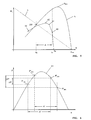
- Fig. 3 the speed band ⁇ n of the working range A in the respective transitions is shown in more detail. Same curve sections and curve points are provided with the same reference numerals.
- the characteristic section 10c merges into the curve section 10d in the speed band ⁇ n with a peak 66 which forms the maximum of the input power P M (curve point 62).
- the curve section 10d of the control characteristic curve 10 is designed such that an approximately equal or slightly fluctuating average power P R is set via the speed band ⁇ n.
- a fluctuation of the input power by the average power P R of ⁇ 15% may be permitted, preferably less than ⁇ 10%. This results in a bandwidth B of the average power P R. If the curve section 10d of the control characteristic curve 10 is designed to drop, then the mean electrical power consumed falls as a falling speed n from a maximum value in the curve point 62 to a minimum value in the curve point 63.
- the input power P M at the curve point 63 is about 80% to 95% of the input power P M at the curve point 62.
- the thus designed control characteristic 10 leads to a special shape of the power curve 20 of the cutting power P S over the feed force F, as in Fig. 4 is shown.
- the cutting power curve 20 of a driven by an electric motor 2 working tool 8 would theoretically increase steadily along the dashed curve 19. In this case, the cutting power P S increases steadily with increasing feed force F. A tactile workspace can not be detected by the user.
- the cutting power curve 20 is changed in such a way that a cutting power plateau 21 over the feed force F is formed, whose one end 22 changes into a sloping curve portion 20e when the feed force F increases. It may be advantageous to form the sloping curve section 20e as a returning curved section 20d.
- the curve portions 20b and 20c of the designed cutting power curve 20 define approximately the cutting power plateau 21 of the working area A, which can be palpable by the user by applying the feed force F and kept light.
- the tool 8 namely the saw chain 108 runs first with a predetermined by the control curve 10 maximum speed n H.
- the input electric power P M increases steeply due to the steep characteristic section 10a; this corresponds to the increasing cutting power in the rising cam branch 20a of the unchanged cutting power curve 20 (FIG. Fig. 4 ).
- the control curve 10 passes through the characteristic sections 10b and 10c, wherein the torque curve 11 is initially on the engine-specific characteristic curve 3.
- the maximum input power P M peak 66
- the cutting power curve 20 has reached the maximum cutting power P S2 at point 162.
- the first break point 161 of the cutting power curve 20 from the curve section 20a to the curve section 20b up to the point 162 of the maximum cutting power P S2 (peak 66) corresponds in the diagram to Fig. 2 the curve point 62 of the input power P M.
- the torque M of the motor 2 simultaneously rises above the falling rotational speed n, whereby Fig. 4 ) the cutting power plateau 21 is formed.
- the cutting power P S changes in only a narrow bandwidth ⁇ P S.
- the cutting power plateau 21 drops at a low angle 23 of a few degrees.
- a gate is started at maximum speed n H and then the feed force F is increased, wherein with increasing feed force the operating point of the motor chainsaw on the rising cam branch 20 a of the cutting power curve 20 (FIGS. Fig. 4 ) high on a maximum cutting power P S2 is running.
- the highest cutting power Ps at the highest point of the cutting power plateau 21 is reached. If the feed force from F 1 to F 2 further increases, the operating point in the working area A moves in the range of the cutting power plateau 21. If a feed force F is applied, which is significantly greater than the maximum feed force F 2 at the end of the cutting power plateau 21, the operating point runs in the sloping curve section 20e or 20d with sharply decreasing cutting power P S.
- the returning curve section 20d has approximately the same pitch as the curve branch 20a of the cutting power curve 20 rising to the cutting power plateau 21.
- the cutting power plateau 21 is formed with a slight pitch 23, wherein the pitch 23 is selected such that it drops with increasing feed force F.
- the pitch 23 is selected such that it drops with increasing feed force F.
- the design of the control characteristic 10 according to the Figures 2 and 3 conditionally the shape of the cutting power curve 20 according to Fig. 4 ,
- Such a designed cutting power curve does not result in a drive of a tool, in particular a cutting tool by an electric drive motor 2 on a motor-specific characteristic.
- the design of the control characteristic curve 10 is such that in the working area A, the rotational speed of the electric motor is in a range which ensures sufficient cooling of the electric drive motor 2 even under load.
- the design of the cutting power curve according to Fig. 4 encourages the user to select the operating point in the region of the cutting power plateau 21 to obtain a maximum cutting power P S , which is a speed in the range between n E and n 2 (FIG. Fig. 2 ) ensures, in which a thermal overload of the electric drive motor can be safely excluded.
- the trained cutting power plateau 21 is below a continuous power limit 44 of a thermal overload range.
- the control unit 4 enforces the control characteristic 10 according to the invention, wherein in the working area A, the curve portion falling between n 1 and n E is reduced to an average input power P at falling speed n.
- Fig. 5 the efficiency ⁇ is shown, which rises above the rotational speed n up to a maximum ⁇ max , in order then to drop to a torque M towards zero at a maximum rotational speed n max .
- Fig. 5 the control characteristic 10 is shown with the curve points 60, 61 and 62, wherein the working range A between the engagement speed n E and an upper speed n 2 is located.
- the speed band ⁇ n of the working range A is determined from the difference between the upper speed n 2 and the engagement speed n E , that is, n 2 -n E.
- the engine efficiency at point 100 is approximately 75% to 78% of the maximum efficiency ⁇ max and increases in the operating range A with increasing speed n.
- the increase of the efficiency ⁇ within the working range A is possible close to the maximum efficiency ⁇ max ; expediently an efficiency ⁇ of up to 95% of the maximum efficiency ⁇ max is achieved in the working area A.
- Fig. 6 is schematically represent a power curve P *.
- P * z.
- B a work area A 'or A "selected, each work area by a minimum power P' min or P" min and a maximum power P ' max or P " max is characterized.
- control characteristic 10 ( Fig. 2 ) is set to an approximately equal average power P R in the work area A, then this same average power P R is chosen to correspond to the natural minimum power of the natural power curve P *. That is, in a work area A ', the set average power P R corresponds to the minimum power P' min of the natural power curve P *; if a work area A "is provided, the same average power P R to be set is set to the minimum power P" min of the work area A. "Depending on the location of the work area, the minimum power P min on both the ascending and descending curve branches the natural power curve P * lie.
- the drive motor 1 drives a tool, in particular a cutting tool. If the implement 1 is designed as a motor chain saw, the cutting tool is a saw chain.
- the electric drive motor 1 of the implement is generally powered by a battery pack, d. h., supplied with electrical energy.
Abstract
Description
Die Erfindung betrifft ein handgeführtes Arbeitsgerät mit einem elektrischen Antriebsmotor, insbesondere eine elektrische Motorkettensäge nach dem Oberbegriff des Anspruchs 1.The invention relates to a hand-held implement with an electric drive motor, in particular an electric motor chain saw according to the preamble of
Aus der
Elektromotoren haben generell eine Motorstrom- bzw. Drehmomentkennlinie, die bei niedrigen Drehzahlen eine hohe Stromaufnahme und bei hohen Drehzahlen eine niedrige Stromaufnahme bzw. Drehmoment zeigt. Da eine hohe Stromaufnahme zu einem hohen, von dem Elektromotor abgegebenen Drehmoment führt, wird ein Benutzer, der ein elektrisches Arbeitsgerät mit einem Werkzeug führt, mit steigender Vorschubkraft eine immer höhere Schnittleistung erzielen. Als Antwort auf eine steigende Vorschubkraft und ein langsamer werdendes Werkzeug (fallende Motordrehzahl) gibt der Elektromotor ein höheres Drehmoment ab, weshalb der Benutzer subjektiv eine höhere Schnittleistung empfindet. Aufgrund des typischen Kennlinienverlaufs des Elektromotors ist es für den Benutzer schwierig, durch Steuerung der Vorschubkraft einen geeigneten Arbeitsbereich mit gutem Wirkungsgrad sicher anzufahren und zu halten.Electric motors generally have a motor current or torque characteristic, which shows a high power consumption at low speeds and low power consumption or torque at high speeds. Since a high current consumption leads to a high torque output by the electric motor, a user who carries an electric working tool with a tool will achieve an ever higher cutting performance with increasing feed force. In response to an increasing feed force and a slower tool (falling engine speed), the electric motor outputs a higher torque, which is why the user subjectively higher cutting power feels. Due to the typical characteristic curve of the electric motor, it is difficult for the user to safely approach and hold a suitable working area with good efficiency by controlling the feed force.
Der Erfindung liegt die Aufgabe zugrunde, ein Arbeitsgerät mit einem elektrischen Antriebsmotor derart auszubilden, dass ein Benutzer auf einfache Weise einen Arbeitsbereich des Arbeitsgerätes mit gutem Wirkungsgrad anfahren und im Betrieb sicher halten kann.The invention has for its object to form a working device with an electric drive motor such that a user can easily approach a working area of the implement with good efficiency and keep safe in operation.
Diese Aufgabe wird erfindungsgemäß nach den Merkmalen des Anspruchs 1 gelöst.This object is achieved according to the features of
In einem Arbeitsbereich oberhalb der Eingriffsdrehzahl zur Begrenzung des Motorstroms wird in einem vorgegebenen Drehzahlband von der Steuereinheit eine Steuerkennlinie vorgegeben, nach der die Eingangsleistung des elektrischen Antriebsmotors in dem vorgegebenen Drehzahlband auf eine etwa gleiche mittlere Leistung reduziert ist. Die Änderung der Leistung in dem vorgegebenen Drehzahlband ist so gestaltet, dass bei sinkender Drehzahl in dem vorgegebenen Drehzahlband das Drehmoment des Antriebsmotors ansteigt.In a working range above the engagement speed for limiting the motor current, a control characteristic is predetermined in a predetermined speed band by the control unit, according to which the input power of the electric drive motor in the predetermined speed band is reduced to an approximately equal average power. The change in power in the predetermined speed band is designed so that with decreasing speed in the predetermined speed range, the torque of the drive motor increases.
Die in dieser Form vorgenommene Gestaltung der Steuerkennlinie führt zu einem durch den Benutzer leicht anfahrbaren Arbeitsbereich, der aufgrund des gegenläufigen Verhaltens von mittlerer Leistung und Drehmoment vom Benutzer über einen vorgegebenen Drehzahlbereich leicht angefahren und gehalten werden kann. Die Auslegung des Arbeitsbereichs ist dabei so gewählt, dass der verwendete Elektromotor mit einem guten bis optimalen Wirkungsgrad betrieben ist.The design of the control characteristic in this form results in a work area easily approachable by the user, which can be easily approached and maintained by the user over a given range of speeds due to the adverse behavior of average power and torque. The design of the work area is chosen so that the electric motor used is operated with a good to optimal efficiency.
In zweckmäßiger Ausbildung ist die Drehmomentkennlinie des Antriebsmotors im Drehzahlband derart ausgebildet, dass bei sinkender Drehzahl das Drehmoment im relevanten Arbeitsbereich um mindestens etwa 5% ansteigt, vorzugsweise um mindestens 15%. Eine reduzierte, etwa gleiche mittlere Leistung entspricht vorteilhaft in der Größe etwa der natürlichen minimalen Leistung des elektrischen Antriebsmotors in einem ausgewählten Arbeitsbereich.In an expedient embodiment, the torque characteristic of the drive motor in the speed band is designed such that with decreasing speed, the torque in the relevant working range increases by at least about 5%, preferably by at least 15%. A reduced, approximately equal average power advantageously corresponds in size to approximately the natural minimum power of the electric drive motor in a selected operating range.
Zur Ausbildung eines signifikanten Arbeitsbereichs ist es vorteilhaft, wenn die elektrische Eingangsleistung des elektrischen Antriebsmotors in dem vorgegebenen Drehzahlband bei sinkender Drehzahl leicht abfällt, insbesondere von einem Maximalwert um etwa 15% bis 30%, vorzugsweise etwa 18% abfällt. Dadurch ergibt sich ein breiter, leicht anfahrbarer Arbeitsbereich mit hohem elektrischen Wirkungsgrad.To form a significant working range, it is advantageous if the electrical input power of the electric drive motor in the predetermined speed band slightly decreases with decreasing speed, in particular falls from a maximum value by about 15% to 30%, preferably about 18%. This results in a wider, easily approachable work area with high electrical efficiency.
Das vorgegebene Drehzahlband liegt oberhalb einer Motordrehzahl von etwa 50%, vorzugsweise oberhalb von etwa 60% der maximalen Leerlaufdrehzahl der motorspezifischen Kennlinie des Antriebsmotors. Die Steuerkennlinie bestimmt somit einen regelmäßig angefahrenen Betriebsbereich des Elektromotors. Insbesondere bestimmt die Steuerkennlinie eine vorgegebene Höchstdrehzahl des Antriebsmotors, die unterhalb der Maximaldrehzahl der motorspezifischen Kennlinie liegt.The predetermined speed band is above an engine speed of about 50%, preferably above about 60% of the maximum idle speed of the engine-specific characteristic of the drive motor. The control characteristic thus determines a regularly approached operating range of the electric motor. In particular, the control characteristic determines a predetermined maximum speed of the drive motor, which is below the maximum speed of the engine-specific characteristic.
In besonderer Ausgestaltung ist als Weiterbildung oder eigenständige Lösung eine Steuerkennlinie der elektrischen Eingangsleistung derart ausgebildet, dass in der Leistungskurve der Schnittleistung des Werkzeugs über der Vorschubkraft etwa ein Schnittleistungsplateau ausgebildet ist, dessen rechtes, oberes Ende bei steigender Vorschubkraft in einen abfallenden bis rücklaufenden Kurvenabschnitt übergeht.In a particular embodiment, as a development or independent solution, a control characteristic of the electrical input power is designed such that in the power curve of the cutting performance of the tool on the feed force about a Schnittleistungsplateau is formed, the right, upper end passes with increasing feed force in a sloping to return curve section.
Die Auslegung der Steuerkennlinie und die damit erzielte Beeinflussung der Eingangsleistung bzw. des aufgenommenen Stroms des Elektromotors ist genau so vorgesehen, dass die Schnittleistungskurve ein für den Benutzer im Betrieb fühlbares Schnittleistungsplateau ausbildet. Das Schnittleistungsplateau erstreckt sich über eine Bandbreite der Vorschubkraft bei etwa gleichbleibender bis leicht veränderter Schnittleistung.The design of the control characteristic and the resulting influence on the input power or the absorbed current of the electric motor is precisely provided so that the cutting power curve forms a perceptible for the user in operation Schnittleistungsplateau. The cutting power plateau extends over a range of the feed force at approximately constant to slightly modified cutting power.
Vorteilhaft ist das Schnittleistungsplateau mit geringer Steigung ausgebildet, wobei das Schnittleistungsplateau bevorzugt mit steigender Vorschubkraft abfällt. Der geübte Benutzer wird im Schnitt leicht einen Betriebspunkt auf dem Schnittleistungsplateau finden können, da eine größere Vorschubkraft zu einer signifikant sinkenden Schnittleistung führt. Der Benutzer wird folgerichtig die Vorschubkraft wieder zurücknehmen, so dass der Betriebspunkt auf dem Schnittleistungsplateau bis zu einer Maximalleistung im Bereich des Anfangs des Schnittleistungsplateaus im Übergang zur unveränderten Schnittleistungskurve verlagert wird. Erhöht der Benutzer die Vorschubkraft trotz leicht abfallender Schnittleistung weiter, wandert der Betriebspunkt am Ende des Schnittleistungsplateaus auf dem abfallenden Kurvenabschnitt abwärts oder geht in einen rücklaufenden Kurvenabschnitt der eingestellten Leistungskurve über, wodurch die Maschine signifikant an Schnittleistung einbüßt, was zu einer entsprechenden Gegenreaktion des Benutzers führt. Der rücklaufende Kurvenabschnitt hat etwa eine gleiche Steigung wie der zum Schnittleistungsplateau ansteigende Kurvenast der unveränderten Leistungskurve. Durch Absenken der Vorschubkraft führt der Benutzer den Betriebspunkt wieder auf das Schnittleistungsplateau der Schnittkurve zurück, wobei er über die Steuerung der Vorschubkraft jederzeit an das eine oder das andere Ende des Schnittleistungsplateaus fahren kann. In einfacher Weise wird der Benutzer durch die vorgegebene Steuerkennlinie der Steuereinheit zu einem Betrieb des Arbeitsgerätes im Bereich des Schnittleistungsplateaus angehalten, welches zu einer optimalen Schnittleistung führt.Advantageously, the cutting power plateau is designed with a low pitch, the cutting power plateau preferably decreasing with increasing feed force. The experienced user On average, it will be easy to find an operating point on the cutting power plateau, since a larger feed force leads to a significantly reduced cutting performance. The user will logically take back the feed force, so that the operating point is shifted on the cutting power plateau up to a maximum power in the range of the beginning of the cutting power plateau in the transition to the unchanged cutting power curve. If the user continues to increase the feed force despite slightly decreasing cutting power, the operating point at the end of the cutting capacity plateau descends on the descending curve section or enters a return curve section of the adjusted power curve, causing the machine to significantly reduce cutting performance, which leads to a corresponding backlash by the user , The returning curve section has approximately the same slope as the curve load of the unchanged power curve, which increases to the cutting power plateau. By lowering the feed force, the user returns the operating point back to the cutting power plateau of the cutting curve, where he can go over the control of the feed force at any time to one or the other end of the cutting power plateau. In a simple way, the user is stopped by the predetermined control characteristic of the control unit to an operation of the implement in the range of Schnittleistungsplateaus, which leads to an optimal cutting performance.
Ein vorgegebenes Drehzahlband des Arbeitsbereichs eines Werkzeugs liegt in einer Bandbreite von 500 bis 2.000 Umdrehungen/Minute, vorzugsweise um 1.000 Umdrehungen/Minute, wobei ein an das obere Drehzahlende des vorgegebenen Drehzahlbandes anschließender Kennlinienabschnitt über ein schmales Drehzahlband von wenigen Hundert Umdrehungen/Minute steil gegen Null abfällt. Vorzugsweise umfasst das schmale Drehzahlband etwa 200 Umdrehungen/Minute. Die Steilheit des Kennlinienabschnittes führt beim Anschnitt mit Höchstdrehzahl rasch zu einem hohen Drehmoment und entsprechend hoher Schnittleistung, so dass ein Betriebspunkt im Bereich des Schnittleistungsplateaus schnell und sicher angefahren werden kann. Die Ausgangsdrehzahl zum Werkzeug kann die Drehzahl eines das Werkzeug direkt antreibenden Elektromotors sein oder auch die Drehzahl einer Getriebeausgangswelle, die das Werkzeug in angepasster Weise antreibt.A predetermined speed range of the working range of a tool is in a range of 500 to 2,000 revolutions / minute, preferably around 1,000 revolutions / minute, with a subsequent to the upper end of the speed range of the predetermined speed range characteristic section over a narrow speed range of a few hundred revolutions / minute steeply to zero drops. Preferably, the narrow speed band comprises about 200 revolutions / minute. The steepness of the characteristic section leads quickly at high speed gating to a high torque and correspondingly high cutting performance, so that an operating point in the range of Schnittleistungsplateaus can be approached quickly and safely. The output speed to the tool may be the speed of an electric motor driving the tool directly or the speed of a transmission output shaft which drives the tool in an adapted manner.
Es kann zweckmäßig sein, die Steuerkennlinie am oberen Ende des vorgegebenen Drehzahlbandes derart zu gestalten, dass die Drehmomentkurve über einen Teilabschnitt auf der motorspezifischen Kennlinie verläuft. Die Steuerkennlinie weist im Bereich des oberen Endes des vorgegebenen Drehzahlbandes im Übergang zu einem Kurvenabschnitt mit negativer Steigung einen Peak auf, der einen optimalen Betriebspunkt maximaler Leistung kennzeichnet.It may be appropriate to make the control characteristic at the upper end of the predetermined speed band such that the torque curve extends over a partial section on the engine-specific characteristic. The control characteristic has a peak in the region of the upper end of the predetermined speed band in transition to a negative slope curve segment, which characterizes an optimum operating point of maximum power.
Darüber hinaus ist aufgrund des Betriebs des Arbeitsgerätes mit einem Betriebspunkt im Bereich des Schnittleistungsplateaus gewährleistet, dass die Drehzahl des Antriebsmotors jederzeit in einem Bereich liegt, der eine ausreichende Kühlung des Antriebsmotors sicherstellt. Der Benutzer fährt das Arbeitsgerät somit nicht nur in einem optimalen Schnittleistungsbereich, sondern auch in einem thermisch ausgeglichenen Betriebsbereich nahe der thermischen Dauerleistungsgrenze, was eine thermische Schädigung der elektrischen Antriebseinheit auch bei Dauerbetrieb ausschließt. Vorteilhaft ist die im Dauerbetrieb aufgenommene elektrische Eingangsleistung des Antriebsmotors auf etwa 25% über der durch die thermische Dauerleistungsgrenze bestimmten Eingangsleistung eingestellt.In addition, it is ensured due to the operation of the implement with an operating point in the range of Schnittleistungsplateaus that the speed of the drive motor is always in a range that ensures sufficient cooling of the drive motor. The user drives the implement not only in an optimal cutting power range, but also in a thermally balanced operating range near the thermal continuous power limit, which precludes thermal damage to the electric drive unit even in continuous operation. Advantageously, the electrical input power of the drive motor received in continuous operation is set to approximately 25% above the input power determined by the thermal continuous power limit.
Der elektrische Wirkungsgrad des Antriebsmotors ist im Arbeitsbereich vorteilhaft derart eingestellt, dass er größer als 78% des maximalen Wirkungsgrades des Elektromotors ist.The electrical efficiency of the drive motor is advantageously set in the work area such that it is greater than 78% of the maximum efficiency of the electric motor.
Weitere Merkmale der Erfindung ergeben sich aus den weiteren Ansprüchen, der Beschreibung und der Zeichnung, in der ein nachfolgend im Einzelnen beschriebenes Ausführungsbeispiel der Erfindung dargestellt ist. Es zeigen:
- Fig. 1
- in schematischer Darstellung ein Arbeitsgerät mit von einem elektrischen Antriebsmotor angetriebenen Werkzeug am Beispiel einer Motorkettensäge,
- Fig. 2
- ein Schaubild zum Verlauf der elektrischen Eingangsleistung sowie des Strom-/Drehmomentverlaufes über der Drehzahl,
- Fig. 3
- in vergrößerter Darstellung ein Detail III des Schaubildes aus
Fig. 2 , - Fig. 4
- ein Schnittleistungsdiagramm eines elektrisch angetriebenen Werkzeugs am Beispiel der Sägekette einer Motorkettensäge;
- Fig. 5
- ein Schaubild des Wirkungsgrades des elektrischen Motors über der Drehzahl;
- Fig. 6
- eine Leistungskurve der über der Drehzahl am Werkzeug abgegebenen mechanischen Leistung.
- Fig. 1
- 1 a working device with a tool driven by an electric drive motor using the example of a motor chain saw,
- Fig. 2
- a diagram for the course of the electrical input power and the current / torque curve over the speed,
- Fig. 3
- in enlarged view a detail III of the graph
Fig. 2 . - Fig. 4
- a sectional power diagram of an electrically driven tool using the example of the saw chain of a motor chain saw;
- Fig. 5
- a graph of the efficiency of the electric motor over the speed;
- Fig. 6
- a power curve of over the speed delivered to the tool mechanical power.
Die Erfindung betrifft allgemein ein elektrisches, handgeführte Arbeitsgerät 1 mit einem angetriebenen Werkzeug 8. In
Das tragbare, handgeführte Arbeitsgerät 1 kann auch als Heckenschere, Trennschleifer, Freischneider, Kantenschneider, Hochentaster, Sprühgerät, Blas- oder Sauggerät, Erdbohrgerät, Kombimotorgerät für multifunktionelle Vorsätze, Kehrgerät, Motorhacke, Bodenfräse, Rasenmäher, Vertikutierer, Häcksler, Nass- oder Trockensauger, Olivenschüttler oder dgl. elektrisches Arbeitsgerät 1 mit einem Werkzeug 8 sein. Wesentlich ist ein vom elektrischen Antriebsmotor 2 angetriebenes Werkzeug 8, das im Arbeitseinsatz vom Benutzer mit einer Vorschubkraft F belastet wird, um eine gewünschte Arbeitsleistung zu erzielen. Durch die Vorschubkraft F und die am Werkzeug 8 erbrachte Leistung Ps (
Der elektrische Antriebsmotor 2 des Arbeitsgerätes 1 nach
Im gezeigten Ausführungsbeispiel ist die elektrische Energie zum Betrieb des Antriebsmotors 2 durch einen Akkupack 7 zur Verfügung gestellt, der im gezeigten Ausführungsbeispiel aus auf Lithium basierenden Einzelzellen mit einer Zellspannung zwischen 2 Volt und 5 Volt aufgebaut ist. So sind zweckmäßig LiIo-Zellen (Lithium-Ionen-Zellen), LiPo-Zellen (Lithium-Polymer-Zellen), LiFePo4-Zellen (Lithium-Eisen-Phosphat-Zellen), Lithium-Titanat-Zellen oder dgl. Zellen in Reihen- und/oder Parallelschaltung verwendet. Der Akkupack 7 kann auch aus NiCd-Zellen (Nickel-Cadmium-Zellen), NiMh-Zellen (Nickel-Metallhydrid-Zellen) oder dgl. Zellen aufgebaut sein. Anstelle einer elektrischen Versorgung des Antriebsmotors 2 aus einem Akkupack geeigneten Aufbaus kann der elektrische Antriebsmotor 2 auch über die Steuereinheit 4 und ein Versorgungskabel 107 direkt aus einem elektrischen Versorgungsnetz gespeist werden.In the illustrated embodiment, the electrical energy for operation of the drive motor 2 is provided by a
Charakteristisch für einen elektrischen Antriebsmotor 2 ist der Verlauf der motorspezifischen Kennlinie 3 in
Um einen zu großen Stromanstieg bei niedrigen Drehzahlen n zu vermeiden, wird unterhalb einer Eingriffsdrehzahl nE durch die Steuereinheit 4 der Strom I abweichend vom Verlauf der motorspezifischen Kennlinie 3 reduziert. Dadurch ist der durch den elektrischen Antriebsmotor 2 fließende Strom I auf Größen begrenzt, die unterhalb der motorspezifischen Kennlinie 3 liegen. Die Steuerung des Stroms I kann durch eine Veränderung der Motorversorgungsspannung erfolgen.In order to avoid too great a current increase at low rotational speeds n, the current I deviating from the curve of the engine-specific
In einem Arbeitsbereich A (
Wird im Drehzahlband Δn des Arbeitsbereiches A eine abfallende Eingangsleistung PM des elektrischen Antriebsmotors 2 vorgesehen, so ist die Auslegung zweckmäßig so getroffen, dass die elektrische Eingangsleistung PM ausgehend von einem Maximalwert um etwa 15% bis 30%, vorzugsweise etwa 18% abfällt. Der bei sinkender Drehzahl n abfallende Kurvenabschnitt 10d der Steuerkennlinie 10 hat vorteilhaft einen Steigungswinkel 43.If a decreasing input power P M of the electric drive motor 2 is provided in the rotational speed range Δn of the working range A, the design is expediently such that the electrical input power P M drops by approximately 15% to 30%, preferably approximately 18%, starting from a maximum value. The falling at a falling speed
Das Drehzahlband Δn des Arbeitsbereiches A liegt im Bereich der Eingriffsdrehzahl nE bis zu einer Höchstdrehzahl nH; zweckmäßig ist das Drehzahlband Δn durch den Drehzahlabstand zwischen der Eingriffsdrehzahl nE und einer Drehzahl n2 bestimmt. Die Drehzahl n2 ist durch einen Kurvenpunkt 60 der Steuerkennlinie 10 definiert, ab dem die Steuerkennlinie 10 steil abfällt bzw. die Drehmomentkurve 11 von der motorspezifischen Kennlinie 3 abknickt und steil nach unten gegen Null abfällt.The speed band Δn of the working range A is in the range of the engagement speed n E up to a maximum speed n H ; expediently, the rotational speed range Δn is determined by the rotational speed difference between the engagement rotational speed n E and a rotational speed n 2 . The speed n 2 is defined by a
Das Drehzahlband Δn des Arbeitsbereiches A liegt oberhalb einer Motordrehzahl n von etwa 50%, vorteilhaft oberhalb von 60% der maximalen Leerlaufdrehzahl nmax. Ein Drehzahlband des Arbeitsbereichs des angetriebenen Werkzeugs weist vorzugsweise eine Bandbreite von 500 bis 2.000 Umdrehungen/Minute auf, insbesondere 1.000 Umdrehungen/Minute. Dabei ist die Drehzahl zweckmäßig auf das Werkzeug 8 bezogen, so z. B. auf ein die Sägekette 108 antreibendes Kettenrad oder die eine Trennscheibe tragende Welle eines Trennschleifers. Die Steuerkennlinie 10 bzw. die Drehmomentkurve M ist derart ausgelegt, dass eine Höchstdrehzahl nH des Antriebsmotors 2 auf einen Wert unterhalb der Maximaldrehzahl nmax der motorspezifischen Kennlinie 3 begrenzt ist. Ausgehend von dieser Höchstdrehzahl nH des Antriebsmotors 2 ist die Steuerkennlinie 10 so gestaltet, das das Drehmoment M (Motorstrom I) einen ersten Kennlinienabschnitt 11 a aufweist, der von nH steil nach oben bis auf einen Kurvenpunkt 50 auf der motorspezifischen Kennlinie 3 verläuft. Der Anstieg des Kurvenabschnitts 11 a ist über einen schmalen Drehzahlbereich nH-n2 von wenigen Hundert Umdrehungen/Minute ausgebildet; vorzugsweise erstreckt sich der Drehzahlbereich nH-n2 über 200 bis 300 Umdrehungen/Minute. Von einer niedrigen Drehzahl n kommend fällt der Kennlinienabschnitt 11 a steil gegen Null auf einen Minimalwert ab.The speed band Δn of the working range A is above an engine speed n of about 50%, advantageously above 60% of the maximum idling speed n max . A speed band of the working range of the driven tool preferably has a bandwidth of 500 to 2,000 revolutions / minute, in particular 1,000 revolutions / minute. The speed is suitably based on the tool 8, such. B. on a
Vom steilen Kennlinienabschnitt 11a kommend, verläuft die Drehmomentkurve 11 vom Kurvenpunkt 50 auf der motorspezifischen Kennlinie 3 bis zu einem Kurvenpunkt 51, um dann mit geringerer Steigung von der Kennlinie 3 abweichend zu einem Kurvenpunkt 52 in dem Drehzahlband Δn des Arbeitsbereiches A zu verlaufen.Coming from the steep
Entsprechend verläuft die Steuerkennlinie 10 der elektrischen Eingangsleistung PM bei sinkender Drehzahl n von einer minimalen Eingangsleistung längs eines Kurvenabschnitts 10a steil aufwärts auf einen Kurvenpunkt 60 oberhalb des Kurvenpunktes 50 der Drehmomentkurve M. Der mit geringerer Steigung anschließende Kurvenabschnitt 10b der Steuerkennlinie 10 gewährleistet, dass die Drehmomentkurve M mit einem Kurvenabschnitt 11b auf der Kennlinie 3 verläuft, um dann ausgehend vom Kurvenpunkt 61 aufgrund der längs des Kennlinienabschnittes 10c weiter reduzierter Eingangsleistung PM ein Abweichen der Drehmomentkurve M in dem Kennlinienabschnitt 11c unterhalb der Kennlinie 3 zu erzwingen. Der Kurvenabschnitt 10c steigt bis zu einem Kurvenpunkt 62 höchster Eingangsleistung PM an, um dann gemäß der vorgegebenen Steuerkennlinie 10 längs des Kurvenabschnitts 10d etwa gleich zu bleiben (punktierte Linie 40) oder auf einen Minimalwert 63 abzufallen. Die Auslegung ist so getroffen, dass trotz gleichbleibender oder abfallender Eingangsleistung PM innerhalb des Drehzahlbandes Δn des Arbeitsbereiches A das Drehmoment M längs des Kurvenabschnitts 11d bis auf einen Mamimalwert 53 ansteigt. Der Anstieg des Drehmomentes M ergibt sich trotz sinkender Eingangsleistung PM durch die abfallende Drehzahl n, wobei zur Steuerung der Eingangsleistung PM die Steuereinheit 4 den Strom I nur moderat zurückfährt, so dass der Benutzer im Arbeitsbereich A (Eingriffsdrehzahl nE) keinen wesentlichen Leistungseinbruch feststellt. Am unteren Ende des Drehzahlbandes Δn des Arbeitsbereiches A erfolgt eine einfache Strombegrenzung, so dass Drehmoment M (bzw. der Strom I) und die Leistung PM den jeweiligen abfallenden Kurvenabschnitten 10e und 11e folgen.Correspondingly, the
In
Die so gestaltete Steuerkennlinie 10 führt zu einer besonderen Form der Leistungskurve 20 der Schnittleistung PS über der Vorschubkraft F, wie sie in
Durch die Ausbildung der Steuerkennlinie 10 gemäß den
Die Kurvenbereiche 20b und 20c der gestalteten Schnittleistungskurve 20 definieren in etwa das Schnittleistungsplateau 21 des Arbeitsbereichs A, das vom Benutzer durch Aufbringen der Vorschubkraft F fühlbar angefahren und leicht gehalten werden kann.The
Wird das Arbeitsgerät 1, z. B. eine Motorkettensäge 101 in Betrieb genommen, läuft das Werkzeug 8, nämlich die Sägekette 108 zunächst mit einer durch die Steuerkennlinie 10 vorgeprägten Höchstdrehzahl nH. Mit Belastung des angetriebenen Werkzeugs 8 durch Aufbringen einer Vorschubkraft F steigt die elektrische Eingangsleistung PM aufgrund des steilen Kennlinienabschnitts 10a steil an; dies entspricht der ansteigenden Schnittleistung im ansteigenden Kurvenast 20a der unveränderten Schnittleistungskurve 20 (
Erhöht der Benutzer die Vorschubkraft F weiter (
Bei einer Motorkettensäge wird ein Anschnitt bei Höchstdrehzahl nH begonnen und dann die Vorschubkraft F erhöht, wobei mit steigender Vorschubkraft der Betriebspunkt der Motorkettensäge über den ansteigenden Kurvenast 20a der Schnittleistungskurve 20 (
Bevorzugt ist das Schnittleistungsplateau 21 mit geringer Steigung 23 ausgebildet, wobei die Steigung 23 derart gewählt ist, dass sie bei steigender Vorschubkraft F abfällt. Dies hat zur Folge, dass bei Erhöhen der Vorschubkraft der Benutzer bei Übergang des Betriebspunktes auf den abfallenden Kurvenabschnitt einen deutlichen Abfall der Schnittleistung PS feststellt und somit das Ende des Arbeitsbereiches im Bereich des Endes 22 des Kurvenabschnittes 20c ertasten bzw. fühlen kann. Nimmt er die Vorschubkraft F zurück, steigt die Schnittleistung auf dem Schnittleistungsplateau 21 bis zum Maximalpunkt 162 wieder an, so dass der Benutzer durch Wahl der Vorschubkraft F das Arbeitsgerät in einfacher Weise in einem optimalen Arbeitsbereich A betreiben kann.Preferably, the cutting
Die Gestaltung der Steuerkennlinie 10 gemäß den
Die Auslegung der Steuerkennlinie 10 erfolgt so, dass im Arbeitsbereich A die Drehzahl des Elektromotors in einem Bereich liegt, der auch unter Last eine ausreichende Kühlung des elektrischen Antriebsmotors 2 gewährleistet. Die Gestaltung der Schnittleistungskurve gemäß
Die Steuereinheit 4 erzwingt die erfindungsgemäße Steuerkennlinie 10, wobei im Arbeitsbereich A der bei sinkender Drehzahl n abfallende Kurvenabschnitt zwischen n1 und nE auf eine mittlere Eingangsleistung P zurückgeführt ist.The
In
In
Im Bereich der Eingriffsdrehzahl nE liegt der Motorwirkungsgrad im Punkt 100 bei etwa 75% bis 78% des maximalen Wirkungsgrades ηmax und steigt im Arbeitsbereich A mit steigender Drehzahl n an. Der Anstieg des Wirkungsgrades η innerhalb des Arbeitsbereiches A ist bis nahe an den maximalen Wirkungsgrad ηmax möglich; zweckmäßig wird im Arbeitsbereich A ein Wirkungsgrad η von bis zu 95% des maximalen Wirkungsgrades ηmax erzielt.In the range of the engagement speed n E , the engine efficiency at
Im Ausführungsbeispiel nach
Wird die Steuerkennlinie 10 (
Nach der Erfindung treibt der Antriebsmotor 1 ein Werkzeug an, insbesondere ein Schneidwerkzeug. Ist das Arbeitsgerät 1 als Motorkettensäge ausgebildet, ist das Schneidwerkzeug eine Sägekette. Der elektrische Antriebsmotor 1 des Arbeitsgerätes wird allgemein von einem Akkupack gespeist, d. h., mit elektrischer Energie versorgt.According to the invention, the
Claims (16)
dadurch gekennzeichnet, dass in einem Arbeitsbereich (A) mit einem vorgegebenen Drehzahlband (Δn) oberhalb der Eingriffsdrehzahl (nE) von der Steuereinheit (4) eine Steuerkennlinie (10) der elektrischen Eingangsleistung (P) des elektrischen Antriebsmotors (2) über der Drehzahl (n) vorgegeben ist, nach der die Eingangsleistung (P) in dem vorgegebenen Drehzahlband (Δn) auf eine etwa gleiche mittlere Leistung (PR) derart reduziert ist, dass in dem vorgegebenen Drehzahlband (Δn) bei sinkender Drehzahl (n) das Drehmoment (M) des Antriebsmotors (2) ansteigt.Hand-operated implement with an electric drive motor (1), in particular electric motor chainsaw (101), wherein the electric drive motor (2) has a motor-specific characteristic (3) of the recorded motor current (I) over the speed (n) of the motor (2), and with a control unit (4), via which the electrical drive motor (2) supplied electrical energy is controlled, wherein the control unit (4) below an engagement speed (n E ) by the electric drive motor (2) flowing current (I) to values limited, which are below the engine-specific characteristic (3),
characterized in that in a work area (A) with a predetermined speed band (Δn) above the engagement speed (n E ) of the control unit (4) a control characteristic (10) of the electrical input power (P) of the electric drive motor (2) above the speed (n) is predetermined, according to which the input power (P) in the predetermined speed band (Δn) to an approximately equal average power (P R ) is reduced such that in the predetermined speed band (Δn) with decreasing speed (n) the torque (M) of the drive motor (2) increases.
dadurch gekennzeichnet, dass das Drehmoment (M) des Antriebsmotors (2) im Drehzahlband (Δn) bei sinkender Drehzahl (n) um etwa 5% ansteigt, vorzugsweise um bis zu 15% ansteigt.Working device according to claim 1,
characterized in that the torque (M) of the drive motor (2) increases in the speed band (Δn) with decreasing speed (n) by about 5%, preferably by up to 15%.
dadurch gekennzeichnet, dass die reduzierte, etwa gleiche mittlere Leistung (PR) etwa der natürlichen minimalen Leistung (P'min, P"min) des elektrischen Antriebsmotors (2) in einem ausgewählten Arbeitsbereich (A', A") entspricht.Tool according to claim 1 or 2,
characterized in that the reduced, approximately equal average power (P R ) corresponds approximately to the natural minimum power (P ' min , P " min ) of the electric drive motor (2) in a selected operating range (A', A").
dadurch gekennzeichnet, dass die elektrische Eingangsleistung (P) des elektrischen Antriebsmotors (2) in dem vorgegebenen Drehzahlband (Δn) über einen Kennlinienabschnitt (10d) der Steuerkennlinie (10) bei sinkender Drehzahl (n) leicht abfällt, wobei vorzugsweise die elektrische Eingangsleistung (P) ausgehend von einem Maximalwert (62) um etwa 15% bis 30%, insbesondere etwa 18% abfällt.Tool according to claim 1 or 2,
characterized in that the electrical input power (P) of the electric drive motor (2) in the predetermined speed band (Δn) over a characteristic section (10d) of the control characteristic (10) slightly decreases with decreasing speed (n), wherein preferably the electrical input power (P ) decreases from about a maximum value (62) by about 15% to 30%, in particular about 18%.
dadurch gekennzeichnet, dass das vorgegebene Drehzahlband (Δn) oberhalb einer Motordrehzahl (n) von etwa 50%, vorzugsweise etwa 60% der maximalen Leerlaufdrehzahl (nmax) der motorspezifischen Kennlinie (3) des Antriebsmotors (2) liegt.Tool according to one of claims 1 to 4,
characterized in that the predetermined speed band (Δn) above an engine speed (n) of about 50%, preferably about 60% of the maximum idling speed (n max ) of the engine-specific characteristic (3) of the drive motor (2).
dadurch gekennzeichnet, dass die Steuerkennlinie (10) die Höchstdrehzahl (nH) des Antriebsmotors (2) auf einen Wert unterhalb der Maximaldrehzahl (nmax) der motorspezifischen Kennlinie (3) begrenzt.Tool according to one of claims 1 to 5,
characterized in that the control characteristic (10) limits the maximum speed (n H ) of the drive motor (2) to a value below the maximum speed (n max ) of the engine-specific characteristic (3).
insbesondere nach den Merkmalen des Oberbegriffs des Anspruchs 1, dadurch gekennzeichnet, dass eine vorgegebene Steuerkennlinie (10) der elektrischen Eingangsleistung (PM) derart ausgelegt ist, dass in einer Leistungskurve (20) der Schnittleistung (PS) eines Werkzeugs (8) über der Vorschubkraft (F) ein Schnittleistungsplateau (21) ausgebildet ist, dessen rechtes, oberes Ende (22) bei steigender Vorschubkraft (F) in einen abfallenden Kurvenabschnitt (20d, 20e) übergeht.Tool according to one of claims 1 to 6,
in particular according to the features of the preamble of claim 1, characterized in that a predetermined control characteristic (10) of the electrical input power (P M ) is designed such that in a power curve (20) of the cutting power (P S ) of a tool (8) via the feed force (F) is a Schnittleistungsplateau (21) is formed, whose right, upper end (22) with increasing feed force (F) in a sloping curve section (20d, 20e) passes.
dadurch gekennzeichnet, dass der Kurvenabschnitt (20d) bei steigender Vorschubkraft (F) zurückläuft, wobei der rücklaufende Kurvenabschnitt (20d) vorzugsweise eine etwa gleiche Steigung (24) aufweist wie der zum Schnittleistungsplateau (21) ansteigende Kurvenast (20a) der Schnittleistungskurve (20).Working device according to claim 7,
characterized in that the curve section (20d) runs back as the feed force (F) increases, the return curve section (20d) preferably having an approximately equal gradient (24) as the curved load (20a) of the cutting power curve (20) rising to the cutting power plateau (21). ,
dadurch gekennzeichnet, dass das Schnittleistungsplateau (21) mit geringer Steigung (23) ausgebildet ist, vorzugsweise bei steigender Vorschubkraft (F) mit negativer Steigung (23).Working device according to claim 7,
characterized in that the cutting power plateau (21) is formed with a slight pitch (23), preferably with increasing feed force (F) with a negative pitch (23).
dadurch gekennzeichnet, dass in einem Arbeitsbereich eine Ausgangsdrehzahl zum Werkzeug (8) in einer Bandbreite von etwa 500 bis 2.000 Umdrehungen/Minute liegt, insbesondere in einer Bandbreite um 1.000 Umdrehungen/Minute.Tool according to one of claims 1 to 9,
characterized in that in an operating range an output speed to the tool (8) in a bandwidth of about 500 to 2,000 revolutions / minute, in particular in a range around 1,000 revolutions / minute.
dadurch gekennzeichnet, dass die Steuerkennlinie (10) einen Kennlinienabschnitt (10a) umfasst, in dem die Drehzahl (n) über ein schmales Drehzahlband (nH-n2) von wenigen Hundert Umdrehungen/Minute, vorzugsweise 200 Umdrehungen/Minute, gegen Null abfällt.Tool according to one of claims 1 to 10,
characterized in that the control characteristic (10) comprises a characteristic section (10a), in which the speed (n) over a narrow speed band (n H -n 2 ) of a few hundred revolutions / minute, preferably 200 revolutions / minute, drops to zero ,
dadurch gekennzeichnet, dass die Steuerkennlinie (10) einen Kennlinienabschnitt (10b) mit einer derartigen Steigung umfasst, dass die Drehmomentkurve (11) mit einem Kurvenabschnitt (11b) auf der motorspezifischen Kennlinie (3) verläuft, wobei vorzugsweise in dem Bereich des rechten, oberen Endes des vorgegebenen Drehzahlbandes (Δn) der Übergang der Steuerkennlinie (10) in einen abfallenden Kurvenabschnitt einen Peak (66) höchster Leistung aufweist.Tool according to claim 11,
characterized in that the control characteristic (10) comprises a characteristic section (10b) with a pitch such that the torque curve (11) extends with a curve section (11b) on the engine-specific characteristic (3), preferably in the region of the right, upper End of the predetermined speed band (.DELTA.n), the transition of the control characteristic (10) in a sloping curve section has a peak (66) of highest performance.
dadurch gekennzeichnet, dass die elektrische Eingangsleistung (P) des Antriebsmotors (2) in dem vorgegebenen Drehzahlband (Δn) nahe einer thermischen Dauerleistungsgrenze (44) eingestellt ist.Tool according to one of claims 1 to 12,
characterized in that the electrical input power (P) of the drive motor (2) in the predetermined speed band (Δn) is set close to a thermal continuous power limit (44).
dadurch gekennzeichnet, dass die im Dauerbetrieb aufgenommene elektrische Eingangsleistung (PM) des Antriebsmotors (2) auf etwa 25% über der durch die thermische Dauerleistungsgrenze (44) bestimmten Eingangsleistung eingestellt ist.Working device according to claim 13,
characterized in that the recorded in continuous operation electrical input power (P M ) of the drive motor (2) is set to about 25% above the determined by the thermal continuous power limit (44) input power.
dadurch gekennzeichnet, dass der elektrische Wirkungsgrad (η) des Antriebsmotors (2) im Arbeitsbereich (A) größer als 75% des maximalen Wirkungsgrades (ηmax) ist.Tool according to one of claims 1 to 14,
characterized in that the electrical efficiency (η) of the drive motor (2) in the working range (A) is greater than 75% of the maximum efficiency (η max ).
dadurch gekennzeichnet, dass die mittlere Leistung (PR) in einer Bandbreite von ± 15% schwankt, vorzugsweise in einer Bandbreite von weniger als ± 10%.Tool according to one of claims 1 to 15,
characterized in that the average power (P R ) varies within a range of ± 15%, preferably within a bandwidth of less than ± 10%.
Priority Applications (1)
| Application Number | Priority Date | Filing Date | Title |
|---|---|---|---|
| EP13002634.7A EP2637299B1 (en) | 2010-10-08 | 2011-10-07 | Work device with an electric drive motor |
Applications Claiming Priority (1)
| Application Number | Priority Date | Filing Date | Title |
|---|---|---|---|
| DE102010047761A DE102010047761A1 (en) | 2010-10-08 | 2010-10-08 | Implement with an electric drive motor |
Related Child Applications (2)
| Application Number | Title | Priority Date | Filing Date |
|---|---|---|---|
| EP13002634.7A Division EP2637299B1 (en) | 2010-10-08 | 2011-10-07 | Work device with an electric drive motor |
| EP13002634.7 Division-Into | 2013-05-18 |
Publications (2)
| Publication Number | Publication Date |
|---|---|
| EP2438808A1 true EP2438808A1 (en) | 2012-04-11 |
| EP2438808B1 EP2438808B1 (en) | 2013-07-03 |
Family
ID=44799517
Family Applications (2)
| Application Number | Title | Priority Date | Filing Date |
|---|---|---|---|
| EP11008125.4A Active EP2438808B1 (en) | 2010-10-08 | 2011-10-07 | Work device with an electric drive motor |
| EP13002634.7A Active EP2637299B1 (en) | 2010-10-08 | 2011-10-07 | Work device with an electric drive motor |
Family Applications After (1)
| Application Number | Title | Priority Date | Filing Date |
|---|---|---|---|
| EP13002634.7A Active EP2637299B1 (en) | 2010-10-08 | 2011-10-07 | Work device with an electric drive motor |
Country Status (5)
| Country | Link |
|---|---|
| US (1) | US8723453B2 (en) |
| EP (2) | EP2438808B1 (en) |
| JP (1) | JP5948036B2 (en) |
| DE (1) | DE102010047761A1 (en) |
| ES (1) | ES2430114T3 (en) |
Cited By (2)
| Publication number | Priority date | Publication date | Assignee | Title |
|---|---|---|---|---|
| EP2747965A1 (en) * | 2011-08-26 | 2014-07-02 | Husqvarna AB | Battery powered rear handle chain saw |
| EP3952102A1 (en) * | 2020-08-06 | 2022-02-09 | Siemens Aktiengesellschaft | Overload-proof motor control |
Families Citing this family (6)
| Publication number | Priority date | Publication date | Assignee | Title |
|---|---|---|---|---|
| DE102012002270A1 (en) * | 2012-02-04 | 2013-08-08 | Andreas Stihl Ag & Co. Kg | Method for operating a working device with an electric motor and working device with an electric motor |
| DE102012002225A1 (en) | 2012-02-04 | 2013-08-08 | Andreas Stihl Ag & Co. Kg | "Hand-guided implement" |
| DE102012223715A1 (en) * | 2012-12-19 | 2014-06-26 | Robert Bosch Gmbh | Hand tool machine i.e. angle grinder, has housing unit for partially surrounding drive and electronic units and exhibiting specific heat conductivity, and coupling unit for thermally connecting housing unit with drive and electronic units |
| WO2019061090A1 (en) * | 2017-09-27 | 2019-04-04 | Changzhou Globe Co., Ltd. | Battery compartment for power tools |
| DE102018008073A1 (en) * | 2017-10-13 | 2019-04-18 | Makita Corporation | chainsaw |
| US11950531B1 (en) | 2021-04-01 | 2024-04-09 | CoJa Industries, LLC | Trimmer attachment for lawn mower |
Citations (3)
| Publication number | Priority date | Publication date | Assignee | Title |
|---|---|---|---|---|
| US3465224A (en) * | 1964-09-01 | 1969-09-02 | Hitachi Ltd | Brushless direct-current motor |
| DE102007015991A1 (en) * | 2006-04-21 | 2007-10-25 | Andreas Stihl Ag & Co. Kg | Weed whacker, has control unit operating electrical drive motor in idle operation after one of operating curves and in loading condition after another operating curve, where operating curves are assigned to control unit |
| DE102006062354A1 (en) | 2006-12-22 | 2008-06-26 | Andreas Stihl Ag & Co. Kg | Drive arrangement for a portable working device |
Family Cites Families (13)
| Publication number | Priority date | Publication date | Assignee | Title |
|---|---|---|---|---|
| JPS61147793A (en) * | 1984-12-18 | 1986-07-05 | Makita Denki Seisakusho:Kk | Controller by battery drive for motor driven tool |
| FR2590420B1 (en) * | 1985-11-21 | 1994-04-08 | Valeo | SUPPLY CURRENT DEVICE FOR A DIRECT CURRENT ELECTRIC MOTOR, AND ELECTRIC MOTOR EQUIPPED WITH SUCH A DEVICE |
| US5222572A (en) * | 1989-07-13 | 1993-06-29 | Honda Giken Kogyo Kabushiki Kaisha | Electric motor driven vehicle and power unit thereof |
| US5680021A (en) * | 1993-02-22 | 1997-10-21 | General Electric Company | Systems and methods for controlling a draft inducer for a furnace |
| EP0734116B1 (en) * | 1995-03-24 | 2000-09-20 | Marquardt GmbH | Electrical motor control device and method |
| CA2421053C (en) * | 2000-08-30 | 2009-04-14 | Papst-Motoren Gmbh & Co. Kg | Direct current machine with a controllable arrangement for limiting current |
| DE10142732A1 (en) * | 2001-08-31 | 2003-03-20 | Hilti Ag | Circuit and method for speed control of universal electric motors |
| JP2005083316A (en) * | 2003-09-10 | 2005-03-31 | Boc Edwards Kk | Motor control system and vacuum pump mounting the same |
| US7088066B2 (en) * | 2004-06-21 | 2006-08-08 | Thor Power Corp. | Automatic output power limiting electrical device |
| EP1777806A2 (en) * | 2005-10-21 | 2007-04-25 | NSK Ltd. | Motor drive control apparatus and electric power steering apparatus |
| US7538503B2 (en) * | 2006-04-21 | 2009-05-26 | Andreas Stihl Ag & Co. Kg | Hand-held power tool, in particular a trimmer or the like, having an electric drive motor |
| JP5065223B2 (en) * | 2008-10-17 | 2012-10-31 | トヨタ自動車株式会社 | Vehicle control system |
| JP5306974B2 (en) * | 2009-12-02 | 2013-10-02 | 日立オートモティブシステムズ株式会社 | Electric oil pump |
-
2010
- 2010-10-08 DE DE102010047761A patent/DE102010047761A1/en not_active Withdrawn
-
2011
- 2011-10-06 JP JP2011221748A patent/JP5948036B2/en active Active
- 2011-10-07 EP EP11008125.4A patent/EP2438808B1/en active Active
- 2011-10-07 EP EP13002634.7A patent/EP2637299B1/en active Active
- 2011-10-07 ES ES11008125T patent/ES2430114T3/en active Active
- 2011-10-10 US US13/269,700 patent/US8723453B2/en active Active
Patent Citations (3)
| Publication number | Priority date | Publication date | Assignee | Title |
|---|---|---|---|---|
| US3465224A (en) * | 1964-09-01 | 1969-09-02 | Hitachi Ltd | Brushless direct-current motor |
| DE102007015991A1 (en) * | 2006-04-21 | 2007-10-25 | Andreas Stihl Ag & Co. Kg | Weed whacker, has control unit operating electrical drive motor in idle operation after one of operating curves and in loading condition after another operating curve, where operating curves are assigned to control unit |
| DE102006062354A1 (en) | 2006-12-22 | 2008-06-26 | Andreas Stihl Ag & Co. Kg | Drive arrangement for a portable working device |
Cited By (4)
| Publication number | Priority date | Publication date | Assignee | Title |
|---|---|---|---|---|
| EP2747965A1 (en) * | 2011-08-26 | 2014-07-02 | Husqvarna AB | Battery powered rear handle chain saw |
| EP2747965B1 (en) * | 2011-08-26 | 2018-05-09 | Husqvarna AB | Battery powered rear handle chain saw |
| US10213936B2 (en) | 2011-08-26 | 2019-02-26 | Husqvarna Ab | Battery powered rear handle chain saw |
| EP3952102A1 (en) * | 2020-08-06 | 2022-02-09 | Siemens Aktiengesellschaft | Overload-proof motor control |
Also Published As
| Publication number | Publication date |
|---|---|
| JP2012085518A (en) | 2012-04-26 |
| DE102010047761A1 (en) | 2012-04-12 |
| EP2637299B1 (en) | 2017-08-02 |
| US8723453B2 (en) | 2014-05-13 |
| JP5948036B2 (en) | 2016-07-06 |
| CN102545768A (en) | 2012-07-04 |
| US20120086365A1 (en) | 2012-04-12 |
| EP2637299A1 (en) | 2013-09-11 |
| EP2438808B1 (en) | 2013-07-03 |
| ES2430114T3 (en) | 2013-11-19 |
Similar Documents
| Publication | Publication Date | Title |
|---|---|---|
| EP2637299B1 (en) | Work device with an electric drive motor | |
| EP1935228B1 (en) | Power assembly for portable equipment | |
| EP2223778B1 (en) | Battery-operated, hand-held work device with a throttle lever | |
| DE112013006236T5 (en) | Lithium battery powered lawnmower with two lithium battery packs | |
| EP3536461B1 (en) | Method for type-dependent operation of an electrical drive unit and system | |
| DE19631555A1 (en) | Electric lawn mower | |
| DE102010044275B4 (en) | Autonomous lawn mower with a height adjustment device and method for controlling / regulating the cutting height of an autonomously driving lawn mower | |
| EP2624438A1 (en) | Method for operating an work tool with an electric motor and a work tool with an electric motor | |
| DE102010014644B4 (en) | Self-propelled work machine with an electric drive system and a method for operating such a system | |
| DE212015000289U1 (en) | Self-propelled lawnmower | |
| DE202015006182U1 (en) | Brush Cutter | |
| EP3014975A1 (en) | Garden device and method for its operation | |
| DE202015100353U1 (en) | Electric working machine | |
| DE112009005178B4 (en) | Pipe cutter | |
| EP2709269B1 (en) | Manually operated work device having a control circuit for an electric motor that drives oscillating tools | |
| DE102017110739A1 (en) | Electric working machine | |
| DE102007015991A1 (en) | Weed whacker, has control unit operating electrical drive motor in idle operation after one of operating curves and in loading condition after another operating curve, where operating curves are assigned to control unit | |
| DE3029056A1 (en) | THREAD CUTTER FOR LAWN EDGES AND THE LIKE | |
| DE102014226742A1 (en) | Gardening device and method of operation thereof | |
| WO2006082062A1 (en) | Gardening implement having an electric motor-driven drive system with a polyphase motor | |
| EP0941650A2 (en) | Handguided device with electrical motor and method for conducting it | |
| CN217445856U (en) | Speed-adjustable electric brush cutter | |
| EP3854556B1 (en) | Handheld processing device and method for operating same | |
| DE102013223822B4 (en) | Chassis drive device of a garden processing machine | |
| EP1618649A2 (en) | Soil cultivation appliance, especially a hoe, operated in an electromotive manner |
Legal Events
| Date | Code | Title | Description |
|---|---|---|---|
| AK | Designated contracting states |
Kind code of ref document: A1 Designated state(s): AL AT BE BG CH CY CZ DE DK EE ES FI FR GB GR HR HU IE IS IT LI LT LU LV MC MK MT NL NO PL PT RO RS SE SI SK SM TR |
|
| AX | Request for extension of the european patent |
Extension state: BA ME |
|
| PUAI | Public reference made under article 153(3) epc to a published international application that has entered the european phase |
Free format text: ORIGINAL CODE: 0009012 |
|
| 17P | Request for examination filed |
Effective date: 20121011 |
|
| REG | Reference to a national code |
Ref country code: DE Ref legal event code: R079 Ref document number: 502011000968 Country of ref document: DE Free format text: PREVIOUS MAIN CLASS: A01D0069020000 Ipc: H02P0023000000 |
|
| GRAP | Despatch of communication of intention to grant a patent |
Free format text: ORIGINAL CODE: EPIDOSNIGR1 |
|
| RIC1 | Information provided on ipc code assigned before grant |
Ipc: H02P 23/00 20060101AFI20121217BHEP |
|
| GRAS | Grant fee paid |
Free format text: ORIGINAL CODE: EPIDOSNIGR3 |
|
| GRAA | (expected) grant |
Free format text: ORIGINAL CODE: 0009210 |
|
| AK | Designated contracting states |
Kind code of ref document: B1 Designated state(s): AL AT BE BG CH CY CZ DE DK EE ES FI FR GB GR HR HU IE IS IT LI LT LU LV MC MK MT NL NO PL PT RO RS SE SI SK SM TR |
|
| REG | Reference to a national code |
Ref country code: GB Ref legal event code: FG4D Free format text: NOT ENGLISH |
|
| REG | Reference to a national code |
Ref country code: AT Ref legal event code: REF Ref document number: 620238 Country of ref document: AT Kind code of ref document: T Effective date: 20130715 Ref country code: CH Ref legal event code: EP |
|
| REG | Reference to a national code |
Ref country code: IE Ref legal event code: FG4D Free format text: LANGUAGE OF EP DOCUMENT: GERMAN |
|
| REG | Reference to a national code |
Ref country code: DE Ref legal event code: R096 Ref document number: 502011000968 Country of ref document: DE Effective date: 20130829 |
|
| REG | Reference to a national code |
Ref country code: SE Ref legal event code: TRGR |
|
| PG25 | Lapsed in a contracting state [announced via postgrant information from national office to epo] |
Ref country code: SI Free format text: LAPSE BECAUSE OF FAILURE TO SUBMIT A TRANSLATION OF THE DESCRIPTION OR TO PAY THE FEE WITHIN THE PRESCRIBED TIME-LIMIT Effective date: 20130703 |
|
| REG | Reference to a national code |
Ref country code: ES Ref legal event code: FG2A Ref document number: 2430114 Country of ref document: ES Kind code of ref document: T3 Effective date: 20131119 |
|
| REG | Reference to a national code |
Ref country code: NL Ref legal event code: VDEP Effective date: 20130703 |
|
| REG | Reference to a national code |
Ref country code: LT Ref legal event code: MG4D |
|
| PG25 | Lapsed in a contracting state [announced via postgrant information from national office to epo] |
Ref country code: CY Free format text: LAPSE BECAUSE OF FAILURE TO SUBMIT A TRANSLATION OF THE DESCRIPTION OR TO PAY THE FEE WITHIN THE PRESCRIBED TIME-LIMIT Effective date: 20130821 Ref country code: LT Free format text: LAPSE BECAUSE OF FAILURE TO SUBMIT A TRANSLATION OF THE DESCRIPTION OR TO PAY THE FEE WITHIN THE PRESCRIBED TIME-LIMIT Effective date: 20130703 Ref country code: NO Free format text: LAPSE BECAUSE OF FAILURE TO SUBMIT A TRANSLATION OF THE DESCRIPTION OR TO PAY THE FEE WITHIN THE PRESCRIBED TIME-LIMIT Effective date: 20131003 Ref country code: IS Free format text: LAPSE BECAUSE OF FAILURE TO SUBMIT A TRANSLATION OF THE DESCRIPTION OR TO PAY THE FEE WITHIN THE PRESCRIBED TIME-LIMIT Effective date: 20131103 Ref country code: PT Free format text: LAPSE BECAUSE OF FAILURE TO SUBMIT A TRANSLATION OF THE DESCRIPTION OR TO PAY THE FEE WITHIN THE PRESCRIBED TIME-LIMIT Effective date: 20131104 Ref country code: HR Free format text: LAPSE BECAUSE OF FAILURE TO SUBMIT A TRANSLATION OF THE DESCRIPTION OR TO PAY THE FEE WITHIN THE PRESCRIBED TIME-LIMIT Effective date: 20130703 |
|
| PG25 | Lapsed in a contracting state [announced via postgrant information from national office to epo] |
Ref country code: LV Free format text: LAPSE BECAUSE OF FAILURE TO SUBMIT A TRANSLATION OF THE DESCRIPTION OR TO PAY THE FEE WITHIN THE PRESCRIBED TIME-LIMIT Effective date: 20130703 Ref country code: FI Free format text: LAPSE BECAUSE OF FAILURE TO SUBMIT A TRANSLATION OF THE DESCRIPTION OR TO PAY THE FEE WITHIN THE PRESCRIBED TIME-LIMIT Effective date: 20130703 Ref country code: NL Free format text: LAPSE BECAUSE OF FAILURE TO SUBMIT A TRANSLATION OF THE DESCRIPTION OR TO PAY THE FEE WITHIN THE PRESCRIBED TIME-LIMIT Effective date: 20130703 Ref country code: PL Free format text: LAPSE BECAUSE OF FAILURE TO SUBMIT A TRANSLATION OF THE DESCRIPTION OR TO PAY THE FEE WITHIN THE PRESCRIBED TIME-LIMIT Effective date: 20130703 Ref country code: GR Free format text: LAPSE BECAUSE OF FAILURE TO SUBMIT A TRANSLATION OF THE DESCRIPTION OR TO PAY THE FEE WITHIN THE PRESCRIBED TIME-LIMIT Effective date: 20131004 |
|
| PG25 | Lapsed in a contracting state [announced via postgrant information from national office to epo] |
Ref country code: CY Free format text: LAPSE BECAUSE OF FAILURE TO SUBMIT A TRANSLATION OF THE DESCRIPTION OR TO PAY THE FEE WITHIN THE PRESCRIBED TIME-LIMIT Effective date: 20130703 |
|
| BERE | Be: lapsed |
Owner name: ANDREAS STIHL A.G. & CO. KG Effective date: 20131031 |
|
| PG25 | Lapsed in a contracting state [announced via postgrant information from national office to epo] |
Ref country code: CZ Free format text: LAPSE BECAUSE OF FAILURE TO SUBMIT A TRANSLATION OF THE DESCRIPTION OR TO PAY THE FEE WITHIN THE PRESCRIBED TIME-LIMIT Effective date: 20130703 Ref country code: EE Free format text: LAPSE BECAUSE OF FAILURE TO SUBMIT A TRANSLATION OF THE DESCRIPTION OR TO PAY THE FEE WITHIN THE PRESCRIBED TIME-LIMIT Effective date: 20130703 Ref country code: DK Free format text: LAPSE BECAUSE OF FAILURE TO SUBMIT A TRANSLATION OF THE DESCRIPTION OR TO PAY THE FEE WITHIN THE PRESCRIBED TIME-LIMIT Effective date: 20130703 Ref country code: SK Free format text: LAPSE BECAUSE OF FAILURE TO SUBMIT A TRANSLATION OF THE DESCRIPTION OR TO PAY THE FEE WITHIN THE PRESCRIBED TIME-LIMIT Effective date: 20130703 Ref country code: RO Free format text: LAPSE BECAUSE OF FAILURE TO SUBMIT A TRANSLATION OF THE DESCRIPTION OR TO PAY THE FEE WITHIN THE PRESCRIBED TIME-LIMIT Effective date: 20130703 |
|
| PLBE | No opposition filed within time limit |
Free format text: ORIGINAL CODE: 0009261 |
|
| STAA | Information on the status of an ep patent application or granted ep patent |
Free format text: STATUS: NO OPPOSITION FILED WITHIN TIME LIMIT |
|
| PG25 | Lapsed in a contracting state [announced via postgrant information from national office to epo] |
Ref country code: MC Free format text: LAPSE BECAUSE OF FAILURE TO SUBMIT A TRANSLATION OF THE DESCRIPTION OR TO PAY THE FEE WITHIN THE PRESCRIBED TIME-LIMIT Effective date: 20130703 |
|
| 26N | No opposition filed |
Effective date: 20140404 |
|
| REG | Reference to a national code |
Ref country code: DE Ref legal event code: R097 Ref document number: 502011000968 Country of ref document: DE Effective date: 20140404 |
|
| REG | Reference to a national code |
Ref country code: IE Ref legal event code: MM4A |
|
| PG25 | Lapsed in a contracting state [announced via postgrant information from national office to epo] |
Ref country code: BE Free format text: LAPSE BECAUSE OF NON-PAYMENT OF DUE FEES Effective date: 20131031 |
|
| PG25 | Lapsed in a contracting state [announced via postgrant information from national office to epo] |
Ref country code: IE Free format text: LAPSE BECAUSE OF NON-PAYMENT OF DUE FEES Effective date: 20131007 |
|
| PG25 | Lapsed in a contracting state [announced via postgrant information from national office to epo] |
Ref country code: SM Free format text: LAPSE BECAUSE OF FAILURE TO SUBMIT A TRANSLATION OF THE DESCRIPTION OR TO PAY THE FEE WITHIN THE PRESCRIBED TIME-LIMIT Effective date: 20130703 |
|
| REG | Reference to a national code |
Ref country code: CH Ref legal event code: PL |
|
| PG25 | Lapsed in a contracting state [announced via postgrant information from national office to epo] |
Ref country code: TR Free format text: LAPSE BECAUSE OF FAILURE TO SUBMIT A TRANSLATION OF THE DESCRIPTION OR TO PAY THE FEE WITHIN THE PRESCRIBED TIME-LIMIT Effective date: 20130703 |
|
| PG25 | Lapsed in a contracting state [announced via postgrant information from national office to epo] |
Ref country code: RS Free format text: LAPSE BECAUSE OF FAILURE TO SUBMIT A TRANSLATION OF THE DESCRIPTION OR TO PAY THE FEE WITHIN THE PRESCRIBED TIME-LIMIT Effective date: 20131003 Ref country code: MK Free format text: LAPSE BECAUSE OF FAILURE TO SUBMIT A TRANSLATION OF THE DESCRIPTION OR TO PAY THE FEE WITHIN THE PRESCRIBED TIME-LIMIT Effective date: 20130703 Ref country code: LU Free format text: LAPSE BECAUSE OF NON-PAYMENT OF DUE FEES Effective date: 20131007 Ref country code: CH Free format text: LAPSE BECAUSE OF NON-PAYMENT OF DUE FEES Effective date: 20141031 Ref country code: LI Free format text: LAPSE BECAUSE OF NON-PAYMENT OF DUE FEES Effective date: 20141031 Ref country code: BG Free format text: LAPSE BECAUSE OF FAILURE TO SUBMIT A TRANSLATION OF THE DESCRIPTION OR TO PAY THE FEE WITHIN THE PRESCRIBED TIME-LIMIT Effective date: 20130703 Ref country code: HU Free format text: LAPSE BECAUSE OF FAILURE TO SUBMIT A TRANSLATION OF THE DESCRIPTION OR TO PAY THE FEE WITHIN THE PRESCRIBED TIME-LIMIT; INVALID AB INITIO Effective date: 20111007 |
|
| PG25 | Lapsed in a contracting state [announced via postgrant information from national office to epo] |
Ref country code: MT Free format text: LAPSE BECAUSE OF FAILURE TO SUBMIT A TRANSLATION OF THE DESCRIPTION OR TO PAY THE FEE WITHIN THE PRESCRIBED TIME-LIMIT Effective date: 20130703 |
|
| REG | Reference to a national code |
Ref country code: FR Ref legal event code: PLFP Year of fee payment: 5 |
|
| REG | Reference to a national code |
Ref country code: FR Ref legal event code: PLFP Year of fee payment: 6 |
|
| REG | Reference to a national code |
Ref country code: FR Ref legal event code: PLFP Year of fee payment: 7 |
|
| REG | Reference to a national code |
Ref country code: AT Ref legal event code: MM01 Ref document number: 620238 Country of ref document: AT Kind code of ref document: T Effective date: 20161007 |
|
| PG25 | Lapsed in a contracting state [announced via postgrant information from national office to epo] |
Ref country code: AT Free format text: LAPSE BECAUSE OF NON-PAYMENT OF DUE FEES Effective date: 20161007 |
|
| REG | Reference to a national code |
Ref country code: FR Ref legal event code: PLFP Year of fee payment: 8 |
|
| PG25 | Lapsed in a contracting state [announced via postgrant information from national office to epo] |
Ref country code: AL Free format text: LAPSE BECAUSE OF FAILURE TO SUBMIT A TRANSLATION OF THE DESCRIPTION OR TO PAY THE FEE WITHIN THE PRESCRIBED TIME-LIMIT Effective date: 20130703 |
|
| PGFP | Annual fee paid to national office [announced via postgrant information from national office to epo] |
Ref country code: IT Payment date: 20221020 Year of fee payment: 12 Ref country code: ES Payment date: 20221117 Year of fee payment: 12 |
|
| P01 | Opt-out of the competence of the unified patent court (upc) registered |
Effective date: 20230516 |
|
| PGFP | Annual fee paid to national office [announced via postgrant information from national office to epo] |
Ref country code: GB Payment date: 20231024 Year of fee payment: 13 |
|
| PGFP | Annual fee paid to national office [announced via postgrant information from national office to epo] |
Ref country code: SE Payment date: 20231023 Year of fee payment: 13 Ref country code: FR Payment date: 20231026 Year of fee payment: 13 Ref country code: DE Payment date: 20231027 Year of fee payment: 13 |