EP2438385B1 - Multi-band seeker with tiltable optical receiver portion - Google Patents
Multi-band seeker with tiltable optical receiver portion Download PDFInfo
- Publication number
- EP2438385B1 EP2438385B1 EP10709939.2A EP10709939A EP2438385B1 EP 2438385 B1 EP2438385 B1 EP 2438385B1 EP 10709939 A EP10709939 A EP 10709939A EP 2438385 B1 EP2438385 B1 EP 2438385B1
- Authority
- EP
- European Patent Office
- Prior art keywords
- window
- receiver
- seeker
- iir
- laser energy
- Prior art date
- Legal status (The legal status is an assumption and is not a legal conclusion. Google has not performed a legal analysis and makes no representation as to the accuracy of the status listed.)
- Active
Links
Images




Classifications
-
- F—MECHANICAL ENGINEERING; LIGHTING; HEATING; WEAPONS; BLASTING
- F42—AMMUNITION; BLASTING
- F42B—EXPLOSIVE CHARGES, e.g. FOR BLASTING, FIREWORKS, AMMUNITION
- F42B15/00—Self-propelled projectiles or missiles, e.g. rockets; Guided missiles
- F42B15/01—Arrangements thereon for guidance or control
-
- F—MECHANICAL ENGINEERING; LIGHTING; HEATING; WEAPONS; BLASTING
- F41—WEAPONS
- F41G—WEAPON SIGHTS; AIMING
- F41G7/00—Direction control systems for self-propelled missiles
- F41G7/008—Combinations of different guidance systems
-
- F—MECHANICAL ENGINEERING; LIGHTING; HEATING; WEAPONS; BLASTING
- F41—WEAPONS
- F41G—WEAPON SIGHTS; AIMING
- F41G7/00—Direction control systems for self-propelled missiles
- F41G7/20—Direction control systems for self-propelled missiles based on continuous observation of target position
- F41G7/22—Homing guidance systems
- F41G7/2213—Homing guidance systems maintaining the axis of an orientable seeking head pointed at the target, e.g. target seeking gyro
-
- F—MECHANICAL ENGINEERING; LIGHTING; HEATING; WEAPONS; BLASTING
- F41—WEAPONS
- F41G—WEAPON SIGHTS; AIMING
- F41G7/00—Direction control systems for self-propelled missiles
- F41G7/20—Direction control systems for self-propelled missiles based on continuous observation of target position
- F41G7/22—Homing guidance systems
- F41G7/2253—Passive homing systems, i.e. comprising a receiver and do not requiring an active illumination of the target
-
- F—MECHANICAL ENGINEERING; LIGHTING; HEATING; WEAPONS; BLASTING
- F41—WEAPONS
- F41G—WEAPON SIGHTS; AIMING
- F41G7/00—Direction control systems for self-propelled missiles
- F41G7/20—Direction control systems for self-propelled missiles based on continuous observation of target position
- F41G7/22—Homing guidance systems
- F41G7/226—Semi-active homing systems, i.e. comprising a receiver and involving auxiliary illuminating means, e.g. using auxiliary guiding missiles
-
- F—MECHANICAL ENGINEERING; LIGHTING; HEATING; WEAPONS; BLASTING
- F41—WEAPONS
- F41G—WEAPON SIGHTS; AIMING
- F41G7/00—Direction control systems for self-propelled missiles
- F41G7/20—Direction control systems for self-propelled missiles based on continuous observation of target position
- F41G7/22—Homing guidance systems
- F41G7/2273—Homing guidance systems characterised by the type of waves
- F41G7/2293—Homing guidance systems characterised by the type of waves using electromagnetic waves other than radio waves
Definitions
- the application is in the field for seekers in moving bodies for target acquisition and for guidance of the bodies.
- Seekers have long been used in munitions such as missiles in order to acquire targets, and for other guidance procedures.
- Multiple mode seekers which acquire data using multiple wavelengths of energy, have also been used.
- Such sensors respond to both infrared and microwave radiation, for instance.
- Such seekers have been generally located at the nose of aircraft or missiles, in order to obtain an unobstructed field of view. Seekers have generally been placed within a window at the nose of the vehicle.
- US 4240569 discusses a movable radome for the front end of a missile or the like, comprising a generally dome or spherical shaped articulated housing, with an infra-red window surrounded by a dielectric window so that both infra-red and radar sending and sensing units may be mounted within the dome.
- US 7183966 discusses a target sensing apparatus having a seeker dome, an optics system within the seeker dome, a first detector which receives microwave energy, of a first frequency, via an aperture defined by the dome, and a second detector which images a target by light wave energy of second and third frequencies via the optics system.
- prior seekers which have utilized a fixed window with detectors and optics within the window able to tilt relative to the window
- seekers are described herein in which the forward window, detectors, and optics all tilt as a unit.
- the prior fixed-window systems limit the practical window shapes, due to a need to present substantially similar properties to the detectors and optics regardless of angle of tilt. This not only limits available shapes, but as a practical matter requires the fixed window to be made of the same material throughout.
- the present fixed-window configurations limit the available locations for placement of the detectors and optics, in order to obtain performance that was largely invariant to tilting of the detectors and optics.
- a multimode seeker comprising an optics/receiver portion that tilts as a unit.
- the optics/receiver portion includes an optical window that is part of an outside surface of the moving body that the seeker is part of
- an optical window for a seeker has a shape that is not a portion of a sphere.
- the shape may be flat, an ellipsoid, a segmented shape, or other non-spherical shapes.
- an optical window for a multiple frequency seeker has different materials and/or different optical properties in different portions.
- a multimode seeker for a moving body includes: a laser energy receiver for detecting incoming laser energy; an imaging infrared (IIR) receiver for detecting incoming infrared energy; an optical window through which at least the infrared energy passes before reaching the IIR receiver; and a tilt mechanism for tilting the laser energy receiver, the IIR receiver, and the optical window, as a unit, relative to other parts of the moving body.
- IIR imaging infrared
- a multimode seeker for a moving body includes: a pair of receivers that preferentially detect different wavelengths of energy; an optical window through which incoming energy passes from outside of the moving body to at least one of the receivers; and a tilt mechanism for tilting the receivers and the window, as a unit, relative to other parts of the moving body.
- a method of operating a seeker of a moving body includes: using a tilt mechanism of the seeker to tilt as a unit a portion of the seeker, relative to the moving body, during flight of the moving body.
- the portion includes: a window at an external surface of the moving body; a detector for detecting incoming energy that passes through the window from outside the moving body; and optics that directs and focuses the incoming energy to the detector.
- a seeker/receiver system for a moving body such as for guiding the moving body to a target, includes an optics/receiver portion that tilts as a unit relative to other parts of the moving body.
- the optics/receiver portion includes a window which may be used to enclose and protect one or both of a pair of receivers or detectors, such as a laser energy detector or receiver, and an infrared energy detector or receiver.
- the optics/receiver portion may be tilted using a tilt mechanism such as a gimbal.
- the moving body 10 may be any of a variety of targeted air vehicles, such as a missile, a projectile, or other type of munition.
- the moving body 10 has a targeting system such as a seeker/receiver 14 for acquiring and tracking targets.
- the seeker/receiver 14 works in general by mostly passively receiving signals bouncing off of a target.
- the seeker/receiver 14 includes an optics /receiver portion 16, and a tilt system 20.
- the optics/receiver portion 16 includes a semi-active laser (SAL) receiver or subsystem 24 and an imaging infrared (IIR) receiver or subsystem 26.
- SAL semi-active laser
- IIR imaging infrared
- the SAL receiver may be used for detecting energy having a 1.064 ⁇ m (micron) wavelength (or energy of another suitable wavelength), to give one example frequency.
- the IIR receiver 26 may be configured for detecting energy having an 8-13 micron wavelength energy (or energy of another suitable wavelength).
- the optics/receiver portion 16 also includes an optical window 30 through which one or both of the SAL receiver 24 and the IIR receiver 26 receive signals.
- the tilt system 20 is used to tilt the optics/receiver portion 16, as a unit, relative to other parts of a fuselage 34 of the moving body 10.
- a usual configuration is for the seeker/receiver 14 to be placed at the front of the moving body 10. This is the location where the seeker/receiver is able to get the best view of potential targets, and is thus able to be most effective.
- the ability of the optics/receiver portion 16 to tilt or otherwise move as a unit allows for improvements in configuration of the seeker/receiver 14. A wider range of configurations for the receivers 24 and 26 relative to the window 30 may be utilized. Additional other variations in configuration of the optics/receiver portion 16 may be made as a result of the portion 16 being able to tilt as a unit. Some of these variations are described below with regard to certain exemplary embodiments. However it will be appreciated that additional variations are possible.
- Figs. 2 and 3 illustrate a difference between a prior art seeker/receiver and a system such as that shown in Fig. 1 .
- the prior art seeker/receiver 40 in Fig. 2 has a fixed window 42, with an IIR detector 44 (and its associated optics) tiltable within the fixed window 42.
- Two positions of the IIR detector 44 are shown in Fig. 2 -- one in solid lines, and the other in broken lines.
- the window 42 has to be large enough to cover a full field of regard for the seeker/receiver 40; 2) the window 42 must be shaped so that it is able to provide substantially similar optical properties throughout the field of regard, no matter what the tilt of the IIR detector 44 is; and 3) there is a limit as to the permissible location of the IIR detector 44 so that it is a focal point or other suitable location within the fixed window 42.
- Fig. 3 schematically shows a seeker/receiver 60 that may be provided to overcome these difficulties.
- the seeker/receiver 60 has a window 62 that tilts or rotates along with an IIR detector 64 (and other optics associated with IIR detector).
- the window 62 and the IIR detector 64 together constitute an optics/receiver portion 66 of the seeker/receiver 60, with the optics/receiver portion 66 tilting as a unit.
- Two positions of the optics/receiver portion 66 are shown in Fig. 3 -- one in solid lines, and the other in broken lines.
- the window 62 By having the optics/receiver portion 66 tilt as a unit there is no need for the window 62 to have a shape that can provide substantially similar optical properties for a range of relative positions or orientations between the IIR detector 64 and the window 62. This is because the seeker/receiver 60 has a fixed relative position/orientation between the window 62 and the IIR detector 64, with the window 62 and the IIR detector 64 only tilting as a combined unit. This configuration allows different shapes to be utilized for the window 62, such as the flat shape shown in Fig. 3 . In addition the window 62 may be faceted or segmented, with different facets or segments providing different optical characteristics.
- a further advantage to tilting the optics/receiver portion 66 as a unit is that correction may be made at the IIR detector 64 for variations in optical properties in different parts of the window 62. Since there is a fixed spatial relationship between the IIR detector 64 and the window 62 only one set of corrections or adjustments would be necessary.
- a still further advantage is that having a movable window may enable use of smaller window. This may result in a less expensive and lighter seeker.
- the seeker/receiver 60 is a multifrequency seeker (also referred to as a multimode seeker), for example including a SAL detector.
- the SAL detector would be a part of the optics/receiver portion 66, tiltable along with the window 62 and the IIR detector 64.
- the SAL detector may be placed in any of a variety of locations, inside the window 62, outside of the window 62, or even in an opening in the window 62, for example in an opening at the center of the window 62, along a central axis of the seeker/receiver 60.
- the window 62 may have different portions optimized for the different wavelengths used by the SAL detector and the IIR detector 64, for example utilizing different materials, and/or materials with different treatments to obtain different properties. One or both of the materials may be a relatively low cost material.
- Fig. 4 shows one embodiment, a seeker/receiver 100 that with has an optics/receiver portion 102 that is tiltable by a tilt system or mechanism 104.
- the optics/receiver portion 102 includes a window 110, an IIR detector 112, and a SAL detector 114.
- the SAL detector 114 is mounted to an outside surface of the window 110.
- the SAL detector 114 is part of a SAL subsystem or receiver 120 that also includes a SAL filter 122 and a SAL lens 124.
- a suitable SAL detector may be obtained from PerkinElmer, Inc., of Freemont, California, USA.
- Energy is focused on the SAL detector 114 by the lens 124, after first passing though the SAL filter 122.
- the SAL filter 122 insures that most of the solar radiation does not reach the SAL detector 114.
- the lens 124 may be made of a material, such as zinc sulfide or zinc selenide. More broadly, the lens 124 may be made of any material that substantially passes the 1.064 ⁇ m radiation (or other radiation), another example of a material being polyetherimide.
- the window 110 is shown having a dome shape, for example a portion or section of a sphere. Alternatively the window 110 may have a wide variety of other alternative shapes, some of which are discussed below in connection with other embodiments.
- the window 110 may be hot isostatic pressed (HIP) zinc sulfide, such as a material sold under the trademark CLEARTRAN.
- HIP-treated zinc sulfide is a multispectral chemical vapor deposited ZnS. The HIP treatment removes water, improves transmission in the near IR and visible spectrum region, by altering the chemical and crystalline structure of the ZnS, among other improvements in properties.
- the IIR detector 112 is part of an IIR subsystem receiver 130.
- the IIR subsystem 130 also includes an IIR mirror 134, a central IIR reflector (which also could be referred to as a beam splitter or a dichroic mirror), and an IIR lens.
- Incoming IIR energy passes through outer portions of the dome window 110 and is reflected off of the IIR mirror 134 toward the central reflector. At the central reflector the incoming IIR energy is reflected again, toward the IIR detector 112. The IIR lens focuses this energy onto the IIR detector 112.
- the mirror 134 may be made of aluminum or another suitable material or coating for reflecting IR energy.
- the central reflector may be made of SiO 2 or another suitable material.
- the lens may be made of germanium or another suitable material.
- Parts of the optics for the IIR subsystem 130 may be also be used by a microwave antenna 150 that transmits millimeter wave (MMW) energy.
- MMW energy transmitted by the antenna 150 passes through the central reflector and is reflected by the mirror 134.
- the reflected MMW energy passes out through the window 110, out of the seeker/receiver 100.
- the tilt mechanism 104 includes a base or pedestal 160 that is fixed to the fuselage of the munition or other moving body.
- An outer gimbal ring 162 is pivotally coupled to the base or pedestal 160.
- the base 160 and the outer gimbal ring 162 are coupled together at respective sets of holes 164 and 166 in the two parts 160 and 162.
- An elevation motor 170 is used to tilt the outer gimbal ring 162 relative to the base 160 (changing the elevation of the outer gimbal ring 162).
- the elevation motor 170 is inserted through one of the holes 164 of the base 160, and has a shaft 172 that engages a corresponding hole 166 in the outer gimbal ring 162.
- an elevation position sensor 174 provides feedback on the position (orientation) of the outer gimbal ring 162 relative to that of the base 160.
- the elevation motor 170 and the elevation position sensor 174 are attached to opposite sides of the base 160, for example by use of screws 176.
- the elevation motor 170 may be controlled by a suitable controller for the seeker/receiver 100 ( Fig. 4 ), which may use data from the elevation position sensor 174 as an input.
- An inner gimbal ring 182 is pivotally mounted to the outer gimbal ring 162, to allow the inner gimbal ring 182 to tilt relative to the outer gimbal ring 162.
- the gimbal rings 162 and 182 are coupled together at respective sets of holes 184 and 186.
- An azimuth motor 190 is attached to the outer gimbal ring 162.
- a shaft 192 of the motor 190 protrudes through one of the holes 184, and is coupled to the inner gimbal ring 182 at a corresponding one of the holes 186.
- the azimuth motor 190 is used to tilt or pivot the inner gimbal ring 182 relative to the outer gimbal ring 162.
- An azimuth position sensor 194 is coupled to the opposite end of the gimbal rings 162 and 182.
- the azimuth position sensor 194 is used to measure the azimuth position of the inner gimbal ring 182.
- the azimuth motor 190 may be controlled in a manner similar to that of the elevation motor 170.
- the azimuth position sensor 194 may have its data utilized in a manner similar to that of the elevation position sensor 174.
- the azimuth motor 190 and the azimuth position sensor 194 are attached to opposite sides of the outer gimbal ring 162, such as by use of screws 196.
- the optics/receiver portion 102 ( Fig. 4 ) is attached to the inner gimbal ring 182 at a series of brackets 198 along the inner gimbal ring 182. Threaded fasteners (not shown) may be used to couple the optics/receiver portion to the inner gimbal ring 182.
- the seeker 100 is thus tiltable in a pair of orthogonal directions, in elevation and azimuth. It will be appreciated that configuration shown in Figs. 4-6 is only one of many possible configurations for a seeker/receiver. Many variations are possible including for example different shapes and/or control mechanisms for the gimbal rings 162 and 182.
- Fig. 7 shows an alternative embodiment seeker/receiver 200 that differs from the seeker/receiver 100 ( Fig. 4 ) in that the seeker/receiver 100 has a flat optical window 210, as opposed to the dome-shaped optical window 110 ( Fig. 4 ) of the seeker/receiver 100.
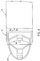
- Figs. 8 and 9 show other possible shapes of optical windows for use as part of seekers/receivers described herein.
- the optical window 210' shown in Fig. 8 has an elongated dome shape, such as that of a prolate ellipsoid.
- the optical window 210" shown in Fig. 9 has a segmented shape, consisting of a plurality of segments 212.
- the segments 212 may have different thicknesses and/or different orientations from adjoining segments, leading them to have different optical properties.
- the segments 212 may be any of a variety of suitable shapes, and the window 210" formed from the segments 212 may have any of variety of suitable overall shapes, such as a variety of generally flat or curved shapes.
- the window 210" may be a monolithic unitary structure, or may include a number of pieces joined together.
- Figs. 10-12 illustrate three possible relative locations of a window, a SAL subsystem, and an IIR subsystem.
- both a SAL subsystem 242 and an IIR subsystem 244 are between a window 246 and a fuselage 248.
- the window 246 may be a single-material window, or alternatively may have different portions, perhaps utilizing different materials, for use by the SAL subsystem 242 and the IIR subsystem 244.
- a SAL subsystem 252 is in front of (outside) a window 256, while an IIR subsystem 254 is between the window 256 and a fuselage 258.
- a SAL subsystem 262 is located within an opening 270 in a window 266.
- An IIR subsystem 264 is between the window 266 and a fuselage 268.
- Fig. 13 shows an alternative embodiment seeker/receiver 300.
- the seeker/receiver 300 is shown with a protective cover 302 in place.
- the cover 302 protects the seeker/receiver 300 from damage, and provides a more aerodynamic shape.
- the cover 302 is removed prior to operation of the seeker/receiver 300, such as by detonation of a squib in order to blow off the cover 302.
- An optics/receiver portion 304 of the seeker/receiver 300 is similar in many respects to those of other embodiments described herein. Many of the parts, and functions, are similar to that of corresponding parts of the seeker/receiver 100 ( Fig. 4 ). One difference is that the window 310 of the seeker/receiver 300 is a multipart window. A small central window or window portion 312 is used for a SAL detector subsystem 314. The central window portion 312 is surrounded by a larger window or window portion 316 for use by an IIR subsystem 318. The window portions 312 and 316 may together make for a substantially smooth surface, with substantially no transition between the window portions 312 and 316 in the form of a shape change.
- the windows 312 may include different respective materials, with each material selected for suitability in use with its corresponding subsystem.
- the central window portion 312 may be made of HIP-treated zinc sulfide or common glass, such as BK7 glass, or even a suitable plastic.
- the surrounding window portion 316 may be made of standard or untreated zinc sulfide. Standard or untreated zinc sulfide is defined herein as zinc sulfide that has not undergone a HIP treatment.
- the surrounding window material alternatively could be treated zinc sulfide, or another material such as treated zinc selenide. It will be appreciated that standard zinc sulfide is less expensive than treated zinc sulfide.
- a tilt mechanism 330 of the seeker/receiver 300 is a spherical gas bearing 332 for precision rotational positioning of an optics/receiver portion 332 of the seeker/receiver 300.
- the optics/receiver portion 332 includes a back bracket 336 having a spherical outer shape. Motors rotate the bracket 336, and thus the rest of the optics/receiver portion 332 as well, within a socket defined by adjoining structure 340 of a fuselage 342.
- the tilt mechanism 330 is a ball-and-socket mechanism, a ball-and-socket gimbal that uses motors to position angle of the optics/receiver portion 332 relative to the fuselage 342.
Landscapes
- Engineering & Computer Science (AREA)
- General Engineering & Computer Science (AREA)
- Chemical & Material Sciences (AREA)
- Combustion & Propulsion (AREA)
- Physics & Mathematics (AREA)
- Electromagnetism (AREA)
- Aviation & Aerospace Engineering (AREA)
- Aiming, Guidance, Guns With A Light Source, Armor, Camouflage, And Targets (AREA)
Description
- The application is in the field for seekers in moving bodies for target acquisition and for guidance of the bodies.
- Seekers have long been used in munitions such as missiles in order to acquire targets, and for other guidance procedures. Multiple mode seekers, which acquire data using multiple wavelengths of energy, have also been used. Such sensors respond to both infrared and microwave radiation, for instance. Such seekers have been generally located at the nose of aircraft or missiles, in order to obtain an unobstructed field of view. Seekers have generally been placed within a window at the nose of the vehicle.
-
US 4240569 discusses a movable radome for the front end of a missile or the like, comprising a generally dome or spherical shaped articulated housing, with an infra-red window surrounded by a dielectric window so that both infra-red and radar sending and sensing units may be mounted within the dome. -
US 7183966 discusses a target sensing apparatus having a seeker dome, an optics system within the seeker dome, a first detector which receives microwave energy, of a first frequency, via an aperture defined by the dome, and a second detector which images a target by light wave energy of second and third frequencies via the optics system. - Improvements over prior seekers would in general be desirable.
- Unlike prior seekers, which have utilized a fixed window with detectors and optics within the window able to tilt relative to the window, seekers are described herein in which the forward window, detectors, and optics all tilt as a unit. The prior fixed-window systems limit the practical window shapes, due to a need to present substantially similar properties to the detectors and optics regardless of angle of tilt. This not only limits available shapes, but as a practical matter requires the fixed window to be made of the same material throughout. Further, the present fixed-window configurations limit the available locations for placement of the detectors and optics, in order to obtain performance that was largely invariant to tilting of the detectors and optics.
- A multimode seeker according to claim 1 is presented, comprising an optics/receiver portion that tilts as a unit. The optics/receiver portion includes an optical window that is part of an outside surface of the moving body that the seeker is part of
- According to another aspect of the invention, an optical window for a seeker has a shape that is not a portion of a sphere. The shape may be flat, an ellipsoid, a segmented shape, or other non-spherical shapes.
- According to yet another aspect of the invention, an optical window for a multiple frequency seeker has different materials and/or different optical properties in different portions.
- According to a further aspect of the invention, a multimode seeker for a moving body includes: a laser energy receiver for detecting incoming laser energy; an imaging infrared (IIR) receiver for detecting incoming infrared energy; an optical window through which at least the infrared energy passes before reaching the IIR receiver; and a tilt mechanism for tilting the laser energy receiver, the IIR receiver, and the optical window, as a unit, relative to other parts of the moving body.
- According to a still further aspect of the invention, a multimode seeker for a moving body includes: a pair of receivers that preferentially detect different wavelengths of energy; an optical window through which incoming energy passes from outside of the moving body to at least one of the receivers; and a tilt mechanism for tilting the receivers and the window, as a unit, relative to other parts of the moving body.
- According to another aspect of the invention, a method of operating a seeker of a moving body includes: using a tilt mechanism of the seeker to tilt as a unit a portion of the seeker, relative to the moving body, during flight of the moving body. The portion includes: a window at an external surface of the moving body; a detector for detecting incoming energy that passes through the window from outside the moving body; and optics that directs and focuses the incoming energy to the detector.
- To the accomplishment of the foregoing and related ends, the invention comprises the features hereinafter fully described and particularly pointed out in the claims. The following description and the annexed drawings set forth in detail certain illustrative embodiments of the invention. These embodiments are indicative, however, of but a few of the various ways in which the principles of the invention may be employed. Other objects, advantages and novel features of the invention will become apparent from the following detailed description of the invention when considered in conjunction with the drawings.
- In the annexed drawings, which are not necessarily to scale:
-
Fig. 1 is a cross-sectional view of a moving body with a seeker/receiver system in accordance with an embodiment of the invention; -
Fig. 2 is a schematic diagram of a prior art seeker/receiver system; -
Fig. 3 is a schematic diagram of parts of a seeker/receiver system in accordance with an embodiment of the invention; -
Fig. 4 is an oblique, partial cutaway view of a seeker/receiver in accordance with another embodiment of the present invention; -
Fig. 5 is an oblique view showing the tilt mechanism of the seeker/receiver ofFig. 4 ; -
Fig. 6 is an exploded view of the tilt mechanism ofFig. 5 ; -
Fig. 7 is an oblique view of a seeker/receiver system having a substantially flat window, in accordance with yet another embodiment of the present invention; -
Fig. 8 is a cross-sectional view of an elongate-shape window usable as part of a seeker/receiver system, in accordance with still another embodiment of the present invention; -
Fig. 9 is a cross-sectional view of a segmented window usable as part of a seeker/receiver system, in accordance with still another embodiment of the present invention; -
Fig. 10 is a schematic view showing a first general arrangement of parts a seeker/receiver system, in accordance with a further embodiment of the invention; -
Fig. 11 is a schematic view showing a second general arrangement of parts a seeker/receiver system, in accordance with a still further embodiment of the invention; -
Fig. 12 is a schematic view showing a third general arrangement of parts a seeker/receiver system, in accordance with another embodiment of the invention; and -
Fig. 13 is sectional view of a seeker/receiver system in accordance with yet another embodiment of the invention. - A seeker/receiver system for a moving body, such as for guiding the moving body to a target, includes an optics/receiver portion that tilts as a unit relative to other parts of the moving body. The optics/receiver portion includes a window which may be used to enclose and protect one or both of a pair of receivers or detectors, such as a laser energy detector or receiver, and an infrared energy detector or receiver. By moving the window and the receivers as a unit a set positional relationship is maintained between all of the elements of the optics/receiver portion. This simplifies the optics by obviating the need for all aspects of the window to present the same properties to energy detectors that tilt relative to it. This allows for different shapes for the window, for different materials to be used for different parts of window (for example materials selected for desirable optical properties in conjunction with the different energy detectors), and/or for placement of one of the detectors outside of the window for another of the detectors. The optics/receiver portion may be tilted using a tilt mechanism such as a gimbal.
- Referring initially to
Fig. 1 , a portion of a movingbody 10 is shown. The movingbody 10 may be any of a variety of targeted air vehicles, such as a missile, a projectile, or other type of munition. The movingbody 10 has a targeting system such as a seeker/receiver 14 for acquiring and tracking targets. The seeker/receiver 14 works in general by mostly passively receiving signals bouncing off of a target. The seeker/receiver 14 includes an optics /receiver portion 16, and atilt system 20. The optics/receiver portion 16 includes a semi-active laser (SAL) receiver orsubsystem 24 and an imaging infrared (IIR) receiver orsubsystem 26. The SAL receiver may be used for detecting energy having a 1.064 µm (micron) wavelength (or energy of another suitable wavelength), to give one example frequency. TheIIR receiver 26 may be configured for detecting energy having an 8-13 micron wavelength energy (or energy of another suitable wavelength). - The optics/
receiver portion 16 also includes anoptical window 30 through which one or both of theSAL receiver 24 and theIIR receiver 26 receive signals. Thetilt system 20 is used to tilt the optics/receiver portion 16, as a unit, relative to other parts of afuselage 34 of themoving body 10. A usual configuration is for the seeker/receiver 14 to be placed at the front of the movingbody 10. This is the location where the seeker/receiver is able to get the best view of potential targets, and is thus able to be most effective. - The ability of the optics/
receiver portion 16 to tilt or otherwise move as a unit allows for improvements in configuration of the seeker/receiver 14. A wider range of configurations for thereceivers window 30 may be utilized. Additional other variations in configuration of the optics/receiver portion 16 may be made as a result of theportion 16 being able to tilt as a unit. Some of these variations are described below with regard to certain exemplary embodiments. However it will be appreciated that additional variations are possible. -
Figs. 2 and 3 illustrate a difference between a prior art seeker/receiver and a system such as that shown inFig. 1 . The prior art seeker/receiver 40 inFig. 2 has a fixedwindow 42, with an IIR detector 44 (and its associated optics) tiltable within the fixedwindow 42. Two positions of theIIR detector 44 are shown inFig. 2 -- one in solid lines, and the other in broken lines. This configuration results in many limitations: 1) thewindow 42 has to be large enough to cover a full field of regard for the seeker/receiver 40; 2) thewindow 42 must be shaped so that it is able to provide substantially similar optical properties throughout the field of regard, no matter what the tilt of theIIR detector 44 is; and 3) there is a limit as to the permissible location of theIIR detector 44 so that it is a focal point or other suitable location within the fixedwindow 42. - In addition, further difficulties present themselves for seeker/receivers that also include a SAL detector. In such systems the SAL detector needs to tilt as well, necessitating its placement inside the fixed
window 42. The SAL detector thus must image through the same fixedwindow 42 used by theIIR detector 44. This may result in the material for the fixedwindow 42 being a compromise between a material optimized for use with the SAL detector, or a material optimized for use with theIIR detector 44. Or a more expensive material, suitable for both detectors, may have to be used for the entire fixedwindow 42. Further, the position of the SAL detector relative to the fixedwindow 42 may be seriously constrained by the need to have substantially constant optical characteristics for the SAL detector as the SAL detector is tilted or rotated. -
Fig. 3 schematically shows a seeker/receiver 60 that may be provided to overcome these difficulties. The seeker/receiver 60 has awindow 62 that tilts or rotates along with an IIR detector 64 (and other optics associated with IIR detector). Thewindow 62 and theIIR detector 64 together constitute an optics/receiver portion 66 of the seeker/receiver 60, with the optics/receiver portion 66 tilting as a unit. Two positions of the optics/receiver portion 66 are shown inFig. 3 -- one in solid lines, and the other in broken lines. By having the optics/receiver portion 66 tilt as a unit there is no need for thewindow 62 to have a shape that can provide substantially similar optical properties for a range of relative positions or orientations between theIIR detector 64 and thewindow 62. This is because the seeker/receiver 60 has a fixed relative position/orientation between thewindow 62 and theIIR detector 64, with thewindow 62 and theIIR detector 64 only tilting as a combined unit. This configuration allows different shapes to be utilized for thewindow 62, such as the flat shape shown inFig. 3 . In addition thewindow 62 may be faceted or segmented, with different facets or segments providing different optical characteristics. - A further advantage to tilting the optics/
receiver portion 66 as a unit is that correction may be made at theIIR detector 64 for variations in optical properties in different parts of thewindow 62. Since there is a fixed spatial relationship between theIIR detector 64 and thewindow 62 only one set of corrections or adjustments would be necessary. - A still further advantage is that having a movable window may enable use of smaller window. This may result in a less expensive and lighter seeker.
- Other advantages may be realized when the seeker/
receiver 60 is a multifrequency seeker (also referred to as a multimode seeker), for example including a SAL detector. The SAL detector would be a part of the optics/receiver portion 66, tiltable along with thewindow 62 and theIIR detector 64. The SAL detector may be placed in any of a variety of locations, inside thewindow 62, outside of thewindow 62, or even in an opening in thewindow 62, for example in an opening at the center of thewindow 62, along a central axis of the seeker/receiver 60. Thewindow 62 may have different portions optimized for the different wavelengths used by the SAL detector and theIIR detector 64, for example utilizing different materials, and/or materials with different treatments to obtain different properties. One or both of the materials may be a relatively low cost material. -
Fig. 4 shows one embodiment, a seeker/receiver 100 that with has an optics/receiver portion 102 that is tiltable by a tilt system ormechanism 104. The optics/receiver portion 102 includes awindow 110, anIIR detector 112, and aSAL detector 114. - The
SAL detector 114 is mounted to an outside surface of thewindow 110. TheSAL detector 114 is part of a SAL subsystem orreceiver 120 that also includes aSAL filter 122 and aSAL lens 124. A suitable SAL detector may be obtained from PerkinElmer, Inc., of Freemont, California, USA. Energy is focused on theSAL detector 114 by thelens 124, after first passing though theSAL filter 122. TheSAL filter 122 insures that most of the solar radiation does not reach theSAL detector 114. Thelens 124 may be made of a material, such as zinc sulfide or zinc selenide. More broadly, thelens 124 may be made of any material that substantially passes the 1.064 µm radiation (or other radiation), another example of a material being polyetherimide. - The
window 110 is shown having a dome shape, for example a portion or section of a sphere. Alternatively thewindow 110 may have a wide variety of other alternative shapes, some of which are discussed below in connection with other embodiments. Thewindow 110 may be hot isostatic pressed (HIP) zinc sulfide, such as a material sold under the trademark CLEARTRAN. Such HIP-treated zinc sulfide is a multispectral chemical vapor deposited ZnS. The HIP treatment removes water, improves transmission in the near IR and visible spectrum region, by altering the chemical and crystalline structure of the ZnS, among other improvements in properties. - The
IIR detector 112 is part of anIIR subsystem receiver 130. TheIIR subsystem 130 also includes anIIR mirror 134, a central IIR reflector (which also could be referred to as a beam splitter or a dichroic mirror), and an IIR lens. Incoming IIR energy passes through outer portions of thedome window 110 and is reflected off of theIIR mirror 134 toward the central reflector. At the central reflector the incoming IIR energy is reflected again, toward theIIR detector 112. The IIR lens focuses this energy onto theIIR detector 112. - The
mirror 134 may be made of aluminum or another suitable material or coating for reflecting IR energy. The central reflector may be made of SiO2 or another suitable material. The lens may be made of germanium or another suitable material. - Parts of the optics for the
IIR subsystem 130 may be also be used by amicrowave antenna 150 that transmits millimeter wave (MMW) energy. MMW energy transmitted by theantenna 150 passes through the central reflector and is reflected by themirror 134. The reflected MMW energy passes out through thewindow 110, out of the seeker/receiver 100. - With reference now in addition to
Figs. 5 and6 , details will be given regarding the parts and operation of the tilt system ormechanism 104. Thetilt mechanism 104 includes a base orpedestal 160 that is fixed to the fuselage of the munition or other moving body. Anouter gimbal ring 162 is pivotally coupled to the base orpedestal 160. Thebase 160 and theouter gimbal ring 162 are coupled together at respective sets ofholes parts elevation motor 170 is used to tilt theouter gimbal ring 162 relative to the base 160 (changing the elevation of the outer gimbal ring 162). Theelevation motor 170 is inserted through one of theholes 164 of thebase 160, and has ashaft 172 that engages acorresponding hole 166 in theouter gimbal ring 162. On the opposite side of thebase 160 and theouter gimbal ring 162, anelevation position sensor 174 provides feedback on the position (orientation) of theouter gimbal ring 162 relative to that of thebase 160. Theelevation motor 170 and theelevation position sensor 174 are attached to opposite sides of thebase 160, for example by use ofscrews 176. Theelevation motor 170 may be controlled by a suitable controller for the seeker/receiver 100 (Fig. 4 ), which may use data from theelevation position sensor 174 as an input. - An
inner gimbal ring 182 is pivotally mounted to theouter gimbal ring 162, to allow theinner gimbal ring 182 to tilt relative to theouter gimbal ring 162. The gimbal rings 162 and 182 are coupled together at respective sets ofholes azimuth motor 190 is attached to theouter gimbal ring 162. Ashaft 192 of themotor 190 protrudes through one of theholes 184, and is coupled to theinner gimbal ring 182 at a corresponding one of theholes 186. Theazimuth motor 190 is used to tilt or pivot theinner gimbal ring 182 relative to theouter gimbal ring 162. Anazimuth position sensor 194 is coupled to the opposite end of the gimbal rings 162 and 182. Theazimuth position sensor 194 is used to measure the azimuth position of theinner gimbal ring 182. Theazimuth motor 190 may be controlled in a manner similar to that of theelevation motor 170. Theazimuth position sensor 194 may have its data utilized in a manner similar to that of theelevation position sensor 174. Theazimuth motor 190 and theazimuth position sensor 194 are attached to opposite sides of theouter gimbal ring 162, such as by use ofscrews 196. - The optics/receiver portion 102 (
Fig. 4 ) is attached to theinner gimbal ring 182 at a series ofbrackets 198 along theinner gimbal ring 182. Threaded fasteners (not shown) may be used to couple the optics/receiver portion to theinner gimbal ring 182. - The
seeker 100 is thus tiltable in a pair of orthogonal directions, in elevation and azimuth. It will be appreciated that configuration shown inFigs. 4-6 is only one of many possible configurations for a seeker/receiver. Many variations are possible including for example different shapes and/or control mechanisms for the gimbal rings 162 and 182. -
Fig. 7 shows an alternative embodiment seeker/receiver 200 that differs from the seeker/receiver 100 (Fig. 4 ) in that the seeker/receiver 100 has a flatoptical window 210, as opposed to the dome-shaped optical window 110 (Fig. 4 ) of the seeker/receiver 100. -
Figs. 8 and9 show other possible shapes of optical windows for use as part of seekers/receivers described herein. The optical window 210' shown inFig. 8 has an elongated dome shape, such as that of a prolate ellipsoid. - The
optical window 210" shown inFig. 9 has a segmented shape, consisting of a plurality ofsegments 212. Thesegments 212 may have different thicknesses and/or different orientations from adjoining segments, leading them to have different optical properties. Thesegments 212 may be any of a variety of suitable shapes, and thewindow 210" formed from thesegments 212 may have any of variety of suitable overall shapes, such as a variety of generally flat or curved shapes. Thewindow 210" may be a monolithic unitary structure, or may include a number of pieces joined together. -
Figs. 10-12 illustrate three possible relative locations of a window, a SAL subsystem, and an IIR subsystem. In the seeker/receiver 240 shown inFig. 10 , both aSAL subsystem 242 and anIIR subsystem 244 are between awindow 246 and afuselage 248. Thewindow 246 may be a single-material window, or alternatively may have different portions, perhaps utilizing different materials, for use by theSAL subsystem 242 and theIIR subsystem 244. In the seeker/receiver 250 shown inFig. 11 , aSAL subsystem 252 is in front of (outside) awindow 256, while anIIR subsystem 254 is between thewindow 256 and afuselage 258. In the seeker/receiver 260 shown inFig. 12 , aSAL subsystem 262 is located within anopening 270 in awindow 266. AnIIR subsystem 264 is between thewindow 266 and afuselage 268. - It will be appreciated that any of the configurations shown in
Figs. 10-12 may be combined with appropriate features of other embodiments described herein. More generally, features of the various embodiments described herein may be combined with one another as appropriate. -
Fig. 13 shows an alternative embodiment seeker/receiver 300. The seeker/receiver 300 is shown with aprotective cover 302 in place. Thecover 302 protects the seeker/receiver 300 from damage, and provides a more aerodynamic shape. Thecover 302 is removed prior to operation of the seeker/receiver 300, such as by detonation of a squib in order to blow off thecover 302. - An optics/
receiver portion 304 of the seeker/receiver 300 is similar in many respects to those of other embodiments described herein. Many of the parts, and functions, are similar to that of corresponding parts of the seeker/receiver 100 (Fig. 4 ). One difference is that thewindow 310 of the seeker/receiver 300 is a multipart window. A small central window orwindow portion 312 is used for aSAL detector subsystem 314. Thecentral window portion 312 is surrounded by a larger window orwindow portion 316 for use by anIIR subsystem 318. Thewindow portions window portions windows 312 may include different respective materials, with each material selected for suitability in use with its corresponding subsystem. For example, thecentral window portion 312 may be made of HIP-treated zinc sulfide or common glass, such as BK7 glass, or even a suitable plastic. The surroundingwindow portion 316 may be made of standard or untreated zinc sulfide. Standard or untreated zinc sulfide is defined herein as zinc sulfide that has not undergone a HIP treatment. The surrounding window material alternatively could be treated zinc sulfide, or another material such as treated zinc selenide. It will be appreciated that standard zinc sulfide is less expensive than treated zinc sulfide. - A
tilt mechanism 330 of the seeker/receiver 300 is a spherical gas bearing 332 for precision rotational positioning of an optics/receiver portion 332 of the seeker/receiver 300. The optics/receiver portion 332 includes aback bracket 336 having a spherical outer shape. Motors rotate thebracket 336, and thus the rest of the optics/receiver portion 332 as well, within a socket defined by adjoiningstructure 340 of afuselage 342. Thus thetilt mechanism 330 is a ball-and-socket mechanism, a ball-and-socket gimbal that uses motors to position angle of the optics/receiver portion 332 relative to thefuselage 342. - Although the invention has been shown and described with respect to a certain preferred embodiment or embodiments, it is obvious that equivalent alterations and modifications will occur to others skilled in the art upon the reading and understanding of this specification and the annexed drawings. In particular regard to the various functions performed by the above described elements (components, assemblies, devices, compositions, etc.), the terms (including a reference to a "means") used to describe such elements are intended to correspond, unless otherwise indicated, to any element which performs the specified function of the described element (i.e., that is functionally equivalent), even though not structurally equivalent to the disclosed structure which performs the function in the herein illustrated exemplary embodiment or embodiments of the invention. In addition, while a particular feature of the invention may have been described above with respect to only one or more of several illustrated embodiments, such feature may be combined with one or more other features of the other embodiments, as may be desired and advantageous for any given or particular application.
Claims (15)
- A multimode seeker (14) for a moving body (10), the seeker comprising:a laser energy receiver (24) for detecting incoming laser energy, wherein the receiver comprises a lens (124);an imaging infrared, IIR, receiver (26) for detecting incoming infrared energy at a different wavelength from the incoming laser energy;an optical window (30) through which at least the infrared energy passes before reaching the IIR receiver (26), wherein the IIR receiver (26) is between the window (30) and a fuselage (34) of the moving body (10); anda tilt mechanism (20) for tilting the laser energy receiver (24), the IIR receiver (26), and the optical window (30), as a unit, relative to other parts of the moving body (10);wherein the laser energy receiver (24) is mechanically coupled to the window (30); andwherein at least the lens (124) of the laser energy receiver (24) is not between the window (30) and the fuselage (34) of the moving body (10).
- The multimode seeker of claim 1, wherein the optical window (30) has multiple parts that preferentially pass different energy frequencies.
- The multimode seeker of claim 2,
wherein a first part of the optical window (30) is operatively coupled to the laser energy receiver (24) for passing energy therethrough to be received by the laser energy receiver (24); and
wherein a second part of the optical window (30) is operatively coupled to the infrared energy receiver for passing energy therethrough to be received by the IIR receiver (26). - The multimode seeker of claim 3, wherein the parts of the window (30) are made of different materials.
- The multimode seeker of claim 4, wherein one of the materials is standard zinc sulfide.
- The multimode seeker of any of claims 3 to 5, further comprising a microwave antenna (150) that transmits millimeter wave, MMW, energy that passes through the second part of the optical window (30).
- The multimode seeker of any of claims 1 to 6, wherein the laser energy receiver (252) is mechanically coupled to an outside surface of the window (256), in front of the window (30).
- The multimode seeker of any of claims 1 to 6, wherein the laser energy receiver (262) passes through an opening (270) around a central axis of the window (266).
- The multimode seeker of any of claims 1 to 6, wherein the window (110) has a substantially spherical shape.
- The multimode seeker of any of claims 1 to 6, wherein the window (210) is substantially flat.
- The multimode seeker of any of claims 1 to 6, wherein the window (210') has an ellipsoid shape.
- The multimode seeker of any of claims 1, 2, or 7 to 11, wherein at least part of the window is made of standard zinc sulfide.
- The multimode seeker of any of claims 1, 2, or 7 to 11, wherein at least part of the window is made of standard zinc selenide.
- The multimode seeker of any of claims 1 to 13, wherein the tilt mechanism (20) includes a gimbal (182) that the laser energy receiver, the IIR receiver, and the optical window are all mechanically coupled to.
- The multimode seeker of any of claims 1 to 14, wherein the tilt mechanism (20) tilts in at least two orthogonal directions.
Applications Claiming Priority (2)
| Application Number | Priority Date | Filing Date | Title |
|---|---|---|---|
| US12/478,005 US8259291B2 (en) | 2009-06-04 | 2009-06-04 | Multi-band seeker with tiltable optical/receiver portion |
| PCT/US2010/026471 WO2010141136A1 (en) | 2009-06-04 | 2010-03-08 | Multi-band seeker with tiltable optical/receiver portion |
Publications (2)
| Publication Number | Publication Date |
|---|---|
| EP2438385A1 EP2438385A1 (en) | 2012-04-11 |
| EP2438385B1 true EP2438385B1 (en) | 2017-11-01 |
Family
ID=42244973
Family Applications (1)
| Application Number | Title | Priority Date | Filing Date |
|---|---|---|---|
| EP10709939.2A Active EP2438385B1 (en) | 2009-06-04 | 2010-03-08 | Multi-band seeker with tiltable optical receiver portion |
Country Status (3)
| Country | Link |
|---|---|
| US (1) | US8259291B2 (en) |
| EP (1) | EP2438385B1 (en) |
| WO (1) | WO2010141136A1 (en) |
Families Citing this family (11)
| Publication number | Priority date | Publication date | Assignee | Title |
|---|---|---|---|---|
| DE102011117923A1 (en) * | 2011-11-09 | 2013-05-16 | Diehl Bgt Defence Gmbh & Co. Kg | Seeker head for a guided missile |
| US8502128B1 (en) * | 2012-09-15 | 2013-08-06 | Raytheon Company | Dual-mode electro-optic sensor and method of using target designation as a guide star for wavefront error estimation |
| US10281551B2 (en) * | 2015-03-30 | 2019-05-07 | Luminit Llc | Compound eye laser tracking device |
| US10890417B2 (en) | 2015-03-30 | 2021-01-12 | Luminit Llc | Compound eye laser tracking device |
| KR101944423B1 (en) * | 2018-03-28 | 2019-01-30 | 엘아이지넥스원 주식회사 | Gimbal Composite Sensor Homming Device and Method |
| KR101953352B1 (en) * | 2018-03-28 | 2019-02-28 | 엘아이지넥스원 주식회사 | Gimbal Composite Sensor Homming System |
| US20200256643A1 (en) * | 2019-02-12 | 2020-08-13 | Bae Systems Information And Electronic Systems Integration Inc. | Projectile guidance system |
| US11619764B2 (en) * | 2020-03-27 | 2023-04-04 | Raytheon Company | High-performance optical surface |
| CN114659407B (en) * | 2020-12-23 | 2023-10-13 | 北京华航无线电测量研究所 | Photoconductive leading-in protective cover connecting component |
| US12405088B2 (en) * | 2023-12-06 | 2025-09-02 | Raytheon Company | Dual-mode roll/nod gimballed seeker for a forming warhead |
| KR102686687B1 (en) * | 2024-05-31 | 2024-07-22 | 국방과학연구소 | Resistance Torque Measurement Device and Method for Direct Drive 2 axis Gimbal |
Family Cites Families (12)
| Publication number | Priority date | Publication date | Assignee | Title |
|---|---|---|---|---|
| US4240596A (en) * | 1978-07-28 | 1980-12-23 | General Dynamics Corporation, Pomona Division | Articulated eyeball radome |
| US4717263A (en) | 1985-07-26 | 1988-01-05 | Compact Spindle Bearing Corporation | Gas bearing |
| GB8713922D0 (en) | 1987-06-15 | 1994-06-22 | Secr Defence | Infra red transparent windows |
| US5973649A (en) | 1997-10-28 | 1999-10-26 | Alliant Techsystems, Inc. | Common aperture dual mode semi-active laser/millimeter wave sensor |
| US6268822B1 (en) | 1999-12-07 | 2001-07-31 | Alenia Marconi Systems Inc. | Dual-frequency millimeter wave and laser radiation receiver |
| US6606066B1 (en) | 2001-10-29 | 2003-08-12 | Northrop Grumman Corporation | Tri-mode seeker |
| US7183966B1 (en) | 2003-04-23 | 2007-02-27 | Lockheed Martin Corporation | Dual mode target sensing apparatus |
| US6924772B2 (en) | 2003-10-30 | 2005-08-02 | Northrop Grumman Corporation | Tri-mode co-boresighted seeker |
| US7185845B1 (en) | 2004-01-16 | 2007-03-06 | Richard Leon Hartman | Faceted ball lens for semi-active laser seeker |
| US7742151B2 (en) | 2005-07-08 | 2010-06-22 | Lockheed Martin Corporation | Laser-based system with LADAR and SAL capabilities |
| US7336345B2 (en) * | 2005-07-08 | 2008-02-26 | Lockheed Martin Corporation | LADAR system with SAL follower |
| DE102007003699B3 (en) | 2007-01-25 | 2008-10-02 | Lfk-Lenkflugkörpersysteme Gmbh | Optical window in an infrared homing head |
-
2009
- 2009-06-04 US US12/478,005 patent/US8259291B2/en active Active
-
2010
- 2010-03-08 EP EP10709939.2A patent/EP2438385B1/en active Active
- 2010-03-08 WO PCT/US2010/026471 patent/WO2010141136A1/en not_active Ceased
Non-Patent Citations (1)
| Title |
|---|
| None * |
Also Published As
| Publication number | Publication date |
|---|---|
| EP2438385A1 (en) | 2012-04-11 |
| US20120062410A1 (en) | 2012-03-15 |
| US8259291B2 (en) | 2012-09-04 |
| WO2010141136A1 (en) | 2010-12-09 |
Similar Documents
| Publication | Publication Date | Title |
|---|---|---|
| US8259291B2 (en) | Multi-band seeker with tiltable optical/receiver portion | |
| US8497457B2 (en) | Flight vehicles with improved pointing devices for optical systems | |
| US8982210B2 (en) | Vehicle having scanning imager with fixed camera and multiple achromatic prism pairs | |
| EP2488888B1 (en) | Off-axis reflective transmit telescope for a directed infrared countermeasures (dircm) system | |
| US6057915A (en) | Projectile tracking system | |
| US7813644B2 (en) | Optical device with a steerable light path | |
| US20090260511A1 (en) | Target acquisition and tracking system | |
| US8575527B2 (en) | Vehicle having side portholes and an array of fixed EO imaging sub-systems utilizing the portholes | |
| US9976837B2 (en) | Seeker head and air vehicle including same | |
| US20060283317A1 (en) | Missile protection system for vehicles | |
| EP2989410B1 (en) | Multimode shared aperture seeker | |
| US6028712A (en) | Optical system and method for providing corrected optical images | |
| EP0233080B1 (en) | Infrared seeker | |
| EP1322903B1 (en) | Dual-frequency millimeter wave and laser radiation receiver | |
| US5681009A (en) | Missile having endoatmospheric and exoatmospheric seeker capability | |
| EP2622304B1 (en) | Seeker with a molded dichroic mirror | |
| US6484619B1 (en) | Observation or sighting system | |
| US6552318B1 (en) | Sensor system with rigid-body error correcting element | |
| KR102226255B1 (en) | directional energy weapon system | |
| US12061334B2 (en) | Optical scanning system using micro-electro-mechanical system (mems) micro-mirror arrays (MMAs) | |
| KR101968330B1 (en) | Homing apparatus with multiple sensor | |
| IL148452A (en) | Method and device for prevention of gimbal-locking | |
| Fan et al. | Analysis of the development of missile-borne IR imaging detecting technologies | |
| Daugherty et al. | High-speed multiple object passive and active electro-optical tracking |
Legal Events
| Date | Code | Title | Description |
|---|---|---|---|
| PUAI | Public reference made under article 153(3) epc to a published international application that has entered the european phase |
Free format text: ORIGINAL CODE: 0009012 |
|
| 17P | Request for examination filed |
Effective date: 20111221 |
|
| AK | Designated contracting states |
Kind code of ref document: A1 Designated state(s): AT BE BG CH CY CZ DE DK EE ES FI FR GB GR HR HU IE IS IT LI LT LU LV MC MK MT NL NO PL PT RO SE SI SK SM TR |
|
| DAX | Request for extension of the european patent (deleted) | ||
| STAA | Information on the status of an ep patent application or granted ep patent |
Free format text: STATUS: EXAMINATION IS IN PROGRESS |
|
| 17Q | First examination report despatched |
Effective date: 20161115 |
|
| REG | Reference to a national code |
Ref country code: DE Ref legal event code: R079 Ref document number: 602010046353 Country of ref document: DE Free format text: PREVIOUS MAIN CLASS: F41G0007000000 Ipc: F42B0015010000 |
|
| GRAP | Despatch of communication of intention to grant a patent |
Free format text: ORIGINAL CODE: EPIDOSNIGR1 |
|
| STAA | Information on the status of an ep patent application or granted ep patent |
Free format text: STATUS: GRANT OF PATENT IS INTENDED |
|
| RIC1 | Information provided on ipc code assigned before grant |
Ipc: F41G 7/00 20060101ALI20170428BHEP Ipc: F41G 7/22 20060101ALI20170428BHEP Ipc: F42B 15/01 20060101AFI20170428BHEP |
|
| INTG | Intention to grant announced |
Effective date: 20170530 |
|
| GRAS | Grant fee paid |
Free format text: ORIGINAL CODE: EPIDOSNIGR3 |
|
| GRAA | (expected) grant |
Free format text: ORIGINAL CODE: 0009210 |
|
| STAA | Information on the status of an ep patent application or granted ep patent |
Free format text: STATUS: THE PATENT HAS BEEN GRANTED |
|
| AK | Designated contracting states |
Kind code of ref document: B1 Designated state(s): AT BE BG CH CY CZ DE DK EE ES FI FR GB GR HR HU IE IS IT LI LT LU LV MC MK MT NL NO PL PT RO SE SI SK SM TR |
|
| REG | Reference to a national code |
Ref country code: GB Ref legal event code: FG4D |
|
| REG | Reference to a national code |
Ref country code: CH Ref legal event code: EP Ref country code: AT Ref legal event code: REF Ref document number: 942471 Country of ref document: AT Kind code of ref document: T Effective date: 20171115 |
|
| REG | Reference to a national code |
Ref country code: IE Ref legal event code: FG4D |
|
| REG | Reference to a national code |
Ref country code: DE Ref legal event code: R096 Ref document number: 602010046353 Country of ref document: DE |
|
| REG | Reference to a national code |
Ref country code: FR Ref legal event code: PLFP Year of fee payment: 9 |
|
| REG | Reference to a national code |
Ref country code: NL Ref legal event code: MP Effective date: 20171101 |
|
| REG | Reference to a national code |
Ref country code: LT Ref legal event code: MG4D |
|
| REG | Reference to a national code |
Ref country code: AT Ref legal event code: MK05 Ref document number: 942471 Country of ref document: AT Kind code of ref document: T Effective date: 20171101 |
|
| PG25 | Lapsed in a contracting state [announced via postgrant information from national office to epo] |
Ref country code: SE Free format text: LAPSE BECAUSE OF FAILURE TO SUBMIT A TRANSLATION OF THE DESCRIPTION OR TO PAY THE FEE WITHIN THE PRESCRIBED TIME-LIMIT Effective date: 20171101 Ref country code: ES Free format text: LAPSE BECAUSE OF FAILURE TO SUBMIT A TRANSLATION OF THE DESCRIPTION OR TO PAY THE FEE WITHIN THE PRESCRIBED TIME-LIMIT Effective date: 20171101 Ref country code: NL Free format text: LAPSE BECAUSE OF FAILURE TO SUBMIT A TRANSLATION OF THE DESCRIPTION OR TO PAY THE FEE WITHIN THE PRESCRIBED TIME-LIMIT Effective date: 20171101 Ref country code: FI Free format text: LAPSE BECAUSE OF FAILURE TO SUBMIT A TRANSLATION OF THE DESCRIPTION OR TO PAY THE FEE WITHIN THE PRESCRIBED TIME-LIMIT Effective date: 20171101 Ref country code: LT Free format text: LAPSE BECAUSE OF FAILURE TO SUBMIT A TRANSLATION OF THE DESCRIPTION OR TO PAY THE FEE WITHIN THE PRESCRIBED TIME-LIMIT Effective date: 20171101 Ref country code: NO Free format text: LAPSE BECAUSE OF FAILURE TO SUBMIT A TRANSLATION OF THE DESCRIPTION OR TO PAY THE FEE WITHIN THE PRESCRIBED TIME-LIMIT Effective date: 20180201 |
|
| PG25 | Lapsed in a contracting state [announced via postgrant information from national office to epo] |
Ref country code: BG Free format text: LAPSE BECAUSE OF FAILURE TO SUBMIT A TRANSLATION OF THE DESCRIPTION OR TO PAY THE FEE WITHIN THE PRESCRIBED TIME-LIMIT Effective date: 20180201 Ref country code: GR Free format text: LAPSE BECAUSE OF FAILURE TO SUBMIT A TRANSLATION OF THE DESCRIPTION OR TO PAY THE FEE WITHIN THE PRESCRIBED TIME-LIMIT Effective date: 20180202 Ref country code: AT Free format text: LAPSE BECAUSE OF FAILURE TO SUBMIT A TRANSLATION OF THE DESCRIPTION OR TO PAY THE FEE WITHIN THE PRESCRIBED TIME-LIMIT Effective date: 20171101 Ref country code: LV Free format text: LAPSE BECAUSE OF FAILURE TO SUBMIT A TRANSLATION OF THE DESCRIPTION OR TO PAY THE FEE WITHIN THE PRESCRIBED TIME-LIMIT Effective date: 20171101 Ref country code: HR Free format text: LAPSE BECAUSE OF FAILURE TO SUBMIT A TRANSLATION OF THE DESCRIPTION OR TO PAY THE FEE WITHIN THE PRESCRIBED TIME-LIMIT Effective date: 20171101 Ref country code: IS Free format text: LAPSE BECAUSE OF FAILURE TO SUBMIT A TRANSLATION OF THE DESCRIPTION OR TO PAY THE FEE WITHIN THE PRESCRIBED TIME-LIMIT Effective date: 20180301 |
|
| PG25 | Lapsed in a contracting state [announced via postgrant information from national office to epo] |
Ref country code: CZ Free format text: LAPSE BECAUSE OF FAILURE TO SUBMIT A TRANSLATION OF THE DESCRIPTION OR TO PAY THE FEE WITHIN THE PRESCRIBED TIME-LIMIT Effective date: 20171101 Ref country code: SK Free format text: LAPSE BECAUSE OF FAILURE TO SUBMIT A TRANSLATION OF THE DESCRIPTION OR TO PAY THE FEE WITHIN THE PRESCRIBED TIME-LIMIT Effective date: 20171101 Ref country code: EE Free format text: LAPSE BECAUSE OF FAILURE TO SUBMIT A TRANSLATION OF THE DESCRIPTION OR TO PAY THE FEE WITHIN THE PRESCRIBED TIME-LIMIT Effective date: 20171101 Ref country code: DK Free format text: LAPSE BECAUSE OF FAILURE TO SUBMIT A TRANSLATION OF THE DESCRIPTION OR TO PAY THE FEE WITHIN THE PRESCRIBED TIME-LIMIT Effective date: 20171101 Ref country code: CY Free format text: LAPSE BECAUSE OF FAILURE TO SUBMIT A TRANSLATION OF THE DESCRIPTION OR TO PAY THE FEE WITHIN THE PRESCRIBED TIME-LIMIT Effective date: 20171101 |
|
| REG | Reference to a national code |
Ref country code: DE Ref legal event code: R097 Ref document number: 602010046353 Country of ref document: DE |
|
| PG25 | Lapsed in a contracting state [announced via postgrant information from national office to epo] |
Ref country code: RO Free format text: LAPSE BECAUSE OF FAILURE TO SUBMIT A TRANSLATION OF THE DESCRIPTION OR TO PAY THE FEE WITHIN THE PRESCRIBED TIME-LIMIT Effective date: 20171101 Ref country code: SM Free format text: LAPSE BECAUSE OF FAILURE TO SUBMIT A TRANSLATION OF THE DESCRIPTION OR TO PAY THE FEE WITHIN THE PRESCRIBED TIME-LIMIT Effective date: 20171101 Ref country code: IT Free format text: LAPSE BECAUSE OF FAILURE TO SUBMIT A TRANSLATION OF THE DESCRIPTION OR TO PAY THE FEE WITHIN THE PRESCRIBED TIME-LIMIT Effective date: 20171101 Ref country code: PL Free format text: LAPSE BECAUSE OF FAILURE TO SUBMIT A TRANSLATION OF THE DESCRIPTION OR TO PAY THE FEE WITHIN THE PRESCRIBED TIME-LIMIT Effective date: 20171101 |
|
| PLBE | No opposition filed within time limit |
Free format text: ORIGINAL CODE: 0009261 |
|
| STAA | Information on the status of an ep patent application or granted ep patent |
Free format text: STATUS: NO OPPOSITION FILED WITHIN TIME LIMIT |
|
| 26N | No opposition filed |
Effective date: 20180802 |
|
| REG | Reference to a national code |
Ref country code: CH Ref legal event code: PL |
|
| PG25 | Lapsed in a contracting state [announced via postgrant information from national office to epo] |
Ref country code: MC Free format text: LAPSE BECAUSE OF FAILURE TO SUBMIT A TRANSLATION OF THE DESCRIPTION OR TO PAY THE FEE WITHIN THE PRESCRIBED TIME-LIMIT Effective date: 20171101 Ref country code: SI Free format text: LAPSE BECAUSE OF FAILURE TO SUBMIT A TRANSLATION OF THE DESCRIPTION OR TO PAY THE FEE WITHIN THE PRESCRIBED TIME-LIMIT Effective date: 20171101 |
|
| REG | Reference to a national code |
Ref country code: BE Ref legal event code: MM Effective date: 20180331 |
|
| REG | Reference to a national code |
Ref country code: IE Ref legal event code: MM4A |
|
| PG25 | Lapsed in a contracting state [announced via postgrant information from national office to epo] |
Ref country code: LU Free format text: LAPSE BECAUSE OF NON-PAYMENT OF DUE FEES Effective date: 20180308 |
|
| PG25 | Lapsed in a contracting state [announced via postgrant information from national office to epo] |
Ref country code: IE Free format text: LAPSE BECAUSE OF NON-PAYMENT OF DUE FEES Effective date: 20180308 |
|
| PG25 | Lapsed in a contracting state [announced via postgrant information from national office to epo] |
Ref country code: LI Free format text: LAPSE BECAUSE OF NON-PAYMENT OF DUE FEES Effective date: 20180331 Ref country code: BE Free format text: LAPSE BECAUSE OF NON-PAYMENT OF DUE FEES Effective date: 20180331 Ref country code: CH Free format text: LAPSE BECAUSE OF NON-PAYMENT OF DUE FEES Effective date: 20180331 |
|
| PG25 | Lapsed in a contracting state [announced via postgrant information from national office to epo] |
Ref country code: MT Free format text: LAPSE BECAUSE OF NON-PAYMENT OF DUE FEES Effective date: 20180308 |
|
| PG25 | Lapsed in a contracting state [announced via postgrant information from national office to epo] |
Ref country code: PT Free format text: LAPSE BECAUSE OF FAILURE TO SUBMIT A TRANSLATION OF THE DESCRIPTION OR TO PAY THE FEE WITHIN THE PRESCRIBED TIME-LIMIT Effective date: 20171101 Ref country code: HU Free format text: LAPSE BECAUSE OF FAILURE TO SUBMIT A TRANSLATION OF THE DESCRIPTION OR TO PAY THE FEE WITHIN THE PRESCRIBED TIME-LIMIT; INVALID AB INITIO Effective date: 20100308 |
|
| PG25 | Lapsed in a contracting state [announced via postgrant information from national office to epo] |
Ref country code: MK Free format text: LAPSE BECAUSE OF NON-PAYMENT OF DUE FEES Effective date: 20171101 |
|
| P01 | Opt-out of the competence of the unified patent court (upc) registered |
Effective date: 20230530 |
|
| PGFP | Annual fee paid to national office [announced via postgrant information from national office to epo] |
Ref country code: GB Payment date: 20260220 Year of fee payment: 17 |
|
| PGFP | Annual fee paid to national office [announced via postgrant information from national office to epo] |
Ref country code: DE Payment date: 20260219 Year of fee payment: 17 |
|
| PGFP | Annual fee paid to national office [announced via postgrant information from national office to epo] |
Ref country code: FR Payment date: 20260220 Year of fee payment: 17 |
|
| PGFP | Annual fee paid to national office [announced via postgrant information from national office to epo] |
Ref country code: TR Payment date: 20260225 Year of fee payment: 17 |