EP2437522A1 - Hörhilfegerät zur Frequenzkompression - Google Patents
Hörhilfegerät zur Frequenzkompression Download PDFInfo
- Publication number
- EP2437522A1 EP2437522A1 EP11178382A EP11178382A EP2437522A1 EP 2437522 A1 EP2437522 A1 EP 2437522A1 EP 11178382 A EP11178382 A EP 11178382A EP 11178382 A EP11178382 A EP 11178382A EP 2437522 A1 EP2437522 A1 EP 2437522A1
- Authority
- EP
- European Patent Office
- Prior art keywords
- frequency
- frequency band
- signal
- group
- frequency bands
- Prior art date
- Legal status (The legal status is an assumption and is not a legal conclusion. Google has not performed a legal analysis and makes no representation as to the accuracy of the status listed.)
- Granted
Links
Images

Classifications
-
- H—ELECTRICITY
- H04—ELECTRIC COMMUNICATION TECHNIQUE
- H04R—LOUDSPEAKERS, MICROPHONES, GRAMOPHONE PICK-UPS OR LIKE ACOUSTIC ELECTROMECHANICAL TRANSDUCERS; ELECTRIC HEARING AIDS; PUBLIC ADDRESS SYSTEMS
- H04R25/00—Electric hearing aids
- H04R25/35—Electric hearing aids using translation techniques
- H04R25/353—Frequency, e.g. frequency shift or compression
-
- H—ELECTRICITY
- H04—ELECTRIC COMMUNICATION TECHNIQUE
- H04R—LOUDSPEAKERS, MICROPHONES, GRAMOPHONE PICK-UPS OR LIKE ACOUSTIC ELECTROMECHANICAL TRANSDUCERS; ELECTRIC HEARING AIDS; PUBLIC ADDRESS SYSTEMS
- H04R2225/00—Details of deaf aids covered by H04R25/00, not provided for in any of its subgroups
- H04R2225/43—Signal processing in hearing aids to enhance the speech intelligibility
-
- H—ELECTRICITY
- H04—ELECTRIC COMMUNICATION TECHNIQUE
- H04R—LOUDSPEAKERS, MICROPHONES, GRAMOPHONE PICK-UPS OR LIKE ACOUSTIC ELECTROMECHANICAL TRANSDUCERS; ELECTRIC HEARING AIDS; PUBLIC ADDRESS SYSTEMS
- H04R2430/00—Signal processing covered by H04R, not provided for in its groups
- H04R2430/03—Synergistic effects of band splitting and sub-band processing
Definitions
- the invention relates to a hearing aid for performing such a method.
- a frequency-dependent amplification of an incoming input signal to the hearing aid device usually takes place in a hearing aid.
- AGC automatic gain control
- hearing losses in which the hearing loss can not be compensated in a satisfactory manner by a pure frequency-dependent amplification of an acoustic input signal.
- Examples include hearing loss with dead frequency ranges in which spectral components of the acoustic input signal can not be made audible by a high gain.
- a method for adjusting a hearing aid device in which a portion of an input signal spectrum is amplified at a first frequency and shifted to a second frequency as a function of time, on the one hand a high spontaneous acceptance of the hearing system by an almost unadulterated between two adaptation steps sound image of the hearing On the other hand, to support the learning and acclimatization process of the hearing impaired to the new frequency patterns.
- spectral components within a source spectral range are shifted to a target frequency range (typically at lower frequencies).
- the signal components shifted into the target frequency range can be made audible in this frequency range by amplification.
- This object is achieved in a method for frequency compression of the type mentioned above in that a gain of a lying in the selected frequency band signal portion of the input signal or resulting from this signal component signal in response to signal components in non-selected frequency bands of the group of frequency bands.
- the suppressed frequency bands within a group of frequency bands still have some consideration in the target frequency band of the group. If the group of suppressed frequency bands contains a high level of sound energy, this results in a comparatively high amplification for the selected frequency band of the group in the target frequency band. In contrast, in another group of frequency bands in which the suppressed frequency bands have only a small amount of sound energy, the signal transferred from the selected frequency band to the associated target frequency band is correspondingly less amplified or attenuated.
- the invention thus effects a different weighting of the signal components converted into the individual target frequency bands, with the signal components of the input signal in the suppressed frequency bands also being included in this weighting. As a result, sound signals that differ mainly in the suppressed frequency bands can be better distinguished.
- the amplification of the signal component of the input signal in the selected frequency band can take place either before the transfer to the target frequency band or after the transfer, ie after the frequency shift.
- the gain for certain selected frequency bands may also be less than 1, ie an attenuation.
- amplification of a signal component of the input signal or of a signal component resulting from this signal component in the selected frequency band is effected as a function of a signal component of the input signal from at least one non-selected frequency band of the group of frequency bands.
- the signal components of a plurality of non-selected frequency bands preferably the signal components of all non-selected frequency bands, enter into the calculation of the amplification.
- a shape factor F is determined which depends on the spectral content of all frequency bands within a group of frequency bands. The richer the input signal in spectral terms within a particular group of frequency bands, the larger the form factor of that group.
- the form factor acts as an amplification factor, which is applied to the selected frequency band within a group of frequency bands or the respective target frequency band.
- the signal component of the input signal in the selected frequency band or the signal transferred into the relevant target frequency band is multiplied by the form factor.
- a form factor FC is calculated according to the form factor FA, with the difference from FA that at FC the sum of the amounts of the signals of all frequency bands is normalized to the number of frequency bands of the group concerned:
- FC Sum of the Betr ⁇ a ⁇ ⁇ the signals of all frequency b ⁇ a ⁇ ⁇ of a group Number of frequency b ⁇ a ⁇ ⁇ Direction • Amount of the signal of the selected ⁇ a ⁇ ⁇ listen to the frequency band
- the invention is not limited to the calculation methods mentioned by way of example for the form factors FA to FD. Rather, a variety of other ways to determine the form factor is conceivable. In particular, multiplications with constants and / or further variables can be included in the form factors mentioned by way of example. Furthermore, it is possible that - unlike in the above examples - in the respective counter calculation does not always receive the signals of all frequency bands of the respective group. In particular, it is possible that the signal in the respectively selected frequency band is not included in the calculation of the form factor.
- FIG. 1 shows in a highly simplified block diagram by way of example the construction of a hearing aid, in particular a behind the ear portable hearing aid, according to the prior art.
- Hearing devices comprise, in principle, as essential components, an input transducer, an amplifier and an output transducer.
- the input transducer is usually a sound receiver, z. As a microphone, and / or an electromagnetic receiver, for. B. an induction coil.
- the output transducer is usually used as an electroacoustic transducer, z. As miniature speaker or handset, or as an electromechanical transducer, z. B. bone conduction, realized.
- the amplifier is usually integrated in a signal processing unit. In the embodiment according to FIG.
- one or more microphones 2 are installed for receiving the sound from the environment.
- a signal processing unit 3 which is also located in the hearing aid housing 1, processes the microphone signals and amplifies them.
- the output signal of the signal processing unit 3 is transmitted to a loudspeaker or earpiece 4, which outputs an acoustic signal. If necessary, the sound is transmitted to the user's eardrum via a sound tube, which is fixed in the ear canal with an earmold.
- the power supply of the hearing aid and in particular that of the signal processing unit 3 is effected by a battery 5 likewise arranged in the hearing aid housing 1.
- FIG. 2 the division of the transferable from a hearing aid frequency range in a variety of frequency bands can be seen.
- the width of the frequency bands is the same for all frequency bands (eg 200 Hz), but this does not necessarily have to be the case.
- a source frequency range S is generally mapped into a target frequency range D.
- Below a certain limit frequency f c no frequency compression takes place in the exemplary embodiment and above the cutoff frequency f c , a specific number of adjacent frequency bands is combined to form a group of frequency bands. In the exemplary embodiment, this is shown for the groups G1, G2 and G3.
- the number of frequency bands within a group can vary between groups.
- Each group of frequency bands G1, G2, G3 etc is assigned exactly one target frequency band D1, D2, D3 etc.
- a particular frequency band (the "winner frequency band") is selected, eg the frequency band in which the signal component of the input signal has the highest signal level compared to the signal components in the other frequency bands of the group, and in the the target frequency band assigned to the group has been moved.
- the winner frequency bands W1, W2 and W3 have been selected as shown and shifted in the frequency bands D1, D2 and D3.
- the other, ie not selected frequency bands of each group are not mapped to another frequency range and therefore suppressed, at least from the perspective of the hard of hearing user. Possibly.
- Unselected and therefore suppressed frequency bands can also be actively suppressed, that is, attenuated or filtered out by filter means in the hearing aid with respect to the input signal. Furthermore, it is possible that signal components of the input signal in the output signal of a respective hearing aid device are suppressed by the fact that no further signal processing takes place for the corresponding signal components after the division into frequency bands.
- the signal component shifted from the selected frequency band W1, W2, W3 into the target frequency band is superimposed on the signal component of the input signal which is present anyway in the target frequency band.
- This can be done by a simple addition of both signals, but it can also be set a certain mixing ratio or a different weighting of the signals. This may even go so far that e.g. the signal component resulting directly from the input signal is completely suppressed (filtered out) in the respective frequency band and only the signal shifted from another frequency band into the relevant frequency band is further processed.
- a form factor is advantageously determined from all frequency bands of a group and the selected frequency band of this group is subjected to the relevant form factor. For example, the signal component of the input signal lying in the selected frequency band is multiplied by the form factor, whereby a gain or attenuation of the signal component is effected.
- the form factor is in particular a measure of the sound energy of all channels of the group in question.
- different form factors resulting from frequency bands differ, resulting in a different weighting of the respective frequency bands selected from the individual groups of frequency bands or the signal components of the input signal in these frequency bands.
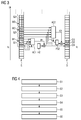
- FIG. 3 shows a relevant to the invention section of a block diagram of a hearing aid according to the invention. From this, the splitting of a frequency spectrum which can be transmitted by the hearing aid device or of an input signal into a number of frequency bands, namely the source frequency bands S, can be seen first. In this case, four adjacent frequency bands are combined to form a first group G1, five frequency bands adjoining the first group G1 and likewise adjacent to one another form a second group G2 etc.
- the signal components of the input signal in the individual frequency bands of the first group G1 are fed to a signal analysis and control unit AC1 which supplies signal components of the input signal in the individual frequency bands of the second group G2 to a signal analysis and control unit AC2.
- the signal level in the individual frequency bands is determined.
- the frequency band with the largest signal level is in each case the "winner frequency band" W1, W2, W3 etc of the relevant group G1, G2, G3 etc and is transferred by means of a frequency shift in the respective group associated target frequency band D1, D2, D3 etc and the in the respective target frequency band D1, D2, D3 etc possibly already existing signal component mixed from the input signal.
- both signal components are added.
- a form factor F1, F2, etc is determined, which is preferably proportional to the energy of the signal components of the input signal present in the frequency bands of the respective group G1, G2, G3 etc.
- Calculation methods for determining the form factors F1, F2, etc. are given by way of example in equations E1 to E4.
- the Form factors F1, F2 etc each serve as a multiplier for the selected frequency band of the group in question or the signal component of the input signal contained therein.
- the multiplication by the form factor F can be carried out before the frequency shift or after the frequency shift (as shown in the exemplary embodiment).
- the non-selected frequency bands of the group in question also influence the resulting signal in the target frequency band of the group.
- sound signals which differ substantially only in the signal components of the suppressed frequency bands of a group can be better distinguished from one another.
- a hearing aid designed to carry out a method according to the invention comprises at least one filter bank for dividing a frequency range which can be transmitted by the hearing aid into a multiplicity of frequency bands S. It also comprises means for dividing certain frequency bands into different groups G1, G2, G3, etc of frequency bands. The division of the frequency bands can be determined for example by programming the hearing aid and adapted to the individual hearing loss of a user. Furthermore, a hearing aid device according to the invention comprises means for selecting a frequency band W1, W2 etc from each group G1, G2, G3 etc of frequency bands as a function of the signal components of an input signal entering the hearing aid in the individual frequency bands of the respective group G1, G2, G3 etc frequency bands. For selection, at least one signal analysis and evaluation unit AC1, AC2, etc.
- the hearing aid device determines, for example, the signal levels and / or energy present in the individual channels and the frequency band as "winner frequency band" W1, W2 etc of the respective group G1, G2, G3 etc, which has the highest signal level and / or energy for a certain period of time.
- the hearing aid according to the invention comprises means for transferring the respectively selected frequency band W1, W2 etc in a target frequency band D1, D2, D3 etc.
- the frequency shift units FS1 and FS2 are available for this, each shift a specific frequency range in a different frequency range or convict.
- a hearing aid according to the invention also comprises means for respectively determining a gain of a signal component of the input signal or a signal resulting from this signal component in the selected frequency band W1, W2, as a function of signal components in non-selected frequency bands of the groups G1, G2, G3, etc of frequency bands ,
- the determination of the form factors F1, F2, etc also takes place through the signal analysis and evaluation units AC1, AC2, etc.
- FIG. 4 Illustrates graphically again the process steps performed in a method according to the invention in the frequency compression of an incoming input signal to a hearing aid:
- a frequency range which can be transmitted by the hearing aid device is split into a plurality of frequency bands.
- an incoming into the hearing aid input signal is split into signal components in the respective frequency bands.
- a plurality of adjacent frequency bands are combined to form at least one group of frequency bands.
- a method step S3 by a selection of a frequency band from the respective group for each group of frequency bands.
- a respective form factor is determined for each selected frequency band, in the calculation of which the signal components of the non-selected frequency bands of the respective group of frequency bands are received.
Landscapes
- Health & Medical Sciences (AREA)
- General Health & Medical Sciences (AREA)
- Neurosurgery (AREA)
- Otolaryngology (AREA)
- Physics & Mathematics (AREA)
- Engineering & Computer Science (AREA)
- Acoustics & Sound (AREA)
- Signal Processing (AREA)
- Circuit For Audible Band Transducer (AREA)
- Tone Control, Compression And Expansion, Limiting Amplitude (AREA)
Abstract
Description
- Die Erfindung betrifft ein Verfahren zur Frequenzkompression eines in ein Hörhilfegerät eingehenden Eingangssignals mit folgenden Schritten:
- Aufteilung eines von dem Hörhilfegerät übertragbaren Frequenzbereiches in mehrere Frequenzbänder,
- Zusammenfassen mehrerer aneinandergrenzender Frequenzbänder zu wenigstens einer Gruppe von Frequenzbändern,
- Auswahl eines der Frequenzbänder aus der Gruppe von Frequenzbändern,
- Überführen des ausgewählten Frequenzbandes in ein ZielFrequenzband.
- Ferner betrifft die Erfindung ein Hörhilfegerät zur Durchführung eines derartigen Verfahrens.
- Zum Ausgleich eines individuellen Hörverlustes eines Benutzers erfolgt in einem Hörhilfegerät gewöhnlich eine frequenzabhängige Verstärkung eines in das Hörhilfegerät eingehenden Eingangssignals. In der Regel ist der Dynamikbereich, d.h. der Bereich zwischen der Hörschwelle und der Unbehaglichkeitsschwelle, bei einem Schwerhörigen gegenüber einem Normalhörenden stark eingeschränkt. Deshalb führen moderne Hörhilfegeräte in der Regel mittels einer automatischen Verstärkungsregelung (AGC = automatic gain control) auch eine Dynamikkompression durch.
- Es gibt jedoch auch Hörverluste, bei denen durch eine reine frequenzabhängige Verstärkung eines akustischen Eingangssignals der Hörverlust nicht in einer befriedigenden Weise ausgeglichen werden kann. Beispiele hierfür sind Hörverluste mit toten Frequenzbereichen, in denen spektrale Komponenten des akustischen Eingangssignals auch durch eine hohe Verstärkung nicht hörbar gemacht werden können.
- Aus der
DE 10 2006 019 728 A1 ist ein Verfahren zum Einstellen einer Hörhilfevorrichtung bekannt, bei dem ein Anteil eines Eingangssignalspektrums bei einer ersten Frequenz verstärkt und zu einer zweiten Frequenz in Abhängigkeit von der Zeit verschoben wird, um einerseits eine hohe Spontanakzeptanz des Hörsystems durch ein zwischen zwei Adaptionsschritten nahezu unverfälschtes Klangbild des Hörsystems zu erreichen und andererseits den Lern- und Akklimatisationsprozess seitens des Hörgeschädigten an die neuen Frequenzmuster zu unterstützen. - Eine Möglichkeit zur Lösung des zuletzt genannten Problems bietet die sog. Frequenzkompression. Dabei werden spektrale Komponenten innerhalb eines Quellspektralbereiches (typisch bei höheren Frequenzen) in einen Zielfrequenzbereich (typisch bei niedrigeren Frequenzen) verschoben. Im Unterschied zu den im Quellfrequenzbereich liegenden Signalanteilen des akustischen Eingangssignals können die in den Zielfrequenzbereich verschobenen Signalanteile in diesem Frequenzbereich durch Verstärkung hörbar gemacht werden.
- Ein mögliches Verfahren zur Frequenzkompression sieht dabei folgende Verfahrensschritte vor:
- Aufteilung eines von dem Hörhilfegerät übertragbaren Frequenzbereiches in mehrere Frequenzbänder (Kanäle),
- Zusammenfassen mehrerer aneinandergrenzender Frequenzbänder zu wenigstens einer Gruppe von Frequenzbändern,
- Auswahl eines der Frequenzbänder aus der Gruppe von Frequenzbändern,
- Überführen des ausgewählten Frequenzbandes in ein Zielfrequenzband,
- ggf. Unterdrücken der nicht ausgewählten Frequenzbänder aus der Gruppe von Frequenzbändern.
- Nachteilig bei dieser Vorgehensweise ist jedoch, dass Schallsignale, die sich hauptsächlich im Inhalt der nicht ausgewählten Kanäle unterscheiden, nach der Frequenzkompression nur schwer oder nicht mehr unterscheidbar sind.
- Aufgabe der vorliegenden Erfindung ist es daher, eine Lösung für das genannte Problem zu finden und eine bessere Unterscheidbarkeit von Schallsignalen, die sich hauptsächlich im Inhalt nicht ausgewählter Kanäle unterscheiden, zu erreichen.
- Diese Aufgabe wird bei einem Verfahren zur Frequenzkompression der eingangs genannten Art dadurch gelöst, dass eine Verstärkung eines in dem ausgewählten Frequenzband liegenden Signalanteils des Eingangssignals oder eines aus diesem Signalanteil hervorgehenden Signals in Abhängigkeit von Signalanteilen in nicht ausgewählten Frequenzbändern der Gruppe von Frequenzbändern erfolgt.
- Durch die Bestimmung der Verstärkung in Abhängigkeit der Signalanteile in nicht ausgewählten Frequenzbändern erfahren auch die unterdrückten Frequenzbänder (soll heißen: die Signalanteile des Eingangssignals in den nicht ausgewählten Frequenzbändern) innerhalb einer Gruppe von Frequenzbändern noch eine gewisse Berücksichtigung im Zielfrequenzband der Gruppe. Beinhaltet die Gruppe unterdrückter Frequenzbänder ein hohes Maß an Schallenergie, so resultiert daraus eine vergleichsweise hohe Verstärkung für das ausgewählte Frequenzband der Gruppe in dem Zielfrequenzband. Im Unterschied dazu wird bei einer anderen Gruppe von Frequenzbändern, in der die unterdrückten Frequenzbänder nur ein geringes Maß an Schallenergie aufweisen, das von dem ausgewählten Frequenzband in das zugehörige Zielfrequenzband überführte Signal entsprechend weniger verstärkt bzw. abgeschwächt. Die Erfindung bewirkt somit eine unterschiedliche Gewichtung der in die einzelnen Zielfrequenzbänder überführten Signalanteile, wobei in diese Gewichtung auch die Signalanteile des Eingangsignals in den unterdrückten Frequenzbändern mit eingehen. Dadurch können Schallsignale, die sich hauptsächlich in den unterdrückten Frequenzbändern unterscheiden, besser unterschieden werden.
- Die Verstärkung des Signalanteils des Eingangssignals in dem ausgewählten Frequenzband kann entweder vor der Überführung in das Zielfrequenzband oder nach der Überführung, also nach der Frequenzverschiebung erfolgen. Dabei kann im Zusammenhang mit der Erfindung die Verstärkung für bestimmte ausgewählte Frequenzbänder auch kleiner 1, also eine Dämpfung sein.
- Gemäß der Erfindung erfolgt eine Verstärkung eines in dem ausgewählten Frequenzband liegenden Signalanteils des Eingangssignals oder eines aus diesem Signalanteil hervorgehenden Signals in Abhängigkeit eines Signalanteils des Eingangssignals aus wenigstens einem nicht ausgewählten Frequenzband der Gruppe von Frequenzbändern. Vorteilhaft gehen jedoch die Signalanteile mehrerer nicht ausgewählter Frequenzbänder, vorzugsweise die Signalanteile aller nicht ausgewählten Frequenzbänder in die Berechnung der Verstärkung ein.
- Bei einer bevorzugten Ausführungsform der Erfindung wird ein Formfaktor F bestimmt, der vom spektralen Inhalt aller Frequenzbänder innerhalb einer Gruppe von Frequenzbändern abhängt. Je reicher das Eingangssignal in spektraler Hinsicht innerhalb einer bestimmten Gruppe an Frequenzbändern ist, desto größer ist der Formfaktor dieser Gruppe. Der Formfaktor wirkt als Verstärkungsfaktor, mit dem das ausgewählte Frequenzband innerhalb einer Gruppe an Frequenzbändern bzw. das betreffende Zielfrequenzband beaufschlagt wird. Vorteilhaft wird der Signalanteil des Eingangssignals in dem ausgewählten Frequenzband oder das in das betreffende Zielfrequenzband überführte Signal mit dem Formfaktor multipliziert.
- Es gibt eine Vielzahl unterschiedlicher Möglichkeiten zur Bestimmung des Formfaktors, die zur Durchführung des erfindungsgemäßen Verfahrens geeignet sind.
- Gemäß einer ersten Variante der Erfindung berechnet sich ein Formfaktor FA aus dem Quotienten aus der Summe der Beträge der Signale aller Frequenzbänder einer Gruppe und dem Betrag des Signals des ausgewählten Frequenzbandes:

- Gemäß einer zweiten Variante der Erfindung berechnet sich ein Formfaktor FB aus dem Quotienten aus der Summe der Quadrate von den Beträgen der Signale aller Frequenzbänder einer Gruppe und dem Quadrat des Betrages des Signals des ausgewählten Frequenzbandes:

- Gemäß einer dritten Variante der Erfindung berechnet sich ein Formfaktor FC entsprechend dem Formfaktor FA, mit dem Unterschied gegenüber FA, dass bei FC die Summe der Beträge der der Signale aller Frequenzbänder auf die Anzahl der Frequenzbänder der betreffenden Gruppe normiert wird:

- Gemäß einer vierten Variante der Erfindung berechnet sich ein Formfaktor FD entsprechend dem Formfaktor FB, mit dem Unterschied gegenüber FB, dass bei FD die Summe der Quadrate von den Beträgen der Signale aller Frequenzbänder auf die Anzahl der Frequenzbänder der betreffenden Gruppe normiert wird:

- Die Erfindung ist nicht auf die beispielhaft für die Formfaktoren FA bis FD genannten Berechnungsmethoden beschränkt. Vielmehr ist eine Vielzahl weiterer Möglichkeiten zur Bestimmung des Formfaktors denkbar. Insbesondere können in die beispielhaft genannten Formfaktoren noch Multiplikationen mit Konstanten und/oder weiteren Variablen eingehen. Ferner ist es möglich, dass - anders als in den obigen Beispielen - in die jeweilige Zählerberechnung nicht stets die Signale aller Frequenzbänder der jeweiligen Gruppe eingehen. Insbesondere ist es möglich, dass das Signal in dem jeweils ausgewählten Frequenzband nicht in die Berechnung des Formfaktors eingeht.
- Die Erfindung wird nachfolgend anhand von Ausführungsbeispielen näher erläutert. Dabei zeigen:
- FIG 1
- ein Hörgerät nach dem Stand der Technik im vereinfachten Blockschaltbild,
- FIG 2
- die Einteilung einer Anzahl an Frequenzbändern in unterschiedliche Gruppen von Frequenzbändern, die Auswahl eines ausgewählten Frequenzbandes aus jeder Gruppe von Frequenzbändern und die Überführung des jeweils ausgewählten Frequenzbandes auf jeweils ein der betreffenden Gruppe zugeordnetes Zielfrequenzband,
- FIG 3
- die Auswahl eines Frequenzbandes aus jeder Gruppe von Frequenzbändern und die Überführung des ausgewählten Frequenzbandes auf jeweils ein der betreffenden Gruppe zugeordnetes Zielfrequenzband, und
- FIG 4
- ein Ablaufdiagramm bei der Durchführung eines erfindungsgemäßen Verfahrens.
-
FIG 1 zeigt im stark vereinfachten Blockschaltbild beispielhaft den Aufbau eines Hörhilfegerätes, insbesondere eines hinter dem Ohr tragbaren Hörgerätes, nach dem Stand der Technik. Hörgeräte umfassen prinzipiell als wesentliche Komponenten einen Eingangswandler, einen Verstärker und einen Ausgangswandler. Der Eingangswandler ist in der Regel ein Schallempfänger, z. B. ein Mikrofon, und/oder ein elektromagnetischer Empfänger, z. B. eine Induktionsspule. Der Ausgangswandler ist meist als elektroakustischer Wandler, z. B. Miniaturlautsprecher bzw. Hörer, oder als elektromechanischer Wandler, z. B. Knochenleitungshörer, realisiert. Der Verstärker ist üblicherweise in eine Signalverarbeitungseinheit integriert. Bei dem Ausführungsbeispiel gemäßFIG 1 sind in ein zum Tragen hinter dem Ohr vorgesehenes Hörgerätegehäuse 1 ein oder mehrere Mikrofone 2 zur Aufnahme des Schalls aus der Umgebung eingebaut. Eine Signalverarbeitungseinheit 3, die sich ebenfalls in dem Hörgerätegehäuse 1 befindet, verarbeitet die Mikrofonsignale und verstärkt sie. Das Ausgangssignal der Signalverarbeitungseinheit 3 wird an einen Lautsprecher bzw. Hörer 4 übertragen, der ein akustisches Signal ausgibt. Der Schall wird gegebenenfalls über einen Schallschlauch, der mit einer Otoplastik im Gehörgang fixiert ist, zum Trommelfell des Benutzers übertragen. Die Energieversorgung des Hörgerätes und insbesondere die der Signalverarbeitungseinheit 3 erfolgt durch eine ebenfalls in dem Hörgerätegehäuse 1 angeordnete Batterie 5. - Aus
FIG 2 ist die Aufteilung des von einem Hörhilfegerät übertragbaren Frequenzbereiches in eine Vielzahl an Frequenzbändern ersichtlich. Im Ausführungsbeispiel ist die Breite der Frequenzbänder bei allen Frequenzbändern gleich (z.B. 200 Hz), was jedoch nicht notwendigerweise so sein muss. Bei der Frequenzkompression wird allgemein ein Quellfrequenzbereich S in einen Zielfrequenzbereich D abgebildet bzw. überführt. Unterhalb einer bestimmten Grenzfrequenz fc erfolgt im Ausführungsbeispiel keine Frequenzkompression und oberhalb der Grenzfrequenz fc wird jeweils eine bestimmte Anzahl nebeneinander liegender Frequenzbänder zu einer Gruppe an Frequenzbändern zusammengefasst. Im Ausführungsbeispiel ist dies für die Gruppen G1, G2 und G3 dargestellt. Die Anzahl der Frequenzbänder innerhalb einer Gruppe kann zwischen den Gruppen variieren. Jeder Gruppe an Frequenzbändern G1, G2, G3 etc ist genau ein Zielfrequenzband D1, D2, D3 etc zugeordnet. Aus jeder Gruppe von Frequenzbändern G1, G2, G3 etc wird - z.B. für eine bestimmte Zeitdauer - ein bestimmtes Frequenzband (das "Gewinner-Frequenzband") ausgewählt, beispielsweise das Frequenzband, in dem der Signalanteil des Eingangssignals den höchsten Signalpegel im Vergleich zu den Signalanteilen in den anderen Frequenzbändern der Gruppe aufweist, und in das der Gruppe zugeordnete Zielfrequenzband verschoben. Im Ausführungsbeispiel wurden die Gewinner-Frequenzbänder W1, W2 und W3 wie gezeigt ausgewählt und in die Frequenzbänder D1, D2 und D3 verschoben. Die anderen, d.h. nicht ausgewählten Frequenzbänder jeder Gruppe werden nicht auf einen anderen Frequenzbereich abgebildet und daher zumindest aus Sicht des schwerhörigen Benutzers unterdrückt. Ggf. können nicht ausgewählte und damit unterdrückte Frequenzbänder auch aktiv unterdrückt, das heißt durch Filtermittel im Hörhilfegerät bezüglich des Eingangssignals gedämpft bzw. herausgefiltert werden. Ferner ist es möglich, dass Signalanteile des Eingangssignals im Ausgangssignal eines betreffenden Hörhilfegerätes dadurch unterdrückt sind, dass für die entsprechenden Signalanteile nach der Aufteilung in Frequenzbänder keine weitere Signalverarbeitung erfolgt. - In der Regel wird der aus dem ausgewählten Frequenzband W1, W2, W3 in das Zielfrequenzband verschobene Signalanteil dem ohnehin in dem Zielfrequenzband vorhandene Signalanteil des Eingangssignals überlagert. Dies kann durch eine einfache Addition beider Signale erfolgen, es kann jedoch auch ein bestimmtes Mischverhältnis bzw. eine unterschiedliche Gewichtung der Signale eingestellt werden. Dies kann sogar soweit gehen, dass z.B. der direkt aus dem Eingangssignal resultierende Signalanteil in dem betreffenden Frequenzband vollständig unterdrückt (herausgefiltert) wird und nur noch das aus einem anderen Frequenzband in das betreffende Frequenzband verschobene Signal weiterverarbeitet wird.
- Gemäß der Erfindung wird vorteilhaft aus allen Frequenzbändern einer Gruppe ein Formfaktor ermittelt und das ausgewählte Frequenzband dieser Gruppe mit dem betreffenden Formfaktor beaufschlagt. Beispielsweise wird der in dem ausgewählten Frequenzband liegende Signalanteil des Eingangssignals mit dem Formfaktor multipliziert, wodurch eine Verstärkung oder Dämpfung des Signalanteils bewirkt wird. Der Formfaktor ist insbesondere ein Maß der Schallenergie aller Kanäle der betreffenden Gruppe. Da sich die aus den einzelnen Gruppen von Frequenzbändern resultierenden Formfaktoren in der Regel unterscheiden, resultiert daraus eine unterschiedliche Gewichtung der aus den einzelnen Gruppen von Frequenzbändern jeweils ausgewählten Frequenzbänder bzw. der Signalanteile des Eingangssignals in diesen Frequenzbändern.
-
FIG 3 zeigt einen für die Erfindung relevanten Abschnitt eines Blockschaltbildes eines erfindungsgemäßen Hörhilfegerätes. Daraus ist zunächst die Aufspaltung eines von dem Hörhilfegerät übertragbaren Frequenzspektrums bzw. eines Eingangsignals in eine Anzahl an Frequenzbändern, nämlich die Quellfrequenzbänder S ersichtlich. Dabei sind vier nebeneinander liegende Frequenzbänder zu einer ersten Gruppe G1, fünf an die erste Gruppe G1 anschließende und ebenfalls nebeneinander liegende Frequenzbänder zu einer zweiten Gruppe G2 etc zusammengefasst. Die Signalanteile des Eingangssignals in den einzelnen Frequenzbändern der ersten Gruppe G1 sind einer Signalanalyse- und Steuereinheit AC1, die Signalanteile des Eingangssignals in den einzelnen Frequenzbändern der zweiten Gruppe G2 einer Signalanalyse- und Steuereinheit AC2 etc zugeführt. In der jeweiligen Signalanalyse- und Steuereinheit wird zunächst der Signalpegel in den einzelnen Frequenzbändern bestimmt. Das Frequenzband mit dem größten Signalpegel ist jeweils das "Gewinner-Frequenzband" W1, W2, W3 etc der betreffenden Gruppe G1, G2, G3 etc und wird mittels einer Frequenzverschiebung in ein der jeweiligen Gruppe zugeordnetes Zielfrequenzband D1, D2, D3 etc überführt und dem im jeweiligen Zielfrequenzband D1, D2, D3 etc gegebenenfalls ohnehin vorhandenen Signalanteil aus dem Eingangssignal gemischt. Insbesondere werden beide Signalanteile addiert. - Weiterhin wird mittels der jeweiligen Signalanalyse- und Steuereinheit AC1, AC2, etc jeweils ein Formfaktor F1, F2, etc ermittelt, der vorzugsweise proportional zu der Energie der in den Frequenzbändern der jeweiligen Gruppe G1, G2, G3 etc vorhandenen Signalanteile des Eingangssignals ist. Berechnungsmethoden zur Bestimmung der Formfaktoren F1, F2 etc sind beispielhaft in den Gleichungen E1 bis E4 angegeben. Die Formfaktoren F1, F2 etc dienen jeweils als Multiplikator für das ausgewählte Frequenzband der betreffenden Gruppe bzw. den darin enthaltenen Signalanteil des Eingangssignals. Dabei kann die Multiplikation mit dem Formfaktor F jeweils vor der Frequenzverschiebung oder nach der Frequenzverschiebung (wie im Ausführungsbeispiel dargestellt) erfolgen. Durch die Multiplikation mit dem Formfaktor F nehmen auch die nicht ausgewählten Frequenzbänder der betreffenden Gruppe Einfluss auf das resultierende Signal im Zielfrequenzband der Gruppe. Dadurch können Schallsignale, die sich im Wesentlichen nur in den Signalanteilen der unterdrückten Frequenzbänder einer Gruppe unterscheiden, besser voneinander unterschieden werden.
- Ein zur Durchführung eines erfindungsgemäßen Verfahrens ausgebildetes Hörhilfegerät umfasst wenigstens eine Filterbank zur Aufteilung eines von dem Hörhilfegerät übertragbaren Frequenzbereiches in eine Vielzahl an Frequenzbändern S. Ferner umfasst es Mittel zur Einteilung bestimmter Frequenzbänder in unterschiedliche Gruppen G1, G2, G3 etc von Frequenzbändern. Die Einteilung der Frequenzbänder kann beispielsweise durch Programmierung des Hörhilfegerätes festgelegt und an den individuellen Hörverlust eines Benutzers angepasst werden. Weiterhin umfasst ein erfindungsgemäßes Hörhilfegerät Mittel zur Auswahl eines Frequenzbandes W1, W2 etc aus jeder Gruppe G1, G2, G3 etc von Frequenzbändern in Abhängigkeit von den Signalanteilen eines in das Hörhilfegerät eingehenden Eingangssignals in den einzelnen Frequenzbändern der jeweiligen Gruppe G1, G2, G3 etc von Frequenzbändern. Zur Auswahl ist wenigstens eine Signalanalyse- und Auswerteeinheit AC1, AC2, etc im Hörhilfegerät vorhanden, die beispielsweise die Signalpegel und/oder in den einzelnen Kanälen vorhandene Energie bestimmt und das Frequenzband als "Gewinner-Frequenzband" W1, W2 etc der jeweiligen Gruppe G1, G2, G3 etc festlegt, das für einen bestimmten Zeitraum den höchsten Signalpegel und/oder die größte Energie aufweist.
- Darüber hinaus umfasst das erfindungsgemäße Hörhilfegerät Mittel zum Überführen des jeweils ausgewählten Frequenzbands W1, W2 etc in ein Zielfrequenzband D1, D2, D3 etc. Im Ausführungsbeispiel sind hierfür die Frequenzverschiebeeinheiten FS1 und FS2 vorhanden, die jeweils einen bestimmten Frequenzbereich in einen anderen Frequenzbereich verschieben bzw. überführen.
- Schließlich umfasst ein erfindungsgemäßes Hörhilfegerät noch Mittel zur jeweiligen Bestimmung einer Verstärkung eines in dem ausgewählten Frequenzband W1, W2 etc liegenden Signalanteils des Eingangssignals oder eines aus diesem Signalanteil hervorgehenden Signals in Abhängigkeit von Signalanteilen in nicht ausgewählten Frequenzbändern der Gruppe G1, G2, G3 etc von Frequenzbändern. Im Ausführungsbeispiel erfolgt hierzu die Bestimmung der Formfaktoren F1, F2 etc ebenfalls durch die Signalanalyse- und Auswerteeinheiten AC1, AC2, etc.
-
FIG 4 veranschaulicht grafisch nochmals die bei einem erfindungsgemäßen Verfahren ausgeführten Verfahrensschritte bei der Frequenzkompression eines in ein Hörhilfegerät eingehenden Eingangssignals: - In einem ersten Verfahrensschritt S1 erfolgt eine Aufteilung eines von dem Hörhilfegerät übertragbaren Frequenzbereiches in mehrere Frequenzbänder. Dadurch wird ein in das Hörhilfegerät eingehendes Eingangssignal in Signalanteile in den jeweiligen Frequenzbändern aufgespaltet. Nachfolgend werden in einem Verfahrensschritt S2 jeweils mehrere aneinandergrenzende Frequenzbänder zu wenigstens einer Gruppe von Frequenzbändern zusammengefasst. Darauf folgt in einem Verfahrensschritt S3 für jede Gruppe von Frequenzbändern eine Auswahl eines Frequenzbandes aus der jeweiligen Gruppe. In einem Verfahrensschritt S4 wird für jedes ausgewählte Frequenzband jeweils ein Formfaktor bestimmt, in dessen Berechnung jeweils auch die Signalanteile der nicht ausgewählten Frequenzbänder der betreffenden Gruppe von Frequenzbändern eingehen. Es erfolgt dann in einem Verfahrensschritt S5 für jede Gruppe von Frequenzbändern eine Multiplikation des Signalanteils in dem ausgewählten Frequenzband mit dem zuvor für die betreffende Gruppe ermittelten Formfaktor. Dabei kann die Multiplikation vor oder nach der Verschiebung des Signalanteils in den betreffenden Zielfrequenzbereich (Verfahrensschritt S6) erfolgen. Die nicht ausgewählten Frequenzbänder einer jeden Gruppe werden nicht weiterverarbeitet und damit unterdrückt.
Claims (8)
- Verfahren zur Frequenzkompression eines in ein Hörhilfegerät eingehenden Eingangssignals mit folgenden Schritten:- Aufteilung eines von dem Hörhilfegerät übertragbaren Frequenzbereiches in mehrere Frequenzbänder,- Zusammenfassen mehrerer aneinandergrenzender Frequenzbänder zu wenigstens einer Gruppe (G1, G2, G3) von Frequenzbändern,- Auswahl eines Frequenzbandes (W1, W2, W3) aus der Gruppe (G1, G2, G3) von Frequenzbändern,- Überführen des ausgewählten Frequenzbandes in ein Zielfrequenzband (D1, D2, D3),
dadurch gekennzeichnet, dass eine Verstärkung eines in dem ausgewählten Frequenzband (W1, W2, W3) liegenden Signalanteils des Eingangssignals oder eines aus diesem Signalanteil hervorgehenden Signals in Abhängigkeit eines Signalanteils des Eingangssignals aus wenigstens einem nicht ausgewählten Frequenzband der Gruppe von Frequenzbändern erfolgt. - Verfahren nach Anspruch 1, wobei die Verstärkung eines aus dem ausgewählten Frequenzband (W1, W2, W3) in das Zielfrequenzband (D1, D2, D3) überführten Signalanteils bestimmt wird.
- Verfahren nach Anspruch 1 oder 2, wobei innerhalb der Gruppe (G1, G2, G3) von Frequenzbändern das Frequenzband mit der höchsten Schallenergie und/oder dem größten Signalpegel ausgewählt wird.
- Verfahren nach einem der Ansprüche 1 bis 3, wobei der in dem ausgewählten Frequenzband (W1, W2, W3) liegende Signalanteil oder das aus diesem Signalanteil hervorgehende Signal mit einem Formfaktor (F1, F2) multipliziert wird, der von dem Signalanteil des Eingangssignals aus dem nicht ausgewählten Frequenzband der Gruppe (G1, G2, G3) von Frequenzbändern abhängt.
- Verfahren nach Anspruch 4, wobei in die Berechnung des Formfaktors (F1, F2) einer der folgenden Terme eingeht:


- Verfahren nach Anspruch 4 oder 5, wobei der Formfaktor (F1, F2) eine für das ausgewählte Frequenzband (W1, W2, W3) oder das Zielfrequenzband (D1, D2, D3) des ausgewählten Frequenzbandes maßgebliche Verstärkung beeinflusst.
- Verfahren nach einem der Ansprüche 4 bis 6, wobei für jede Gruppe (G1, G2, G3) von Frequenzbändern ein Formfaktor (F1, F2) bestimmt wird.
- Hörhilfegerät zur Durchführung eines Verfahrens nach einem der Ansprüche 1 bis 7, mit- einer Filterbank zur Aufteilung eines von dem Hörhilfegerät übertragbaren Frequenzbereiches in eine Vielzahl an Frequenzbändern,- Mitteln zur Einteilung bestimmter Frequenzbänder in unterschiedliche Gruppen (G1, G2, G3) von Frequenzbändern,- Mitteln zur Auswahl eines Frequenzbandes (W1, W2, W3) aus jeder Gruppe (G1, G2, G3) von Frequenzbändern in Abhängigkeit von Signalanteilen eines in das Hörhilfegerät eingehenden Eingangssignals in den einzelnen Frequenzbändern der jeweiligen Gruppe (G1, G2, G3) von Frequenzbändern,- Mitteln zum Überführen des jeweils ausgewählten Frequenzbands (W1, W2, W3) in ein Zielfrequenzband (D1, D2, D3),- Mitteln zur jeweiligen Bestimmung einer Verstärkung eines in dem ausgewählten Frequenzband (W1, W2, W3) liegenden Signalanteils des Eingangssignals oder eines aus diesem Signalanteil hervorgehenden Signals in Abhängigkeit von einem Signalanteil des Eingangssignals in wenigstens einem nicht ausgewählten Frequenzband der Gruppe (G1, G2, G3) von Frequenzbändern.
Applications Claiming Priority (1)
| Application Number | Priority Date | Filing Date | Title |
|---|---|---|---|
| DE102010041640.1A DE102010041640B4 (de) | 2010-09-29 | 2010-09-29 | Hörhilfegerät zur Frequenzkompression |
Publications (2)
| Publication Number | Publication Date |
|---|---|
| EP2437522A1 true EP2437522A1 (de) | 2012-04-04 |
| EP2437522B1 EP2437522B1 (de) | 2013-04-10 |
Family
ID=44674297
Family Applications (1)
| Application Number | Title | Priority Date | Filing Date |
|---|---|---|---|
| EP11178382.5A Active EP2437522B1 (de) | 2010-09-29 | 2011-08-23 | Hörhilfegerät zur Frequenzkompression |
Country Status (5)
| Country | Link |
|---|---|
| EP (1) | EP2437522B1 (de) |
| JP (1) | JP5269165B2 (de) |
| AU (1) | AU2011226931B2 (de) |
| DE (1) | DE102010041640B4 (de) |
| DK (1) | DK2437522T3 (de) |
Citations (3)
| Publication number | Priority date | Publication date | Assignee | Title |
|---|---|---|---|---|
| DE1261169B (de) * | 1963-02-14 | 1968-02-15 | Centre Nat Rech Scient | Hoerhilfe |
| WO2000075920A1 (en) * | 1999-06-03 | 2000-12-14 | Telefonaktiebolaget Lm Ericsson (Publ) | A method of improving the intelligibility of a sound signal, and a device for reproducing a sound signal |
| DE102006019728A1 (de) | 2006-04-27 | 2007-11-15 | Siemens Audiologische Technik Gmbh | Zeit-adaptives Einstellen einer Hörhilfevorrichtung und entsprechendes Verfahren |
Family Cites Families (5)
| Publication number | Priority date | Publication date | Assignee | Title |
|---|---|---|---|---|
| JPS5755700A (en) * | 1980-09-20 | 1982-04-02 | Shigeru Egashira | Frequency-compression hearing aid |
| JPS57178499A (en) * | 1981-04-27 | 1982-11-02 | Horiguchi Shinsaku | Hearing aid |
| JP2904272B2 (ja) * | 1996-12-10 | 1999-06-14 | 日本電気株式会社 | ディジタル補聴器、及びその補聴処理方法 |
| WO2007000161A1 (en) * | 2005-06-27 | 2007-01-04 | Widex A/S | Hearing aid with enhanced high frequency reproduction and method for processing an audio signal |
| JP4886783B2 (ja) * | 2005-09-01 | 2012-02-29 | ヴェーデクス・アクティーセルスカプ | 補聴器の帯域分割コンプレッサを制御する方法および装置 |
-
2010
- 2010-09-29 DE DE102010041640.1A patent/DE102010041640B4/de active Active
-
2011
- 2011-08-23 EP EP11178382.5A patent/EP2437522B1/de active Active
- 2011-08-23 DK DK11178382.5T patent/DK2437522T3/da active
- 2011-09-27 JP JP2011211120A patent/JP5269165B2/ja active Active
- 2011-09-28 AU AU2011226931A patent/AU2011226931B2/en not_active Ceased
Patent Citations (3)
| Publication number | Priority date | Publication date | Assignee | Title |
|---|---|---|---|---|
| DE1261169B (de) * | 1963-02-14 | 1968-02-15 | Centre Nat Rech Scient | Hoerhilfe |
| WO2000075920A1 (en) * | 1999-06-03 | 2000-12-14 | Telefonaktiebolaget Lm Ericsson (Publ) | A method of improving the intelligibility of a sound signal, and a device for reproducing a sound signal |
| DE102006019728A1 (de) | 2006-04-27 | 2007-11-15 | Siemens Audiologische Technik Gmbh | Zeit-adaptives Einstellen einer Hörhilfevorrichtung und entsprechendes Verfahren |
Also Published As
| Publication number | Publication date |
|---|---|
| DE102010041640A1 (de) | 2012-03-29 |
| AU2011226931A1 (en) | 2012-04-12 |
| DE102010041640B4 (de) | 2014-01-30 |
| EP2437522B1 (de) | 2013-04-10 |
| AU2011226931B2 (en) | 2013-09-05 |
| JP2012075106A (ja) | 2012-04-12 |
| DK2437522T3 (da) | 2013-07-15 |
| JP5269165B2 (ja) | 2013-08-21 |
Similar Documents
| Publication | Publication Date | Title |
|---|---|---|
| DE69906560T2 (de) | Cochlea-kompression modellbasiertes hörhilfegerät | |
| EP2437258B1 (de) | Verfahren und Vorrichtung zur Frequenzkompression mit selektiver Frequenzverschiebung | |
| DE102010041740A1 (de) | Verfahren zur Signalverarbeitung in einem Hörhilfegerät sowie Hörhilfegerät | |
| EP2919485B1 (de) | Übertragung eines windreduzierten Signals mit verminderter Latenzzeit | |
| EP1850635A1 (de) | Zeit-adaptives Einstellen einer Hörhilfevorrichtung und entsprechendes Verfahren | |
| EP2437520B1 (de) | Hörhilfegerät zur Frequenzkompression | |
| DE102008024535A1 (de) | Verfahren zum Optimieren einer mehrstufigen Filterbank sowie entsprechende Filterbank und Hörvorrichtung | |
| EP1912470B1 (de) | Verfahren zur Dynamikkompression eines Audiosignals und entsprechende Hörvorrichtung | |
| DE102012203349B4 (de) | Verfahren zum Anpassen einer Hörvorrichtung anhand des Sensory Memory und Anpassvorrichtung | |
| DE102008046040A1 (de) | Verfahren zum Betrieb einer Hörvorrichtung mit Richtwirkung und zugehörige Hörvorrichtung | |
| EP1850634A2 (de) | Verfahren zum Einstellen eines Hörgeräts mit Hochfrequenzverstärkung | |
| EP2584795B1 (de) | Verfahren zum Ermitteln einer Kompressionskennlinie | |
| EP2437522B1 (de) | Hörhilfegerät zur Frequenzkompression | |
| DE102009058415B4 (de) | Verfahren zur Frequenztransposition bei einem Hörhilfegerät sowie Hörhilfegerät | |
| EP2437521B1 (de) | Verfahren zur Frequenzkompression mit harmonischer Korrektur und entsprechende Vorrichtung | |
| DE102010041775B4 (de) | Verfahren zum Anpassen einer Hörvorrichtung mit Perzentilanalyse und Anpassvorrichtung | |
| EP3048813B1 (de) | Verfahren und vorrichtung zur rauschunterdrückung basierend auf inter-subband-korrelation | |
| EP2622879B1 (de) | Verfahren und vorrichtung zur frequenzkompression | |
| WO2012041372A1 (de) | Verfahren zur frequenzkompression, anpasseinrichtung und hörvorrichtung | |
| DE102011087692B4 (de) | Hörvorrichtung und Verfahren zur Verbesserung der Wahrnehmbarkeit eines Anteils eines Eingangssignals für einen Benutzer der Hörvorrichtung | |
| EP2575377A1 (de) | Verstärkungseinstellung bei einem Hörhilfegerät | |
| DE102019126509A1 (de) | Verbesserung der subjektiven bass-wahrnehmung eines audiosignals mit hilfe höherer harmonischer |
Legal Events
| Date | Code | Title | Description |
|---|---|---|---|
| PUAI | Public reference made under article 153(3) epc to a published international application that has entered the european phase |
Free format text: ORIGINAL CODE: 0009012 |
|
| AK | Designated contracting states |
Kind code of ref document: A1 Designated state(s): AL AT BE BG CH CY CZ DE DK EE ES FI FR GB GR HR HU IE IS IT LI LT LU LV MC MK MT NL NO PL PT RO RS SE SI SK SM TR |
|
| AX | Request for extension of the european patent |
Extension state: BA ME |
|
| 17P | Request for examination filed |
Effective date: 20120423 |
|
| GRAP | Despatch of communication of intention to grant a patent |
Free format text: ORIGINAL CODE: EPIDOSNIGR1 |
|
| GRAS | Grant fee paid |
Free format text: ORIGINAL CODE: EPIDOSNIGR3 |
|
| GRAA | (expected) grant |
Free format text: ORIGINAL CODE: 0009210 |
|
| AK | Designated contracting states |
Kind code of ref document: B1 Designated state(s): AL AT BE BG CH CY CZ DE DK EE ES FI FR GB GR HR HU IE IS IT LI LT LU LV MC MK MT NL NO PL PT RO RS SE SI SK SM TR |
|
| REG | Reference to a national code |
Ref country code: GB Ref legal event code: FG4D Free format text: NOT ENGLISH |
|
| REG | Reference to a national code |
Ref country code: AT Ref legal event code: REF Ref document number: 606584 Country of ref document: AT Kind code of ref document: T Effective date: 20130415 Ref country code: CH Ref legal event code: EP Ref country code: CH Ref legal event code: NV Representative=s name: SIEMENS SCHWEIZ AG, CH |
|
| REG | Reference to a national code |
Ref country code: IE Ref legal event code: FG4D Free format text: LANGUAGE OF EP DOCUMENT: GERMAN |
|
| REG | Reference to a national code |
Ref country code: DE Ref legal event code: R096 Ref document number: 502011000587 Country of ref document: DE Effective date: 20130606 |
|
| REG | Reference to a national code |
Ref country code: DK Ref legal event code: T3 |
|
| PG25 | Lapsed in a contracting state [announced via postgrant information from national office to epo] |
Ref country code: SI Free format text: LAPSE BECAUSE OF FAILURE TO SUBMIT A TRANSLATION OF THE DESCRIPTION OR TO PAY THE FEE WITHIN THE PRESCRIBED TIME-LIMIT Effective date: 20130410 |
|
| REG | Reference to a national code |
Ref country code: LT Ref legal event code: MG4D Ref country code: NL Ref legal event code: VDEP Effective date: 20130410 |
|
| PG25 | Lapsed in a contracting state [announced via postgrant information from national office to epo] |
Ref country code: PT Free format text: LAPSE BECAUSE OF FAILURE TO SUBMIT A TRANSLATION OF THE DESCRIPTION OR TO PAY THE FEE WITHIN THE PRESCRIBED TIME-LIMIT Effective date: 20130812 Ref country code: FI Free format text: LAPSE BECAUSE OF FAILURE TO SUBMIT A TRANSLATION OF THE DESCRIPTION OR TO PAY THE FEE WITHIN THE PRESCRIBED TIME-LIMIT Effective date: 20130410 Ref country code: IS Free format text: LAPSE BECAUSE OF FAILURE TO SUBMIT A TRANSLATION OF THE DESCRIPTION OR TO PAY THE FEE WITHIN THE PRESCRIBED TIME-LIMIT Effective date: 20130810 Ref country code: GR Free format text: LAPSE BECAUSE OF FAILURE TO SUBMIT A TRANSLATION OF THE DESCRIPTION OR TO PAY THE FEE WITHIN THE PRESCRIBED TIME-LIMIT Effective date: 20130711 Ref country code: NO Free format text: LAPSE BECAUSE OF FAILURE TO SUBMIT A TRANSLATION OF THE DESCRIPTION OR TO PAY THE FEE WITHIN THE PRESCRIBED TIME-LIMIT Effective date: 20130710 Ref country code: ES Free format text: LAPSE BECAUSE OF FAILURE TO SUBMIT A TRANSLATION OF THE DESCRIPTION OR TO PAY THE FEE WITHIN THE PRESCRIBED TIME-LIMIT Effective date: 20130721 Ref country code: LT Free format text: LAPSE BECAUSE OF FAILURE TO SUBMIT A TRANSLATION OF THE DESCRIPTION OR TO PAY THE FEE WITHIN THE PRESCRIBED TIME-LIMIT Effective date: 20130410 Ref country code: NL Free format text: LAPSE BECAUSE OF FAILURE TO SUBMIT A TRANSLATION OF THE DESCRIPTION OR TO PAY THE FEE WITHIN THE PRESCRIBED TIME-LIMIT Effective date: 20130410 Ref country code: SE Free format text: LAPSE BECAUSE OF FAILURE TO SUBMIT A TRANSLATION OF THE DESCRIPTION OR TO PAY THE FEE WITHIN THE PRESCRIBED TIME-LIMIT Effective date: 20130410 |
|
| PG25 | Lapsed in a contracting state [announced via postgrant information from national office to epo] |
Ref country code: PL Free format text: LAPSE BECAUSE OF FAILURE TO SUBMIT A TRANSLATION OF THE DESCRIPTION OR TO PAY THE FEE WITHIN THE PRESCRIBED TIME-LIMIT Effective date: 20130410 Ref country code: CY Free format text: LAPSE BECAUSE OF FAILURE TO SUBMIT A TRANSLATION OF THE DESCRIPTION OR TO PAY THE FEE WITHIN THE PRESCRIBED TIME-LIMIT Effective date: 20130410 Ref country code: BG Free format text: LAPSE BECAUSE OF FAILURE TO SUBMIT A TRANSLATION OF THE DESCRIPTION OR TO PAY THE FEE WITHIN THE PRESCRIBED TIME-LIMIT Effective date: 20130710 Ref country code: HR Free format text: LAPSE BECAUSE OF FAILURE TO SUBMIT A TRANSLATION OF THE DESCRIPTION OR TO PAY THE FEE WITHIN THE PRESCRIBED TIME-LIMIT Effective date: 20130410 Ref country code: LV Free format text: LAPSE BECAUSE OF FAILURE TO SUBMIT A TRANSLATION OF THE DESCRIPTION OR TO PAY THE FEE WITHIN THE PRESCRIBED TIME-LIMIT Effective date: 20130410 Ref country code: RS Free format text: LAPSE BECAUSE OF FAILURE TO SUBMIT A TRANSLATION OF THE DESCRIPTION OR TO PAY THE FEE WITHIN THE PRESCRIBED TIME-LIMIT Effective date: 20130410 |
|
| PG25 | Lapsed in a contracting state [announced via postgrant information from national office to epo] |
Ref country code: EE Free format text: LAPSE BECAUSE OF FAILURE TO SUBMIT A TRANSLATION OF THE DESCRIPTION OR TO PAY THE FEE WITHIN THE PRESCRIBED TIME-LIMIT Effective date: 20130410 Ref country code: SK Free format text: LAPSE BECAUSE OF FAILURE TO SUBMIT A TRANSLATION OF THE DESCRIPTION OR TO PAY THE FEE WITHIN THE PRESCRIBED TIME-LIMIT Effective date: 20130410 Ref country code: CZ Free format text: LAPSE BECAUSE OF FAILURE TO SUBMIT A TRANSLATION OF THE DESCRIPTION OR TO PAY THE FEE WITHIN THE PRESCRIBED TIME-LIMIT Effective date: 20130410 |
|
| PLBE | No opposition filed within time limit |
Free format text: ORIGINAL CODE: 0009261 |
|
| STAA | Information on the status of an ep patent application or granted ep patent |
Free format text: STATUS: NO OPPOSITION FILED WITHIN TIME LIMIT |
|
| BERE | Be: lapsed |
Owner name: SIEMENS MEDICAL INSTRUMENTS PTE. LTD. Effective date: 20130831 |
|
| PG25 | Lapsed in a contracting state [announced via postgrant information from national office to epo] |
Ref country code: RO Free format text: LAPSE BECAUSE OF FAILURE TO SUBMIT A TRANSLATION OF THE DESCRIPTION OR TO PAY THE FEE WITHIN THE PRESCRIBED TIME-LIMIT Effective date: 20130410 Ref country code: IT Free format text: LAPSE BECAUSE OF FAILURE TO SUBMIT A TRANSLATION OF THE DESCRIPTION OR TO PAY THE FEE WITHIN THE PRESCRIBED TIME-LIMIT Effective date: 20130410 |
|
| 26N | No opposition filed |
Effective date: 20140113 |
|
| REG | Reference to a national code |
Ref country code: DE Ref legal event code: R097 Ref document number: 502011000587 Country of ref document: DE Effective date: 20140113 |
|
| PG25 | Lapsed in a contracting state [announced via postgrant information from national office to epo] |
Ref country code: MC Free format text: LAPSE BECAUSE OF FAILURE TO SUBMIT A TRANSLATION OF THE DESCRIPTION OR TO PAY THE FEE WITHIN THE PRESCRIBED TIME-LIMIT Effective date: 20130410 |
|
| REG | Reference to a national code |
Ref country code: IE Ref legal event code: MM4A |
|
| PG25 | Lapsed in a contracting state [announced via postgrant information from national office to epo] |
Ref country code: BE Free format text: LAPSE BECAUSE OF NON-PAYMENT OF DUE FEES Effective date: 20130831 |
|
| PG25 | Lapsed in a contracting state [announced via postgrant information from national office to epo] |
Ref country code: IE Free format text: LAPSE BECAUSE OF NON-PAYMENT OF DUE FEES Effective date: 20130823 |
|
| REG | Reference to a national code |
Ref country code: DE Ref legal event code: R082 Ref document number: 502011000587 Country of ref document: DE Representative=s name: FDST PATENTANWAELTE FREIER DOERR STAMMLER TSCH, DE |
|
| REG | Reference to a national code |
Ref country code: DE Ref legal event code: R082 Ref document number: 502011000587 Country of ref document: DE Representative=s name: FDST PATENTANWAELTE FREIER DOERR STAMMLER TSCH, DE |
|
| PG25 | Lapsed in a contracting state [announced via postgrant information from national office to epo] |
Ref country code: SM Free format text: LAPSE BECAUSE OF FAILURE TO SUBMIT A TRANSLATION OF THE DESCRIPTION OR TO PAY THE FEE WITHIN THE PRESCRIBED TIME-LIMIT Effective date: 20130410 |
|
| PG25 | Lapsed in a contracting state [announced via postgrant information from national office to epo] |
Ref country code: TR Free format text: LAPSE BECAUSE OF FAILURE TO SUBMIT A TRANSLATION OF THE DESCRIPTION OR TO PAY THE FEE WITHIN THE PRESCRIBED TIME-LIMIT Effective date: 20130410 Ref country code: MT Free format text: LAPSE BECAUSE OF FAILURE TO SUBMIT A TRANSLATION OF THE DESCRIPTION OR TO PAY THE FEE WITHIN THE PRESCRIBED TIME-LIMIT Effective date: 20130410 |
|
| PG25 | Lapsed in a contracting state [announced via postgrant information from national office to epo] |
Ref country code: MK Free format text: LAPSE BECAUSE OF FAILURE TO SUBMIT A TRANSLATION OF THE DESCRIPTION OR TO PAY THE FEE WITHIN THE PRESCRIBED TIME-LIMIT Effective date: 20130410 Ref country code: LU Free format text: LAPSE BECAUSE OF NON-PAYMENT OF DUE FEES Effective date: 20130823 Ref country code: HU Free format text: LAPSE BECAUSE OF FAILURE TO SUBMIT A TRANSLATION OF THE DESCRIPTION OR TO PAY THE FEE WITHIN THE PRESCRIBED TIME-LIMIT; INVALID AB INITIO Effective date: 20110823 |
|
| REG | Reference to a national code |
Ref country code: DE Ref legal event code: R082 Ref document number: 502011000587 Country of ref document: DE Representative=s name: FDST PATENTANWAELTE FREIER DOERR STAMMLER TSCH, DE Ref country code: DE Ref legal event code: R081 Ref document number: 502011000587 Country of ref document: DE Owner name: SIVANTOS PTE. LTD., SG Free format text: FORMER OWNER: SIEMENS MEDICAL INSTRUMENTS PTE. LTD., SINGAPORE, SG |
|
| REG | Reference to a national code |
Ref country code: FR Ref legal event code: PLFP Year of fee payment: 6 |
|
| REG | Reference to a national code |
Ref country code: FR Ref legal event code: PLFP Year of fee payment: 7 |
|
| REG | Reference to a national code |
Ref country code: AT Ref legal event code: MM01 Ref document number: 606584 Country of ref document: AT Kind code of ref document: T Effective date: 20160823 |
|
| PG25 | Lapsed in a contracting state [announced via postgrant information from national office to epo] |
Ref country code: AT Free format text: LAPSE BECAUSE OF NON-PAYMENT OF DUE FEES Effective date: 20160823 |
|
| REG | Reference to a national code |
Ref country code: FR Ref legal event code: PLFP Year of fee payment: 8 |
|
| PG25 | Lapsed in a contracting state [announced via postgrant information from national office to epo] |
Ref country code: AL Free format text: LAPSE BECAUSE OF FAILURE TO SUBMIT A TRANSLATION OF THE DESCRIPTION OR TO PAY THE FEE WITHIN THE PRESCRIBED TIME-LIMIT Effective date: 20130410 |
|
| PGFP | Annual fee paid to national office [announced via postgrant information from national office to epo] |
Ref country code: DE Payment date: 20250724 Year of fee payment: 15 Ref country code: DK Payment date: 20250723 Year of fee payment: 15 |
|
| PGFP | Annual fee paid to national office [announced via postgrant information from national office to epo] |
Ref country code: GB Payment date: 20250725 Year of fee payment: 15 |
|
| PGFP | Annual fee paid to national office [announced via postgrant information from national office to epo] |
Ref country code: FR Payment date: 20250723 Year of fee payment: 15 |
|
| PGFP | Annual fee paid to national office [announced via postgrant information from national office to epo] |
Ref country code: CH Payment date: 20250901 Year of fee payment: 15 |