EP2437358A1 - Electrical connector assembly - Google Patents
Electrical connector assembly Download PDFInfo
- Publication number
- EP2437358A1 EP2437358A1 EP11183519A EP11183519A EP2437358A1 EP 2437358 A1 EP2437358 A1 EP 2437358A1 EP 11183519 A EP11183519 A EP 11183519A EP 11183519 A EP11183519 A EP 11183519A EP 2437358 A1 EP2437358 A1 EP 2437358A1
- Authority
- EP
- European Patent Office
- Prior art keywords
- absorber
- channel
- electrical connector
- connector assembly
- cage member
- Prior art date
- Legal status (The legal status is an assumption and is not a legal conclusion. Google has not performed a legal analysis and makes no representation as to the accuracy of the status listed.)
- Withdrawn
Links
- 239000006096 absorbing agent Substances 0.000 claims abstract description 68
- 230000013011 mating Effects 0.000 claims abstract description 21
- 239000013536 elastomeric material Substances 0.000 claims description 2
- 239000000463 material Substances 0.000 description 6
- 230000005684 electric field Effects 0.000 description 5
- 230000000644 propagated effect Effects 0.000 description 5
- 230000005540 biological transmission Effects 0.000 description 4
- 239000002184 metal Substances 0.000 description 4
- 229910052751 metal Inorganic materials 0.000 description 4
- XEEYBQQBJWHFJM-UHFFFAOYSA-N Iron Chemical compound [Fe] XEEYBQQBJWHFJM-UHFFFAOYSA-N 0.000 description 3
- 239000000835 fiber Substances 0.000 description 3
- RYGMFSIKBFXOCR-UHFFFAOYSA-N Copper Chemical compound [Cu] RYGMFSIKBFXOCR-UHFFFAOYSA-N 0.000 description 2
- 239000000853 adhesive Substances 0.000 description 2
- 230000001070 adhesive effect Effects 0.000 description 2
- 230000000712 assembly Effects 0.000 description 2
- 238000000429 assembly Methods 0.000 description 2
- 229910052802 copper Inorganic materials 0.000 description 2
- 239000010949 copper Substances 0.000 description 2
- 239000012762 magnetic filler Substances 0.000 description 2
- 230000003287 optical effect Effects 0.000 description 2
- 230000035699 permeability Effects 0.000 description 2
- JOYRKODLDBILNP-UHFFFAOYSA-N Ethyl urethane Chemical compound CCOC(N)=O JOYRKODLDBILNP-UHFFFAOYSA-N 0.000 description 1
- 229920002449 FKM Polymers 0.000 description 1
- 230000002745 absorbent Effects 0.000 description 1
- 239000002250 absorbent Substances 0.000 description 1
- 229920001971 elastomer Polymers 0.000 description 1
- 238000005516 engineering process Methods 0.000 description 1
- 238000000605 extraction Methods 0.000 description 1
- 238000009472 formulation Methods 0.000 description 1
- 229910052742 iron Inorganic materials 0.000 description 1
- 239000000203 mixture Substances 0.000 description 1
- 150000002825 nitriles Chemical class 0.000 description 1
- 229920001084 poly(chloroprene) Polymers 0.000 description 1
- 230000000717 retained effect Effects 0.000 description 1
- 230000008054 signal transmission Effects 0.000 description 1
- 229910021332 silicide Inorganic materials 0.000 description 1
- FVBUAEGBCNSCDD-UHFFFAOYSA-N silicide(4-) Chemical compound [Si-4] FVBUAEGBCNSCDD-UHFFFAOYSA-N 0.000 description 1
- 229910052710 silicon Inorganic materials 0.000 description 1
- 239000010703 silicon Substances 0.000 description 1
Images





Classifications
-
- H—ELECTRICITY
- H01—ELECTRIC ELEMENTS
- H01R—ELECTRICALLY-CONDUCTIVE CONNECTIONS; STRUCTURAL ASSOCIATIONS OF A PLURALITY OF MUTUALLY-INSULATED ELECTRICAL CONNECTING ELEMENTS; COUPLING DEVICES; CURRENT COLLECTORS
- H01R13/00—Details of coupling devices of the kinds covered by groups H01R12/70 or H01R24/00 - H01R33/00
- H01R13/648—Protective earth or shield arrangements on coupling devices, e.g. anti-static shielding
- H01R13/658—High frequency shielding arrangements, e.g. against EMI [Electro-Magnetic Interference] or EMP [Electro-Magnetic Pulse]
- H01R13/6581—Shield structure
- H01R13/6585—Shielding material individually surrounding or interposed between mutually spaced contacts
- H01R13/6586—Shielding material individually surrounding or interposed between mutually spaced contacts for separating multiple connector modules
- H01R13/6587—Shielding material individually surrounding or interposed between mutually spaced contacts for separating multiple connector modules for mounting on PCBs
-
- H—ELECTRICITY
- H01—ELECTRIC ELEMENTS
- H01R—ELECTRICALLY-CONDUCTIVE CONNECTIONS; STRUCTURAL ASSOCIATIONS OF A PLURALITY OF MUTUALLY-INSULATED ELECTRICAL CONNECTING ELEMENTS; COUPLING DEVICES; CURRENT COLLECTORS
- H01R13/00—Details of coupling devices of the kinds covered by groups H01R12/70 or H01R24/00 - H01R33/00
- H01R13/646—Details of coupling devices of the kinds covered by groups H01R12/70 or H01R24/00 - H01R33/00 specially adapted for high-frequency, e.g. structures providing an impedance match or phase match
- H01R13/6473—Impedance matching
- H01R13/6477—Impedance matching by variation of dielectric properties
-
- H—ELECTRICITY
- H01—ELECTRIC ELEMENTS
- H01R—ELECTRICALLY-CONDUCTIVE CONNECTIONS; STRUCTURAL ASSOCIATIONS OF A PLURALITY OF MUTUALLY-INSULATED ELECTRICAL CONNECTING ELEMENTS; COUPLING DEVICES; CURRENT COLLECTORS
- H01R25/00—Coupling parts adapted for simultaneous co-operation with two or more identical counterparts, e.g. for distributing energy to two or more circuits
- H01R25/006—Coupling parts adapted for simultaneous co-operation with two or more identical counterparts, e.g. for distributing energy to two or more circuits the coupling part being secured to apparatus or structure, e.g. duplex wall receptacle
Definitions
- the subject matter herein relates generally to electronic connector assemblies and, more specifically, to connector systems for pluggable electronic modules, such as transceiver modules, for high speed fiber optical and copper communications.
- EMI electromagnetic interference
- EMI shielding is achieved by using a shielded metal cage surrounding the receptacles.
- the EMI shielding provided by conventional cages is proving to be inadequate. Therefore, the problem to be solved is a connection system design that conforms to the SFP standard while minimizing EMI emissions, including to reduce EMI emissions from electrical connectors other than SFP type connectors.
- a solution is provided by an electrical connector assembly with a shielding cage member having an upper port and a lower port configured to receive pluggable modules therein.
- the cage member has a front mating face that has openings to receive the pluggable modules.
- the cage member has side walls along the sides of the upper and lower ports and a separator member extending between the side walls between the upper and lower ports.
- the separator member has an upper plate and a lower plate with a channel therebetween.
- a radio frequency (RF) absorber is positioned within the channel that reduces an amount of EMI emitted from the channel.
- RF radio frequency
- Figure 1 is a front perspective view of an electrical connector assembly formed in accordance with an exemplary embodiment showing a cage member and a receptacle connector;
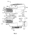
- Figure 2 is a front perspective view of one of the receptacle connectors shown in Figure 1 ;
- Figure 3 is a side view of the electrical connector assembly
- Figure 4 is a front perspective view from an underside of an alternative electrical connector assembly showing a cage member and a plurality of receptacle connectors;
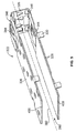
- Figure 5 is a perspective view of a separator member for the cage member shown in Figure 1 and/or Figure 4 ;
- FIG 6 is a front perspective view of the cage member shown in Figure 4 less the receptacle connectors.
- Figure 7 is a perspective view of a pluggable module for receipt within the cage members and for interconnection with the receptacle connectors.
- an electrical connector assembly is provided with a shielding cage member having an upper port and a lower port configured to receive pluggable modules therein.
- the cage member has a front mating face that has openings to receive the pluggable modules.
- the cage member has side walls along the sides of the upper and lower ports and a separator member extending between the side walls between the upper and lower ports.
- the separator member has an upper plate and a lower plate with a channel therebetween.
- An RF absorber is positioned within the channel that reduces an amount of EMI emitted from the channel.
- an electrical connector assembly including a shielding cage member having a port configured to receive a pluggable module therein.
- the cage member has a front mating face and a rear opposite the front mating face.
- the cage member has side walls extending between the front mating face and the rear.
- a receptacle connector is received in the port proximate to the rear.
- the receptacle connector is configured to be electrically connected to the pluggable module, wherein EMI propagates from the receptacle connector in a direction toward the front mating interface.
- An RF absorber is mounted within the cage member that has an absorbing surface oriented parallel to the direction of EMI propagation through the channel. The RF absorber reduces an amount of EMI emitted from the cage member.
- an electrical connector assembly including a shielding cage member configured to receive a pluggable module therein.
- the cage member has a plurality of walls defining the cage member.
- a receptacle connector is received in the cage member.
- the receptacle connector is configured to be electrically connected to the pluggable module.
- An RF absorber applied to one or more of the walls of the cage member that reduces an amount of EMI emitted from the cage member.
- FIG 1 is a front perspective view of an electrical connector assembly 100 formed in accordance with an exemplary embodiment.
- the electrical connector assembly 100 includes a cage member 102 and a receptacle connector 104 received in the cage member 102.
- Pluggable modules 106 (shown in Figure 7 ) are configured to be loaded into the cage member 102 for mating with the receptacle connector 104.
- the receptacle connector 104 is intended for placement on a circuit board, such as a motherboard, and is arranged within the cage member 102 for mating engagement with the pluggable modules 106.
- the cage member 102 is a shielded, stamped and formed cage member that includes a plurality of shielded walls 108 that define multiple ports 110, 112 for receipt of the pluggable modules 106.
- the port 110 defines an upper port positioned above the port 112 and may be referred to hereinafter as upper port 110.
- the port 112 defines a lower port positioned below the port 110 and may be referred to hereinafter as lower port 112. Any number of ports may be provided in alternative embodiments.
- the cage member 102 includes the ports 110, 112 arranged in a single column. However, the cage member 102 may include multiple columns of ports 110, 112 in alternative embodiments.
- the cage member 102 includes a top wall 114, a lower wall 116, a rear wall 117 and side walls 118, 120, which together define the general enclosure for the cage member 102.
- the cage member 102 is subdivided by a center separator member 122 to define the upper and lower ports 110, 112.
- the separator member 122 extends between the side walls 118, 120.
- the separator member 122 has a front wall 124 with an upper plate 126 (shown in Figure 3 ) and a lower plate 128 extending rearward from the front wall 124.
- the separator member 122 is retained in place by tabs 130, which extend from side edges 132, 134 of the upper and lower plates 126, 128, and which extend through the side walls 118, 120.
- the cage member 102 has numerous features allowing the grounding of the cage member 102 to a motherboard and/or a further panel.
- the lower wall 116 and side walls 118, 120 include press fit pins 138 extending therefrom that are configured to be received in plated ground vias of the motherboard to electrically ground the cage member 102 to the ground plane of the motherboard.
- the press fit pins 138 are profiled to both mechanically hold the cage member 102 to the motherboard as well as to ground the cage member 102 thereto.
- the lower wall 116 may include similar press fit pins or other features to provide grounding of the cage member 102 to the motherboard.
- the cage member 102 may include a plurality of resilient tabs profiled to engage an edge of an opening through which the cage member 102 is inserted, such as an opening in a panel or chassis.
- the separator member 122 includes latches 144 adjacent a front edge thereof for securing the pluggable module 106 to the cage member 102.
- the latches 144 have latch openings 146 for latching engagement with the pluggable module 106.
- the latches 144 are deflectable and are stamped from the upper and lower plates 126, 128.
- the lower wall 116 includes an opening 150 therethrough.
- the receptacle connector 104 is received in the opening 150.
- the receptacle connector 104 is accessible through the lower port 112 and the upper port 110.
- the separator member 122 does not extend to the rear wall 117, but rather stops short of the rear wall 117 to provide a space for the receptacle connector 104 to be loaded into the upper port 110.
- FIG. 2 is a front perspective view of the receptacle connector 104.
- the receptacle connector 104 includes a housing 160 defined by an upstanding body portion 162 having side walls 164, 166, a lower face 168 configured to be mounted to the motherboard, and a mating face 170.
- Upper and lower extension portions 172 and 174 extend from the body portion 162 to define the mating face 170.
- a recessed face 176 is defined between the upper and lower extensions 172, 174 at the front face of the body portion 162.
- Circuit card receiving slots 180 and 182 extend inwardly from the mating face 170 of each of the respective upper and lower extensions 172, 174, and extend inwardly to the housing body 160.
- the circuit card receiving slots 180, 182 are configured to receive a card edge of the pluggable module 106 (shown in Figure 7 ).
- a plurality of contacts 184 are held by the housing 160 and are exposed within the circuit card receiving slot 180 for mating with the corresponding pluggable module 106.
- the contacts 184 extend from the lower face 168 and are terminated to the motherboard.
- the ends of the contacts 184 may constitute pins that are loaded into plated vias of the motherboard.
- the contacts 184 may be terminated to the motherboard in another manner, such as by surface mounting to the motherboard.
- a plurality of contacts 186 are held by the housing 160 and are exposed within the circuit card receiving slot 182 for mating with the corresponding pluggable module 106.
- the contacts 186 extend from the lower face 168 and are terminated to the motherboard.
- Figure 3 is a side view of the electrical connector assembly 100.
- the receptacle connector 104 is illustrated loaded into the cage member 102.
- the upper and lower extension portions 172 and 174 are aligned within the upper and lower ports 110, 112.
- the separator member 122 is aligned with the recessed face 176.
- the contacts 184, 186 function as an antenna and radiate energy when the contacts 184, 186 are excited with energy, such as during signal transmission. Such energy is radiated through the cage member 102, including through the separator member 122.
- the separator member 122 includes a channel 190 defined between the upper and lower plates 126, 128.
- the channel 190 is elongated and extends along a longitudinal axis 192 generally from the receptacle connector 104 to the front wall 124.
- the channel 190 is open at the back end of the separator member 122.
- the channel 190 extends to the front wall 124.
- the latches 144 may be at least partially deflected into the channel 190 when the pluggable modules 106 (shown in Figure 7 ) are loaded into the ports 110, 112. Portions of the pluggable modules 106 may be at least partially received in the channel 190 when the pluggable modules 106 are loaded into the ports 110, 112.
- the channel 190 defines a space that allows the latches 144 and/or portions of the pluggable modules 106 to extend into during use.
- the upper and lower plates 126, 128 are spaced apart to accommodate the latches 144 and/or portions of the pluggable modules 106.
- the electrical connector assembly 100 includes a light pipe (LP) structure 196 that includes one or more light pipes.
- the light pipe structure 196 is routed through the channel 190 to the front wall 124.
- the light pipe structure 190 transmits light that may originate from light emitting diodes (LEDs) on the motherboard mounted proximate to the receptacle connector 104.
- the light is transmitted by the light pipe structure 196 from the LEDs to a remote location that is viewable or detectable by an operator.
- the light indicates a condition of the electrical and/or optical connection between the pluggable module 106 (shown in Figure 7 ) and the receptacle connector 104.
- the condition may relate to a quality of transmission between the pluggable module 106 (shown in Figure 7 ) and the receptacle connector 104.
- the status indication may be a colored light (e.g. green for high quality transmission, red for poor transmission or to indicate a disconnection).
- the status indication may be a light that flashes or blinks at a predetermined frequency.
- the receptacle connector 104 generates electric fields which are propagated through the cage member 102.
- the electric fields are propagated in the general direction of the longitudinal axis 192 of the channel 190.
- the energy is propagated down the channel 190 along the longitudinal axis 192 toward the front wall 124.
- the contacts 184, 186 are one source of such electric fields, which are radiated outward and down the channel 190.
- the walls of the cage member 102 being metal, serve to stop most EMI leakage from the cage member 102. However, there are portions of the cage member 102 which are susceptible to EMI leakage.
- EMI leakage may exist at the front wall 124, where the light pipe openings extend through the front wall 124 and/or at the openings around the latches 144 and/or at the seam between the separator member 122 and the cage member 102.
- the EMI propagates down the channel 190 along the longitudinal axis 192 and is leaked through such areas.
- the electrical connector assembly 100 includes RF absorbers 200 positioned within the channel 190 to reduce or even eliminate EMI leakage from the channel 190.
- the RF absorbers 200 are manufactured from an EMI absorbent material and reduce the amount of energy propagated through the cage member 102, particularly through the channel 190 and the walls defining the channel 190.
- the RF absorbers 200 reduce an amount of EMI emitted from the channel 190, such as through the front wall 124 and/or through the openings surrounding the latches 144 at the front edges of the upper and lower plates 126, 128.
- the RF absorbers 200 eliminate substantially all EMI leakage from the channel 190.
- the RF absorbers 200 are manufactured from a material having a high relative permeability to absorb EMI and limit the total radiated power from the channel 190.
- the RF absorbers 200 effectively increase the impedance of the channel 190, reflecting some energy upon entry of the energy into the channel 190, and absorbing the energy that penetrates the channel 190.
- the RF absorbers 200 reduce energy reflections off of the conductive ground planes defined by the upper and lower plates 126, 128.
- the efficiency of the RF absorbers 200 may depend on the formulation and application (thickness, relative permeability, size, location, and the like) of the RF absorbers 200.
- the RF absorbers 200 comprise thin, magnetically loaded elastomeric sheets.
- the RF absorbers 200 may be manufactured from various materials, such as rubber, nitrile, silicon, viton, neoprene, hypolan, urethane, or other elastomeric materials.
- the RF absorbers 200 may have magnetic fillers included within the elastomeric material, such as a carbonyl iron powder, an iron silicide, or other magnetic fillers.
- the type of material within the RF absorbers 200 may be selected to target EMI at different frequencies.
- the RF absorber 200 may be a Q-Zorb tm material, commercially available from Laird Technologies.
- the thickness of the RF absorbers 200 may be selected to control the amount of EMI reduction. For example, different thicknesses of the RF absorbers 200 may be used to target energy at different frequencies.
- the RF absorbers 200 are relatively thin, such that the RF absorbers 200 do not fill too much of the space of the channel 190, such as to maintain a space for the light pipe structure 196 and/or an airflow path through the channel 190.
- the RF absorbers 200 are approximately 1.0 mm thick. Other thicknesses are possible in alternative embodiments.
- the RF absorber 200 takes up less than half a total volume of the channel 190.
- the RF absorber may take up less than 10% of the volume of the channel 190.
- the RF absorber 200 may take up the entire volume of the channel 190.
- the positioning of the RF absorbers 200 within the channel 190 may be selected to control the amount of EMI reduction.
- the RF absorbers 200 are positioned in close proximity to the receptacle connector 104, which is the source of the electric fields.
- the RF absorbers 200 are positioned at the rear end of the separator member 122.
- the RF absorbers 200 are positioned along the interior faces of the upper and lower plates 126, 128 (e.g. the surfaces that face the channel 190).
- the RF absorbers 200 extend generally parallel to the longitudinal axis 192 and the direction of electric field propagation from the receptacle connector 104.
- the RF absorbers 200 thus extend generally parallel to the direction of propagation of the energy through the channel 190.
- the RF absorbers 200 thus constitute surface wave absorbers, which are oriented parallel to the direction of EMI propagation.
- the RF absorbers 200 may have adhesive backings that allow the RF absorbers 200 to be applied to the interior surfaces of the upper and lower plates 126, 128.
- Alternative securing means may be used in alternative embodiments to secure the RF absorbers 200 to the upper and lower plates 126, 128.
- the RF absorbers 200 may be positioned in different locations in alternative embodiments.
- the RF absorbers 200 may be positioned along the interior faces of the side walls 118, 120 (shown in Figure 1 ) within the channel 190.
- the RF absorbers 200 may be positioned at the front wall 124 and/or covering the openings surrounding the latches 144.
- the RF absorber 200 may be thicker and may be positioned within the channel 190 to substantially or entirely fill an area of the channel 190, such as the area identified as area 202, thus functioning as a plug.
- the area 202 may be positioned at a different location along the channel 190 in alternative embodiments.
- the area 202 may be longer or shorter in alternative embodiments, filling a larger or smaller volume of the channel 190.
- the RF absorber 200 may be molded around the light pipe structure 196 and fill the area of the channel 190, but still allow the light pipe structure 196 to pass therethrough.
- FIG 4 is a front perspective view from an underside of an alternative electrical connector assembly 300 showing a cage member 302 and a plurality of the receptacle connectors 104.
- Pluggable modules 106 (shown in Figure 7 ) are configured to be loaded into the cage member 302 for mating with the receptacle connector 104.
- the cage member 302 is a shielded, stamped and formed cage member that includes a plurality of exterior shielded walls 304 and a plurality of interior shielded walls 306 defining the cage member 302.
- the cage member 302 differs from the cage member 102 (shown in Figure 1 ) in that the cage member 302 includes more ports.
- the cage member 302 includes a plurality of upper ports 310 and a plurality of lower ports 312. While four columns of ports 310, 312 are shown, it is realized that any number of columns of ports may be provided in alternative embodiments.
- the exterior shielded walls 304 includes a top wall 314, a lower wall 316, a rear wall 317 and side walls 318, 320, which together define the general enclosure for the cage member 302.
- the interior shielded walls 306 include separator members 322 between the rows of ports 310, 312 and divider walls 324 between the columns of ports 310, 312.
- the separator members 322 extend between one of the side walls 318, 320 and one of the divider walls 324 or between adjacent ones of the divider walls 324.
- FIG 5 is a perspective view of one of the separator members 322, which may be identical to the separator member 122 (shown in Figure 1 ).
- the separator member 322 is stamped and formed from a metal piece into a U-shaped structure.
- the separator member 322 has a front wall 325 with an upper plate 326 and a lower plate 328 extending rearward from the front wall 325.
- the separator member 322 includes tabs 330 extending therefrom that engage the corresponding side walls 318, 320 or divider walls 324 (shown in Figure 4 ).
- the separator member 322 includes latches 344 adjacent a front edge thereof for securing the pluggable module 106 (shown in Figure 7 ) to the cage member 302.
- the latches 344 have latch openings 346 for latching engagement with the pluggable module 106.
- the latches 344 are deflectable and are stamped from the upper and lower plates 326, 328.
- the separator member 322 includes a channel 390 defined between the upper and lower plates 326, 328.
- the channel 390 is elongated and extends along a longitudinal axis 392 between the open rear end and the front wall 325.
- the latches 344 may be at least partially deflected into the channel when the pluggable modules 106 are loaded into the ports 310, 312 (shown in Figure 4 ). Portions of the pluggable modules 106 may be at least partially received in the channel 390 when the pluggable modules 106 are loaded into the ports 310, 312.
- the channel 390 defines a space that allows the latches 344 and/or portions of the pluggable modules 106 to extend into during use.
- the upper and lower plates 326, 328 are spaced apart to accommodate the latches 344 and/or portions of the pluggable modules 106.
- the electrical connector assembly 300 includes RF absorbers 400 positioned within the channel 390 to reduce or even substantially eliminate EMI leakage from the channel 390.
- the RF absorbers 400 are positioned at the rear end of the separator member 322. In the illustrated embodiment, the RF absorbers 400 are positioned along the interior faces of the upper and lower plates 326, 328 (e.g. the surfaces that face the channel 390). The RF absorbers 400 extend generally parallel to the longitudinal axis 392.
- the RF absorbers 400 may have adhesive backings that allow the RF absorbers 400 to be applied to the interior surfaces of the upper and lower plates 326, 328.
- Alternative securing means may be used in alternative embodiments to secure the RF absorbers 400 to the upper and lower plates 326, 328.
- the RF absorbers 400 may be positioned in different locations in alternative embodiments.
- Figure 6 is a front perspective view of the cage member 302 less the receptacle connectors 104 (shown in Figure 4 ).
- the separator members 322 are connected to the corresponding walls 318, 320, 324.
- the separator members 322 are electrically connected to the other walls 304, 306 to provide shielding between the upper and lower ports 310, 312.
- Light pipe structures 196 (shown in Figure 3 ) may be held within the channels 390.
- the RF absorbers 400 reduce EMI leakage from the separator members 322 by absorbing energy propagated down the channel 390.
- FIG 7 illustrates a pluggable module 106 for use with the electrical connector assemblies 100, 300 (shown in Figures 1 and 4 ).
- the pluggable module 106 constitutes a small form-factor pluggable (SFP) module having a circuit card 402 at a mating end 403 thereof for interconnection into the slots 180, 182 (shown in Figure 2 ) and into interconnection with the contacts 184 or 186 therein.
- the pluggable module 106 would further include an electrical interconnection within the module to an interface at end 404, such as a copper interface in the way of a modular jack, or to a fiber optic connector for further interfacing.
- the pluggable module 106 would also include grounding tabs 406, 408, and a raised embossment 410.
- the embossment 410 would latch into the triangular shaped opening of the latch 144 (shown in Figure 1 ) or latch 344 (shown in Figure 5 ). This allows for easy extraction of the pluggable module 106 as the latches 144, 344 are accessible from the front end of the corresponding cage member 102 or 302 (shown in Figure 4 ).
- Other types of pluggable modules or transceivers may be utilized in alternative embodiments.
Landscapes
- Details Of Connecting Devices For Male And Female Coupling (AREA)
- Shielding Devices Or Components To Electric Or Magnetic Fields (AREA)
Abstract
An electrical connector assembly (100) is provided with a shielding cage member (102) having an upper port (110) and a lower port (112) configured to receive pluggable modules therein. The cage member (102) has a front mating face that has openings to receive the pluggable modules. The cage member (102) has side walls (118, 120) along the sides of the upper and lower ports (110, 112) and a separator member (122) extending between the side walls (118, 120) between the upper and lower ports (110, 112). The separator member (122) has an upper plate and a lower plate (128) with a channel therebetween. An RF absorber is positioned within the channel that reduces an amount of EMI emitted from the channel.
Description
- The subject matter herein relates generally to electronic connector assemblies and, more specifically, to connector systems for pluggable electronic modules, such as transceiver modules, for high speed fiber optical and copper communications.
- It is known to provide a metal cage with a plurality of ports, whereby transceiver modules are pluggable therein. It is desirable to increase the port density associated with the network connection, such as, for example, switch boxes, cabling patch panels, wiring closets, and computer I/O. Several pluggable module designs and standards have been introduced in which a pluggable module plugs into a receptacle which is electronically connected to a host circuit board. One such standard that has been promulgated and accepted in the industry is referred to as the small form factor pluggable (SFP) standard which specifies an enclosure height of 9.8 mm and a width of 13.5 mm and a minimum of 20 electrical input/output connections. Such pluggable modules or transceivers provide an interface between a computer and a data communication network such as Ethernet, InfiniBand, Fiber Channel or Serial Attach SCSI.
- It is also desirable to increase the operating frequency of the network connection. For example, applications are quickly moving to the multi-gigabit realm. Electrical connector systems that are used at increased operating speeds present a number of design problems, particularly in applications in which data transmission rates are high, e.g. in the range above 10 Gbps (Gigabits/second). Of particular concern is reducing electromagnetic interference (EMI) emissions. Due to government regulations, there is a need not only to minimize the EMI emissions of the module, but also to contain the EMI emissions of the host system in which the module is mounted regardless of whether a module is plugged in to the receptacle.
- In conventional designs, EMI shielding is achieved by using a shielded metal cage surrounding the receptacles. However, as the speeds of the network connections increase, the EMI shielding provided by conventional cages is proving to be inadequate. Therefore, the problem to be solved is a connection system design that conforms to the SFP standard while minimizing EMI emissions, including to reduce EMI emissions from electrical connectors other than SFP type connectors.
- A solution is provided by an electrical connector assembly with a shielding cage member having an upper port and a lower port configured to receive pluggable modules therein. The cage member has a front mating face that has openings to receive the pluggable modules. The cage member has side walls along the sides of the upper and lower ports and a separator member extending between the side walls between the upper and lower ports. The separator member has an upper plate and a lower plate with a channel therebetween. A radio frequency (RF) absorber is positioned within the channel that reduces an amount of EMI emitted from the channel.
- The invention will now be described by way of example with reference to the accompanying drawings in which:
-
Figure 1 is a front perspective view of an electrical connector assembly formed in accordance with an exemplary embodiment showing a cage member and a receptacle connector; -
Figure 2 is a front perspective view of one of the receptacle connectors shown inFigure 1 ; -
Figure 3 is a side view of the electrical connector assembly; -
Figure 4 is a front perspective view from an underside of an alternative electrical connector assembly showing a cage member and a plurality of receptacle connectors; -
Figure 5 is a perspective view of a separator member for the cage member shown inFigure 1 and/orFigure 4 ; -
Figure 6 is a front perspective view of the cage member shown inFigure 4 less the receptacle connectors; and -
Figure 7 is a perspective view of a pluggable module for receipt within the cage members and for interconnection with the receptacle connectors. - In one embodiment, an electrical connector assembly is provided with a shielding cage member having an upper port and a lower port configured to receive pluggable modules therein. The cage member has a front mating face that has openings to receive the pluggable modules. The cage member has side walls along the sides of the upper and lower ports and a separator member extending between the side walls between the upper and lower ports. The separator member has an upper plate and a lower plate with a channel therebetween. An RF absorber is positioned within the channel that reduces an amount of EMI emitted from the channel.
- In another embodiment, an electrical connector assembly is provided including a shielding cage member having a port configured to receive a pluggable module therein. The cage member has a front mating face and a rear opposite the front mating face. The cage member has side walls extending between the front mating face and the rear. A receptacle connector is received in the port proximate to the rear. The receptacle connector is configured to be electrically connected to the pluggable module, wherein EMI propagates from the receptacle connector in a direction toward the front mating interface. An RF absorber is mounted within the cage member that has an absorbing surface oriented parallel to the direction of EMI propagation through the channel. The RF absorber reduces an amount of EMI emitted from the cage member.
- In a further embodiment, an electrical connector assembly is provided including a shielding cage member configured to receive a pluggable module therein. The cage member has a plurality of walls defining the cage member. A receptacle connector is received in the cage member. The receptacle connector is configured to be electrically connected to the pluggable module. An RF absorber applied to one or more of the walls of the cage member that reduces an amount of EMI emitted from the cage member.
-
Figure 1 is a front perspective view of anelectrical connector assembly 100 formed in accordance with an exemplary embodiment. Theelectrical connector assembly 100 includes acage member 102 and areceptacle connector 104 received in thecage member 102. Pluggable modules 106 (shown inFigure 7 ) are configured to be loaded into thecage member 102 for mating with thereceptacle connector 104. Thereceptacle connector 104 is intended for placement on a circuit board, such as a motherboard, and is arranged within thecage member 102 for mating engagement with thepluggable modules 106. - The
cage member 102 is a shielded, stamped and formed cage member that includes a plurality of shieldedwalls 108 that definemultiple ports pluggable modules 106. Theport 110 defines an upper port positioned above theport 112 and may be referred to hereinafter asupper port 110. Theport 112 defines a lower port positioned below theport 110 and may be referred to hereinafter aslower port 112. Any number of ports may be provided in alternative embodiments. In the illustrated embodiment, thecage member 102 includes theports cage member 102 may include multiple columns ofports - The
cage member 102 includes atop wall 114, alower wall 116, arear wall 117 andside walls cage member 102. Thecage member 102 is subdivided by acenter separator member 122 to define the upper andlower ports separator member 122 extends between theside walls separator member 122 has afront wall 124 with an upper plate 126 (shown inFigure 3 ) and alower plate 128 extending rearward from thefront wall 124. Theseparator member 122 is retained in place bytabs 130, which extend fromside edges lower plates side walls - The
cage member 102 has numerous features allowing the grounding of thecage member 102 to a motherboard and/or a further panel. Thelower wall 116 andside walls press fit pins 138 extending therefrom that are configured to be received in plated ground vias of the motherboard to electrically ground thecage member 102 to the ground plane of the motherboard. Thepress fit pins 138 are profiled to both mechanically hold thecage member 102 to the motherboard as well as to ground thecage member 102 thereto. Thelower wall 116 may include similar press fit pins or other features to provide grounding of thecage member 102 to the motherboard. Around the perimeter of thecage member 102 towards the front edge thereof, thecage member 102 may include a plurality of resilient tabs profiled to engage an edge of an opening through which thecage member 102 is inserted, such as an opening in a panel or chassis. - The
separator member 122 includeslatches 144 adjacent a front edge thereof for securing thepluggable module 106 to thecage member 102. Thelatches 144 havelatch openings 146 for latching engagement with thepluggable module 106. Thelatches 144 are deflectable and are stamped from the upper andlower plates - The
lower wall 116 includes anopening 150 therethrough. Thereceptacle connector 104 is received in theopening 150. Thereceptacle connector 104 is accessible through thelower port 112 and theupper port 110. Theseparator member 122 does not extend to therear wall 117, but rather stops short of therear wall 117 to provide a space for thereceptacle connector 104 to be loaded into theupper port 110. -
Figure 2 is a front perspective view of thereceptacle connector 104. Thereceptacle connector 104 includes ahousing 160 defined by anupstanding body portion 162 havingside walls lower face 168 configured to be mounted to the motherboard, and amating face 170. Upper andlower extension portions body portion 162 to define themating face 170. A recessedface 176 is defined between the upper andlower extensions body portion 162. - Circuit
card receiving slots mating face 170 of each of the respective upper andlower extensions housing body 160. The circuitcard receiving slots Figure 7 ). A plurality ofcontacts 184 are held by thehousing 160 and are exposed within the circuitcard receiving slot 180 for mating with the correspondingpluggable module 106. Thecontacts 184 extend from thelower face 168 and are terminated to the motherboard. For example, the ends of thecontacts 184 may constitute pins that are loaded into plated vias of the motherboard. Alternatively, thecontacts 184 may be terminated to the motherboard in another manner, such as by surface mounting to the motherboard. A plurality ofcontacts 186 are held by thehousing 160 and are exposed within the circuitcard receiving slot 182 for mating with the correspondingpluggable module 106. Thecontacts 186 extend from thelower face 168 and are terminated to the motherboard. -
Figure 3 is a side view of theelectrical connector assembly 100. Thereceptacle connector 104 is illustrated loaded into thecage member 102. The upper andlower extension portions lower ports separator member 122 is aligned with the recessedface 176. Thecontacts contacts cage member 102, including through theseparator member 122. - The
separator member 122 includes achannel 190 defined between the upper andlower plates channel 190 is elongated and extends along alongitudinal axis 192 generally from thereceptacle connector 104 to thefront wall 124. Thechannel 190 is open at the back end of theseparator member 122. Thechannel 190 extends to thefront wall 124. Thelatches 144 may be at least partially deflected into thechannel 190 when the pluggable modules 106 (shown inFigure 7 ) are loaded into theports pluggable modules 106 may be at least partially received in thechannel 190 when thepluggable modules 106 are loaded into theports channel 190 defines a space that allows thelatches 144 and/or portions of thepluggable modules 106 to extend into during use. The upper andlower plates latches 144 and/or portions of thepluggable modules 106. - In an exemplary embodiment, the
electrical connector assembly 100 includes a light pipe (LP)structure 196 that includes one or more light pipes. Thelight pipe structure 196 is routed through thechannel 190 to thefront wall 124. Thelight pipe structure 190 transmits light that may originate from light emitting diodes (LEDs) on the motherboard mounted proximate to thereceptacle connector 104. The light is transmitted by thelight pipe structure 196 from the LEDs to a remote location that is viewable or detectable by an operator. The light indicates a condition of the electrical and/or optical connection between the pluggable module 106 (shown inFigure 7 ) and thereceptacle connector 104. The condition may relate to a quality of transmission between the pluggable module 106 (shown inFigure 7 ) and thereceptacle connector 104. For example, the status indication may be a colored light (e.g. green for high quality transmission, red for poor transmission or to indicate a disconnection). The status indication may be a light that flashes or blinks at a predetermined frequency. - The
receptacle connector 104 generates electric fields which are propagated through thecage member 102. The electric fields are propagated in the general direction of thelongitudinal axis 192 of thechannel 190. The energy is propagated down thechannel 190 along thelongitudinal axis 192 toward thefront wall 124. Thecontacts channel 190. The walls of thecage member 102, being metal, serve to stop most EMI leakage from thecage member 102. However, there are portions of thecage member 102 which are susceptible to EMI leakage. For example, EMI leakage may exist at thefront wall 124, where the light pipe openings extend through thefront wall 124 and/or at the openings around thelatches 144 and/or at the seam between theseparator member 122 and thecage member 102. The EMI propagates down thechannel 190 along thelongitudinal axis 192 and is leaked through such areas. In an exemplary embodiment, theelectrical connector assembly 100 includesRF absorbers 200 positioned within thechannel 190 to reduce or even eliminate EMI leakage from thechannel 190. - The RF absorbers 200 are manufactured from an EMI absorbent material and reduce the amount of energy propagated through the
cage member 102, particularly through thechannel 190 and the walls defining thechannel 190. The RF absorbers 200 reduce an amount of EMI emitted from thechannel 190, such as through thefront wall 124 and/or through the openings surrounding thelatches 144 at the front edges of the upper andlower plates RF absorbers 200 eliminate substantially all EMI leakage from thechannel 190. The RF absorbers 200 are manufactured from a material having a high relative permeability to absorb EMI and limit the total radiated power from thechannel 190. The RF absorbers 200 effectively increase the impedance of thechannel 190, reflecting some energy upon entry of the energy into thechannel 190, and absorbing the energy that penetrates thechannel 190. The RF absorbers 200 reduce energy reflections off of the conductive ground planes defined by the upper andlower plates RF absorbers 200 may depend on the formulation and application (thickness, relative permeability, size, location, and the like) of theRF absorbers 200. - In an exemplary embodiment, the
RF absorbers 200 comprise thin, magnetically loaded elastomeric sheets. The RF absorbers 200 may be manufactured from various materials, such as rubber, nitrile, silicon, viton, neoprene, hypolan, urethane, or other elastomeric materials. The RF absorbers 200 may have magnetic fillers included within the elastomeric material, such as a carbonyl iron powder, an iron silicide, or other magnetic fillers. The type of material within theRF absorbers 200 may be selected to target EMI at different frequencies. In an exemplary embodiment, theRF absorber 200 may be a Q-Zorbtm material, commercially available from Laird Technologies. - The thickness of the
RF absorbers 200 may be selected to control the amount of EMI reduction. For example, different thicknesses of theRF absorbers 200 may be used to target energy at different frequencies. In an exemplary embodiment, theRF absorbers 200 are relatively thin, such that theRF absorbers 200 do not fill too much of the space of thechannel 190, such as to maintain a space for thelight pipe structure 196 and/or an airflow path through thechannel 190. In the illustrated embodiment, theRF absorbers 200 are approximately 1.0 mm thick. Other thicknesses are possible in alternative embodiments. In an exemplary embodiment, theRF absorber 200 takes up less than half a total volume of thechannel 190. Optionally, the RF absorber may take up less than 10% of the volume of thechannel 190. Alternatively, where air flow is not a consideration, theRF absorber 200 may take up the entire volume of thechannel 190. - The positioning of the
RF absorbers 200 within thechannel 190 may be selected to control the amount of EMI reduction. In an exemplary embodiment, theRF absorbers 200 are positioned in close proximity to thereceptacle connector 104, which is the source of the electric fields. For example, theRF absorbers 200 are positioned at the rear end of theseparator member 122. In the illustrated embodiment, theRF absorbers 200 are positioned along the interior faces of the upper andlower plates 126, 128 (e.g. the surfaces that face the channel 190). The RF absorbers 200 extend generally parallel to thelongitudinal axis 192 and the direction of electric field propagation from thereceptacle connector 104. The RF absorbers 200 thus extend generally parallel to the direction of propagation of the energy through thechannel 190. The RF absorbers 200 thus constitute surface wave absorbers, which are oriented parallel to the direction of EMI propagation. - Optionally, the
RF absorbers 200 may have adhesive backings that allow theRF absorbers 200 to be applied to the interior surfaces of the upper andlower plates RF absorbers 200 to the upper andlower plates RF absorbers 200 may be positioned along the interior faces of theside walls 118, 120 (shown inFigure 1 ) within thechannel 190. The RF absorbers 200 may be positioned at thefront wall 124 and/or covering the openings surrounding thelatches 144. - In an alternative embodiment, rather than a thin sheet, the
RF absorber 200 may be thicker and may be positioned within thechannel 190 to substantially or entirely fill an area of thechannel 190, such as the area identified asarea 202, thus functioning as a plug. Thearea 202 may be positioned at a different location along thechannel 190 in alternative embodiments. Thearea 202 may be longer or shorter in alternative embodiments, filling a larger or smaller volume of thechannel 190. In such cases where theRF absorber 200 is used as a plug, thelight pipe structure 196 would not be used or would be rerouted within thecage member 102 to allow theRF absorber 200 to be positioned insuch area 202. Alternatively, theRF absorber 200 may be molded around thelight pipe structure 196 and fill the area of thechannel 190, but still allow thelight pipe structure 196 to pass therethrough. -
Figure 4 is a front perspective view from an underside of an alternativeelectrical connector assembly 300 showing acage member 302 and a plurality of thereceptacle connectors 104. Pluggable modules 106 (shown inFigure 7 ) are configured to be loaded into thecage member 302 for mating with thereceptacle connector 104. - The
cage member 302 is a shielded, stamped and formed cage member that includes a plurality of exterior shieldedwalls 304 and a plurality of interior shieldedwalls 306 defining thecage member 302. Thecage member 302 differs from the cage member 102 (shown inFigure 1 ) in that thecage member 302 includes more ports. Thecage member 302 includes a plurality ofupper ports 310 and a plurality oflower ports 312. While four columns ofports - The exterior shielded
walls 304 includes atop wall 314, alower wall 316, arear wall 317 andside walls cage member 302. The interior shieldedwalls 306 includeseparator members 322 between the rows ofports divider walls 324 between the columns ofports separator members 322 extend between one of theside walls divider walls 324 or between adjacent ones of thedivider walls 324. -
Figure 5 is a perspective view of one of theseparator members 322, which may be identical to the separator member 122 (shown inFigure 1 ). Theseparator member 322 is stamped and formed from a metal piece into a U-shaped structure. Theseparator member 322 has afront wall 325 with anupper plate 326 and alower plate 328 extending rearward from thefront wall 325. Theseparator member 322 includestabs 330 extending therefrom that engage thecorresponding side walls Figure 4 ). - The
separator member 322 includeslatches 344 adjacent a front edge thereof for securing the pluggable module 106 (shown inFigure 7 ) to thecage member 302. Thelatches 344 havelatch openings 346 for latching engagement with thepluggable module 106. Thelatches 344 are deflectable and are stamped from the upper andlower plates - The
separator member 322 includes achannel 390 defined between the upper andlower plates channel 390 is elongated and extends along alongitudinal axis 392 between the open rear end and thefront wall 325. Thelatches 344 may be at least partially deflected into the channel when thepluggable modules 106 are loaded into theports 310, 312 (shown inFigure 4 ). Portions of thepluggable modules 106 may be at least partially received in thechannel 390 when thepluggable modules 106 are loaded into theports channel 390 defines a space that allows thelatches 344 and/or portions of thepluggable modules 106 to extend into during use. The upper andlower plates latches 344 and/or portions of thepluggable modules 106. - In an exemplary embodiment, the
electrical connector assembly 300 includesRF absorbers 400 positioned within thechannel 390 to reduce or even substantially eliminate EMI leakage from thechannel 390. The RF absorbers 400 are positioned at the rear end of theseparator member 322. In the illustrated embodiment, theRF absorbers 400 are positioned along the interior faces of the upper andlower plates 326, 328 (e.g. the surfaces that face the channel 390). The RF absorbers 400 extend generally parallel to thelongitudinal axis 392. - Optionally, the
RF absorbers 400 may have adhesive backings that allow theRF absorbers 400 to be applied to the interior surfaces of the upper andlower plates RF absorbers 400 to the upper andlower plates -
Figure 6 is a front perspective view of thecage member 302 less the receptacle connectors 104 (shown inFigure 4 ). Theseparator members 322 are connected to thecorresponding walls separator members 322 are electrically connected to theother walls lower ports Figure 3 ) may be held within thechannels 390. The RF absorbers 400 reduce EMI leakage from theseparator members 322 by absorbing energy propagated down thechannel 390. -
Figure 7 illustrates apluggable module 106 for use with theelectrical connector assemblies 100, 300 (shown inFigures 1 and4 ). In the illustrated embodiment, thepluggable module 106 constitutes a small form-factor pluggable (SFP) module having acircuit card 402 at amating end 403 thereof for interconnection into theslots 180, 182 (shown inFigure 2 ) and into interconnection with thecontacts pluggable module 106 would further include an electrical interconnection within the module to an interface atend 404, such as a copper interface in the way of a modular jack, or to a fiber optic connector for further interfacing. Thepluggable module 106 would also include groundingtabs embossment 410. Theembossment 410 would latch into the triangular shaped opening of the latch 144 (shown inFigure 1 ) or latch 344 (shown inFigure 5 ). This allows for easy extraction of thepluggable module 106 as thelatches corresponding cage member 102 or 302 (shown inFigure 4 ). Other types of pluggable modules or transceivers may be utilized in alternative embodiments.
Claims (10)
- An electrical connector assembly (100) comprising:a shielding cage member (102) having an upper port (110) and a lower port (112) configured to receive pluggable modules (106) therein, the cage member (102) having a front mating face having openings receiving the pluggable modules (106), the cage member (102) having side walls (118, 120) along the sides of the upper and lower ports (110, 112) and a separator member (122) extending between the side walls (118, 120) between the upper and lower ports (110, 112), the separator member (122) having an upper plate (126) and a lower plate (128) with a channel (190) therebetween; andan RF absorber (200) positioned within the channel (190), the RF absorber (200) reducing an amount of EMI emitted from the channel (190).
- The electrical connector assembly (100) of claim 1, wherein the RF absorber (200) comprises a sheet applied to at least one of the upper plate (126) or the lower plate (128).
- The electrical connector assembly (100) of claim 1, wherein the RF absorber (200) constitutes a surface wave absorber arranged generally parallel to a direction of EMI propagation through the separator member (122).
- The electrical connector assembly (100) of claim 1, wherein the RF absorber (200) is fabricated from an elastomeric material.
- The electrical connector assembly (100) of claim 1, wherein the RF absorber (200) comprises a first RF absorber (200) applied to the upper plate (126) and a second RF absorber (200) applied to the lower plate (128), a gap separating the first and second RF absorbers (200).
- The electrical connector assembly (100) of claim 1, wherein the cage member (102) has a rear opposite the front mating face, the channel (190) being elongated between the front mating face and the rear along a longitudinal axis (192), the RF absorber (200) comprises a sheet extending parallel to the longitudinal axis (192).
- The electrical connector assembly (100) of claim 1, wherein the upper plate (126) includes a latch (144) at the front mating face for latching the pluggable module (106) within the upper port (110), the lower plate (128) including a latch (144) at the front mating face for latching the pluggable module (106) within the lower port (112), the RF absorber (200) extending along at least one of the upper plate (126) or lower (128) rearward of the corresponding latch (144).
- The electrical connector assembly (100) of any preceding claim, further comprising a receptacle connector (104) received in the cage member (102), the receptacle connector (104) being accessible through the upper port (110) and the lower port (112), the pluggable modules (106) being electrically connected to the receptacle connector (104).
- The electrical connector assembly (100) of any preceding claim, further comprising a light pipe assembly (196) received in the channel (190).
- The electrical connector assembly (100) of claim 1, wherein the separator member (122) is U-shaped with a front wall (124) between the upper plate (126) and the lower plate (128), the electrical connector assembly (100) further comprising a receptacle connector (104) received in the cage member (102) rearward of the separator member (122), the receptacle connector (104) generating an energy field through the channel (190) in the direction of the front wall (124), the RF absorber (200) extending parallel to the direction of energy propagation.
Applications Claiming Priority (1)
| Application Number | Priority Date | Filing Date | Title |
|---|---|---|---|
| US12/896,611 US8277252B2 (en) | 2010-10-01 | 2010-10-01 | Electrical connector assembly |
Publications (1)
| Publication Number | Publication Date |
|---|---|
| EP2437358A1 true EP2437358A1 (en) | 2012-04-04 |
Family
ID=44719630
Family Applications (1)
| Application Number | Title | Priority Date | Filing Date |
|---|---|---|---|
| EP11183519A Withdrawn EP2437358A1 (en) | 2010-10-01 | 2011-09-30 | Electrical connector assembly |
Country Status (3)
| Country | Link |
|---|---|
| US (1) | US8277252B2 (en) |
| EP (1) | EP2437358A1 (en) |
| CN (1) | CN102447198B (en) |
Cited By (2)
| Publication number | Priority date | Publication date | Assignee | Title |
|---|---|---|---|---|
| WO2014005026A1 (en) * | 2012-06-29 | 2014-01-03 | Amphenol Corporation | Low cost, high performance rf connector |
| GB2533354A (en) * | 2014-12-17 | 2016-06-22 | Etl Systems Ltd | Connector Assembly and related methods and assemblies |
Families Citing this family (29)
| Publication number | Priority date | Publication date | Assignee | Title |
|---|---|---|---|---|
| US8545267B2 (en) * | 2010-10-01 | 2013-10-01 | Tyco Electronics Corporation | Electrical connector assembly |
| US8545268B2 (en) * | 2010-10-01 | 2013-10-01 | Tyco Electronics Corporation | Electrical connector assembly |
| US8469744B2 (en) * | 2011-01-28 | 2013-06-25 | Tyco Electronics Corporation | Electrical connector assembly having airflow channels |
| US8890004B2 (en) * | 2012-01-23 | 2014-11-18 | Tyco Electronics Corporation | Electrical connector assembly with EMI cover |
| US8834205B2 (en) * | 2012-07-19 | 2014-09-16 | Tyco Electronics Corporation | Pluggable module system |
| US8870595B2 (en) * | 2012-07-24 | 2014-10-28 | Tyco Electronics Corporation | Electrical connector assembly having an RF absorber |
| CN105934854B (en) * | 2013-08-16 | 2018-10-23 | 莫列斯有限公司 | Connector with thermal management |
| US9419391B2 (en) | 2013-08-20 | 2016-08-16 | Panduit Corp. | Communication connector |
| US20150072561A1 (en) * | 2013-09-06 | 2015-03-12 | Tyco Electronics Corporation | Cage with emi absorber |
| US9113568B2 (en) | 2013-10-31 | 2015-08-18 | Tyco Electronics Corporation | Cabled backplane system having an electromagnetic radiation absorber |
| EP3100324B1 (en) * | 2014-01-27 | 2020-12-09 | Napatech A/S | Activity diodes, reflective housings and method |
| US9252538B2 (en) * | 2014-02-28 | 2016-02-02 | Tyco Electronics Corporation | Receptacle assembly having a light indicator |
| WO2015148786A1 (en) * | 2014-03-27 | 2015-10-01 | Molex Incorporated | Thermally efficient connector system |
| WO2015164538A1 (en) | 2014-04-23 | 2015-10-29 | Tyco Electronics Corporation | Electrical connector with shield cap and shielded terminals |
| US9391407B1 (en) * | 2015-06-12 | 2016-07-12 | Tyco Electronics Corporation | Electrical connector assembly having stepped surface |
| CN110673277A (en) * | 2015-09-10 | 2020-01-10 | 申泰公司 | Rack mount equipment with high heat dissipation modules and transceiver sockets with increased cooling |
| US9673570B2 (en) * | 2015-09-22 | 2017-06-06 | Te Connectivity Corporation | Stacked cage having different size ports |
| US9608377B1 (en) * | 2015-12-16 | 2017-03-28 | Te Connectivity Corporation | Caged electrical connector assemblies having indicator lights |
| CN107046206B (en) * | 2017-01-23 | 2021-07-20 | 富士康(昆山)电脑接插件有限公司 | Electrical connector |
| CN109346873A (en) * | 2018-09-10 | 2019-02-15 | 深圳市方向电子有限公司 | Connector |
| CN111416239A (en) * | 2019-01-08 | 2020-07-14 | 泰科电子(上海)有限公司 | Leadframes, Electrical Equipment and Isolation Components |
| US10840645B2 (en) * | 2019-02-21 | 2020-11-17 | Te Connectivity Corporation | Light pipe assembly for a receptacle assembly |
| US11011861B1 (en) * | 2019-10-25 | 2021-05-18 | TE Connectivity Services Gmbh | Stacked receptacle connector assembly |
| CN111244668B (en) * | 2020-03-09 | 2025-10-10 | 温州意华接插件股份有限公司 | A high-speed electrical connector |
| CN111509433A (en) * | 2020-04-24 | 2020-08-07 | 东莞立讯技术有限公司 | Connector with a locking member |
| US11650385B2 (en) * | 2021-02-03 | 2023-05-16 | Cisco Technology, Inc. | Optical module cages mounted for optimal density and cooling |
| USD1073616S1 (en) * | 2021-10-28 | 2025-05-06 | Dongguan Luxshare Technologies Co., Ltd | Cage of electrical connector |
| US12308578B2 (en) * | 2022-06-13 | 2025-05-20 | Te Connectivity Solutions Gmbh | Receptacle cage having absorber |
| CN116598823A (en) * | 2023-01-19 | 2023-08-15 | 东莞立讯技术有限公司 | Connector Assembly |
Citations (4)
| Publication number | Priority date | Publication date | Assignee | Title |
|---|---|---|---|---|
| US20070290765A1 (en) * | 2006-06-16 | 2007-12-20 | Inventec Corporation | Connector structure |
| WO2010019332A2 (en) * | 2008-08-15 | 2010-02-18 | 3M Innovative Properties Company | Electrical connector assembly |
| US7704097B1 (en) * | 2009-02-17 | 2010-04-27 | Tyco Electronics Corporation | Connector assembly having an electromagnetic seal element |
| US20100151733A1 (en) * | 2008-12-11 | 2010-06-17 | Cheng Jung Tsou | Connector shielding apparatus and methods |
Family Cites Families (6)
| Publication number | Priority date | Publication date | Assignee | Title |
|---|---|---|---|---|
| US7070446B2 (en) | 2003-08-27 | 2006-07-04 | Tyco Electronics Corporation | Stacked SFP connector and cage assembly |
| WO2005114274A1 (en) * | 2004-05-14 | 2005-12-01 | Molex Incorporated | Light pipe assembly for use with small form factor connector |
| US7037136B1 (en) * | 2005-02-15 | 2006-05-02 | Hon Hai Precision Ind. Co., Ltd. | Connector module |
| US7845975B2 (en) * | 2007-01-30 | 2010-12-07 | Pulse Engineering, Inc. | Low-profile connector assembly and methods |
| US7641515B1 (en) * | 2008-08-21 | 2010-01-05 | Tyco Electronics Corporation | Center plate for a connector assembly |
| US8684765B2 (en) | 2008-10-31 | 2014-04-01 | Tyco Electronics Corporation | Connector assembly including a light pipe assembly |
-
2010
- 2010-10-01 US US12/896,611 patent/US8277252B2/en active Active
-
2011
- 2011-09-30 EP EP11183519A patent/EP2437358A1/en not_active Withdrawn
- 2011-10-08 CN CN201110445224.XA patent/CN102447198B/en active Active
Patent Citations (4)
| Publication number | Priority date | Publication date | Assignee | Title |
|---|---|---|---|---|
| US20070290765A1 (en) * | 2006-06-16 | 2007-12-20 | Inventec Corporation | Connector structure |
| WO2010019332A2 (en) * | 2008-08-15 | 2010-02-18 | 3M Innovative Properties Company | Electrical connector assembly |
| US20100151733A1 (en) * | 2008-12-11 | 2010-06-17 | Cheng Jung Tsou | Connector shielding apparatus and methods |
| US7704097B1 (en) * | 2009-02-17 | 2010-04-27 | Tyco Electronics Corporation | Connector assembly having an electromagnetic seal element |
Cited By (7)
| Publication number | Priority date | Publication date | Assignee | Title |
|---|---|---|---|---|
| WO2014005026A1 (en) * | 2012-06-29 | 2014-01-03 | Amphenol Corporation | Low cost, high performance rf connector |
| US9022806B2 (en) | 2012-06-29 | 2015-05-05 | Amphenol Corporation | Printed circuit board for RF connector mounting |
| US9225085B2 (en) | 2012-06-29 | 2015-12-29 | Amphenol Corporation | High performance connector contact structure |
| US9583853B2 (en) | 2012-06-29 | 2017-02-28 | Amphenol Corporation | Low cost, high performance RF connector |
| GB2533354A (en) * | 2014-12-17 | 2016-06-22 | Etl Systems Ltd | Connector Assembly and related methods and assemblies |
| GB2533354B (en) * | 2014-12-17 | 2017-09-13 | Etl Systems Ltd | Connector assembly and related methods and assemblies |
| US10454223B2 (en) | 2014-12-17 | 2019-10-22 | Etl Systems Limited | Connector assembly and related methods and assemblies |
Also Published As
| Publication number | Publication date |
|---|---|
| US8277252B2 (en) | 2012-10-02 |
| CN102447198B (en) | 2016-05-11 |
| US20120083156A1 (en) | 2012-04-05 |
| CN102447198A (en) | 2012-05-09 |
Similar Documents
| Publication | Publication Date | Title |
|---|---|---|
| US8277252B2 (en) | Electrical connector assembly | |
| US8545268B2 (en) | Electrical connector assembly | |
| US8545267B2 (en) | Electrical connector assembly | |
| US8870595B2 (en) | Electrical connector assembly having an RF absorber | |
| US8469744B2 (en) | Electrical connector assembly having airflow channels | |
| US8613632B1 (en) | Electrical connector assembly having thermal vents | |
| US10312615B2 (en) | Electrical interconnection system and electrical connectors for the same | |
| US9935403B1 (en) | Pluggable module having cooling channel | |
| US7452216B2 (en) | Transceiver receptacle assembly | |
| US6517382B2 (en) | Pluggable module and receptacle | |
| US9666995B1 (en) | EMI containment cage member | |
| US9666997B1 (en) | Gasket plate for a receptacle assembly of a communication system | |
| US9735481B2 (en) | Daughter card assembly and communication system including the same | |
| US8007318B1 (en) | Shielded integrated connector module | |
| US9825408B2 (en) | Connector module assembly having a gasket plate | |
| US10490952B2 (en) | Receptacle cage member having locating features | |
| US20150072561A1 (en) | Cage with emi absorber | |
| US11005218B2 (en) | Shielding structure for an electrical connector | |
| CN102714379A (en) | Shielded connector | |
| CN104602502A (en) | Cabled backplane system having an electromagnetic radiation absorber | |
| US12308578B2 (en) | Receptacle cage having absorber | |
| CN213660788U (en) | Terminal module, backplane connector and connector assembly |
Legal Events
| Date | Code | Title | Description |
|---|---|---|---|
| PUAI | Public reference made under article 153(3) epc to a published international application that has entered the european phase |
Free format text: ORIGINAL CODE: 0009012 |
|
| AK | Designated contracting states |
Kind code of ref document: A1 Designated state(s): AL AT BE BG CH CY CZ DE DK EE ES FI FR GB GR HR HU IE IS IT LI LT LU LV MC MK MT NL NO PL PT RO RS SE SI SK SM TR |
|
| AX | Request for extension of the european patent |
Extension state: BA ME |
|
| STAA | Information on the status of an ep patent application or granted ep patent |
Free format text: STATUS: THE APPLICATION IS DEEMED TO BE WITHDRAWN |
|
| 18D | Application deemed to be withdrawn |
Effective date: 20121005 |