EP2437349A1 - Display device - Google Patents
Display device Download PDFInfo
- Publication number
- EP2437349A1 EP2437349A1 EP11181185A EP11181185A EP2437349A1 EP 2437349 A1 EP2437349 A1 EP 2437349A1 EP 11181185 A EP11181185 A EP 11181185A EP 11181185 A EP11181185 A EP 11181185A EP 2437349 A1 EP2437349 A1 EP 2437349A1
- Authority
- EP
- European Patent Office
- Prior art keywords
- metal plate
- antenna
- flat
- antennas
- display portion
- Prior art date
- Legal status (The legal status is an assumption and is not a legal conclusion. Google has not performed a legal analysis and makes no representation as to the accuracy of the status listed.)
- Withdrawn
Links
- 239000002184 metal Substances 0.000 claims abstract description 71
- 230000005855 radiation Effects 0.000 claims description 31
- 238000004891 communication Methods 0.000 description 9
- 238000005516 engineering process Methods 0.000 description 6
- 239000000758 substrate Substances 0.000 description 5
- 238000002955 isolation Methods 0.000 description 4
- 230000008878 coupling Effects 0.000 description 3
- 238000010168 coupling process Methods 0.000 description 3
- 238000005859 coupling reaction Methods 0.000 description 3
- 230000002238 attenuated effect Effects 0.000 description 2
- 230000005540 biological transmission Effects 0.000 description 2
- 230000015556 catabolic process Effects 0.000 description 2
- 239000004020 conductor Substances 0.000 description 2
- 238000006731 degradation reaction Methods 0.000 description 2
- 230000000116 mitigating effect Effects 0.000 description 2
- NJPPVKZQTLUDBO-UHFFFAOYSA-N novaluron Chemical compound C1=C(Cl)C(OC(F)(F)C(OC(F)(F)F)F)=CC=C1NC(=O)NC(=O)C1=C(F)C=CC=C1F NJPPVKZQTLUDBO-UHFFFAOYSA-N 0.000 description 2
- 230000000630 rising effect Effects 0.000 description 2
- 230000003247 decreasing effect Effects 0.000 description 1
- 238000010586 diagram Methods 0.000 description 1
- 238000005259 measurement Methods 0.000 description 1
- 238000012986 modification Methods 0.000 description 1
- 230000004048 modification Effects 0.000 description 1
Images






Classifications
-
- H—ELECTRICITY
- H01—ELECTRIC ELEMENTS
- H01Q—ANTENNAS, i.e. RADIO AERIALS
- H01Q1/00—Details of, or arrangements associated with, antennas
- H01Q1/12—Supports; Mounting means
- H01Q1/22—Supports; Mounting means by structural association with other equipment or articles
- H01Q1/2258—Supports; Mounting means by structural association with other equipment or articles used with computer equipment
- H01Q1/2266—Supports; Mounting means by structural association with other equipment or articles used with computer equipment disposed inside the computer
-
- G—PHYSICS
- G09—EDUCATION; CRYPTOGRAPHY; DISPLAY; ADVERTISING; SEALS
- G09F—DISPLAYING; ADVERTISING; SIGNS; LABELS OR NAME-PLATES; SEALS
- G09F9/00—Indicating arrangements for variable information in which the information is built-up on a support by selection or combination of individual elements
-
- H—ELECTRICITY
- H01—ELECTRIC ELEMENTS
- H01Q—ANTENNAS, i.e. RADIO AERIALS
- H01Q1/00—Details of, or arrangements associated with, antennas
- H01Q1/52—Means for reducing coupling between antennas; Means for reducing coupling between an antenna and another structure
- H01Q1/521—Means for reducing coupling between antennas; Means for reducing coupling between an antenna and another structure reducing the coupling between adjacent antennas
-
- H—ELECTRICITY
- H04—ELECTRIC COMMUNICATION TECHNIQUE
- H04L—TRANSMISSION OF DIGITAL INFORMATION, e.g. TELEGRAPHIC COMMUNICATION
- H04L7/00—Arrangements for synchronising receiver with transmitter
- H04L7/04—Speed or phase control by synchronisation signals
Definitions
- the present invention relates to a display device equipped with an antenna device comprising multiple antennas for a wireless LAN.
- MIMO Multiple Input Multiple Output
- Patent JP 2010-004318A discloses an example of applying the MIMO technology. It discloses an antenna device (for example, one shown in FIG. 11 ) which maintains isolation between antennas of two items of radio equipment in a communication device equipped with the two items of radio equipment where near-by or close frequency bandwidths are used.
- An antenna device 101 shown in FIG. 11 includes a first dipole antenna 102 and a second dipole antenna 103 disposed at different sides of an upper edge of a substrate 104.
- the first dipole antenna 102 is composed of radiation elements 102a, 102b symmetrically disposed with respect to a feeding point 105 at a center of the antenna.
- the feeding point 105 is connected through a coaxial cable 106 to a radio circuit (not shown) mounted on the substrate.
- An external conductor of the coaxial cable 106 is connected to ground patterns 107 formed on the substrate.
- the second dipole antenna 103 is composed of radiation elements 103a,103b symmetrically disposed with respect to a feeding point 108 at a center of the antenna.
- the feeding point 108 is connected through a coaxial cable 109 to a radio circuit (not shown) mounted on the substrate.
- An external conductor of a coaxial cable 109 is connected to the ground pattern 107 formed on the substrate 104.
- the radiation elements 102a, 102b of the first dipole antenna 102 and the radiation elements 103a, 103b of the second dipole antenna 103 are disposed orthogonally in relation to each other in an XZ plane. Further, the radiation elements 102a, 102b of the first dipole antenna 102 are disposed, inclined, at an angle (45° in the example shown Fig FIG. 11 ) larger than 0° and smaller than 90°, from a Z-axis direction towards an X-axis direction in the XZ plane.
- the radiation elements 102a,102b and the radiation elements 103a,103b are disposed orthogonally in relation to each other in the XZ plane, polarized waves radiated from the two dipole antennas 102, 103 will cross each other at right angles.
- the two dipole antennas 102,103 are oppositely disposed in contiguity with each other, coupling caused by theses radiation waves can be decreased, thereby providing large isolation.
- the conventional antenna device 101 shown in FIG. 11 was not developed for use in display devices. If the conventional antenna device 101 shown in FIG. 11 is mounted, for example, on either surface of the flat-display panel portion on which the metal plate is provided on the upper and lower surfaces and both sides, radio waves radiated from the radiation elements 102a, 102b and the radiation elements 103a, 103b may be affected by the metal plate.
- the object of the present invention is to provide a display device with an antenna device for a wireless LAN, comprising multiple antennas, which are capable of radiating radio waves to a remote location, without being affected by a metal plate provided in the flat-panel display portion or metal body disposed around, the display device.
- a display device comprises: a flat-panel display portion on upper surface of which a linearly extending metal plate is provided; and an antenna device for a wireless LAN arranged on the upper surface of the flat-panel display portion, wherein the antenna equipment comprises multiple antennas arranged side-by-side on the straight line and arranged in parallel with the metal plate, the multiple antennas being arranged so that preferably a predetermined distance between adjacent said antennas becomes the shortest, and wherein plural apertures are formed at a position corresponding to each antenna of the metal plate.
- the "predetermined distance” is a distance between the adjacent antennas where a ratio (voltage standing wave ratio: VSWR) of a predetermined voltage at an output side to that of an input side is below -20 dB, when a high frequency signal having a predetermined voltage is input from one antenna and the predetermined voltage is derived thereby from the other antenna.
- a ratio voltage standing wave ratio: VSWR
- each of the multiple antennas comprises a tab-like ground plate and a tab-like radiation element rising up or extending from an edge of the ground plate, wherein each of the multiple antennas is arranged so that its radiation element faces towards one said aperture formed in the metal plate.
- the radiation elements of the multiple antennas and the metal plate are arranged on said straight line.
- the antenna device for the wireless LAN since the antenna device for the wireless LAN is arranged on the upper surface of the flat-panel display portion, the antenna equipment is able to radiate the radio waves to a distant or far away location, without being affected by the metal body disposed around the display device.
- the antenna device for the wires LAN is arranged on a lower surface of the flat-panel display portion, when the metal body is used in a pedestal on which the flat-panel display portion is mounted, the antenna device is susceptible to be influenced by the metal body.
- the antenna device for the wireless LAN is arranged on the both sides of the flat-panel display portion, when the display device is disposed in the vicinity of a wall on which the metal body is provided, the antenna device is susceptible to be influenced by the metal body. In contrast, when the antenna device for the wireless LAN is arranged on the upper surface of the flat-panel display portion, such shortcomings will not occur.
- the antenna device comprises multiple antennas arranged side-by-side on the same straight line and arranged parallel with a linearly extending metal plate provided on the upper surface of the flat-panel display.
- the plural apertures are formed at positions, corresponding to each antenna of the metal plate. Therefore, radio waves radiated from each of the multiple antennas are radiated through respective apertures formed in the metal plate provided on the upper surface of the flat-panel display portion. This radiates the radio waves to a distant or far away location, without being affected by the metal plate provided in the flat-panel display portion.
- the provision of the metal plate on the upper surface of the flat-panel display portion contributes to maintaining the mechanical strength of the flat-panel display portion.
- the multiple antennas are arranged so that the antennas are spaced away from each other by a predetermined distance between the antennas adjacent to one another, coupling arising from radio waves radiated from each antenna may be attenuated. This maintains high isolation, thus allowing communication without suffering from degradation of the signal from each antenna.
- a display device 1 shown in FIG. 1 to FIG. 3 is applied to a flat TV set and is useable with a Multiple Input and Multiple Output (MIMO)system which complies with wireless LAN standard "IEEE 802. 11n".
- the display device 1 comprises a flat-panel display portion 10 and an antenna device 20 for a wireless LAN.
- the flat-panel display portion 10 is formed in a substantially rectangular shape, having thickness t in a depth direction (upper and lower direction in FIG. 1 ), with an upper surface 10a, a lower surface 10b, and left and right sides 10c and 10d.
- a linearly extending metal plate 11 is provided along the front end edge.
- the metal plate 11 has portions which protrude upwardly from the upper surface 10a of the flat-panel display portion 10 and is made from a flat rectangular panel.
- the metal panel 11 includes plural (two in the instant embodiment) apertures 12A, 12B each formed at a position corresponding to one antenna 20A, 20B as discussed in detail later.
- the antenna device 20 comprises multiple (two in the instant embodiment) antennas 20A, 20B. As shown in FIG. 1 , the multiple antennas 20A, 20B are arranged side by side on the same straight line and are arranged parallel to the metal plate 11. The multiple antennas 20A, 20B are arranged so as to be spaced apart from each other by a predetermined distance D between the adjacent antennas 20A, 20B.
- the predetermined distance D is a distance between the adjacent antennas, where a ratio (voltage standing wave ratio: VSWR) of a predetermined voltage at an output side to a predetermined voltage at an input side, is below -20 dB, when a high frequency signal having a predetermined voltage is input from one antenna and the predetermined Voltage is derived thereby from the other antenna.
- a transmission performance of the high frequency signal between the adjoined antennas is measured in a trial display device shown in FIG. 7 using the network analyzer.
- the trial display device 51 shown in FIG. 7 includes an antenna device 70 for a wireless LAN on an upper surface 60a of a flat-panel display portion 60.
- a linearly extending metal plate 61 is provided along the front end edge.
- the antenna device 70 comprises a pair of antennas 70A, 70B aligned on a straight line parallel with the metal plate 61. Spacing between the pair of the antennas 70A, 70B is set to a predetermined distance D of which length is determined to be approximately 120mm.
- an aperture 62A, 62B is formed at a position corresponding to each antenna 70A, 70B on the metal plate 61.
- the pair of antennas 70A, 70B are arranged at the center in the depth direction of the upper surface 60a of the flat-panel display portion 60 spaced from the metal plate 61.
- a network analyzer (not shown) is utilized to input a high frequency signal (ranging from about 2.00 GHz to 6.00 GHz) having a predetermined voltage from one of the pair of the antennas 70A,70B.
- the predetermined voltage is derived from the other adjacent antenna (s) 70A, 70B and a ratio (voltage standing wave ratio: VSWR) of the predetermined Voltage at the output side to that at the input side is measured.
- VSWR voltage standing wave ratio
- the predetermined distance D between the pair of the antennas 70A, 70B is approximately 120mm
- the ratio (voltage standing wave ratio: VSWR) of the predetermined Voltage at the output side to that at the input side is -20dB (which is a specification requirement), even for high frequency signals of both 2.4 GHz band and 5 GHz band used for wireless LANs.
- VSWR voltage standing wave ratio
- the antennas 70A, 70B are arranged such that the predetermined distance D becomes the shortest.
- the antenna 20A is a so-called inverted F antenna, and comprises, as shown in FIG. 4 to FIG. 6 , a rectangular and tab-like ground plate 21 and a tab-like radiation element 22 rising or extending up from one side edge of the ground plate 21.
- the antenna 20A is made by stamping and forming a metal plate.
- a core wire 30a of a coaxial cable 30 is soldered to the radiation elements 22, and a braid 30b is soldered to the ground plate 21.
- the coaxial cable 30 is connected to a wireless LAN module 40 to control MIMO communication.
- the multiple antennas 20A, 20B are arranged on the upper surface 10a of the flat-panel display portion 10 so that the radiation elements 22 face the apertures 12A, 12B formed in the metal plate 11, and are arranged on the same straight line with the metal plate 11. That is, the multiple antennas 20A, 20B are arranged so that each radiation element 22 is positioned inside one of the apertures 12A,12B formed in the metal plate 11, and is positioned along the front end edge, in the depth direction, of the upper surface 10a of the flat-panel display portion 10.
- the width L of each aperture 12A, 12B is approximately 65 mm
- the width W of each antenna 20A, 20B is approximately 25 mm
- a distance of both sides of the antenna 20A, 20B is set to be approximately 20 mm.
- the width L of each aperture 12A, 12B has to be approximately 65 mm, when the width W of each antenna 20A, 20B is approximately 25mm.
- a cover member (not shown) covers around the flat-panel display portion 10 and the antenna device 20 for the wireless LAN.
- a high frequency radio wave having either 2.4 GHz band or 5 GHz band is radiated from the both antennas 20A, 20B. More specifically, the high frequency radio wave having either 2.4 GHz band or 5 GHz band is radiated from the radiation elements 22 of both antennas 20A, 20B, towards an access point (not shown) positioned at the forward side (upper side in FIG. 1 ) of the display device, at a radiation angle of ⁇ (see FIG. 10A and FIG. 10B ). Further, when receiving the MIMO, the high frequency radio wave having either 2.4 GHz band or 5 GHz band radiated from the access point is received by the both antennas 20A, 20B.
- the arrangement of the antenna device 20 for the wireless LAN on the upper surface 10A of the flat-panel display portion 10 allows radiation of radio waves far away, without being affected by the metal body placed around the display device 1.
- the antenna device 20 for the wireless LAN is arranged on the lower surface 10b of the flat-panel display portion 10
- the antenna device is susceptible to influence by the metal body.
- the antenna device 20 for the wireless LAN is arranged on one or both sides 10c, 10d of the flat-panel display portion 10
- the antenna device 1 is disposed in the vicinity of a wall on which the metal body is provided
- the antenna device is susceptible to influence by the metal body.
- the antenna device 20 for the wireless LAN is arranged on the upper surface 10a of the flat-panel display portion 10, such drawbacks will not occur.
- the antenna device 20 comprises the multiple antennas 20A, 20B arranged side by side on the same straight line and arranged parallel to the linearly extending metal plate that is provided on the upper surface 10a of the flat-panel display portion 10. At a position of the metal plate 11 corresponding to each antenna 20A, 20B, an aperture 12A,12B is formed. Therefore, radio waves radiated from each of the multiple antennas 20A, 20B are radiated through each aperture 12A,12B formed in the metal plate 11 provided in the flat-panel display portion 10. This radiates radio waves to a remote location without being affected by the metal plate 11 provided on the flat-panel display portion 10. Further, the provision of the metal plate 11 on the upper surface 10a of the flat-panel display portion 10 mechanically strengthens the flat-panel display portion 10.
- the multiple antennas 20A,20B are arranged on the upper surface 10a of the flat-panel display portion 10 so that the radiation elements 22 face the apertures 12A,12B formed in the metal plate 11. For this reason, radio waves are smoothly radiated towards an access point through the apertures 12A,12B.
- the multiple antennas 20A, 20B are arranged on the upper surface 10a of the flat-panel display portion 10 such that the radiation elements 22 are arranged on the same straight line with the metal plate 11.
- the multiple antennas 20A, 20B are each arranged so that each radiation element 22 thereof is positioned inside the apertures 12A,12B of the metal plate 11, as well as along the front edge in the depth direction of the upper surface 10a of the flat-panel display portion 10.
- the multiple antennas 20A,20B are arranged so that the adjacent antennas 20A,20B are spaced apart by a predetermined distance , coupling due to the radio waves radiated from each antenna 20A, 20B may be attenuated, thereby attaining a high degree of isolation. This enables communication without degradation of signals from each antenna 20A, 20B.
- the two antennas 20A, 20B are respectively connected to the wireless LAN module 40 installed inside the display device 1 by coaxial cables 30.
- connection of the two antennas 20A, 20B to the wireless LAN module 40 through the coaxial cables 30 keeps the antennas 20A, 20B away from the wireless LAN module 40, thus mitigating significantly influence by noises induced from the wireless LAN module 40.
- the field to which the display device 1 is to be applied may be those with display devices such as a Personal Computer (PC) and a note book PC.
- the multiple antennas 20A, 20B need not always be arranged such that the radiation elements 22 are arranged on the same straight line with the metal plate 11. They may be arranged so as to be off the straight line on which the metal plate 11 is standing.
- the multiple antennas 20A, 20B may be arranged on the center, in the depth direction, of the flat-panel display portion 10 and spaced away from the the apertures 12A, 12B formed in the metal plate 11.
- they may be arranged on the rear end edge, in the depth direction, of the flat-panel display portion further away from the apertures 12A,12B formed in the metal plate 11.
- the antenna device 20 is composed of the two antennas 20A, 20B the antenna device 20 is not limited thereto.
- the antenna device 20 may be composed of three or more antennas.
- an aperture is formed in the metal plate 11 at each position corresponding to an antenna. In the case where the antenna device 20 is composed of three or more antennas, three or more corresponding apertures may be formed corresponding to the number of the antennas.
- each antenna 20A, 20B is not necessarily limited to being an inverted F antenna, as long as they may be applied to a wireless LAN. While in the instant specification, the predetermined distance between the antennas is set to the distance for which the VSWR goes below -20dB, a value beyond this, and possibly below -10dB, may for example, be selected.
Landscapes
- Engineering & Computer Science (AREA)
- Computer Hardware Design (AREA)
- General Engineering & Computer Science (AREA)
- Physics & Mathematics (AREA)
- General Physics & Mathematics (AREA)
- Theoretical Computer Science (AREA)
- Computer Networks & Wireless Communication (AREA)
- Signal Processing (AREA)
- Support Of Aerials (AREA)
- Details Of Aerials (AREA)
- Variable-Direction Aerials And Aerial Arrays (AREA)
Abstract
A display device (1) includes a flat-panel display portion (10) on an upper surface (10a) of which a linearly extending metal plate (11) and an antenna device (20) for a wireless LAN are provided. The antenna device (20) comprises multiple antennas (20A,20B) arranged side-by-side on a common straight line and are arranged parallel to the metal plate (11) such that a predetermined distance between them is minimised. An aperture (12A,12B) is formed in the metal plate (11) at a position corresponding to each antenna (20A, 20B). The multiple antennas (20A, 20B) are able to radiate radio waves over a large distance, without being affected by the metal plate (11) or by a metal body disposed around the display device (1).
Description
- The present invention relates to a display device equipped with an antenna device comprising multiple antennas for a wireless LAN.
- In recent years, there has been an increasing demand for equipment that use wireless Local Area Networks (LANs). Such equipment, includes flat TV sets with display devices, Personal Computers (PCs), and notebook PCs. High-speed data communication technology that speeds up communication in a wireless LAN up to several times includes a technology called Multiple Input Multiple Output (MIMO)technology which has been adopted as wireless LAN standard "IEEE 802. 11n". MIMO is a wireless communication technology in which multiple antennas are combined to expand a bandwidth for data communication. The antennas simultaneously transmit different data and the data is synthesized upon reception, thus artificially implementing broadband for high speed communication.
- For the aforementioned display device to use MIMO technology it is necessary, for example, to install multiple antennas in a flat-panel display portion of the display device. The flat-panel display portion is configured to have a substantially rectangular shape. For example, it is common to provide a metal plate on upper and lower surfaces and on both sides thereof, to improve a mechanical strength of the flat-panel display portion. Patent
JP 2010-004318A FIG. 11 ) which maintains isolation between antennas of two items of radio equipment in a communication device equipped with the two items of radio equipment where near-by or close frequency bandwidths are used. - An
antenna device 101 shown inFIG. 11 includes afirst dipole antenna 102 and asecond dipole antenna 103 disposed at different sides of an upper edge of asubstrate 104. Thefirst dipole antenna 102 is composed ofradiation elements feeding point 105 at a center of the antenna. Thefeeding point 105 is connected through acoaxial cable 106 to a radio circuit (not shown) mounted on the substrate. An external conductor of thecoaxial cable 106 is connected toground patterns 107 formed on the substrate. - The
second dipole antenna 103 is composed ofradiation elements feeding point 108 at a center of the antenna. Thefeeding point 108 is connected through acoaxial cable 109 to a radio circuit (not shown) mounted on the substrate. An external conductor of acoaxial cable 109 is connected to theground pattern 107 formed on thesubstrate 104. - The
radiation elements first dipole antenna 102 and theradiation elements second dipole antenna 103 are disposed orthogonally in relation to each other in an XZ plane. Further, theradiation elements first dipole antenna 102 are disposed, inclined, at an angle (45° in the example shown FigFIG. 11 ) larger than 0° and smaller than 90°, from a Z-axis direction towards an X-axis direction in the XZ plane. - In the
antenna equipment 101, since theradiation elements radiation elements dipole antennas - It should be noted that the
conventional antenna device 101 shown inFIG. 11 was not developed for use in display devices. If theconventional antenna device 101 shown inFIG. 11 is mounted, for example, on either surface of the flat-display panel portion on which the metal plate is provided on the upper and lower surfaces and both sides, radio waves radiated from theradiation elements radiation elements - To achieve the above object, a display device according to claim 1 comprises: a flat-panel display portion on upper surface of which a linearly extending metal plate is provided; and an antenna device for a wireless LAN arranged on the upper surface of the flat-panel display portion, wherein the antenna equipment comprises multiple antennas arranged side-by-side on the straight line and arranged in parallel with the metal plate, the multiple antennas being arranged so that preferably a predetermined distance between adjacent said antennas becomes the shortest, and wherein plural apertures are formed at a position corresponding to each antenna of the metal plate. Here, the "predetermined distance" is a distance between the adjacent antennas where a ratio (voltage standing wave ratio: VSWR) of a predetermined voltage at an output side to that of an input side is below -20 dB, when a high frequency signal having a predetermined voltage is input from one antenna and the predetermined voltage is derived thereby from the other antenna.
- Further, in the display device according to claim 2, depending on claim 1, each of the multiple antennas comprises a tab-like ground plate and a tab-like radiation element rising up or extending from an edge of the ground plate, wherein each of the multiple antennas is arranged so that its radiation element faces towards one said aperture formed in the metal plate. Moreover, in the display device according to claim 3, depending on claim 2, wherein the radiation elements of the multiple antennas and the metal plate are arranged on said straight line.
- According to the display device, since the antenna device for the wireless LAN is arranged on the upper surface of the flat-panel display portion, the antenna equipment is able to radiate the radio waves to a distant or far away location, without being affected by the metal body disposed around the display device. In a case where the antenna device for the wires LAN is arranged on a lower surface of the flat-panel display portion, when the metal body is used in a pedestal on which the flat-panel display portion is mounted, the antenna device is susceptible to be influenced by the metal body. Moreover, in a case where the antenna device for the wireless LAN is arranged on the both sides of the flat-panel display portion, when the display device is disposed in the vicinity of a wall on which the metal body is provided, the antenna device is susceptible to be influenced by the metal body. In contrast, when the antenna device for the wireless LAN is arranged on the upper surface of the flat-panel display portion, such shortcomings will not occur.
- The antenna device comprises multiple antennas arranged side-by-side on the same straight line and arranged parallel with a linearly extending metal plate provided on the upper surface of the flat-panel display. The plural apertures are formed at positions, corresponding to each antenna of the metal plate. Therefore, radio waves radiated from each of the multiple antennas are radiated through respective apertures formed in the metal plate provided on the upper surface of the flat-panel display portion. This radiates the radio waves to a distant or far away location, without being affected by the metal plate provided in the flat-panel display portion. Moreover, the provision of the metal plate on the upper surface of the flat-panel display portion contributes to maintaining the mechanical strength of the flat-panel display portion. Furthermore, since the multiple antennas are arranged so that the antennas are spaced away from each other by a predetermined distance between the antennas adjacent to one another, coupling arising from radio waves radiated from each antenna may be attenuated. This maintains high isolation, thus allowing communication without suffering from degradation of the signal from each antenna.
- The invention will now be described by way of example only with reference to the accompanying drawings in which:
-
FIG. 1 is a plan view of a display device according to the present invention, in which a cover to be provided around a flat-panel display portion has been omitted, and shading is drawn on an upper surface of a metal plate, for easy identification of the upper surface; -
FIG. 2 is a front view of the display device shown inFIG. 1 , in which the cover to be provided around the flat-panel display portion has been omitted; -
FIG. 3 is a left side view of the display device shown inFIG. 1 , in which the cover to be provided around the flat-panel display portion has been omitted; -
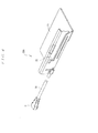
FIG. 4 is a rear oblique perspective view from above of the antenna device used for the display device shown inFIG. 1 ; -
FIG. 5 shows the antenna device shown inFIG. 4 , in whichFIG. 5A is a plan view, andFIG. 5B is a front view; -
FIG. 6 shows the antenna device shown inFIG. 4 , in whichFIG. 6A is a right side view,FIG. 6B is a left side view, andFIG. 6C is a back view; -
FIG. 7 is a plan view schematically showing the trial display device, in which a pair of antennas is arranged on both sides of an upper surface of the flat-panel display portion; -
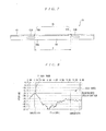
FIG. 8 is a graph showing measurement results of transmission performance of a high frequency signal obtained by a network analyzer between the antennas adjacent to each other in the trial display device shown inFIG. 7 ; -
FIG. 9 is an explanatory diagram schematically showing a positional relation between a pair of antennas arranged on both sides of the upper surface of the flat-panel display portion and a wireless LAN module provided inside the display device; -
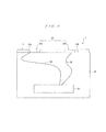
FIG. 10 shows situations in which radio waves radiated from each of a pair of the antennas arranged on the both sides of an upper surface of the flat-panel display portion pass through an aperture formed in the metal plate, in whichFIG. 10A is a plan view schematically showing a situation in which radio waves radiated from the antenna pass through an aperture formed in the metal plate in a case where each antenna is arranged at a center in a depth direction of the flat-panel display portion spaced from the aperture formed in the metal plate, andFIG. 10B is a plan view schematically showing a situation in which radio waves radiated from each antenna pass through an aperture formed in the metal plate in a case where each antenna is arranged on a first or rear edge, of the flat-panel display portion and the metal plate with the apertures is arranged on an opposite second or front edge thereof; and -
FIG. 11 is a perspective view of a conventional antenna device. - A display device 1 shown in
FIG. 1 to FIG. 3 is applied to a flat TV set and is useable with a Multiple Input and Multiple Output (MIMO)system which complies with wireless LAN standard "IEEE 802. 11n". The display device 1 comprises a flat-panel display portion 10 and anantenna device 20 for a wireless LAN. - The flat-
panel display portion 10 is formed in a substantially rectangular shape, having thickness t in a depth direction (upper and lower direction inFIG. 1 ), with anupper surface 10a, alower surface 10b, and left andright sides FIG. 1 )in the depth direction of theupper surface 10a of the flat-panel display portion 10, a linearly extendingmetal plate 11 is provided along the front end edge. Themetal plate 11, has portions which protrude upwardly from theupper surface 10a of the flat-panel display portion 10 and is made from a flat rectangular panel. Themetal panel 11 includes plural (two in the instant embodiment)apertures antenna - The
antenna device 20 comprises multiple (two in the instant embodiment)antennas FIG. 1 , themultiple antennas metal plate 11. Themultiple antennas adjacent antennas - The predetermined distance D is a distance between the adjacent antennas, where a ratio (voltage standing wave ratio: VSWR) of a predetermined voltage at an output side to a predetermined voltage at an input side, is below -20 dB, when a high frequency signal having a predetermined voltage is input from one antenna and the predetermined Voltage is derived thereby from the other antenna. To verify the predetermined distance D, a transmission performance of the high frequency signal between the adjoined antennas is measured in a trial display device shown in
FIG. 7 using the network analyzer. - The
trial display device 51 shown inFIG. 7 includes anantenna device 70 for a wireless LAN on anupper surface 60a of a flat-panel display portion 60. At the front end edge (upper end edge inFIG. 7 ) in the depth direction of theupper surface 60a of the flat-panel display portion 60, a linearly extendingmetal plate 61 is provided along the front end edge. Theantenna device 70 comprises a pair ofantennas metal plate 61. Spacing between the pair of theantennas antenna metal plate 61, anaperture antennas upper surface 60a of the flat-panel display portion 60 spaced from themetal plate 61. - In the
trial display device 51 shown inFIG.7 , a network analyzer (not shown) is utilized to input a high frequency signal (ranging from about 2.00 GHz to 6.00 GHz) having a predetermined voltage from one of the pair of theantennas FIG. 8 . - As shown in
FIG. 8 , where the predetermined distance D between the pair of theantennas antennas antennas - A description will now be provided of the
antenna 20A only, as themultiple antennas antenna 20A is a so-called inverted F antenna, and comprises, as shown inFIG. 4 to FIG. 6 , a rectangular and tab-like ground plate 21 and a tab-like radiation element 22 rising or extending up from one side edge of theground plate 21. Theantenna 20A is made by stamping and forming a metal plate. As best shown inFIG. 5B , acore wire 30a of acoaxial cable 30 is soldered to theradiation elements 22, and abraid 30b is soldered to theground plate 21. As shown inFig. 9 , thecoaxial cable 30 is connected to awireless LAN module 40 to control MIMO communication. - As shown in
FIG. 1 , themultiple antennas upper surface 10a of the flat-panel display portion 10 so that theradiation elements 22 face theapertures metal plate 11, and are arranged on the same straight line with themetal plate 11. That is, themultiple antennas radiation element 22 is positioned inside one of theapertures metal plate 11, and is positioned along the front end edge, in the depth direction, of theupper surface 10a of the flat-panel display portion 10. - In the instant embodiment, the width L of each
aperture antenna antenna FIG. 1 , where theradiation elements 22 of eachantenna metal plate 11, the width L of eachaperture antenna panel display portion 10 and theantenna device 20 for the wireless LAN. - With the display device 1, having such a configuration, when sending the MIMO, a high frequency radio wave having either 2.4 GHz band or 5 GHz band is radiated from the both
antennas radiation elements 22 of bothantennas FIG. 1 ) of the display device, at a radiation angle of α (seeFIG. 10A and FIG. 10B ). Further, when receiving the MIMO, the high frequency radio wave having either 2.4 GHz band or 5 GHz band radiated from the access point is received by the bothantennas - The arrangement of the
antenna device 20 for the wireless LAN on the upper surface 10A of the flat-panel display portion 10 allows radiation of radio waves far away, without being affected by the metal body placed around the display device 1. Conversely, where theantenna device 20 for the wireless LAN is arranged on thelower surface 10b of the flat-panel display portion 10, when the metal body is used in a pedestal (not shown) on which the flat-panel display portion 10 is mounted, the antenna device is susceptible to influence by the metal body. Moreover, if theantenna device 20 for the wireless LAN is arranged on one or bothsides panel display portion 10, when the display device 1 is disposed in the vicinity of a wall on which the metal body is provided, the antenna device is susceptible to influence by the metal body. However, when theantenna device 20 for the wireless LAN is arranged on theupper surface 10a of the flat-panel display portion 10, such drawbacks will not occur. - The
antenna device 20 comprises themultiple antennas upper surface 10a of the flat-panel display portion 10. At a position of themetal plate 11 corresponding to eachantenna aperture multiple antennas aperture metal plate 11 provided in the flat-panel display portion 10. This radiates radio waves to a remote location without being affected by themetal plate 11 provided on the flat-panel display portion 10. Further, the provision of themetal plate 11 on theupper surface 10a of the flat-panel display portion 10 mechanically strengthens the flat-panel display portion 10. - Furthermore, as shown in
FIG. 1 , themultiple antennas upper surface 10a of the flat-panel display portion 10 so that theradiation elements 22 face theapertures metal plate 11. For this reason, radio waves are smoothly radiated towards an access point through theapertures - Moreover, as shown in
FIG. 1 , themultiple antennas upper surface 10a of the flat-panel display portion 10 such that theradiation elements 22 are arranged on the same straight line with themetal plate 11. In other words, themultiple antennas radiation element 22 thereof is positioned inside theapertures metal plate 11, as well as along the front edge in the depth direction of theupper surface 10a of the flat-panel display portion 10. For this reason, when radio waves are radiated from theradiation elements antennas apertures metal plate 11, regardless of the size of a radiation angle α of the radio waves, thus significantly mitigating influence by themetal plate 11. - Since the
multiple antennas adjacent antennas antenna antenna FIG. 9 , the twoantennas wireless LAN module 40 installed inside the display device 1 bycoaxial cables 30. In this way, the connection of the twoantennas wireless LAN module 40 through thecoaxial cables 30 keeps theantennas wireless LAN module 40, thus mitigating significantly influence by noises induced from thewireless LAN module 40. - While the embodiment of the present invention is described, it is not limited thereto. The present invention may allow for various modifications and improvements. For example, the field to which the display device 1 is to be applied may be those with display devices such as a Personal Computer (PC) and a note book PC. Furthermore, the
multiple antennas radiation elements 22 are arranged on the same straight line with themetal plate 11. They may be arranged so as to be off the straight line on which themetal plate 11 is standing. For instance, as shown inFIG. 10A , themultiple antennas panel display portion 10 and spaced away from the theapertures metal plate 11. Alternatively, as shown inFIG. 10B , they may be arranged on the rear end edge, in the depth direction, of the flat-panel display portion further away from theapertures metal plate 11. - In either case, as shown in
FIG. 10A or FIG. 10B , it is preferable to set the width of theapertures antenna metal plate 11. Further, whereas in the instant embodiments, theantenna device 20 is composed of the twoantennas antenna device 20 is not limited thereto. Theantenna device 20 may be composed of three or more antennas. Furthermore, an aperture is formed in themetal plate 11 at each position corresponding to an antenna. In the case where theantenna device 20 is composed of three or more antennas, three or more corresponding apertures may be formed corresponding to the number of the antennas. Moreover, eachantenna - Key to main reference numerals in drawings:
- 1: display device
- 10: flat-panel display portion
- 10a: upper surface
- 11: metal plate
- 12A,12B: aperture
- 20: antenna device
- 20A,20B: antenna
- 21: ground plate
- 22: radiation element
Claims (3)
- A display device (1) comprising:a flat-panel display portion(10)on an upper surface (10a)of which a linearly extending metal plate(11)is provided; andan antenna device (20) for a wireless LAN arranged on the upper surface (10a) of the flat-panel display portion (10),wherein the antenna device (20) comprises multiple antennas (20A, 20B) arranged side-by-side on a straight line and arranged parallel to the metal plate (11), the multiple antennas (20A, 20B) being arranged so that a predetermined distance (D) between adjacent said antennas (20A, 20B) becomes the shortest, and
wherein plural apertures (12A, 12B) are formed at a position corresponding to each antenna (20A, 20B) of the metal plate (11). - The display device (1) according to claim 1, wherein each of the multiple antennas (20A, 20B) comprises a tab-like ground plate (21) and a tab-like radiation element (22) extending from an edge of the ground plate (21) , wherein each of the multiple antennas (20A, 20B) is arranged so that its radiation element (22) faces toward one said aperture (12A, 12B) formed in the metal plate(11).
- The display device (1) according to claim 2, wherein the radiation elements (22) of the multiple antennas(20A, 20B) and the metal plate (11) are arranged on said straight line.
Applications Claiming Priority (1)
| Application Number | Priority Date | Filing Date | Title |
|---|---|---|---|
| JP2010219746A JP2012075031A (en) | 2010-09-29 | 2010-09-29 | Display device |
Publications (1)
| Publication Number | Publication Date |
|---|---|
| EP2437349A1 true EP2437349A1 (en) | 2012-04-04 |
Family
ID=44983432
Family Applications (1)
| Application Number | Title | Priority Date | Filing Date |
|---|---|---|---|
| EP11181185A Withdrawn EP2437349A1 (en) | 2010-09-29 | 2011-09-14 | Display device |
Country Status (5)
| Country | Link |
|---|---|
| US (1) | US20120075152A1 (en) |
| EP (1) | EP2437349A1 (en) |
| JP (1) | JP2012075031A (en) |
| KR (1) | KR20120033234A (en) |
| CN (1) | CN102568316A (en) |
Families Citing this family (3)
| Publication number | Priority date | Publication date | Assignee | Title |
|---|---|---|---|---|
| WO2017120715A1 (en) * | 2016-01-11 | 2017-07-20 | Hewlett-Packard Development Company, L.P. | Display cover for electronic devices |
| EP4239443A4 (en) | 2020-12-04 | 2024-05-01 | Samsung Electronics Co., Ltd. | ELECTRONIC DEVICE COMPRISING A ROLL-UP DISPLAY |
| WO2023175998A1 (en) * | 2022-03-16 | 2023-09-21 | パナソニックIpマネジメント株式会社 | Wireless communication device |
Citations (7)
| Publication number | Priority date | Publication date | Assignee | Title |
|---|---|---|---|---|
| US20040212496A1 (en) * | 2003-04-25 | 2004-10-28 | Villaseca Eduardo H. | Coaxial cable antenna for communication with implanted medical devices |
| US20050073462A1 (en) * | 2003-10-06 | 2005-04-07 | Huei Lin | Multi-band antenna |
| US20050146475A1 (en) * | 2003-12-31 | 2005-07-07 | Bettner Allen W. | Slot antenna configuration |
| EP1921710A2 (en) * | 2006-11-09 | 2008-05-14 | Tyco Electronics AMP K.K. | Antenna |
| US20080316120A1 (en) * | 2007-06-19 | 2008-12-25 | Kabushiki Kaisha Toshiba | Electronic apparatus |
| US20090278282A1 (en) * | 2008-05-09 | 2009-11-12 | Foxconn Technology Co., Ltd. | Insert-molded cover and method for manufacturing same |
| JP2010004318A (en) | 2008-06-20 | 2010-01-07 | Panasonic Corp | Antenna apparatus |
Family Cites Families (11)
| Publication number | Priority date | Publication date | Assignee | Title |
|---|---|---|---|---|
| JP2000172376A (en) * | 1998-12-08 | 2000-06-23 | Toshiba Corp | Information processing device |
| JP2002151928A (en) * | 2000-11-08 | 2002-05-24 | Toshiba Corp | Antennas and electronic devices incorporating antennas |
| JP3830358B2 (en) * | 2001-03-23 | 2006-10-04 | 日立電線株式会社 | Flat antenna and electric device having the same |
| JP4664543B2 (en) * | 2001-07-26 | 2011-04-06 | 株式会社東芝 | Electronic device and mounting method of wireless antenna |
| US6879293B2 (en) * | 2002-02-25 | 2005-04-12 | Tdk Corporation | Antenna device and electric appliance using the same |
| TWI243512B (en) * | 2003-11-18 | 2005-11-11 | Hon Hai Prec Ind Co Ltd | Planar inverted-f antenna and method of manufacturing of the same |
| CN101390254B (en) * | 2006-02-28 | 2013-01-02 | 富士通株式会社 | Antenna device, electronic device and antenna cover |
| JP5132370B2 (en) * | 2007-03-30 | 2013-01-30 | パナソニック株式会社 | MIMO communication equipment |
| JP2009044697A (en) * | 2007-08-13 | 2009-02-26 | Nippon Antenna Co Ltd | Planar antenna |
| JP2010010822A (en) * | 2008-06-24 | 2010-01-14 | Toshiba Corp | Electronic device |
| US8325094B2 (en) * | 2009-06-17 | 2012-12-04 | Apple Inc. | Dielectric window antennas for electronic devices |
-
2010
- 2010-09-29 JP JP2010219746A patent/JP2012075031A/en active Pending
-
2011
- 2011-08-19 KR KR1020110082587A patent/KR20120033234A/en not_active Withdrawn
- 2011-09-14 EP EP11181185A patent/EP2437349A1/en not_active Withdrawn
- 2011-09-28 CN CN2011103096464A patent/CN102568316A/en active Pending
- 2011-09-29 US US13/248,303 patent/US20120075152A1/en not_active Abandoned
Patent Citations (7)
| Publication number | Priority date | Publication date | Assignee | Title |
|---|---|---|---|---|
| US20040212496A1 (en) * | 2003-04-25 | 2004-10-28 | Villaseca Eduardo H. | Coaxial cable antenna for communication with implanted medical devices |
| US20050073462A1 (en) * | 2003-10-06 | 2005-04-07 | Huei Lin | Multi-band antenna |
| US20050146475A1 (en) * | 2003-12-31 | 2005-07-07 | Bettner Allen W. | Slot antenna configuration |
| EP1921710A2 (en) * | 2006-11-09 | 2008-05-14 | Tyco Electronics AMP K.K. | Antenna |
| US20080316120A1 (en) * | 2007-06-19 | 2008-12-25 | Kabushiki Kaisha Toshiba | Electronic apparatus |
| US20090278282A1 (en) * | 2008-05-09 | 2009-11-12 | Foxconn Technology Co., Ltd. | Insert-molded cover and method for manufacturing same |
| JP2010004318A (en) | 2008-06-20 | 2010-01-07 | Panasonic Corp | Antenna apparatus |
Also Published As
| Publication number | Publication date |
|---|---|
| JP2012075031A (en) | 2012-04-12 |
| CN102568316A (en) | 2012-07-11 |
| US20120075152A1 (en) | 2012-03-29 |
| KR20120033234A (en) | 2012-04-06 |
Similar Documents
| Publication | Publication Date | Title |
|---|---|---|
| US12160031B2 (en) | Feed network of base station antenna, base station antenna, and base station | |
| EP3975337B1 (en) | Antenna unit and terminal device | |
| US7289068B2 (en) | Planar antenna with multiple radiators and notched ground pattern | |
| JP6240202B2 (en) | Self-grounding antenna device | |
| EP2068394B1 (en) | Data processing device with beam steering and/or forming antennas | |
| JP6748716B2 (en) | Self-grounding bow-tie antenna device that can be installed on a wall, petal of the same, and manufacturing method thereof | |
| CN103367917B (en) | Mobile device | |
| US10312584B2 (en) | Dual antenna device | |
| WO2021104191A1 (en) | Antenna unit and electronic device | |
| CN111864362A (en) | Antenna modules and electronic equipment | |
| US7498995B2 (en) | UWB antenna having 270 degree coverage and system thereof | |
| US8836605B2 (en) | Embedded antenna | |
| EP2437349A1 (en) | Display device | |
| US20110273352A1 (en) | Antenna Structure | |
| WO2021083223A1 (en) | Antenna unit and electronic device | |
| US20230033219A1 (en) | Electronic device | |
| US20080150806A1 (en) | Multiple input multiple output antenna | |
| WO2021083213A1 (en) | Antenna unit and electronic device | |
| WO2021083212A1 (en) | Antenna unit and electronic device | |
| CN118367337A (en) | Antenna structure and wireless module suitable for 5GHz bandwidth | |
| JP2022102083A (en) | Antenna, antenna device, and communication device | |
| HK1216942B (en) | A self-grounded antenna arrangement |
Legal Events
| Date | Code | Title | Description |
|---|---|---|---|
| PUAI | Public reference made under article 153(3) epc to a published international application that has entered the european phase |
Free format text: ORIGINAL CODE: 0009012 |
|
| AK | Designated contracting states |
Kind code of ref document: A1 Designated state(s): AL AT BE BG CH CY CZ DE DK EE ES FI FR GB GR HR HU IE IS IT LI LT LU LV MC MK MT NL NO PL PT RO RS SE SI SK SM TR |
|
| AX | Request for extension of the european patent |
Extension state: BA ME |
|
| 17P | Request for examination filed |
Effective date: 20120927 |
|
| 17Q | First examination report despatched |
Effective date: 20150420 |
|
| STAA | Information on the status of an ep patent application or granted ep patent |
Free format text: STATUS: THE APPLICATION IS DEEMED TO BE WITHDRAWN |
|
| 18D | Application deemed to be withdrawn |
Effective date: 20151031 |