EP2437269A1 - Method for joint configuration of nuclear power plant fuel - Google Patents
Method for joint configuration of nuclear power plant fuel Download PDFInfo
- Publication number
- EP2437269A1 EP2437269A1 EP10780049A EP10780049A EP2437269A1 EP 2437269 A1 EP2437269 A1 EP 2437269A1 EP 10780049 A EP10780049 A EP 10780049A EP 10780049 A EP10780049 A EP 10780049A EP 2437269 A1 EP2437269 A1 EP 2437269A1
- Authority
- EP
- European Patent Office
- Prior art keywords
- assemblies
- fuel elements
- new
- fuel
- spent fuel
- Prior art date
- Legal status (The legal status is an assumption and is not a legal conclusion. Google has not performed a legal analysis and makes no representation as to the accuracy of the status listed.)
- Granted
Links
Images






Classifications
-
- G—PHYSICS
- G21—NUCLEAR PHYSICS; NUCLEAR ENGINEERING
- G21C—NUCLEAR REACTORS
- G21C19/00—Arrangements for treating, for handling, or for facilitating the handling of, fuel or other materials which are used within the reactor, e.g. within its pressure vessel
- G21C19/20—Arrangements for introducing objects into the pressure vessel; Arrangements for handling objects within the pressure vessel; Arrangements for removing objects from the pressure vessel
- G21C19/205—Interchanging of fuel elements in the core, i.e. fuel shuffling
-
- G—PHYSICS
- G21—NUCLEAR PHYSICS; NUCLEAR ENGINEERING
- G21D—NUCLEAR POWER PLANT
- G21D3/00—Control of nuclear power plant
- G21D3/001—Computer implemented control
- G21D3/002—Core design; core simulations; core optimisation
-
- G—PHYSICS
- G21—NUCLEAR PHYSICS; NUCLEAR ENGINEERING
- G21D—NUCLEAR POWER PLANT
- G21D3/00—Control of nuclear power plant
- G21D3/001—Computer implemented control
- G21D3/004—Fuel shuffle simulation; fuel shuffle optimisation
-
- Y—GENERAL TAGGING OF NEW TECHNOLOGICAL DEVELOPMENTS; GENERAL TAGGING OF CROSS-SECTIONAL TECHNOLOGIES SPANNING OVER SEVERAL SECTIONS OF THE IPC; TECHNICAL SUBJECTS COVERED BY FORMER USPC CROSS-REFERENCE ART COLLECTIONS [XRACs] AND DIGESTS
- Y02—TECHNOLOGIES OR APPLICATIONS FOR MITIGATION OR ADAPTATION AGAINST CLIMATE CHANGE
- Y02E—REDUCTION OF GREENHOUSE GAS [GHG] EMISSIONS, RELATED TO ENERGY GENERATION, TRANSMISSION OR DISTRIBUTION
- Y02E30/00—Energy generation of nuclear origin
- Y02E30/30—Nuclear fission reactors
Definitions
- the invention relates to a method for joint configuration design of fuel elements/assemblies, and more particularly relates to a method for joint configuration design of nuclear power plant fuel elements/assemblies so as to improve the fuel utilization.
- Nuclear power is a new energy which has been paid more and more attention since the first nuclear power plant was built in 1950s. According to statistics, about 441 nuclear power plants have been built in more than 30 countries and regions in the world by the end of 2002, and the generation capacity is about 360 million kilowatts. Now about 40 nuclear power plants are being built and about 60 nuclear power plants are to be built. After completion, the generation capacity will be up to 500 million kilowatts which will take up about 20% of the world's total generating capacity at that time.
- Uranium or plutonium are generally utilized as nuclear fuel in the nuclear reactor, wherein, the fission chain reaction is conducted in a controlled manner and then fission energy is produced continuously from a special atomic boiler for doing work.
- the fuel elements/assemblies loaded in the first reactor core (it is the core of the first cycle for the reactor type refueling when shutdown) generally are all new fuel elements/assemblies.
- There three enrichments for the new fuel assemblies are generally used.
- a method for optimizing the arrangement of the enrichments and quantity of the first reactor core according to the reactivity distribution in the equilibrium cycle is provided in the patent (application No. 200510071705.3 ) of Westinghouse Company, so as to save uranium resources and reach the equilibrium cycle more quickly.
- the first reactor core configuration design is entirely independent and all the fuel assemblies loaded are still new, except that the range of the enrichments is wider, the types of the new fuel assemblies are more and a low-leakage loading patterns is utilized.
- the enrichments of the new fuel assemblies in use are generally much higher than that of nature uranium (for example, the smallest enrichment of the new fuel assemblies used in the first reactor core of Daya Bay Nuclear Power Station is 1.8% that is much higher than that of natural uranium with value of 0.71 %), and there is no suitable alternative in the first core for the spent fuel assemblies that can not be used any longer by the operating units, resulting in small scope of application and less practical value to other reactor types, and just saving the cost of the new fuel assemblies with natural enrichment for the boiling water reactor which has small effect compared with the cost of the first core.
- the first reactor core configuration design is still completely independent, and just the spent fuel assemblies that can not be used by the operating units any longer is loaded, such that there is no interaction and effect on the reactor core configuration design of the units that have been running.
- An objective of this invention is aimed to the disadvantage that, in the prior art, among several units of the same reactor type with interchangeable fuel elements/assemblies, the configuration design of the nuclear fuel elements/assemblies in reactor core is relatively independent and lack of unified coordinate optimization, and the fuel burnup is low, and then to provide a method for joint configuration design of nuclear power plant fuel elements/assemblies.
- a technical solution utilized in this invention to solve its technical problem is providing a method for joint configuration design of nuclear power plant fuel elements/assemblies, comprising steps implemented in fuel elements/assemblies joint configuration design conducted between at least one operating unit and at least one new starting unit with the first core:
- the spent fuel elements/assemblies having burned once and the spent fuel elements/assemblies having burned twice described herein are defined by the roughly reactivity after the fuel elements/assemblies have burned once and twice respectively, rather than by the real loaded times.
- the method for obtaining and using the spent fuel elements/assemblies in reserve having burned once which is mentioned in steps (S1), (S2) and (S3) also comprises the method for obtaining and using the spent fuel elements/assemblies having burned once, the spent fuel elements/assemblies having burned twice and the spent fuel elements/assemblies having burned more times in such reactor core.
- the method for joint configuration design of nuclear power plant fuel elements/assemblies of the present invention between the steps (S2) and (S3) further comprises storage of the spent fuel elements/assemblies in reserve having burned once which are obtained from step (S2) in the spent fuel pool or spent fuel storage container, so as to satisfy the requirements of transportation safely after storage, that is storing the spent fuel elements/assemblies having burned once and the spent fuel elements/assemblies having burned twice in step (S2) (with respect to the reactor type refueling when shutdown), and the spent fuel elements/assemblies having burned partially (with respect to the reactor type refueling when non-shutdown), once the requirements for transportation comprising the criticality safety, radiation shielding, cooling and so on are satisfied, the spent fuel elements/assemblies in reserve to be used are transported from the operating units to the new starting units with the first cores by the transporting container of spent fuel.
- the arrangement of the first reactor core of the at least one new starting unit is based on the refueling mode in which the at least one operating units are added with the new fuel elements/assemblies before or after.
- the spent fuel elements/assemblies having burned once and the new fuel elements/assemblies are arranged alternatively in the reactor core of the at least one operating unit or in the first reactor core of the new starting unit, such that the new fuel elements/assemblies are arranged around the spent fuel elements/assemblies having burned once.
- Such alternative arrangement can improve the burnup of the spent fuel elements/assemblies having burned once in the present cycle, improve the discharge burnup, and improve the fuel efficiency.
- the step (S3) also comprises arranging a scheduled number of spent fuel elements/assemblies having burned twice taken from the at least one operating unit into the first reactor core of the new starting unit.
- step (S1) for at least one operating unit, 1 ⁇ 29 new fuel assemblies are added to the at least one operating unit, based on the equilibrium cycle or transition cycle reactor core configuration design; wherein, with respect to the reactor core with 157 fuel assemblies, 1 ⁇ 29 new fuel assemblies are added to the at least one operating unit, such that number of the new fuel assemblies is up to 101; the reactor core with more fuel assemblies can be added with more new fuel assemblies; with respect to the reactor type refueling when non-shutdown, the addition means loading more new fuel assemblies during a period of time.
- 1, 4, 5, 8, 9, 12, 13, 16, 17, 20, 21, 24, 25, 28 or 29 new fuel assemblies are added to the at least one operating unit.
- the method of adding fuel elements/assemblies is applicable to the reactor core having the central fuel assembly and showing a quarter-symmetry. The added quantity varies correspondingly with respect to the reactor core showing other symmetry or in other refueling modes.
- step (S1) the reactor cores of the at least one operating unit have 157 fuel assemblies;
- the first reactor cores of the at least one new starting unit comprise 80 ⁇ 100 new fuel assemblies, 30 ⁇ 49 spent fuel assemblies having burned once and the rest spent fuel assemblies having burned twice.
- the long-term operating units described herein are the units refueling every 18 months or every 24 months; the short-term operating units described herein are the units refueling quarter or third of the fuel assemblies every year.
- the new fuel assemblies are with relatively high enrichments equal to that of the new fuel assemblies used in the equilibrium cycle.
- the technical solution of the present invention is about a design for nuclear fuel elements/assemblies configuration conducted jointly by several units with interchangeable fuel elements/assemblies.
- the first core of the new starting units may totally use the fuel elements/assemblies with relatively high enrichments which are identical or equivalent to the equilibrium cycle enrichments.
- a part of new fuel elements/assemblies with relatively high enrichments may be put into one or more operating units for combustion, such that the new fuel elements/assemblies loaded in the operating units is much more than when such method is not implemented, and then considerable spent fuel elements/assemblies having burned once are obtained.
- spent fuel elements/assemblies having burned twice may be provided by the operating units additionally (taking the reactor core with 157 fuel assemblies refueling every 18 months for example). From the considerable obtained spent fuel elements/assemblies having burned once and spent fuel elements/assemblies having burned twice, the spent fuel elements/assemblies with the desired quantity and burnup may be selected to construct the first reactor cores of the new starting units together with new fuel elements/assemblies with relatively high enrichments.
- the average discharge burnup of the operating units added with new fuel elements/assemblies and the first reactor cores of the new starting units is higher than that of the equilibrium cycle (generally, the average discharge burnup of the first reactor cores of the new starting unit is less than 50% of that of the equilibrium cycle).
- the reactor core with 157 fuel assemblies of pressurized-water reactor (PWR) nuclear power plant refueling every 18 months is taken as an example for illustration, wherein, the reactor core comprises the new fuel elements/assemblies, the spent fuel elements/assemblies having burned once and the spent fuel elements/assemblies having burned twice.
- the spent fuel elements/assemblies having burned once and the spent fuel elements/assemblies having burned twice described herein are defined by the roughly reactivity after the fuel elements/assemblies have burned once and twice respectively, rather than by the real loaded times.
- the method for obtaining and using the spent fuel elements/assemblies in reserve having burned once which is mentioned in steps (S1), (S2) and (S3) also comprises the method for obtaining and using the spent fuel elements/assemblies having burned once, the spent fuel elements/assemblies having burned twice and the spent fuel elements/assemblies having burned more times in such reactor core.
- refueling mode of the operating units involved in the method for the joint configuration of nuclear power plant fuel elements/assemblies according to the present invention there is no restriction for the refueling mode of the operating units involved in the method for the joint configuration of nuclear power plant fuel elements/assemblies according to the present invention, and a variety of refueling mode may be implemented directly in the first cores of the new starting units.
- the method is suitable for the reactor types both with refueling when shutdown and with refueling when non-shutdown, and also for PWR, BWR, DUR, and HTR.
- FIG. 13 is the schematic diagram of joint configuration of nuclear power plant fuel assemblies with only one new starting unit with the first core.
- the arrows in the figure just indicate the transfer of the spent fuel elements/assemblies having burned once and the spent fuel elements/assemblies having burned twice. While the new fuel elements/assemblies are purchased from suppliers.
- the twelfth cycle of operating unit NO.1, the fourteenth cycle of operating unit NO.1 and the second cycle of new starting unit NO.1 shown in FIG. 13 are all in the known equilibrium cycle refueling every 18 months in which 72 new fuel assemblies loaded.
- the other two cycles that is the thirteenth cycle of operating unit NO.1 and the first cycle of new starting unit NO.1 are both in the mode refueling every 18 months in which 88 new fuel assemblies loaded.
- FIG. 1 shows the equilibrium cycle of the operating units refueling every 18 months.
- 72 new fuel assemblies with an enrichment of 4.45% are added to each cycle.
- the reactor core comprises 72 new fuel assemblies, 69 spent fuel assemblies having burned once and 16 spent fuel assemblies having burned twice.
- the reactor core configuration design is in symmetry of quarter rotation, and what shown in the figure is one quarter of the reactor core. Because of the single fuel assembly at the center of the reactor core, the quantity of the new fuel assemblies is not equal to that of the spent fuel assemblies having burned once.
- 72 spent fuel assemblies having burned once and 69 spent fuel assemblies having burned twice are obtained, as shown in FIG. 15 .
- the first reactor core of the new starting unit is to be constructed according to the loading mode with 88 new fuel assemblies as shown in FIG. 9 in which there are 88 new fuel assemblies, 41 spent fuel assemblies having burned once and 28 spent fuel assemblies having burned twice. So the first reactor core of the new starting unit requires 88 new fuel assemblies, 41 spent fuel assemblies having burned once and 28 spent fuel assemblies having burned twice. As shown in FIG. 17 , 41 spent fuel assemblies having burned once and 28 spent fuel assemblies having burned twice are respectively selected from 50 spent fuel assemblies having burned once and 66 spent fuel assemblies having burned twice obtained for reserve. Together with 88 new fuel assemblies, they are used to construct the first reactor core of the new starting unit. Or as shown in FIG. 2 and FIG.
- the quantity of the new fuel assemblies additionally added and the loading mode of the first reactor cores of the new starting units may be adjusted based on the quantity of the first cores of new starting units and of the flexibility cycles ready to run in the operating units which are involved in the method for joint configuration design of nuclear power plant fuel elements/assemblies.
- 80, 81, 84, 85, 88, 89, 92 or 93 new fuel assemblies may be added, referring to the loading patterns as shown in FIG. 2 ⁇ FIG.12 respectively.
- the in-in-out loading mode mentioned above is the fuel elements/assemblies loading mode in which new fuel elements/assemblies are placed in the central places during the first burning cycle of the fuel elements/assemblies, in the central places during the second burning cycle of the fuel elements/assemblies, and in the peripheral places during the third burning cycle of the fuel elements/assemblies.
- the in-out-in loading mode (able to lower the temperature difference at the outlet of the reactor core) is the fuel elements/assemblies loading mode in which new fuel elements/assemblies are placed in the central places during the first burning cycle of the fuel elements/assemblies, in the peripheral places during the second burning cycle of the fuel elements/assemblies, and in the central places again during the third burning cycle of the fuel elements/assemblies.
- the spent fuel elements/assemblies having burned are different from the new fuel elements/assemblies.
- the spent fuel elements/assemblies themselves have strong radiation and decay heat
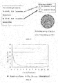
- FIG. 18 shows the decay heat of a single fuel element/assembly as a function of cooling time.
- the decay heat decreases rapidly in the early phase, and slowly in the later phase.
- the decay heat after one-year cooling is less than 6.1kW, while the actual average decay heat after one-year cooling of the spent fuel elements/assemblies is less than 4kW.
- Table 1 Container Technical Requirements Owner Model The Number of Loaded Spent Fuel Assemblies Maximum Heat Load (kW) Maximum Average heat load of the Spent Fuel Assemblies (kW per one) Total Weight (t) GE IF-3000 7 68-70 9.7-10 60.7 BNG.
- NTL-14 5 45 9 85 Lehrer LK-80 12 100 8.3 100 TN TN-12/2(A/B) 12 93/70 7.8/5.8 102/104 NAC NLI-10 10 70 7 97 TN TN-17/2 7 43 6.1 81 PNTL EXCELLOX-3A 5 30 6 72 PNTL EXCELLOX-4 7 40 5.7 92 OCL HZ-75T 7 40 5.7 82 TN TN-13 12 64 5.3 105 GNS CASTOR-S1 6 30 5 79-82
- the average discharge burnup of the operating units and the first reactor cores of the new starting units is 17% higher than that of the 18-month equilibrium cycle in the prior art (generally, the average discharge burnup of the first circle of the new starting unit is less than 50% of that of the equilibrium cycle).
- the first reactor core of every new starting unit in the method for joint configuration design of nuclear power plant fuel elements/assemblies may save about 200,000 pounds of natural uranium, about 32 tons SWU (separative work units) of separative work, about fabrications of 63 fuel assemblies, and about post-processes of 63 spent fuel elements/assemblies, resulting in the total savings of about $ 69.63 million which take up 23.4% of the total fuel costs of the first core.
- the cost savings may vary as the model, the reactor type, the joint configuration of the nuclear power plant fuel elements/assemblies and the price of natural uranium and separation work.
- the joint configuration of the nuclear power plant fuel elements/assemblies can be implemented continuously (as shown in FIG. 14 ).
- the arrows in the figure just indicate the transfer of the spent fuel elements/assemblies having burned once, and the spent fuel elements/assemblies having burned twice are from what accumulated in the long-term running process of the operating units, and the new fuel elements/assemblies are purchased from fuel suppliers.
- the operating units implementing the joint configuration of the nuclear power plant fuel elements/assemblies may utilize 18-month refueling mode, 12-month refueling mode with quarter of fuel assemblies changed, 12-month refueling mode with third of fuel assemblies changed or other refueling modes.
- the first reactor cores of the new starting units may construct their first reactor cores directly based on the requirements of the needed refueling mode, so as to attain 18-month refueling mode, 12-month refueling mode with quarter of fuel assemblies changed, 12-month refueling mode with third of fuel assemblies changed or other refueling modes directly.
- the operating units in 18-month refueling mode have the advantage of high available rate but the average discharge burnup of fuel is relatively low.
- the operating units in 12-month refueling mode with quarter of fuel assemblies changed have the advantage of high average discharge burnup of fuel. 12 spent fuel assemblies having burned once which are original arranged in the peripheral place of the operating units in 18-month refueling mode (as shown in FIG. 1 ) are replaced by the spent fuel assemblies having burned twice.
- the excess spent fuel assemblies having burned once for reverse and a part of the spent fuel assemblies that can not be used in the operating units refueling every 18 months but can be used in the operating units refueling every year with quarter of fuel assemblies changed are arranged into the reactor core of the operating units refueling every year with quarter of fuel assemblies changed for continuously combusting, so as to reduce the quantity of the new fuel assemblies required in the operating units refueling every year with quarter of fuel assemblies changed and to improve total fuel efficiency. So when the fuel elements/assemblies joint configuration is conducted by the reactor core of the operating units in long-term refueling mode and that in short-term refueling mode, the disadvantage of lower fuel efficiency of the operating units in long-term refueling mode can be partially compensated.
- the joint configuration design described above also can be applied to the units refueling when non-shutdown.
- HTR high temperature gas cooled reactor
- New fuel elements with relatively high enrichments same or similar to that in the equilibrium cycle are added additionally and gradually into the HTR units, and a large number of spent fuel elements with different burnups are discharged gradually for reverse; and then the spent fuel elements with different burnup having been discharged and in reserve and the new fuel elements with relatively high enrichments are mixed and loaded into the first core of the new starting units.
- the first cores of the new starting units may not use the fuel elements with a relatively low enrichment any longer wherein the discharge burnup is higher than that in the equilibrium cycle, so as to improve fuel efficiency significantly and save fuel costs.
- a number of spent fuel elements/assemblies may be obtained from other operating units by the method for joint configuration design of nuclear power plant fuel elements/assemblies, as a result, the method for joint configuration design of nuclear power plant fuel elements/assemblies can also improve the ability of units to resist risk of fuel damage.
Landscapes
- Physics & Mathematics (AREA)
- Engineering & Computer Science (AREA)
- Plasma & Fusion (AREA)
- General Engineering & Computer Science (AREA)
- High Energy & Nuclear Physics (AREA)
- Monitoring And Testing Of Nuclear Reactors (AREA)
Abstract
Description
- The invention relates to a method for joint configuration design of fuel elements/assemblies, and more particularly relates to a method for joint configuration design of nuclear power plant fuel elements/assemblies so as to improve the fuel utilization.
- Nuclear power is a new energy which has been paid more and more attention since the first nuclear power plant was built in 1950s. According to statistics, about 441 nuclear power plants have been built in more than 30 countries and regions in the world by the end of 2002, and the generation capacity is about 360 million kilowatts. Now about 40 nuclear power plants are being built and about 60 nuclear power plants are to be built. After completion, the generation capacity will be up to 500 million kilowatts which will take up about 20% of the world's total generating capacity at that time. Uranium or plutonium are generally utilized as nuclear fuel in the nuclear reactor, wherein, the fission chain reaction is conducted in a controlled manner and then fission energy is produced continuously from a special atomic boiler for doing work.
- Now a research for joint configuration of nuclear fuel elements/assemblies among the different reactor types of the nuclear power plant is being conducted. As the shape of fuel elements/assemblies varies as the reactor type, during the joint configuration of nuclear fuel elements/assemblies among different reactor types, the fuel elements/assemblies will experience disintegration and recombinant. While among several units of the same reactor type with interchangeable fuel elements/assemblies, the configuration design of the nuclear fuel elements/assemblies in reactor core is relatively independent and lack of unified coordinate optimization.
- Under the condition where the configuration design of the nuclear fuel elements/assemblies in reactor core is relatively independent, the fuel elements/assemblies loaded in the first reactor core (it is the core of the first cycle for the reactor type refueling when shutdown) generally are all new fuel elements/assemblies. There three enrichments for the new fuel assemblies are generally used. To take the first reactor core of Daya Bay Nuclear Power Station for example, three enrichments by mass of uranium 235 for the new fuel assemblies are 1.8%, 2.4% and 3.1 % respectively.
- A method for optimizing the arrangement of the enrichments and quantity of the first reactor core according to the reactivity distribution in the equilibrium cycle is provided in the patent (application No.
200510071705.3 - In the method provided in the patent (
JP 61-66988 - An objective of this invention is aimed to the disadvantage that, in the prior art, among several units of the same reactor type with interchangeable fuel elements/assemblies, the configuration design of the nuclear fuel elements/assemblies in reactor core is relatively independent and lack of unified coordinate optimization, and the fuel burnup is low, and then to provide a method for joint configuration design of nuclear power plant fuel elements/assemblies.
- A technical solution utilized in this invention to solve its technical problem is providing a method for joint configuration design of nuclear power plant fuel elements/assemblies, comprising steps implemented in fuel elements/assemblies joint configuration design conducted between at least one operating unit and at least one new starting unit with the first core:
- (S1) for at least one operating unit, based on an equilibrium cycle or transition cycle reactor core configuration design, adding at least one new fuel element/assembly to the at least one operating unit, wherein, for a reactor type refueling when non-shutdown, adding at least one new fuel element/assembly means adding more new fuel elements/assemblies in a period of time;
- (S2) after running a fuel cycle, and on the basis of the added new fuel elements/assemblies loaded in step (S1), obtaining more spent fuel elements/assemblies having burned once from the at least one operating unit than that obtained in the reactor core configuration design of the equilibrium cycle or original transition cycle, and keeping said spent fuel elements/assemblies in reserve; wherein, with respect to the reactor type refueling when shutdown, after running one fuel cycle, based on the added new fuel elements/assemblies loaded in step (S1), more spent fuel elements/assemblies having burned once are obtained from the at least one operating unit than that are obtained in the reactor core configuration design of the equilibrium cycle or original transition cycle for reserve; with respect to the reactor type refueling when non-shutdown, after the at least one operating unit has been running for a period of time, based on the added new fuel elements/assemblies loaded in step (S1), more spent fuel elements/assemblies having burned partially are obtained than that are obtained in the reactor core configuration design of the equilibrium cycle or original transition cycle for reserve.
- (S3) for at least one new starting unit with the first core, arranging a scheduled number of new fuel elements/assemblies and the spent fuel elements/assemblies in reserve having burned once which are obtained from step (S2) in the first reactor cores of at least one new starting unit, wherein, for at least one new starting unit with the first core, with respect to the reactor type refueling when shutdown, the scheduled number of new fuel elements/assemblies and the spent fuel elements/assemblies in reserve having burned once which are obtained from step (S2) are arranged in the first reactor cores of at least one new starting unit; with respect to the reactor type refueling when non-shutdown, the scheduled number of new fuel elements/assemblies and the spent fuel elements/assemblies in reserve having burned partially which are obtained from step (S2) are arranged in the first reactor cores of at least one new starting unit.
- The spent fuel elements/assemblies having burned once and the spent fuel elements/assemblies having burned twice described herein are defined by the roughly reactivity after the fuel elements/assemblies have burned once and twice respectively, rather than by the real loaded times. For the reactor core comprising the new fuel elements/assemblies, the spent fuel elements/assemblies having burned once, the spent fuel elements/assemblies having burned twice and the spent fuel elements/assemblies having burned more times, the method for obtaining and using the spent fuel elements/assemblies in reserve having burned once which is mentioned in steps (S1), (S2) and (S3) also comprises the method for obtaining and using the spent fuel elements/assemblies having burned once, the spent fuel elements/assemblies having burned twice and the spent fuel elements/assemblies having burned more times in such reactor core.
- The method for joint configuration design of nuclear power plant fuel elements/assemblies of the present invention, between the steps (S2) and (S3) further comprises storage of the spent fuel elements/assemblies in reserve having burned once which are obtained from step (S2) in the spent fuel pool or spent fuel storage container, so as to satisfy the requirements of transportation safely after storage, that is storing the spent fuel elements/assemblies having burned once and the spent fuel elements/assemblies having burned twice in step (S2) (with respect to the reactor type refueling when shutdown), and the spent fuel elements/assemblies having burned partially (with respect to the reactor type refueling when non-shutdown), once the requirements for transportation comprising the criticality safety, radiation shielding, cooling and so on are satisfied, the spent fuel elements/assemblies in reserve to be used are transported from the operating units to the new starting units with the first cores by the transporting container of spent fuel.
- In the method for joint configuration design of nuclear power plant fuel elements/assemblies of the present invention, the arrangement of the first reactor core of the at least one new starting unit is based on the refueling mode in which the at least one operating units are added with the new fuel elements/assemblies before or after.
- In the method for joint configuration design of nuclear power plant fuel elements/assemblies of the present invention, the spent fuel elements/assemblies having burned once and the new fuel elements/assemblies are arranged alternatively in the reactor core of the at least one operating unit or in the first reactor core of the new starting unit, such that the new fuel elements/assemblies are arranged around the spent fuel elements/assemblies having burned once. Such alternative arrangement can improve the burnup of the spent fuel elements/assemblies having burned once in the present cycle, improve the discharge burnup, and improve the fuel efficiency.
- In the method for joint configuration design of nuclear power plant fuel elements/assemblies of the present invention, the step (S3) also comprises arranging a scheduled number of spent fuel elements/assemblies having burned twice taken from the at least one operating unit into the first reactor core of the new starting unit.
- In the method for joint configuration design of nuclear power plant fuel elements/assemblies of the present invention, in step (S1), for at least one operating unit, 1∼29 new fuel assemblies are added to the at least one operating unit, based on the equilibrium cycle or transition cycle reactor core configuration design; wherein, with respect to the reactor core with 157 fuel assemblies, 1∼29 new fuel assemblies are added to the at least one operating unit, such that number of the new fuel assemblies is up to 101; the reactor core with more fuel assemblies can be added with more new fuel assemblies; with respect to the reactor type refueling when non-shutdown, the addition means loading more new fuel assemblies during a period of time.
- In the method for joint configuration design of nuclear power plant fuel elements/assemblies of the present invention, 1, 4, 5, 8, 9, 12, 13, 16, 17, 20, 21, 24, 25, 28 or 29 new fuel assemblies are added to the at least one operating unit. The method of adding fuel elements/assemblies is applicable to the reactor core having the central fuel assembly and showing a quarter-symmetry. The added quantity varies correspondingly with respect to the reactor core showing other symmetry or in other refueling modes.
- In the method for joint configuration design of nuclear power plant fuel elements/assemblies of the present invention, in step (S1), the reactor cores of the at least one operating unit have 157 fuel assemblies;
- In step (S3), the first reactor cores of the at least one new starting unit comprise 80∼100 new fuel assemblies, 30∼49 spent fuel assemblies having burned once and the rest spent fuel assemblies having burned twice.
- In the method for joint configuration design of nuclear power plant fuel elements/assemblies of the present invention, there are several operating units which comprise long-term refueling and short-term refueling units; and there are steps implemented in the joint configuration of fuel assemblies conducted among the operating units:
- (B1) based on the reactor cores configuration design of the long-term equilibrium cycle or transition cycle, the spent fuel assemblies having burned once which are arranged in the peripheral places of the loading pattern are replaced by the spent fuel assemblies having burned twice, so as to obtain excess spent fuel assemblies having burned once for reserve;
- (B2) the excess spent fuel assemblies having burned once for reserve and the spent fuel assemblies in the long-term operating units are arranged in the short-term operating units.
- In the method for joint configuration design of nuclear power plant fuel elements/assemblies of the present invention, the long-term operating units described herein are the units refueling every 18 months or every 24 months; the short-term operating units described herein are the units refueling quarter or third of the fuel assemblies every year.
- In the method for joint configuration design of nuclear power plant fuel elements/assemblies of the present invention, the new fuel assemblies are with relatively high enrichments equal to that of the new fuel assemblies used in the equilibrium cycle.
- By implementing the method for joint configuration design of nuclear power plant fuel elements/assemblies of the present invention, there are following advantageous effects: several operating units with interchangeable fuel elements/assemblies are joined for nuclear fuel elements/assemblies configuration, such that the operating units and the new starting units with the first cores, and the operating units in different refueling modes can interact, coordinate optimization, and complement each other respectively; all the new fuel elements/assemblies are with relatively high enrichments same or equivalent to that of the new fuel elements/assemblies used in the equilibrium cycle; in the first reactor core of the new starting units, a part of spent fuel elements/assemblies have burned a certain number of cycles, such as one, two or more cycles, while burned for a period time with respect to the reactor type refueling when non-shutdown, so as to satisfy the reactivity requirements for constructing the first reactor cores of the new starting units, resulting in that a variety of desired refueling modes can be implemented in the first reactor cores for the reactor type refueling when shutdown; furthermore, the ability of units to resist risks (a number of fuel elements/assemblies are damaged) can be improved, the method is suitable for both the reactor type refueling when shutdown and non-shutdown, and for (pressurized-water reactor) (PWR), boiling water reactor (BWR), heavy water reactor (HWR), and high temperature reactor (HTR).
-
-
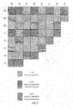
FIG. 1 is a loading pattern of the equilibrium cycle reactor core with 72 new fuel assemblies in the prior art; -
FIG. 2 is the first loading pattern of the first reactor core with 80 new fuel assemblies for the new starting units in the method for the joint configuration of nuclear power plant fuel elements/assemblies according to the present invention; -
FIG. 3 is the second loading pattern of the first reactor core with 80 new fuel assemblies for the new starting units in the method for the joint configuration of nuclear power plant fuel elements/assemblies according to the present invention; -
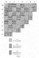
FIG. 4 is the first loading pattern of the first reactor core with 81 new fuel assemblies for the new starting units in the method for the joint configuration of nuclear power plant fuel elements/assemblies according to the present invention; -
FIG. 5 is the second loading pattern of the first reactor core with 81 new fuel assemblies for the new starting units in the method for the joint configuration of nuclear power plant fuel elements/assemblies according to the present invention; -
FIG. 6 is the first loading pattern of the first reactor core with 84 new fuel assemblies for the new starting units in the method for the joint configuration of nuclear power plant fuel elements/assemblies according to the present invention; -
FIG. 7 is the second loading pattern of the first reactor core with 84 new fuel assemblies for the new starting units in the method for the joint configuration of nuclear power plant fuel elements/assemblies according to the present invention; -
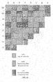
FIG. 8 is a loading pattern of the first reactor core with 85 new fuel assemblies for the new starting units in the method for the joint configuration of nuclear power plant fuel elements/assemblies according to the present invention; -
FIG. 9 is a loading pattern of the first reactor core with 88 new fuel assemblies for the new starting units in the method for the joint configuration of nuclear power plant fuel elements/assemblies according to the present invention; -
FIG. 10 is a loading pattern of the first reactor core with 89 new fuel assemblies for the new starting units in the method for the joint configuration of nuclear power plant fuel elements/assemblies according to the present invention; -
FIG. 11 is a loading pattern of the first reactor core with 92 new fuel assemblies for the new starting units in the method for the joint configuration of nuclear power plant fuel elements/assemblies according to the present invention; -
FIG. 12 is a loading pattern of the first reactor core with 93 new fuel assemblies for the new starting units in the method for the joint configuration of nuclear power plant fuel elements/assemblies according to the present invention; -
FIG. 13 is a schematic view of the joint configuration with only one new starting unit in the method for the joint configuration of nuclear power plant fuel elements/assemblies according to the present invention; -
FIG. 14 is a schematic view of the joint configuration with new starting units added continuously in the method for the joint configuration of nuclear power plant fuel elements/assemblies according to the present invention; -
FIG. 15 is a schematic view when the arrangement with 72 new fuel assemblies in the operating units is changed to that with 88 new fuel assemblies in the method for the joint configuration of nuclear power plant fuel elements/assemblies according to the present invention; -
FIG. 16 is a schematic view when the arrangement with 88 new fuel assemblies in the operating units is changed to that with 72 new fuel assemblies in the method for the joint configuration of nuclear power plant fuel elements/assemblies according to the present invention; -
FIG. 17 is a schematic view when the new fuel assemblies, the spent fuel assemblies in reserve having burned once and the spent fuel assemblies having burned twice are loaded to construct the first cores of the new starting units in the method for the joint configuration of nuclear power plant fuel elements/assemblies according to the present invention; -
FIG. 18 shows the change curve of the decay heat of the spent fuel elements/assemblies vs. time. - The technical solution of the present invention is about a design for nuclear fuel elements/assemblies configuration conducted jointly by several units with interchangeable fuel elements/assemblies. The first core of the new starting units may totally use the fuel elements/assemblies with relatively high enrichments which are identical or equivalent to the equilibrium cycle enrichments. Wherein, a part of new fuel elements/assemblies with relatively high enrichments may be put into one or more operating units for combustion, such that the new fuel elements/assemblies loaded in the operating units is much more than when such method is not implemented, and then considerable spent fuel elements/assemblies having burned once are obtained. Meanwhile, considerable spent fuel elements/assemblies having burned twice may be provided by the operating units additionally (taking the reactor core with 157 fuel assemblies refueling every 18 months for example). From the considerable obtained spent fuel elements/assemblies having burned once and spent fuel elements/assemblies having burned twice, the spent fuel elements/assemblies with the desired quantity and burnup may be selected to construct the first reactor cores of the new starting units together with new fuel elements/assemblies with relatively high enrichments. After the method for joint configuration design of nuclear fuel elements/assemblies has been implemented, the average discharge burnup of the operating units added with new fuel elements/assemblies and the first reactor cores of the new starting units (if the arrangement mode is utilized in which the operating units have been added with new fuel elements/assemblies) is higher than that of the equilibrium cycle (generally, the average discharge burnup of the first reactor cores of the new starting unit is less than 50% of that of the equilibrium cycle).
- Specific steps are as follows:
- (S1) for at least one operating unit, based on the reactor core configuration design of the equilibrium cycle or transition cycle, at least one new fuel element/assembly is added to at least one operating unit, such as 1∼29 new fuel assemblies;
- (S2) after running a fuel cycle, and on basis of the new fuel elements/assemblies added in step (S1), more spent fuel elements/assemblies having burned once which are obtained from the at least one operating unit than that are obtained in the reactor core configuration design of the equilibrium cycle or transition cycle, and said spent fuel elements/assemblies are kept in reserve;
the spent fuel elements/assemblies in reserve having burned once which are obtained from step (S2) are stored in the spent fuel pool; once the requirements for transporting comprising the criticality safety, radiation shielding, cooling and so on are satisfied, the spent fuel elements/assemblies in reserve to be used may be transported from the operating units to new starting units with the first cores by the transporting containers of spent fuel. - (S3) for at least one new starting unit with the first core, a scheduled number of new fuel elements/assemblies, the spent fuel elements/assemblies in reserve having burned once which are obtained from step (S2), and a scheduled number of the spent fuel elements/assemblies having burned twice are arranged in the first reactor cores of at least one new starting unit.
- In the reactor core configuration design of the present invention, the reactor core with 157 fuel assemblies of pressurized-water reactor (PWR) nuclear power plant refueling every 18 months is taken as an example for illustration, wherein, the reactor core comprises the new fuel elements/assemblies, the spent fuel elements/assemblies having burned once and the spent fuel elements/assemblies having burned twice. The spent fuel elements/assemblies having burned once and the spent fuel elements/assemblies having burned twice described herein are defined by the roughly reactivity after the fuel elements/assemblies have burned once and twice respectively, rather than by the real loaded times. For the reactor core comprising the new fuel elements/assemblies, the spent fuel elements/assemblies having burned once, the spent fuel elements/assemblies having burned twice and the spent fuel elements/assemblies having burned more times, the method for obtaining and using the spent fuel elements/assemblies in reserve having burned once which is mentioned in steps (S1), (S2) and (S3) also comprises the method for obtaining and using the spent fuel elements/assemblies having burned once, the spent fuel elements/assemblies having burned twice and the spent fuel elements/assemblies having burned more times in such reactor core.
- There is no restriction for the refueling mode of the operating units involved in the method for the joint configuration of nuclear power plant fuel elements/assemblies according to the present invention, and a variety of refueling mode may be implemented directly in the first cores of the new starting units. The method is suitable for the reactor types both with refueling when shutdown and with refueling when non-shutdown, and also for PWR, BWR, DUR, and HTR.
- To take the PWR nuclear power plant having the reactor with 157 fuel elements/assemblies and refueling when shutdown for example, exemplary embodiments about the fuel elements/assemblies joint configuration of one operating unit and one same type new starting unit with the first core will be illustrated as followed.
-
FIG. 13 is the schematic diagram of joint configuration of nuclear power plant fuel assemblies with only one new starting unit with the first core. The arrows in the figure just indicate the transfer of the spent fuel elements/assemblies having burned once and the spent fuel elements/assemblies having burned twice. While the new fuel elements/assemblies are purchased from suppliers. The twelfth cycle of operating unit NO.1, the fourteenth cycle of operating unit NO.1 and the second cycle of new starting unit NO.1 shown inFIG. 13 are all in the known equilibrium cycle refueling every 18 months in which 72 new fuel assemblies loaded. The other two cycles that is the thirteenth cycle of operating unit NO.1 and the first cycle of new starting unit NO.1 are both in the mode refueling every 18 months in which 88 new fuel assemblies loaded. Specially, as compared to 72 new fuel assemblies with an enrichment of 4.45% needed in the equilibrium cycle, additional 16 new fuel assemblies with an enrichment of 4.45% are added in the thirteenth cycle of operating unit NO.1, such that the new fuel assemblies total up to 88. And the first cycle of new starting unit NO.1 (the first reactor core) can obtain 41 spent fuel assemblies having burned once and 28 spent fuel assemblies having burned twice from the operating unit NO.1. -
FIG. 1 shows the equilibrium cycle of the operating units refueling every 18 months. 72 new fuel assemblies with an enrichment of 4.45% are added to each cycle. The reactor core comprises 72 new fuel assemblies, 69 spent fuel assemblies having burned once and 16 spent fuel assemblies having burned twice. The reactor core configuration design is in symmetry of quarter rotation, and what shown in the figure is one quarter of the reactor core. Because of the single fuel assembly at the center of the reactor core, the quantity of the new fuel assemblies is not equal to that of the spent fuel assemblies having burned once. At the end of the twelfth cycle of operating unit NO.1, 72 spent fuel assemblies having burned once and 69 spent fuel assemblies having burned twice are obtained, as shown inFIG. 15 . - As shown in
FIG. 13 ,16 new fuel assemblies with an enrichment of 4.45% are added to the thirteenth cycle of operating unit NO.1. Such that the number of the new fuel assemblies in the thirteenth cycle of operating unit NO.1 is increased to 88. With the fuel cycle length guaranteed, the number of the needed spent fuel assemblies having burned once as shown inFIG. 9 is reduced to 41, and the number of the spent fuel assemblies having burned twice is increased to 28. As a result, the reactor core now comprises 88 new fuel assemblies, 41 spent fuel assemblies having burned once and 28 spent fuel assemblies having burned twice. As shown inFIG. 15 , after the burned assemblies discharged at the end of the twelfth cycle of operating unit NO. 1 are reloaded to construct the thirteenth cycle of operating unit NO.1, 31 (72-41=31) spent fuel assemblies having burned once and 41 (69-28=41) spent fuel assemblies having burned twice are remained in reserve. - As shown in
FIG. 16 , after the thirteenth cycle of operating unit NO. 1 with the number of the new fuel assemblies increased to 88 has passed one fuel cycle, 88 spent fuel assemblies having burned once and 41 spent fuel assemblies having burned twice can be obtained. The fourteenth cycle of operating unit NO.1 returns into the loading mode of equilibrium circle that is shown inFIG. 1 where there are 72 new fuel assemblies, 69 spent fuel assemblies having burned once and 16 spent fuel assemblies having burned twice, so 69 spent fuel assemblies having burned once and 16 spent fuel assemblies having burned twice are required. As shown inFIG. 16 , after the construction of the fourteenth cycle of operating unit NO. 1 is completed, 19 (88-69=19) spent fuel assemblies having burned once and 25 (41-16=25) spent fuel assemblies having burned twice are remained in reserve. - As shown in
FIG. 17 , by only one flexibility cycle of the thirteenth cycle of operating unit NO.1 in which 16 new fuel assemblies are added, 50 (31+19=50) spent fuel assemblies having burned once and 66 (41+25=66) spent fuel assemblies having burned twice can be obtained for reserve. - The first reactor core of the new starting unit is to be constructed according to the loading mode with 88 new fuel assemblies as shown in
FIG. 9 in which there are 88 new fuel assemblies, 41 spent fuel assemblies having burned once and 28 spent fuel assemblies having burned twice. So the first reactor core of the new starting unit requires 88 new fuel assemblies, 41 spent fuel assemblies having burned once and 28 spent fuel assemblies having burned twice. As shown inFIG. 17 , 41 spent fuel assemblies having burned once and 28 spent fuel assemblies having burned twice are respectively selected from 50 spent fuel assemblies having burned once and 66 spent fuel assemblies having burned twice obtained for reserve. Together with 88 new fuel assemblies, they are used to construct the first reactor core of the new starting unit. Or as shown inFIG. 2 andFIG. 3 , 80 new fuel assemblies, 49 spent fuel assemblies having burned once and 28 spent fuel assemblies having burned twice are loaded to construct the first reactor core of the new starting unit. Or as shown inFIG. 4 andFIG. 5 , 81 new fuel assemblies, 48 spent fuel assemblies having burned once and 28 spent fuel assemblies having burned twice are loaded. Or as shown inFIG. 6 andFIG. 7 , 84 new fuel assemblies, 45 spent fuel assemblies having burned once and 28 spent fuel assemblies having burned twice are loaded. Or as shown inFIG. 8 , 85 new fuel assemblies, 44 spent fuel assemblies having burned once and 28 spent fuel assemblies having burned twice are loaded. Or as shown inFIG. 10 , 89 new fuel assemblies, 44 spent fuel assemblies having burned once and 28 spent fuel assemblies having burned twice are loaded. Or as shown inFIG. 11 , 92 new fuel assemblies, 37 spent fuel assemblies having burned once and 28 spent fuel assemblies having burned twice are loaded. Or as shown inFIG. 12 , 93 new fuel assemblies, 36 spent fuel assemblies having burned once and 28 spent fuel assemblies having burned twice are loaded. As show inFIG. 2 ∼12 , with the increase of new fuel assemblies loaded, the arrangement of the new fuel assemblies and the spent fuel assemblies having burned once at the central region of the reactor core tends to be checkerboard. The checkerboard arrangement as known can improve the burnup of the spent fuel assemblies having burned once in the present cycle, improve discharge burnup and improve fuel efficiency. - In the loading mode of the second cycle of new starting unit NO.1, there are 72 new fuel assemblies refueling every 18 months, which is identical to that in the fourteenth cycle of operating unit NO.1, so the illustration will not be repeated again.
- The quantity of the new fuel assemblies additionally added and the loading mode of the first reactor cores of the new starting units may be adjusted based on the quantity of the first cores of new starting units and of the flexibility cycles ready to run in the operating units which are involved in the method for joint configuration design of nuclear power plant fuel elements/assemblies. For the reactor core described above with 18-month refueling and low leakage, 80, 81, 84, 85, 88, 89, 92 or 93 new fuel assemblies may be added, referring to the loading patterns as shown in
FIG. 2 ∼FIG.12 respectively. As the present inventing is not limited to the low leakage loading mode of in-in-out described above, in-out-in, high leakage (a part of new assemblies being placed in the peripheral place) and other loading mode are also applicable. So more reactor core loading modes may be utilized and more new fuel assemblies with relatively high enrichments may be added to the operating units. The loading patterns described above are just used for illustrating rather than limiting. The in-in-out loading mode mentioned above is the fuel elements/assemblies loading mode in which new fuel elements/assemblies are placed in the central places during the first burning cycle of the fuel elements/assemblies, in the central places during the second burning cycle of the fuel elements/assemblies, and in the peripheral places during the third burning cycle of the fuel elements/assemblies. While the in-out-in loading mode (able to lower the temperature difference at the outlet of the reactor core) is the fuel elements/assemblies loading mode in which new fuel elements/assemblies are placed in the central places during the first burning cycle of the fuel elements/assemblies, in the peripheral places during the second burning cycle of the fuel elements/assemblies, and in the central places again during the third burning cycle of the fuel elements/assemblies. - The spent fuel elements/assemblies having burned are different from the new fuel elements/assemblies. The spent fuel elements/assemblies themselves have strong radiation and decay heat, and
FIG. 18 shows the decay heat of a single fuel element/assembly as a function of cooling time. The decay heat decreases rapidly in the early phase, and slowly in the later phase. In the limiting case with an enrichment of 4.45% and a burnup of 55000MWd/tU, the decay heat after one-year cooling is less than 6.1kW, while the actual average decay heat after one-year cooling of the spent fuel elements/assemblies is less than 4kW. If the spent fuel elements/assemblies are to be transported from one unit to another, a transporting container of spent fuel which satisfies the requirements is needed, wherein, the longer cooling time, the lower the requirements. There are a large number of mature commercial large transporting containers of spent fuel which may be used for transporting the spent fuel elements/assemblies having been cooled for only one year. The known transporting container of spent fuel which can transport the spent PWR fuel elements/assemblies with more than 5kW decay heat are shown in the following table 1.Table 1 Container Technical Requirements Owner Model The Number of Loaded Spent Fuel Assemblies Maximum Heat Load (kW) Maximum Average heat load of the Spent Fuel Assemblies (kW per one) Total Weight (t) GE IF-3000 7 68-70 9.7-10 60.7 BNG. NTL-14 5 45 9 85 Lehrer LK-80 12 100 8.3 100 TN TN-12/2(A/B) 12 93/70 7.8/5.8 102/104 NAC NLI-10 10 70 7 97 TN TN-17/2 7 43 6.1 81 PNTL EXCELLOX- 3A 5 30 6 72 PNTL EXCELLOX-4 7 40 5.7 92 OCL HZ- 75T 7 40 5.7 82 TN TN-13 12 64 5.3 105 GNS CASTOR- S1 6 30 5 79-82 - During the loading, unloading and transporting of the spent fuel elements/assemblies, it is necessary to ensure the critical security, cooling, shielding and isolation from the oxygen so as to avoid excessive oxidation of fuel cladding.
- By implementing the joint configuration of nuclear power plant fuel elements/assemblies, the average discharge burnup of the operating units and the first reactor cores of the new starting units is 17% higher than that of the 18-month equilibrium cycle in the prior art (generally, the average discharge burnup of the first circle of the new starting unit is less than 50% of that of the equilibrium cycle). Such that the first reactor core of every new starting unit in the method for joint configuration design of nuclear power plant fuel elements/assemblies may save about 200,000 pounds of natural uranium, about 32 tons SWU (separative work units) of separative work, about fabrications of 63 fuel assemblies, and about post-processes of 63 spent fuel elements/assemblies, resulting in the total savings of about $ 69.63 million which take up 23.4% of the total fuel costs of the first core. The cost savings may vary as the model, the reactor type, the joint configuration of the nuclear power plant fuel elements/assemblies and the price of natural uranium and separation work.
- With the new starting units with the first cores adding continuously, the joint configuration of the nuclear power plant fuel elements/assemblies can be implemented continuously (as shown in
FIG. 14 ). The arrows in the figure just indicate the transfer of the spent fuel elements/assemblies having burned once, and the spent fuel elements/assemblies having burned twice are from what accumulated in the long-term running process of the operating units, and the new fuel elements/assemblies are purchased from fuel suppliers. - For units refueling when shutdown, the operating units implementing the joint configuration of the nuclear power plant fuel elements/assemblies may utilize 18-month refueling mode, 12-month refueling mode with quarter of fuel assemblies changed, 12-month refueling mode with third of fuel assemblies changed or other refueling modes. The first reactor cores of the new starting units may construct their first reactor cores directly based on the requirements of the needed refueling mode, so as to attain 18-month refueling mode, 12-month refueling mode with quarter of fuel assemblies changed, 12-month refueling mode with third of fuel assemblies changed or other refueling modes directly.
- For the fuel elements/assemblies joint configuration among the operating units, when there are several operating units which comprises the long-term and short-term operating units. The steps of the joint configuration of fuel elements/assemblies among the operating units are as follows:
- (B1) based on the equilibrium cycle configuration design, the spent fuel elements/assemblies having burned once which are original arranged in the peripheral place of the long-term operating units are replaced by the spent fuel elements/assemblies having burned twice, so as to obtain excess spent fuel elements/assemblies having burned once for reserve;
- (B2) the excess spent fuel elements/assemblies having burned once for reserve and a part of spent fuel elements/assemblies in the long-term operating units are arranged in the short-term operating units.
- Take the joint configuration design of nuclear fuel elements/assemblies of the operating units in 18-month refueling mode and 12-month refueling mode with quarter of fuel assemblies changed for example, further illustration is as follow.
- The operating units in 18-month refueling mode have the advantage of high available rate but the average discharge burnup of fuel is relatively low. The operating units in 12-month refueling mode with quarter of fuel assemblies changed have the advantage of high average discharge burnup of fuel. 12 spent fuel assemblies having burned once which are original arranged in the peripheral place of the operating units in 18-month refueling mode (as shown in
FIG. 1 ) are replaced by the spent fuel assemblies having burned twice. The excess spent fuel assemblies having burned once for reverse and a part of the spent fuel assemblies that can not be used in the operating units refueling every 18 months but can be used in the operating units refueling every year with quarter of fuel assemblies changed are arranged into the reactor core of the operating units refueling every year with quarter of fuel assemblies changed for continuously combusting, so as to reduce the quantity of the new fuel assemblies required in the operating units refueling every year with quarter of fuel assemblies changed and to improve total fuel efficiency. So when the fuel elements/assemblies joint configuration is conducted by the reactor core of the operating units in long-term refueling mode and that in short-term refueling mode, the disadvantage of lower fuel efficiency of the operating units in long-term refueling mode can be partially compensated. - The joint configuration design described above also can be applied to the units refueling when non-shutdown. Take the Pebble bed high temperature gas cooled reactor (HTR) units for example in the following to further illustrate the application of the present invention on the units refueling when non-shutdown.
- New fuel elements with relatively high enrichments same or similar to that in the equilibrium cycle are added additionally and gradually into the HTR units, and a large number of spent fuel elements with different burnups are discharged gradually for reverse; and then the spent fuel elements with different burnup having been discharged and in reserve and the new fuel elements with relatively high enrichments are mixed and loaded into the first core of the new starting units. The first cores of the new starting units may not use the fuel elements with a relatively low enrichment any longer wherein the discharge burnup is higher than that in the equilibrium cycle, so as to improve fuel efficiency significantly and save fuel costs.
- In the case where a number of fuel elements/assemblies appear damaged in one unit, a number of spent fuel elements/assemblies may be obtained from other operating units by the method for joint configuration design of nuclear power plant fuel elements/assemblies, as a result, the method for joint configuration design of nuclear power plant fuel elements/assemblies can also improve the ability of units to resist risk of fuel damage.
- The present invention is described by several specific embodiments. It should be understood for a person skilled in the art that various change and equivalent alternations can be made without departing from the scope of the present invention. Additionally, for specific circumstances or situation, various modifications can be made without departing from the scope of the present invention. So, the present invention is not limited to the specific embodiments in disclosure, and should comprise all the embodiments fallen into the scope of the appended claims of present invention.
Claims (11)
- A method for joint configuration design of nuclear power plant fuel elements/assemblies, comprising steps implemented in fuel elements/assemblies joint configuration conducted between at least one operating unit and at least one new starting unit with the first core:(S1) for at least one operating unit, based on an equilibrium cycle or transition cycle reactor core configuration design, adding at least one new fuel element/assembly to the at least one operating unit;(S2) after running a fuel cycle, and on the basis of the added new fuel elements/assemblies loaded in step (S1), obtaining more spent fuel elements/assemblies having burned once from the at least one operating unit than that obtained in the reactor core configuration design of the equilibrium cycle or transition cycle, and keeping said spent fuel elements/assemblies in reserve;(S3) for at least one new starting unit with the first core, arranging a scheduled number of new fuel elements/assemblies and the spent fuel elements/assemblies in reserve having burned once which are obtained from step (S2) in the first reactor cores of at least one new starting unit.
- The method for joint configuration design of nuclear power plant fuel elements/assemblies of claim 1, between the steps (S2) and (S3), further comprising storage of the spent fuel elements/assemblies in reserve having burned once which are obtained from step (S2) in the spent fuel pool or spent fuel storage container, so as to satisfy requirements of safe transporting after storage.
- The method for joint configuration design of nuclear power plant fuel elements/assemblies of claim 1, wherein, the arrangement of the first reactor core of the at least one new starting unit is based on the refueling mode in which the at least one operating units are added with the new fuel elements/assemblies before or after.
- The method for joint configuration design of nuclear power plant fuel elements/assemblies of claim 1, wherein, the spent fuel elements/assemblies having burned once and the new fuel elements/assemblies are arranged in alternation order in the reactor core of the at least one operating unit or in the first reactor core of the new starting unit, such that the new fuel elements/assemblies are arranged around the spent fuel elements/assemblies having burned once.
- The method for joint configuration design of nuclear power plant fuel elements/assemblies of any one of claims 1∼4, wherein, the step (S3) also comprises arranging a scheduled number of spent fuel elements/assemblies having burned twice into the first reactor core of the new starting unit.
- The method for joint configuration design of nuclear power plant fuel elements/assemblies of any one of claims 1∼4, wherein, in step (S1), for at least one operating unit, 1∼29 new fuel elements/assemblies are added to the at least one operating unit, based on the reactor core configuration design of equilibrium cycle or transition cycle.
- The method for joint configuration design of nuclear power plant fuel elements/assemblies of any one of claims 1∼4, wherein, 1,4,5,8,9,12,13,16,17, 20, 21, 24, 25, 28 or 29 new fuel assemblies are added to the at least one operating unit.
- The method for joint configuration design of nuclear power plant fuel elements/assemblies of any one of claims 1∼4, wherein, in step (S1), the reactor cores of the at least one operating unit have 157 fuel assemblies;
in step (S3), the first reactor cores of the at least one new starting unit comprise 80∼100 new fuel assemblies, 30∼49 spent fuel assemblies having burned once and spent fuel assemblies having burned twice loaded in the rest places. - The method for joint configuration design of nuclear power plant fuel elements/assemblies of any one of claims 1∼4, wherein, there are several operating units which comprise long-term and short-term operating units; and there are steps implemented in the fuel elements/assemblies joint configuration conducted among the operating units:(B1) based on the reactor cores configuration design of the long-term equilibrium cycle or transition cycle, the spent fuel elements/assemblies having burned once which are arranged in the peripheral places of the long-term operating units are replaced by the spent fuel elements/assemblies having burned twice, so as to obtain excess spent fuel elements/assemblies having burned once for reserve;(B2) the excess spent fuel elements/assemblies having burned once for reserve and the spent fuel elements/assemblies in the long-term operating units are arranged in the short-term operating units.
- The method for joint configuration design of nuclear power plant fuel elements/assemblies of claim 9, wherein, the long-term operating units refuel every 18 months or every 24 months; the short-term operating units refuel every year with quarter or third of fuel elements/assemblies changed.
- The method for joint configuration design of nuclear power plant fuel elements/assemblies of any one of claims 1∼4, wherein, the new fuel elements/assemblies are with relatively high enrichments same or similar to that of the new fuel elements/assemblies used in the equilibrium cycle.
Applications Claiming Priority (2)
| Application Number | Priority Date | Filing Date | Title |
|---|---|---|---|
| CN200910107548A CN101847450B (en) | 2009-05-27 | 2009-05-27 | Associated disposition method of fuel for nuclear power plant |
| PCT/CN2010/073041 WO2010135968A1 (en) | 2009-05-27 | 2010-05-21 | Method for joint configuration of nuclear power plant fuel |
Publications (3)
| Publication Number | Publication Date |
|---|---|
| EP2437269A1 true EP2437269A1 (en) | 2012-04-04 |
| EP2437269A4 EP2437269A4 (en) | 2014-04-02 |
| EP2437269B1 EP2437269B1 (en) | 2015-07-01 |
Family
ID=42772032
Family Applications (1)
| Application Number | Title | Priority Date | Filing Date |
|---|---|---|---|
| EP10780049.2A Active EP2437269B1 (en) | 2009-05-27 | 2010-05-21 | Method for a joint fuel configuration of nuclear power plants |
Country Status (4)
| Country | Link |
|---|---|
| US (1) | US8953733B2 (en) |
| EP (1) | EP2437269B1 (en) |
| CN (1) | CN101847450B (en) |
| WO (1) | WO2010135968A1 (en) |
Families Citing this family (13)
| Publication number | Priority date | Publication date | Assignee | Title |
|---|---|---|---|---|
| CN103106939B (en) * | 2013-01-15 | 2014-07-02 | 西安交通大学 | A method for transmutation of long-lived and high-radioactive nuclides using pressurized water reactors |
| CN103400619B (en) * | 2013-07-03 | 2016-05-04 | 中国核电工程有限公司 | The stowage of reloading in a kind of advanced person's 1/4 reactor core year |
| US10818403B2 (en) * | 2016-03-29 | 2020-10-27 | Nuscale Power, Llc | Inter-module fuel shuffling |
| JP7278984B2 (en) * | 2020-02-25 | 2023-05-22 | 日立Geニュークリア・エナジー株式会社 | Core and fuel assembly loading method for light water reactor |
| CN111695246A (en) * | 2020-05-26 | 2020-09-22 | 国家核安保技术中心 | Nuclear material balance method, device and equipment and computer storage medium |
| CN113658730A (en) * | 2021-07-06 | 2021-11-16 | 广东核电合营有限公司 | Nuclear power plant secondary neutron source component positioning method, device, equipment and storage medium |
| CN114242283B (en) * | 2021-12-22 | 2024-12-31 | 中国核动力研究设计院 | A fuel loading method for a pressurized water reactor core with a 24-month refueling cycle |
| CN114818280B (en) * | 2022-04-07 | 2025-05-09 | 岭澳核电有限公司 | CPR1000 unit refueling method, device and spent fuel assembly based on spent fuel assembly |
| CN115239161A (en) * | 2022-07-28 | 2022-10-25 | 中国核动力研究设计院 | A method for loading initial core fuel assemblies of pressurized water reactor nuclear power plants |
| CN115376712A (en) * | 2022-08-03 | 2022-11-22 | 上海核工程研究设计院有限公司 | Fuel management method and reactor core of long-period balanced cycle of passive nuclear power plant |
| CN115274163B (en) * | 2022-08-05 | 2024-02-13 | 中国核动力研究设计院 | Fuel assembly management method for reactor core of pressurized water reactor nuclear power plant |
| CN120674122B (en) * | 2025-08-22 | 2025-11-04 | 华能核能技术研究院有限公司 | Nuclear fuel management method and device for multi-module pebble-bed high-temperature gas cooled reactor |
| CN121862472A (en) * | 2026-03-18 | 2026-04-14 | 中广核清洁能源科技(上海)有限公司 | Reactor core arrangement method and reactor pressure device |
Family Cites Families (16)
| Publication number | Priority date | Publication date | Assignee | Title |
|---|---|---|---|---|
| US3503849A (en) * | 1966-01-07 | 1970-03-31 | Atomic Power Dev Ass Inc | Method of replacing subassemblies in nuclear reactors |
| US3432389A (en) * | 1966-07-25 | 1969-03-11 | Combustion Eng | Core design for nuclear reactor |
| SE324412B (en) * | 1966-12-16 | 1970-06-01 | Atomenergi Ab | |
| US3904048A (en) * | 1968-12-02 | 1975-09-09 | Asea Ab | Device for refueling a nuclear reactor having a core comprising a plurality of fuel assemblies |
| DE2236780A1 (en) * | 1972-07-26 | 1974-02-07 | Siemens Ag | PROCEDURE FOR BUILDING AND OPERATING AT LEAST TWO NUCLEAR REACTORS |
| US4040902A (en) * | 1975-04-03 | 1977-08-09 | General Atomic Company | Method for axially shuffling fuel elements in a nuclear reactor |
| GB1559436A (en) * | 1977-05-14 | 1980-01-16 | Timofeev A V | Others nuclear reactors |
| US4451427A (en) * | 1978-02-03 | 1984-05-29 | Combustion Engineering, Inc. | In-core fuel management for nuclear reactor |
| JPS6166988A (en) | 1984-09-11 | 1986-04-05 | 株式会社東芝 | Method of charging fuel |
| US5631939A (en) * | 1994-09-09 | 1997-05-20 | Hitachi, Ltd. | Initial core of nuclear power plant |
| JP4021519B2 (en) * | 1996-06-03 | 2007-12-12 | ゼネラル・エレクトリック・カンパニイ | Method for supplying fuel to the reactor core |
| JP2004144757A (en) * | 2003-11-28 | 2004-05-20 | Toshiba Corp | Reactor core |
| CN1760990B (en) * | 2004-10-15 | 2011-11-30 | 西屋电气有限责任公司 | Improved first core fuel assembly configuration and method of implementing same |
| CN1328730C (en) * | 2004-12-03 | 2007-07-25 | 大亚湾核电运营管理有限责任公司 | Reactor core loading method of pressurized water reactor nuclear power station reactor |
| JP2006234396A (en) * | 2005-02-22 | 2006-09-07 | Nuclear Fuel Ind Ltd | Reactor fuel operation method |
| CN101206930B (en) * | 2006-12-22 | 2011-06-15 | 深圳中广核工程设计有限公司 | Method for cycle using multi-stack combined nuclear fuel |
-
2009
- 2009-05-27 CN CN200910107548A patent/CN101847450B/en active Active
-
2010
- 2010-05-21 EP EP10780049.2A patent/EP2437269B1/en active Active
- 2010-05-21 US US13/322,551 patent/US8953733B2/en active Active
- 2010-05-21 WO PCT/CN2010/073041 patent/WO2010135968A1/en not_active Ceased
Also Published As
| Publication number | Publication date |
|---|---|
| EP2437269A4 (en) | 2014-04-02 |
| WO2010135968A1 (en) | 2010-12-02 |
| US20120069948A1 (en) | 2012-03-22 |
| US8953733B2 (en) | 2015-02-10 |
| EP2437269B1 (en) | 2015-07-01 |
| CN101847450A (en) | 2010-09-29 |
| CN101847450B (en) | 2012-10-03 |
Similar Documents
| Publication | Publication Date | Title |
|---|---|---|
| EP2437269B1 (en) | Method for a joint fuel configuration of nuclear power plants | |
| EP0871958B1 (en) | Seed-blanket reactors | |
| Fridman et al. | Pu recycling in a full Th-MOX PWR core. Part I: Steady state analysis | |
| Gabrielli et al. | ASTRID-like fast reactor cores for burning plutonium and minor actinides | |
| WO2008077297A1 (en) | Multi-reactors combine nuclear fuel cycle using method | |
| Ohashi et al. | Modular high temperature reactor (Modular HTR) contributing the global environment protection | |
| Lee et al. | i-SMR Core Design Option Study with Gadolinium Nitride Coating Burnable Absorber | |
| McMahon et al. | Reload light water reactor core designs for an ultralong operating cycle | |
| Gregg et al. | Effect of highly enriched/highly burnt UO2 fuels on fuel cycle costs, radiotoxicity, and nuclear design parameters | |
| Dekusar et al. | Feasibility studies of BN-800 type reactor with (Pu-Th) O2 fuel for effective incineration of minor actinides | |
| JP7278984B2 (en) | Core and fuel assembly loading method for light water reactor | |
| Dwijayanto et al. | Evaluating the Use of Graphite and BeO Moderators for Micro Molten Salt Reactor | |
| Grouiller et al. | Fuel Cycle interfaces with the ASTRID core | |
| McMahon et al. | Modeling and design of a reload PWR core for a 48-month fuel cycle | |
| Semchenkov et al. | Advanced fuel cycles for WWER-1000 reactors | |
| Flocard et al. | Incineration of PWR actinide waste to launch a low waste thorium-based energy production with ADSs | |
| Choi et al. | Design Characteristics of the Energy Multiplier Module (EM2) | |
| Cockey | Actinide transmutation in the advanced liquid metal reactor (ALMR) | |
| Ghrayeb et al. | Burnup performance of Sodium-cooled fast reactor by utilizing Thorium-based fuels | |
| Ponomarev-Stepnoy et al. | Burning of Weapon-Grade Plutonium In VVer and Htgr Reactors | |
| Kosourov et al. | WWER-1000 fuel cycles: current situation and outlook | |
| Kodochigov et al. | Possibility of different fuel cycles usage in GT-MHR | |
| Kim et al. | Neutronic Self-sustainability of a Breed-and-Burn Fast Reactor Using Super-Simple Fuel Recycling | |
| Kumar et al. | Physics Design of Advanced Heavy Water Reactor | |
| Nagano et al. | Basic evaluation on nuclear characteristics of BWR high burnup MOX fuel and core |
Legal Events
| Date | Code | Title | Description |
|---|---|---|---|
| PUAI | Public reference made under article 153(3) epc to a published international application that has entered the european phase |
Free format text: ORIGINAL CODE: 0009012 |
|
| 17P | Request for examination filed |
Effective date: 20111220 |
|
| AK | Designated contracting states |
Kind code of ref document: A1 Designated state(s): AL AT BE BG CH CY CZ DE DK EE ES FI FR GB GR HR HU IE IS IT LI LT LU LV MC MK MT NL NO PL PT RO SE SI SK SM TR |
|
| DAX | Request for extension of the european patent (deleted) | ||
| A4 | Supplementary search report drawn up and despatched |
Effective date: 20140303 |
|
| RIC1 | Information provided on ipc code assigned before grant |
Ipc: G21D 3/00 20060101ALN20140225BHEP Ipc: G21C 19/20 20060101AFI20140225BHEP |
|
| REG | Reference to a national code |
Ref country code: DE Ref legal event code: R079 Ref document number: 602010025608 Country of ref document: DE Free format text: PREVIOUS MAIN CLASS: G21C0003300000 Ipc: G21C0019200000 |
|
| RIC1 | Information provided on ipc code assigned before grant |
Ipc: G21D 3/00 20060101ALN20141202BHEP Ipc: G21C 19/20 20060101AFI20141202BHEP |
|
| RIC1 | Information provided on ipc code assigned before grant |
Ipc: G21C 19/20 20060101AFI20141209BHEP Ipc: G21D 3/00 20060101ALN20141209BHEP |
|
| RIC1 | Information provided on ipc code assigned before grant |
Ipc: G21C 19/20 20060101AFI20141218BHEP Ipc: G21D 3/00 20060101ALN20141218BHEP |
|
| RIN1 | Information on inventor provided before grant (corrected) |
Inventor name: MA, ZIRONG |
|
| GRAP | Despatch of communication of intention to grant a patent |
Free format text: ORIGINAL CODE: EPIDOSNIGR1 |
|
| INTG | Intention to grant announced |
Effective date: 20150327 |
|
| RAP1 | Party data changed (applicant data changed or rights of an application transferred) |
Owner name: CHINA NUCLEAR POWER TECHNOLOGY RESEARCH INSTITUTE Owner name: CHINA NUCLEAR POWER ENGINEERING COMPANY LTD. Owner name: CHINA GUANGDONG NUCLEAR POWER HOLDING CORPORATION |
|
| GRAS | Grant fee paid |
Free format text: ORIGINAL CODE: EPIDOSNIGR3 |
|
| GRAA | (expected) grant |
Free format text: ORIGINAL CODE: 0009210 |
|
| AK | Designated contracting states |
Kind code of ref document: B1 Designated state(s): AL AT BE BG CH CY CZ DE DK EE ES FI FR GB GR HR HU IE IS IT LI LT LU LV MC MK MT NL NO PL PT RO SE SI SK SM TR |
|
| REG | Reference to a national code |
Ref country code: GB Ref legal event code: FG4D |
|
| REG | Reference to a national code |
Ref country code: AT Ref legal event code: REF Ref document number: 734382 Country of ref document: AT Kind code of ref document: T Effective date: 20150715 Ref country code: CH Ref legal event code: EP |
|
| REG | Reference to a national code |
Ref country code: IE Ref legal event code: FG4D |
|
| REG | Reference to a national code |
Ref country code: DE Ref legal event code: R096 Ref document number: 602010025608 Country of ref document: DE |
|
| REG | Reference to a national code |
Ref country code: AT Ref legal event code: MK05 Ref document number: 734382 Country of ref document: AT Kind code of ref document: T Effective date: 20150701 |
|
| REG | Reference to a national code |
Ref country code: NL Ref legal event code: MP Effective date: 20150701 |
|
| REG | Reference to a national code |
Ref country code: LT Ref legal event code: MG4D |
|
| PG25 | Lapsed in a contracting state [announced via postgrant information from national office to epo] |
Ref country code: LV Free format text: LAPSE BECAUSE OF FAILURE TO SUBMIT A TRANSLATION OF THE DESCRIPTION OR TO PAY THE FEE WITHIN THE PRESCRIBED TIME-LIMIT Effective date: 20150701 Ref country code: GR Free format text: LAPSE BECAUSE OF FAILURE TO SUBMIT A TRANSLATION OF THE DESCRIPTION OR TO PAY THE FEE WITHIN THE PRESCRIBED TIME-LIMIT Effective date: 20151002 Ref country code: LT Free format text: LAPSE BECAUSE OF FAILURE TO SUBMIT A TRANSLATION OF THE DESCRIPTION OR TO PAY THE FEE WITHIN THE PRESCRIBED TIME-LIMIT Effective date: 20150701 Ref country code: FI Free format text: LAPSE BECAUSE OF FAILURE TO SUBMIT A TRANSLATION OF THE DESCRIPTION OR TO PAY THE FEE WITHIN THE PRESCRIBED TIME-LIMIT Effective date: 20150701 Ref country code: NO Free format text: LAPSE BECAUSE OF FAILURE TO SUBMIT A TRANSLATION OF THE DESCRIPTION OR TO PAY THE FEE WITHIN THE PRESCRIBED TIME-LIMIT Effective date: 20151001 |
|
| PG25 | Lapsed in a contracting state [announced via postgrant information from national office to epo] |
Ref country code: PT Free format text: LAPSE BECAUSE OF FAILURE TO SUBMIT A TRANSLATION OF THE DESCRIPTION OR TO PAY THE FEE WITHIN THE PRESCRIBED TIME-LIMIT Effective date: 20151102 Ref country code: HR Free format text: LAPSE BECAUSE OF FAILURE TO SUBMIT A TRANSLATION OF THE DESCRIPTION OR TO PAY THE FEE WITHIN THE PRESCRIBED TIME-LIMIT Effective date: 20150701 Ref country code: ES Free format text: LAPSE BECAUSE OF FAILURE TO SUBMIT A TRANSLATION OF THE DESCRIPTION OR TO PAY THE FEE WITHIN THE PRESCRIBED TIME-LIMIT Effective date: 20150701 Ref country code: IS Free format text: LAPSE BECAUSE OF FAILURE TO SUBMIT A TRANSLATION OF THE DESCRIPTION OR TO PAY THE FEE WITHIN THE PRESCRIBED TIME-LIMIT Effective date: 20151101 Ref country code: PL Free format text: LAPSE BECAUSE OF FAILURE TO SUBMIT A TRANSLATION OF THE DESCRIPTION OR TO PAY THE FEE WITHIN THE PRESCRIBED TIME-LIMIT Effective date: 20150701 Ref country code: AT Free format text: LAPSE BECAUSE OF FAILURE TO SUBMIT A TRANSLATION OF THE DESCRIPTION OR TO PAY THE FEE WITHIN THE PRESCRIBED TIME-LIMIT Effective date: 20150701 Ref country code: SE Free format text: LAPSE BECAUSE OF FAILURE TO SUBMIT A TRANSLATION OF THE DESCRIPTION OR TO PAY THE FEE WITHIN THE PRESCRIBED TIME-LIMIT Effective date: 20150701 |
|
| REG | Reference to a national code |
Ref country code: DE Ref legal event code: R097 Ref document number: 602010025608 Country of ref document: DE |
|
| PG25 | Lapsed in a contracting state [announced via postgrant information from national office to epo] |
Ref country code: IT Free format text: LAPSE BECAUSE OF FAILURE TO SUBMIT A TRANSLATION OF THE DESCRIPTION OR TO PAY THE FEE WITHIN THE PRESCRIBED TIME-LIMIT Effective date: 20150701 Ref country code: SK Free format text: LAPSE BECAUSE OF FAILURE TO SUBMIT A TRANSLATION OF THE DESCRIPTION OR TO PAY THE FEE WITHIN THE PRESCRIBED TIME-LIMIT Effective date: 20150701 Ref country code: DK Free format text: LAPSE BECAUSE OF FAILURE TO SUBMIT A TRANSLATION OF THE DESCRIPTION OR TO PAY THE FEE WITHIN THE PRESCRIBED TIME-LIMIT Effective date: 20150701 Ref country code: CZ Free format text: LAPSE BECAUSE OF FAILURE TO SUBMIT A TRANSLATION OF THE DESCRIPTION OR TO PAY THE FEE WITHIN THE PRESCRIBED TIME-LIMIT Effective date: 20150701 Ref country code: EE Free format text: LAPSE BECAUSE OF FAILURE TO SUBMIT A TRANSLATION OF THE DESCRIPTION OR TO PAY THE FEE WITHIN THE PRESCRIBED TIME-LIMIT Effective date: 20150701 |
|
| PLBE | No opposition filed within time limit |
Free format text: ORIGINAL CODE: 0009261 |
|
| STAA | Information on the status of an ep patent application or granted ep patent |
Free format text: STATUS: NO OPPOSITION FILED WITHIN TIME LIMIT |
|
| REG | Reference to a national code |
Ref country code: FR Ref legal event code: PLFP Year of fee payment: 7 |
|
| PG25 | Lapsed in a contracting state [announced via postgrant information from national office to epo] |
Ref country code: RO Free format text: LAPSE BECAUSE OF FAILURE TO SUBMIT A TRANSLATION OF THE DESCRIPTION OR TO PAY THE FEE WITHIN THE PRESCRIBED TIME-LIMIT Effective date: 20150701 |
|
| 26N | No opposition filed |
Effective date: 20160404 |
|
| PG25 | Lapsed in a contracting state [announced via postgrant information from national office to epo] |
Ref country code: BE Free format text: LAPSE BECAUSE OF NON-PAYMENT OF DUE FEES Effective date: 20160531 Ref country code: SI Free format text: LAPSE BECAUSE OF FAILURE TO SUBMIT A TRANSLATION OF THE DESCRIPTION OR TO PAY THE FEE WITHIN THE PRESCRIBED TIME-LIMIT Effective date: 20150701 |
|
| REG | Reference to a national code |
Ref country code: DE Ref legal event code: R119 Ref document number: 602010025608 Country of ref document: DE |
|
| PG25 | Lapsed in a contracting state [announced via postgrant information from national office to epo] |
Ref country code: BE Free format text: LAPSE BECAUSE OF FAILURE TO SUBMIT A TRANSLATION OF THE DESCRIPTION OR TO PAY THE FEE WITHIN THE PRESCRIBED TIME-LIMIT Effective date: 20150701 Ref country code: LU Free format text: LAPSE BECAUSE OF FAILURE TO SUBMIT A TRANSLATION OF THE DESCRIPTION OR TO PAY THE FEE WITHIN THE PRESCRIBED TIME-LIMIT Effective date: 20160521 |
|
| REG | Reference to a national code |
Ref country code: CH Ref legal event code: PL |
|
| PG25 | Lapsed in a contracting state [announced via postgrant information from national office to epo] |
Ref country code: LI Free format text: LAPSE BECAUSE OF NON-PAYMENT OF DUE FEES Effective date: 20160531 Ref country code: CH Free format text: LAPSE BECAUSE OF NON-PAYMENT OF DUE FEES Effective date: 20160531 |
|
| REG | Reference to a national code |
Ref country code: IE Ref legal event code: MM4A |
|
| PG25 | Lapsed in a contracting state [announced via postgrant information from national office to epo] |
Ref country code: DE Free format text: LAPSE BECAUSE OF NON-PAYMENT OF DUE FEES Effective date: 20161201 |
|
| REG | Reference to a national code |
Ref country code: FR Ref legal event code: PLFP Year of fee payment: 8 |
|
| PG25 | Lapsed in a contracting state [announced via postgrant information from national office to epo] |
Ref country code: IE Free format text: LAPSE BECAUSE OF NON-PAYMENT OF DUE FEES Effective date: 20160521 |
|
| PG25 | Lapsed in a contracting state [announced via postgrant information from national office to epo] |
Ref country code: NL Free format text: LAPSE BECAUSE OF FAILURE TO SUBMIT A TRANSLATION OF THE DESCRIPTION OR TO PAY THE FEE WITHIN THE PRESCRIBED TIME-LIMIT Effective date: 20150701 |
|
| REG | Reference to a national code |
Ref country code: FR Ref legal event code: PLFP Year of fee payment: 9 |
|
| PG25 | Lapsed in a contracting state [announced via postgrant information from national office to epo] |
Ref country code: SM Free format text: LAPSE BECAUSE OF FAILURE TO SUBMIT A TRANSLATION OF THE DESCRIPTION OR TO PAY THE FEE WITHIN THE PRESCRIBED TIME-LIMIT Effective date: 20150701 Ref country code: CY Free format text: LAPSE BECAUSE OF FAILURE TO SUBMIT A TRANSLATION OF THE DESCRIPTION OR TO PAY THE FEE WITHIN THE PRESCRIBED TIME-LIMIT Effective date: 20150701 Ref country code: HU Free format text: LAPSE BECAUSE OF FAILURE TO SUBMIT A TRANSLATION OF THE DESCRIPTION OR TO PAY THE FEE WITHIN THE PRESCRIBED TIME-LIMIT; INVALID AB INITIO Effective date: 20100521 |
|
| PG25 | Lapsed in a contracting state [announced via postgrant information from national office to epo] |
Ref country code: MT Free format text: LAPSE BECAUSE OF NON-PAYMENT OF DUE FEES Effective date: 20160531 Ref country code: MK Free format text: LAPSE BECAUSE OF FAILURE TO SUBMIT A TRANSLATION OF THE DESCRIPTION OR TO PAY THE FEE WITHIN THE PRESCRIBED TIME-LIMIT Effective date: 20150701 Ref country code: TR Free format text: LAPSE BECAUSE OF FAILURE TO SUBMIT A TRANSLATION OF THE DESCRIPTION OR TO PAY THE FEE WITHIN THE PRESCRIBED TIME-LIMIT Effective date: 20150701 Ref country code: MC Free format text: LAPSE BECAUSE OF FAILURE TO SUBMIT A TRANSLATION OF THE DESCRIPTION OR TO PAY THE FEE WITHIN THE PRESCRIBED TIME-LIMIT Effective date: 20150701 |
|
| PG25 | Lapsed in a contracting state [announced via postgrant information from national office to epo] |
Ref country code: BG Free format text: LAPSE BECAUSE OF FAILURE TO SUBMIT A TRANSLATION OF THE DESCRIPTION OR TO PAY THE FEE WITHIN THE PRESCRIBED TIME-LIMIT Effective date: 20150701 |
|
| PG25 | Lapsed in a contracting state [announced via postgrant information from national office to epo] |
Ref country code: AL Free format text: LAPSE BECAUSE OF FAILURE TO SUBMIT A TRANSLATION OF THE DESCRIPTION OR TO PAY THE FEE WITHIN THE PRESCRIBED TIME-LIMIT Effective date: 20150701 |
|
| PGFP | Annual fee paid to national office [announced via postgrant information from national office to epo] |
Ref country code: GB Payment date: 20250530 Year of fee payment: 16 |
|
| PGFP | Annual fee paid to national office [announced via postgrant information from national office to epo] |
Ref country code: FR Payment date: 20250530 Year of fee payment: 16 |