EP2437133A2 - Hydraulic heater valve - Google Patents
Hydraulic heater valve Download PDFInfo
- Publication number
- EP2437133A2 EP2437133A2 EP20110164630 EP11164630A EP2437133A2 EP 2437133 A2 EP2437133 A2 EP 2437133A2 EP 20110164630 EP20110164630 EP 20110164630 EP 11164630 A EP11164630 A EP 11164630A EP 2437133 A2 EP2437133 A2 EP 2437133A2
- Authority
- EP
- European Patent Office
- Prior art keywords
- fluid
- thermal
- valve member
- priority
- housing
- Prior art date
- Legal status (The legal status is an assumption and is not a legal conclusion. Google has not performed a legal analysis and makes no representation as to the accuracy of the status listed.)
- Granted
Links
Images


Classifications
-
- F—MECHANICAL ENGINEERING; LIGHTING; HEATING; WEAPONS; BLASTING
- F16—ENGINEERING ELEMENTS AND UNITS; GENERAL MEASURES FOR PRODUCING AND MAINTAINING EFFECTIVE FUNCTIONING OF MACHINES OR INSTALLATIONS; THERMAL INSULATION IN GENERAL
- F16K—VALVES; TAPS; COCKS; ACTUATING-FLOATS; DEVICES FOR VENTING OR AERATING
- F16K49/00—Means in or on valves for heating or cooling
-
- F—MECHANICAL ENGINEERING; LIGHTING; HEATING; WEAPONS; BLASTING
- F16—ENGINEERING ELEMENTS AND UNITS; GENERAL MEASURES FOR PRODUCING AND MAINTAINING EFFECTIVE FUNCTIONING OF MACHINES OR INSTALLATIONS; THERMAL INSULATION IN GENERAL
- F16K—VALVES; TAPS; COCKS; ACTUATING-FLOATS; DEVICES FOR VENTING OR AERATING
- F16K11/00—Multiple-way valves, e.g. mixing valves; Pipe fittings incorporating such valves
- F16K11/02—Multiple-way valves, e.g. mixing valves; Pipe fittings incorporating such valves with all movable sealing faces moving as one unit
- F16K11/06—Multiple-way valves, e.g. mixing valves; Pipe fittings incorporating such valves with all movable sealing faces moving as one unit comprising only sliding valves, i.e. sliding closure elements
- F16K11/065—Multiple-way valves, e.g. mixing valves; Pipe fittings incorporating such valves with all movable sealing faces moving as one unit comprising only sliding valves, i.e. sliding closure elements with linearly sliding closure members
- F16K11/07—Multiple-way valves, e.g. mixing valves; Pipe fittings incorporating such valves with all movable sealing faces moving as one unit comprising only sliding valves, i.e. sliding closure elements with linearly sliding closure members with cylindrical slides
- F16K11/0704—Multiple-way valves, e.g. mixing valves; Pipe fittings incorporating such valves with all movable sealing faces moving as one unit comprising only sliding valves, i.e. sliding closure elements with linearly sliding closure members with cylindrical slides comprising locking elements
-
- F—MECHANICAL ENGINEERING; LIGHTING; HEATING; WEAPONS; BLASTING
- F16—ENGINEERING ELEMENTS AND UNITS; GENERAL MEASURES FOR PRODUCING AND MAINTAINING EFFECTIVE FUNCTIONING OF MACHINES OR INSTALLATIONS; THERMAL INSULATION IN GENERAL
- F16K—VALVES; TAPS; COCKS; ACTUATING-FLOATS; DEVICES FOR VENTING OR AERATING
- F16K11/00—Multiple-way valves, e.g. mixing valves; Pipe fittings incorporating such valves
- F16K11/02—Multiple-way valves, e.g. mixing valves; Pipe fittings incorporating such valves with all movable sealing faces moving as one unit
- F16K11/06—Multiple-way valves, e.g. mixing valves; Pipe fittings incorporating such valves with all movable sealing faces moving as one unit comprising only sliding valves, i.e. sliding closure elements
- F16K11/065—Multiple-way valves, e.g. mixing valves; Pipe fittings incorporating such valves with all movable sealing faces moving as one unit comprising only sliding valves, i.e. sliding closure elements with linearly sliding closure members
- F16K11/07—Multiple-way valves, e.g. mixing valves; Pipe fittings incorporating such valves with all movable sealing faces moving as one unit comprising only sliding valves, i.e. sliding closure elements with linearly sliding closure members with cylindrical slides
- F16K11/0716—Multiple-way valves, e.g. mixing valves; Pipe fittings incorporating such valves with all movable sealing faces moving as one unit comprising only sliding valves, i.e. sliding closure elements with linearly sliding closure members with cylindrical slides with fluid passages through the valve member
-
- F—MECHANICAL ENGINEERING; LIGHTING; HEATING; WEAPONS; BLASTING
- F16—ENGINEERING ELEMENTS AND UNITS; GENERAL MEASURES FOR PRODUCING AND MAINTAINING EFFECTIVE FUNCTIONING OF MACHINES OR INSTALLATIONS; THERMAL INSULATION IN GENERAL
- F16K—VALVES; TAPS; COCKS; ACTUATING-FLOATS; DEVICES FOR VENTING OR AERATING
- F16K17/00—Safety valves; Equalising valves, e.g. pressure relief valves
- F16K17/02—Safety valves; Equalising valves, e.g. pressure relief valves opening on surplus pressure on one side; closing on insufficient pressure on one side
- F16K17/04—Safety valves; Equalising valves, e.g. pressure relief valves opening on surplus pressure on one side; closing on insufficient pressure on one side spring-loaded
- F16K17/048—Safety valves; Equalising valves, e.g. pressure relief valves opening on surplus pressure on one side; closing on insufficient pressure on one side spring-loaded combined with other safety valves, or with pressure control devices
-
- F—MECHANICAL ENGINEERING; LIGHTING; HEATING; WEAPONS; BLASTING
- F16—ENGINEERING ELEMENTS AND UNITS; GENERAL MEASURES FOR PRODUCING AND MAINTAINING EFFECTIVE FUNCTIONING OF MACHINES OR INSTALLATIONS; THERMAL INSULATION IN GENERAL
- F16K—VALVES; TAPS; COCKS; ACTUATING-FLOATS; DEVICES FOR VENTING OR AERATING
- F16K17/00—Safety valves; Equalising valves, e.g. pressure relief valves
- F16K17/02—Safety valves; Equalising valves, e.g. pressure relief valves opening on surplus pressure on one side; closing on insufficient pressure on one side
- F16K17/04—Safety valves; Equalising valves, e.g. pressure relief valves opening on surplus pressure on one side; closing on insufficient pressure on one side spring-loaded
- F16K17/06—Safety valves; Equalising valves, e.g. pressure relief valves opening on surplus pressure on one side; closing on insufficient pressure on one side spring-loaded with special arrangements for adjusting the opening pressure
- F16K17/065—Safety valves; Equalising valves, e.g. pressure relief valves opening on surplus pressure on one side; closing on insufficient pressure on one side spring-loaded with special arrangements for adjusting the opening pressure with differential piston
-
- G—PHYSICS
- G05—CONTROLLING; REGULATING
- G05D—SYSTEMS FOR CONTROLLING OR REGULATING NON-ELECTRIC VARIABLES
- G05D23/00—Control of temperature
- G05D23/01—Control of temperature without auxiliary power
- G05D23/02—Control of temperature without auxiliary power with sensing element expanding and contracting in response to changes of temperature
- G05D23/08—Control of temperature without auxiliary power with sensing element expanding and contracting in response to changes of temperature with bimetallic element
-
- Y—GENERAL TAGGING OF NEW TECHNOLOGICAL DEVELOPMENTS; GENERAL TAGGING OF CROSS-SECTIONAL TECHNOLOGIES SPANNING OVER SEVERAL SECTIONS OF THE IPC; TECHNICAL SUBJECTS COVERED BY FORMER USPC CROSS-REFERENCE ART COLLECTIONS [XRACs] AND DIGESTS
- Y10—TECHNICAL SUBJECTS COVERED BY FORMER USPC
- Y10T—TECHNICAL SUBJECTS COVERED BY FORMER US CLASSIFICATION
- Y10T137/00—Fluid handling
- Y10T137/0318—Processes
- Y10T137/0391—Affecting flow by the addition of material or energy
Definitions
- the present invention relates generally to a valve assembly, and more particularly to a hydraulic valve assembly responsive to temperature and/or pressure.
- Thermal actuators such as wax motors, may be provided to convert temperature change into a force. Fluid disposed in the actuator is expanded when a thermal actuator is heated which causes a diaphragm to deform, thereby causing an axial movement of a piston adjacent the diaphragm. The fluid contracts when it is cooled which causes the diaphragm to return to its original state. Thermal actuators may be used in valves to open and close flow passages inside the valves. Large diameter fluid tubes may be used in order to minimize pressure drops caused by the thermal actuators,.
- the present invention provides a valve assembly having a thermal valve member and a priority valve member which can shift to first and second positions in response to a temperature and pressure of a fluid flowing through the valve assembly. Consequently, the valve can provide for flow through a heating orifice under low temperature, high pressure conditions so that pressure drops in fluid lines coupled to the valve assembly may be prevented or reduced, allowing fluid lines with small diameters to be used in an aircraft or other fluid flow system, thereby reducing the weight of the aircraft or fluid flow system.
- the valve assembly includes a housing having an inlet for receiving fluid and first and second outlets for delivering the fluid from the valve assembly and thermal and priority valve members which can shift in the housing.
- the thermal valve member is which can shift by first and second springs between a first position permitting fluid flow from the inlet to the priority valve member and a second position blocking fluid flow, at least one of the springs being responsive to temperature changes of the fluid flowing through the housing.
- the priority valve member is which can shift against a biassing force by pressure at the inlet above a predetermined pressure, the priority valve member being which can shift between a first position blocking flow from the inlet to the second outlet and a second position permitting flow.
- the first and second springs shift the thermal valve member to the first position when the fluid is below a predetermined temperature and to the second position when the fluid is above the predetermined temperature.
- the priority valve member is shifted to the first position when the pressure of the fluid is below the predetermined pressure and to the second position when the pressure is above the predetermined pressure.
- the valve assembly includes a sleeve disposed in the housing that guides the thermal and priority valve members, wherein the sleeve includes a first opening for receiving fluid from the thermal valve member when the thermal valve member is in the first position, a second opening communicating with the first opening, a third opening communicating with the second opening, and an annulus communicating with the first and second openings.
- the thermal valve member includes a first opening for receiving fluid and a second opening for delivering fluid to the first opening in the sleeve when the thermal valve member is in the first position.
- the priority valve member includes an annulus communicating with the second and third openings in the sleeve when the priority valve member is in the second position.
- the invention also provides a method of delivering fluid through a valve assembly, the valve assembly including a housing and thermal and priority valve members shiftable in the housing, wherein the thermal valve member is balanced by first and second springs, and wherein at least one of the springs is responsive to temperature changes of the fluid flowing through the housing.
- the method includes receiving fluid at an inlet of the housing, delivering the fluid to a first outlet of the housing, and delivering the fluid to a second outlet of the housing when the fluid has a temperature below a predetermined temperature and a pressure above a predetermined pressure.
- the invention has particular application to valve assemblies used on aeroplanes, such as at the wing tips or at the tip of the tail, to heat fluid flowing through the valve assemblies to allow fluid circulation without creating a large pressure drop. It will of course be appreciated, and also understood, that the invention may be useful in other applications including hydraulic pumps, heat exchangers, etc.
- Fig. 1 shows a heater valve 10 which includes a valve housing 12 having an inlet 14, a first outlet 16 and a second outlet 18.
- the inlet 14 is configured to receive an inlet port 20, which is secured to the housing by any suitable means, such as by threads, and sealed by a suitable seal, such as an o-ring 24.
- the inlet port may be formed integrally with the housing.
- a locking ring 22 disposed around the inlet port 20 is provided to prevent loosening of the inlet port, and the locking ring may be secured to the housing by any suitable means, such as by threads.
- the inlet port 20 may be coupled to a supply line to receive fluid, such as high pressure hydraulic fluid from the supply line. Alternatively, the supply line may be directly coupled to the inlet.
- the first outlet 16 is configured to receive a first outlet port 26, which is secured to the housing by any suitable means, such as by threads, and sealed by a suitable seal, such as o-ring 30. It will be appreciated, however, that the first outlet port may be formed integrally with the housing. A locking ring 28 disposed around the outlet port 26 is provided to prevent loosening of the outlet port, and the locking ring may be secured to the housing by any suitable means, such as by threads.
- the first outlet port 26 receives fluid from the inlet port and may be coupled to a distribution line to deliver the fluid downstream of the valve 10. Alternatively, the distribution line may be directly coupled to the first outlet.
- the second outlet 18 is configured to receive a second outlet port 32, which is secured to the housing by any suitable means, such as by threads, and sealed by a suitable seal, such as an o-ring 34. It will be appreciated, however, that the second outlet port may be formed integrally with the housing.
- the second outlet port 32 is configured to receive fluid from the inlet port and may be coupled to a fluid reservoir to deliver the fluid to the reservoir. Alternatively, the fluid reservoir may be directly coupled to the second outlet.
- the valve 10 also includes a sleeve 42 assembled in the housing, which may alternatively be integrally formed with the housing, a thermal valve member 44 and a priority valve member 46, the valve members being preferably in the form of spools guided in the sleeve and will herein be described as such.
- the sleeve 42 includes first openings 48 and second openings 50 connected by an annulus 52 and third openings 54 configured to communicate with an annulus 56 of the priority spool 46 and with a flow passage 58 in the housing.
- the sleeve is sealed to an inner wall of the housing 10 by suitable seals, such as o-ring 60 and back-up rings 62 and 64 at an upstream end of the sleeve, o-ring 66 and back-up rings 68 and 70 downstream of o-ring 60, and o-ring 72 and back-up rings 74 and 76 downstream of o-ring 66.
- the thermal spool 44 includes first openings 78 communicating with a passage 80 between the inlet and the first outlet, second openings 82 communicating with an annulus 83 on an outside of the thermal spool that communicates with the first openings 48 in the sleeve 42 when the thermal spool is in a first position, and a third opening 84 on a first end for receiving fluid.
- the thermal spool 44 also includes a hollow bore 86 allowing fluid to flow out of a second end of the thermal spool 44 to contact a pressure surface 88 of the priority spool 46, which may be an end face. The pressure acting on the end face 88 can shift the priority spool 46 to a second position.
- the thermal spool 44 is balanced by first and second springs 90 and 92, which oppose one another and which may be concentrically arranged.
- the first spring 90 may be any suitable spring, such as a corrosion-resistant steel spring and the second spring 92 may be any suitable spring responsive to temperature changes of the fluid flowing through the housing, such as a nickel titanium (nitinol) spring.
- the first spring or both the first and second springs may be nickel titanium springs responsive to different temperatures.
- the first spring 90 surrounds the thermal spool 44 and is interposed between a lip on the first end of the thermal spool 44 and an end wall of a counterbore of the sleeve 42.
- the second spring 92 surrounds a thermal spring seat 94, which has openings 96 and an opening 98 on a first end for receiving fluid.
- the second spring 90 is interposed between an end wall of a counterbore of a cap 100 and a lip of the spring seat 94.
- the sleeve 42, thermal spool 44 and priority spool 46 are inserted into the housing on a first side of the housing, with the spring 90 surrounding the thermal spool, and the thermal spring seat 94 is inserted over the thermal spool 44 so that a first end of the thermal spool abuts an end wall of a counterbore of the spring seat 94.
- the priority spool can be inserted from a second side of the housing separately from the thermal spool and the sleeve.
- the cap 100 is then secured to the housing 12 by any suitable means, such as by retainer wire 102, to hold the thermal spool 44, spring 92 and spring seat 94 in place.
- the cap 100 is sealed to an inner wall of the housing 12 by suitable seals, such as o-ring 104 and back-up rings 106 and 108.
- the valve 10 also includes a third spring 110 biasing the priority spool in a first position, which as illustrated is a closed position.
- the spring 110 may be any suitable spring, such as a corrosion-resistant steel spring or a nickel titanium spring.
- the spring 110 is interposed between an end wall of a counterbore of a priority spring seat 112 and an end wall of a counterbore of the second outlet port 32.
- the spring seat 112 includes openings 114 on a first end for receiving fluid that flows from a passage 116 to a passage 118 in the housing.
- the fluid When fluid is flowing through the valve 10 from the inlet port 20 towards the first outlet port 26, or from the first outlet port to the inlet port, the fluid flows over the thermal spool 44 and the thermal spring seat 94. Some of the fluid enters the spring seat 94 via openings 96 and opening 98 and the thermal spool 44 via the first openings 78 and the third opening 84, and some of the fluid flows out the first outlet port 26. The fluid in the thermal spool 44 and spring seat 94 flows towards the second openings 82 in the thermal spool 44. When the thermal spool is in the first position, as shown in Figs. 1 and 2 as an open position, the openings 82 and annulus 83 are aligned with the first openings 48 in the sleeve 42.
- the fluid flows through the openings 48 towards the annulus 52 on an outside of the sleeve 42.
- the fluid flows along the annulus 52 and into the sleeve 42 via the second openings 50, and then through the sleeve along the annulus 56 on an outside of the priority spool 46.
- the priority spool 46 is in a second position, as shown in Figs. 2 and 3 as an open position, the fluid flows along the annulus 56 to the openings 54 in the sleeve 42.
- the openings 54 are in line with the flow passage 58 in the housing.
- Fig. 1 shows the thermal spool 44 in the first position and the priority spool 46 in the first position.
- the thermal spool 44 is in the first position when the temperature of the fluid is below a predetermined temperature, for example, less than 20°C
- the priority spool 46 is in the first position when the pressure of the fluid is below a predetermined pressure, for example, less than 25 MPa (250 bar).
- a predetermined temperature for example, less than 20°C
- the priority spool 46 is in the first position when the pressure of the fluid is below a predetermined pressure, for example, less than 25 MPa (250 bar).
- the spring force of the first spring 90 is greater than the spring force of the second spring 92, thereby causing the thermal spool 44 to be shifted to the first position by the first spring 90.
- the fluid flows over thermal spool 44, spring seat 94, and first and second springs 90 and 92, some of the fluid enters the thermal spool 44 and spring seat 94 via the openings 78, 84, 96 and 98.
- the fluid flows towards the second end of the thermal spool 44 and exits the spool via openings 82 and the annulus 83, which are aligned with the first openings 48 in the sleeve 42.
- the fluid flows from the first openings 48 to the annulus 52 and then along the annulus to the second openings 50 in the sleeve 42.
- the fluid then flows from the openings 50 to the annulus 56 on the priority spool 46 and along the annulus.
- the priority spool 46 is in the first position and the annulus 56 is not aligned with the openings 54 in the sleeve. Therefore, the fluid does not enter the flow passage 58 and only exits the valve 10 via the first outlet port 26.
- the thermal spool 44 is shown in the first position and the priority spool 46 is shown in the second position.
- the priority spool 46 is in the second position when the pressure of the fluid is above the predetermined pressure, for example, greater than 25 MPa (250 bar).
- the priority spool 46 is moved to the second position by the fluid flowing through the bore 86 of the thermal spool 44.
- the pressure of the fluid entering the valve 10 is above the predetermined pressure
- the pressure of the fluid flowing through the bore 86 acts on the end face 88 to shift the priority spool 46 towards the second outlet port 32 to the second position so that the annulus 56 is aligned with the openings 54.
- the priority spool 46 therefore overcomes the spring force of the spring 110 that is biasing the priority spool 46 in the first position, and the fluid flows from the openings 54 to the flow passage 58.
- the fluid then flows from the flow passage 58 to a heating orifice 120, where the fluid will increase in temperature and experience a pressure drop.
- the now low pressure, high temperature fluid exits the heating orifice 120 and flows to the flow passage 116 and then to the passage 118.
- the fluid enters the passage 118 and flows around the priority spring seat 112 and into the spring seat via openings 114 on the first end of the spring seat.
- the fluid then flows through the spring seat 112 and out the second outlet port 32 to a fluid reservoir. Accordingly, as shown in Fig. 2 , fluid having a temperature below the predetermined temperature and a pressure above the predetermined pressure flows out the first outlet port 26, while fluid having a temperature above the predetermined temperature and a pressure below the predetermined pressure flows out the second outlet port 32.
- the thermal spool 44 is shown in a second position and the priority spool 46 is shown in the second position.
- the thermal spool 44 is in the second position, which as shown is a closed position, when the temperature of the fluid is above the predetermined temperature, for example, greater than 30°C. If the thermal spool is configured to be in the first position at a first temperature and a second position at a second temperature (for example, if the thermal spool is in the first position at a temperature less than 20°C and the second position at a temperature greater than 30°C), the thermal spool may be in a partially open/closed position between the two temperatures.
- the second spring 92 reacts to the temperature of the fluid and the spring force of the second spring 92 increases to a spring force greater than the spring force of the first spring 90.
- the second spring 92 then shifts the thermal spool 44 to the second position towards the priority spool 46.
- the second openings 82 and annulus 83 in the thermal spool 44 no longer are aligned with the openings 50 in the sleeve 42. Therefore, even though the pressure of the fluid is above the predetermined pressure, resulting in the priority spool 46 being in the second position so that the annulus 56 is aligned with the openings 54, the fluid does not flow to the annulus 56. Accordingly, the fluid does not enter the flow passage 58 and therefore only exits the valve 10 via the first outlet port 26.
- Figs. 4 and 5 show a heater valve 150 which is substantially the same as the heater valve 10 discussed above, and accordingly, the foregoing description of the heater valve 10 is equally applicable to the heater valve 150 except as noted below.
- the heater valve includes a housing 152 having an inlet 154, a first outlet 156 and a second outlet 158.
- the inlet 154 is configured to receive an inlet port 160, which is secured to the housing by any suitable means, such as by threads, and sealed by a suitable seal. It will be appreciated, however, that the inlet port may be formed integrally with the housing.
- a locking ring 162 disposed around the inlet port 160, and the locking ring may be secured to the housing by any suitable means, such as by threads.
- the first outlet 156 is configured to receive a first outlet port 164, which is secured to the housing by any suitable means, such as by threads, and sealed by a suitable seal. It will be appreciated, however, that the first outlet port may be formed integrally with the housing.
- a locking ring 166 disposed around the outlet port 164 is provided to prevent loosening of the outlet port, and the locking ring may be secured to the housing by any suitable means, such as by threads.
- the second outlet 158 is configured to receive a second outlet port 168, which is secured to the housing by any suitable means, such as by threads, and sealed by a suitable seal, such as o-ring 170. It will be appreciated, however, that the second outlet port may be formed integrally with the housing.
- the valve 150 also includes sleeve 174, which may be integrally formed with the housing, a thermal valve member 176 and a priority valve member 178, the valve members being preferably in the form of spools guided in the sleeve and will herein be described as such.
- the sleeve 174 includes first openings 180 and second openings 182 connected by an annulus 184 and third openings 186 configured to communicate with an annulus 188 of the priority spool 178 and with a flow passage 190 in the housing.
- the sleeve 174 is sealed to an inner wall of the housing 150 by suitable seals, such as o-ring 192 and back-up rings 193 and 194 at an upstream end of the sleeve, o-ring 196 and back-up rings 198 and 200 downstream of o-ring 192, and o-ring 202 and back-up rings 204 and 206 downstream of o-ring 196.
- suitable seals such as o-ring 192 and back-up rings 193 and 194 at an upstream end of the sleeve, o-ring 196 and back-up rings 198 and 200 downstream of o-ring 192, and o-ring 202 and back-up rings 204 and 206 downstream of o-ring 196.
- the thermal spool 176 includes first openings 208 communicating with a passage 210 between the inlet and the first outlet, second openings 212 communicating with an annulus 213 on an outside of the thermal spool that communicates with the first openings 180 in the sleeve 174 when the thermal spool is in a first position, and a third opening 214 for receiving fluid.
- the thermal spool 174 also includes a hollow bore 216 allowing fluid to flow through the thermal spool to contact a pressure surface 218 of the priority spool 178, which may be an end face. The pressure acting on the end face 218 can shift the priority spool 178 to a second position.
- the thermal spool 176 is balanced by first and second springs 220 and 222, which oppose one another and which may be concentrically arranged.
- the first spring 220 may be any suitable spring, such as a corrosion-resistant steel spring and the second spring 222 may be any suitable spring responsive to temperature changes of the fluid flowing through the housing, such as a nickel titanium (nitinol) spring.
- the first spring or both the first and second springs may be nickel titanium springs responsive to different temperatures.
- the first spring 220 surrounds a thermal spring seat 224, which has openings 226 and an opening 228 on a first end for receiving fluid.
- the spring 220 is interposed between lip of the spring seat 224 and a retaining ring 230.
- the retainer ring 230 has an opening through which the thermal spool is inserted and is disposed upstream of the lip of the spring seat 224 and adjacent a first end of the sleeve 174.
- the second spring 222 is interposed between an end wall of a counterbore of a cap 232 and a washer 234 disposed on an end wall of a counterbore of the spring seat 224.
- the washer has an opening 235 through which fluid flows and the thermal spool 178 is mechanically interlocked into the sleeve 174 via the washer 234.
- the sleeve 174 and priority spool 178 are inserted into the valve housing 152 on a first side of the housing.
- the priority spool can be inserted from a second side of the housing.
- the retaining ring 230 and the first spring 220 are then inserted into the housing.
- the thermal spool 176 and washer 234 are inserted into the spring seat 224, before being inserted into the housing, and the spring seat 224 is inserted so that the lip on the spring seat abuts the first end of the spring 220.
- the second spring 222 can then be inserted into the spring seat, or alternatively already be disposed in the spring seat, and the cap 232 secured to the housing 152 by any suitable means, such as threads.
- the cap 232 is sealed to an inner wall of the housing 152 by suitable seals, such as o-ring 236 and back-up ring 238.
- the valve 150 also includes a third spring 240 biasing the priority spool in a first position, which as illustrated is a closed position.
- the spring 240 may be any suitable spring, such as a corrosion-resistant steel spring or a nickel titanium spring.
- the spring 240 is interposed between an end wall of a counterbore of a priority spring seat 242 and an end wall of a counterbore of the second outlet port 168.
- the spring seat 242 includes openings 244 ( Fig. 6 ) on a first end for receiving fluid that flows from a passage 246 to a passage 248 in the housing.
- the fluid When fluid is flowing through the valve 150 from the inlet port 160 towards the first outlet port 164, or from the first outlet port to the inlet port, the fluid flows over the thermal spool 176 and the thermal spring seat 224. Some of the fluid enters the spring seat 224 via openings 226 and opening 228 and the thermal spool 176 via the first openings 208 and the third opening 214. The fluid in the thermal spool 176 and spring seat 224 flows towards the second openings 212 in the thermal spool. When the thermal spool 176 is in the first position, as shown in Figs. 4 and 5 as an open position, the openings 212 and annulus 213 are aligned with the first openings 180 in the sleeve 174.
- the fluid flows through the openings 180 towards the annulus 184 on an outside of the sleeve 174.
- the fluid flows along the annulus 184 and into the sleeve 174 via the second openings 182, and then though the sleeve along the annulus 188 on an outside of the priority spool 178.
- the priority spool 178 When the priority spool 178 is in a second position, which is an open position similar to Figs. 2 and 3 , the fluid flows along the annulus 188 to the openings 186 in the sleeve 174 and then to the flow passage 190 and out the second outlet 168.
- the priority spool is moved to the second position by the fluid flowing through the bore 216 of the thermal spool.
- the pressure of the fluid entering the valve 150 is above the predetermined pressure, the pressure of the fluid flowing through the bore 216 acts on the end face 218 of the priority spool 178 to shift the priority spool to the second position so that the annulus 188 is aligned with the openings 186.
- the fluid then flows from the flow passage 190 to a heating orifice 250, where the fluid will increase in temperature and experience a pressure drop.
- the low pressure, high temperature fluid exiting the heating orifice then flows to the flow passage 246 that communicates with the passage 248 in the housing 152.
- the fluid enters the passage 248 and flows around the priority spring seat 242 via grooves 252, shown in Fig. 6 , on an outer surface of the spring seat.
- the fluid can flow into the spring seat via openings 244, shown in Fig. 6 , on a first end of the spring seat, and can also flow along the grooves 252 towards the second outlet port 168.
- the fluid then flow around and through the spring seat 242, and out of the second outlet port 168 to a fluid reservoir. Accordingly, the fluid flows out of the valve 150 via both outlet ports 164 and 168.
- the heater valve 150 also includes a pressure sensor 256, which may be a pressure switch.
- the pressure sensor is provided to sense the pressure in a passage downstream of the thermal valve. The pressure sensor can therefore determine when both the thermal spool 176 and the priority spool 178 are open to detect when the heater valve 150 is heating fluid and when the valve is not heating fluid.
- the housing includes an opening 258 configured to receive a first end of the pressure sensor 256.
- the pressure sensor is held in place by a collar 260 and sealed by suitable seals, such as o-ring 262 and back-up rings 264 and 266.
- the collar 260 is secured to the housing by any suitable means, such as by threads.
- a second end of the pressure switch is configured to be coupled to the aircraft so that the pressure switch can be connected to an aircraft signal wire.
- the invention also provides a valve assembly including a housing having an inlet for receiving fluid and first and second outlets for delivering the fluid from the valve assembly, and thermal and priority valve members shiftable in the housing, the thermal valve member being shiftable by first and second springs between a first position permitting fluid flow from the inlet to the priority valve member and a second position blocking fluid flow, at least one of the springs being responsive to temperature changes of the fluid flowing through the housing, and the priority valve member being shiftable against a biasing force by pressure at the inlet above a predetermined pressure, the priority valve member being shiftable between a first position blocking flow from the inlet to the second outlet and a second position permitting flow.
- the first and second springs shift the thermal valve member to the first position when a temperature of the fluid is below a predetermined temperature and to the second position when the temperature of the fluid is above the predetermined temperature.
- the priority valve member is shifted to the first position when the pressure of the fluid is below the predetermined pressure and to the second position when the pressure of the fluid is above the predetermined pressure.
- the thermal valve member has a bore allowing fluid to flow through the thermal valve member to act on an end face of the priority valve member to shift the priority valve member to the second position.
- valve assembly includes a third spring for effecting the biassing force on the priority valve member.
- the third spring is seated against a priority spring seat, and wherein movement of the priority valve member to the second position shifts the spring seat from a first position to a second position to allow the fluid to flow to the second outlet.
- the valve assembly includes a sleeve disposed in the housing that guides the thermal and priority valve members, wherein the sleeve includes a first opening for receiving fluid from the thermal valve member when the thermal valve member is in the first position, a second opening communicating with the first opening, a third opening communicating with the second opening, and an annulus communicating with the first and second openings.
- the thermal valve member includes a first opening for receiving fluid and a second opening for delivering fluid to the first opening in the sleeve when the thermal valve member is in the first position.
- the priority valve member includes an annulus communicating with the second and third openings in the sleeve when the priority valve member is in the second position.
- valve assembly includes a heating orifice disposed between the inlet and the second outlet, wherein fluid passing through the heating orifice will increase in temperature.
- the thermal and priority valve members are axially which can shift spools.
- the at least one spring responsive to temperature change has a spring force that increases when the fluid temperature is above the predetermined temperature to overcome a spring force of the other spring.
- the at least one spring responsive to temperature changes of the fluid is a nickel titanium spring.
- the first and second springs are concentric.
- the first and second springs are in a path of the fluid from the inlet to the first outlet.
- the valve assembly includes a pressure sensor for sensing pressure in a passage downstream of the thermal valve member.
- the invention also provides a method of delivering fluid through a valve assembly, the valve assembly including a housing and thermal and priority valve members shiftable in the housing, wherein the thermal valve member is balanced by first and second springs, and wherein at least one of the springs is responsive to temperature changes of the fluid flowing through the housing, the method including, receiving fluid at an inlet of the housing, delivering the fluid to a first outlet of the housing, and delivering the fluid to a second outlet of the housing when the fluid has a temperature below a predetermined temperature and a pressure above a predetermined pressure.
- the method includes, heating the fluid in a heating orifice to a temperature above the predetermined temperature.
- delivering the fluid to the second outlet includes, shifting the thermal valve member to a first position when the temperature of the fluid is below the predetermined temperature, and shifting the priority valve member to a second position when the pressure of the fluid is above the predetermined pressure.
Landscapes
- Engineering & Computer Science (AREA)
- General Engineering & Computer Science (AREA)
- Mechanical Engineering (AREA)
- Physics & Mathematics (AREA)
- General Physics & Mathematics (AREA)
- Automation & Control Theory (AREA)
- Temperature-Responsive Valves (AREA)
- Multiple-Way Valves (AREA)
- Check Valves (AREA)
Abstract
Description
- The present invention relates generally to a valve assembly, and more particularly to a hydraulic valve assembly responsive to temperature and/or pressure.
- Thermal actuators, such as wax motors, may be provided to convert temperature change into a force. Fluid disposed in the actuator is expanded when a thermal actuator is heated which causes a diaphragm to deform, thereby causing an axial movement of a piston adjacent the diaphragm. The fluid contracts when it is cooled which causes the diaphragm to return to its original state. Thermal actuators may be used in valves to open and close flow passages inside the valves. Large diameter fluid tubes may be used in order to minimize pressure drops caused by the thermal actuators,.
- The present invention provides a valve assembly having a thermal valve member and a priority valve member which can shift to first and second positions in response to a temperature and pressure of a fluid flowing through the valve assembly. Consequently, the valve can provide for flow through a heating orifice under low temperature, high pressure conditions so that pressure drops in fluid lines coupled to the valve assembly may be prevented or reduced, allowing fluid lines with small diameters to be used in an aircraft or other fluid flow system, thereby reducing the weight of the aircraft or fluid flow system.
- In particular, the valve assembly includes a housing having an inlet for receiving fluid and first and second outlets for delivering the fluid from the valve assembly and thermal and priority valve members which can shift in the housing. The thermal valve member is which can shift by first and second springs between a first position permitting fluid flow from the inlet to the priority valve member and a second position blocking fluid flow, at least one of the springs being responsive to temperature changes of the fluid flowing through the housing. The priority valve member is which can shift against a biassing force by pressure at the inlet above a predetermined pressure, the priority valve member being which can shift between a first position blocking flow from the inlet to the second outlet and a second position permitting flow.
- Preferably, the first and second springs shift the thermal valve member to the first position when the fluid is below a predetermined temperature and to the second position when the fluid is above the predetermined temperature.
- The priority valve member is shifted to the first position when the pressure of the fluid is below the predetermined pressure and to the second position when the pressure is above the predetermined pressure.
- The valve assembly includes a sleeve disposed in the housing that guides the thermal and priority valve members, wherein the sleeve includes a first opening for receiving fluid from the thermal valve member when the thermal valve member is in the first position, a second opening communicating with the first opening, a third opening communicating with the second opening, and an annulus communicating with the first and second openings.
- The thermal valve member includes a first opening for receiving fluid and a second opening for delivering fluid to the first opening in the sleeve when the thermal valve member is in the first position.
- The priority valve member includes an annulus communicating with the second and third openings in the sleeve when the priority valve member is in the second position.
- The invention also provides a method of delivering fluid through a valve assembly, the valve assembly including a housing and thermal and priority valve members shiftable in the housing, wherein the thermal valve member is balanced by first and second springs, and wherein at least one of the springs is responsive to temperature changes of the fluid flowing through the housing. The method includes receiving fluid at an inlet of the housing, delivering the fluid to a first outlet of the housing, and delivering the fluid to a second outlet of the housing when the fluid has a temperature below a predetermined temperature and a pressure above a predetermined pressure.
- The invention has particular application to valve assemblies used on aeroplanes, such as at the wing tips or at the tip of the tail, to heat fluid flowing through the valve assemblies to allow fluid circulation without creating a large pressure drop. It will of course be appreciated, and also understood, that the invention may be useful in other applications including hydraulic pumps, heat exchangers, etc.
- The invention is described below by way of example with reference to the accompanying drawings, in which:
-
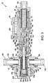
Fig. 1 is a cross-section view of an exemplary heater valve where a thermal spool and a priority spool are both in a first position; -
Fig. 2 is a cross-section view of the heater valve where the thermal spool is in the first position and the priority spool is in a second position; -
Fig. 3 is a cross-section view of the heater valve where the thermal spool is in a second position and the priority spool is in the second position; -
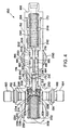
Fig. 4 is a cross-sectional view of another heater valve where a thermal spool and a priority spool are both in a first position; -
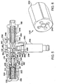
Fig. 5 is another cross-sectional view of the heater valve ofFig. 4 ; and -
Fig. 6 is a perspective view of an exemplary priority spring seat. - Referring to the drawings,
Fig. 1 shows aheater valve 10 which includes avalve housing 12 having aninlet 14, afirst outlet 16 and asecond outlet 18. Theinlet 14 is configured to receive aninlet port 20, which is secured to the housing by any suitable means, such as by threads, and sealed by a suitable seal, such as an o-ring 24. It will be appreciated, however, that the inlet port may be formed integrally with the housing. Alocking ring 22 disposed around theinlet port 20 is provided to prevent loosening of the inlet port, and the locking ring may be secured to the housing by any suitable means, such as by threads. Theinlet port 20 may be coupled to a supply line to receive fluid, such as high pressure hydraulic fluid from the supply line. Alternatively, the supply line may be directly coupled to the inlet. - The
first outlet 16 is configured to receive afirst outlet port 26, which is secured to the housing by any suitable means, such as by threads, and sealed by a suitable seal, such as o-ring 30. It will be appreciated, however, that the first outlet port may be formed integrally with the housing. Alocking ring 28 disposed around theoutlet port 26 is provided to prevent loosening of the outlet port, and the locking ring may be secured to the housing by any suitable means, such as by threads. Thefirst outlet port 26 receives fluid from the inlet port and may be coupled to a distribution line to deliver the fluid downstream of thevalve 10. Alternatively, the distribution line may be directly coupled to the first outlet. Thesecond outlet 18 is configured to receive asecond outlet port 32, which is secured to the housing by any suitable means, such as by threads, and sealed by a suitable seal, such as an o-ring 34. It will be appreciated, however, that the second outlet port may be formed integrally with the housing. Thesecond outlet port 32 is configured to receive fluid from the inlet port and may be coupled to a fluid reservoir to deliver the fluid to the reservoir. Alternatively, the fluid reservoir may be directly coupled to the second outlet. - The
valve 10 also includes asleeve 42 assembled in the housing, which may alternatively be integrally formed with the housing, athermal valve member 44 and apriority valve member 46, the valve members being preferably in the form of spools guided in the sleeve and will herein be described as such. Thesleeve 42 includesfirst openings 48 andsecond openings 50 connected by anannulus 52 andthird openings 54 configured to communicate with anannulus 56 of thepriority spool 46 and with aflow passage 58 in the housing. The sleeve is sealed to an inner wall of thehousing 10 by suitable seals, such as o-ring 60 and back-uprings ring 66 and back-uprings ring 60, and o-ring 72 and back-uprings ring 66. Thethermal spool 44 includesfirst openings 78 communicating with apassage 80 between the inlet and the first outlet,second openings 82 communicating with anannulus 83 on an outside of the thermal spool that communicates with thefirst openings 48 in thesleeve 42 when the thermal spool is in a first position, and a third opening 84 on a first end for receiving fluid. Thethermal spool 44 also includes ahollow bore 86 allowing fluid to flow out of a second end of thethermal spool 44 to contact apressure surface 88 of thepriority spool 46, which may be an end face. The pressure acting on theend face 88 can shift thepriority spool 46 to a second position. - The
thermal spool 44 is balanced by first andsecond springs first spring 90 may be any suitable spring, such as a corrosion-resistant steel spring and thesecond spring 92 may be any suitable spring responsive to temperature changes of the fluid flowing through the housing, such as a nickel titanium (nitinol) spring. Alternatively, the first spring or both the first and second springs may be nickel titanium springs responsive to different temperatures. - The
first spring 90 surrounds thethermal spool 44 and is interposed between a lip on the first end of thethermal spool 44 and an end wall of a counterbore of thesleeve 42. Thesecond spring 92 surrounds athermal spring seat 94, which hasopenings 96 and anopening 98 on a first end for receiving fluid. Thesecond spring 90 is interposed between an end wall of a counterbore of acap 100 and a lip of thespring seat 94. When thevalve 10 is assembled, thesleeve 42,thermal spool 44 andpriority spool 46 are inserted into the housing on a first side of the housing, with thespring 90 surrounding the thermal spool, and thethermal spring seat 94 is inserted over thethermal spool 44 so that a first end of the thermal spool abuts an end wall of a counterbore of thespring seat 94. Alternatively, the priority spool can be inserted from a second side of the housing separately from the thermal spool and the sleeve. Thecap 100 is then secured to thehousing 12 by any suitable means, such as byretainer wire 102, to hold thethermal spool 44,spring 92 andspring seat 94 in place. Thecap 100 is sealed to an inner wall of thehousing 12 by suitable seals, such as o-ring 104 and back-uprings - The
valve 10 also includes athird spring 110 biasing the priority spool in a first position, which as illustrated is a closed position. Thespring 110 may be any suitable spring, such as a corrosion-resistant steel spring or a nickel titanium spring. Thespring 110 is interposed between an end wall of a counterbore of apriority spring seat 112 and an end wall of a counterbore of thesecond outlet port 32. Thespring seat 112 includesopenings 114 on a first end for receiving fluid that flows from apassage 116 to apassage 118 in the housing. - When fluid is flowing through the
valve 10 from theinlet port 20 towards thefirst outlet port 26, or from the first outlet port to the inlet port, the fluid flows over thethermal spool 44 and thethermal spring seat 94. Some of the fluid enters thespring seat 94 viaopenings 96 and opening 98 and thethermal spool 44 via thefirst openings 78 and the third opening 84, and some of the fluid flows out thefirst outlet port 26. The fluid in thethermal spool 44 andspring seat 94 flows towards thesecond openings 82 in thethermal spool 44. When the thermal spool is in the first position, as shown inFigs. 1 and2 as an open position, theopenings 82 andannulus 83 are aligned with thefirst openings 48 in thesleeve 42. The fluid flows through theopenings 48 towards theannulus 52 on an outside of thesleeve 42. The fluid flows along theannulus 52 and into thesleeve 42 via thesecond openings 50, and then through the sleeve along theannulus 56 on an outside of thepriority spool 46. When thepriority spool 46 is in a second position, as shown inFigs. 2 and3 as an open position, the fluid flows along theannulus 56 to theopenings 54 in thesleeve 42. Theopenings 54 are in line with theflow passage 58 in the housing. - Turning now to the operation of the
valve 10.Fig. 1 shows thethermal spool 44 in the first position and thepriority spool 46 in the first position. Thethermal spool 44 is in the first position when the temperature of the fluid is below a predetermined temperature, for example, less than 20°C, and thepriority spool 46 is in the first position when the pressure of the fluid is below a predetermined pressure, for example, less than 25 MPa (250 bar). When the temperature is below the predetermined temperature, the spring force of thefirst spring 90 is greater than the spring force of thesecond spring 92, thereby causing thethermal spool 44 to be shifted to the first position by thefirst spring 90. - As mentioned above, as the fluid flows over
thermal spool 44,spring seat 94, and first andsecond springs thermal spool 44 andspring seat 94 via theopenings thermal spool 44 and exits the spool viaopenings 82 and theannulus 83, which are aligned with thefirst openings 48 in thesleeve 42. The fluid flows from thefirst openings 48 to theannulus 52 and then along the annulus to thesecond openings 50 in thesleeve 42. The fluid then flows from theopenings 50 to theannulus 56 on thepriority spool 46 and along the annulus. However, because the pressure of the fluid is below the predetermined pressure, thepriority spool 46 is in the first position and theannulus 56 is not aligned with theopenings 54 in the sleeve. Therefore, the fluid does not enter theflow passage 58 and only exits thevalve 10 via thefirst outlet port 26. - Turning now to the operation of the
valve 10 shown inFig. 2 , thethermal spool 44 is shown in the first position and thepriority spool 46 is shown in the second position. Thepriority spool 46 is in the second position when the pressure of the fluid is above the predetermined pressure, for example, greater than 25 MPa (250 bar). Thepriority spool 46 is moved to the second position by the fluid flowing through thebore 86 of thethermal spool 44. When the pressure of the fluid entering thevalve 10 is above the predetermined pressure, the pressure of the fluid flowing through thebore 86 acts on theend face 88 to shift thepriority spool 46 towards thesecond outlet port 32 to the second position so that theannulus 56 is aligned with theopenings 54. Thepriority spool 46 therefore overcomes the spring force of thespring 110 that is biasing thepriority spool 46 in the first position, and the fluid flows from theopenings 54 to theflow passage 58. - The fluid then flows from the
flow passage 58 to aheating orifice 120, where the fluid will increase in temperature and experience a pressure drop. The now low pressure, high temperature fluid exits theheating orifice 120 and flows to theflow passage 116 and then to thepassage 118. The fluid enters thepassage 118 and flows around thepriority spring seat 112 and into the spring seat viaopenings 114 on the first end of the spring seat. The fluid then flows through thespring seat 112 and out thesecond outlet port 32 to a fluid reservoir. Accordingly, as shown inFig. 2 , fluid having a temperature below the predetermined temperature and a pressure above the predetermined pressure flows out thefirst outlet port 26, while fluid having a temperature above the predetermined temperature and a pressure below the predetermined pressure flows out thesecond outlet port 32. In this way, high temperature fluid can be returned to the reservoir via the second outlet port so that when the fluid is re-circulated through thevalve 10, the fluid has a higher temperature and therefore prevents or reduces pressure drops downstream of thevalve 10. With pressure drops being prevented or reduced, smaller hydraulic lines may be used in the airplane, thereby reducing the weight of the airplane. Moreover, because the fluid flowing through the lines will be at a higher temperature, the valve allows for faster response of flight control actuators on the aircraft. - Turning now to
Fig. 3 , thethermal spool 44 is shown in a second position and thepriority spool 46 is shown in the second position. Thethermal spool 44 is in the second position, which as shown is a closed position, when the temperature of the fluid is above the predetermined temperature, for example, greater than 30°C. If the thermal spool is configured to be in the first position at a first temperature and a second position at a second temperature (for example, if the thermal spool is in the first position at a temperature less than 20°C and the second position at a temperature greater than 30°C), the thermal spool may be in a partially open/closed position between the two temperatures. - As the fluid at a temperature above the predetermined temperature flows over the first and
second springs second spring 92 reacts to the temperature of the fluid and the spring force of thesecond spring 92 increases to a spring force greater than the spring force of thefirst spring 90. Thesecond spring 92 then shifts thethermal spool 44 to the second position towards thepriority spool 46. In the second position, thesecond openings 82 andannulus 83 in thethermal spool 44 no longer are aligned with theopenings 50 in thesleeve 42. Therefore, even though the pressure of the fluid is above the predetermined pressure, resulting in thepriority spool 46 being in the second position so that theannulus 56 is aligned with theopenings 54, the fluid does not flow to theannulus 56. Accordingly, the fluid does not enter theflow passage 58 and therefore only exits thevalve 10 via thefirst outlet port 26. -
Figs. 4 and5 show aheater valve 150 which is substantially the same as theheater valve 10 discussed above, and accordingly, the foregoing description of theheater valve 10 is equally applicable to theheater valve 150 except as noted below. - The heater valve includes a
housing 152 having aninlet 154, afirst outlet 156 and asecond outlet 158. Theinlet 154 is configured to receive aninlet port 160, which is secured to the housing by any suitable means, such as by threads, and sealed by a suitable seal. It will be appreciated, however, that the inlet port may be formed integrally with the housing. A lockingring 162 disposed around theinlet port 160, and the locking ring may be secured to the housing by any suitable means, such as by threads. Thefirst outlet 156 is configured to receive afirst outlet port 164, which is secured to the housing by any suitable means, such as by threads, and sealed by a suitable seal. It will be appreciated, however, that the first outlet port may be formed integrally with the housing. A lockingring 166 disposed around theoutlet port 164 is provided to prevent loosening of the outlet port, and the locking ring may be secured to the housing by any suitable means, such as by threads. Thesecond outlet 158 is configured to receive asecond outlet port 168, which is secured to the housing by any suitable means, such as by threads, and sealed by a suitable seal, such as o-ring 170. It will be appreciated, however, that the second outlet port may be formed integrally with the housing. - The
valve 150 also includessleeve 174, which may be integrally formed with the housing, athermal valve member 176 and apriority valve member 178, the valve members being preferably in the form of spools guided in the sleeve and will herein be described as such. Thesleeve 174 includesfirst openings 180 andsecond openings 182 connected by anannulus 184 andthird openings 186 configured to communicate with anannulus 188 of thepriority spool 178 and with aflow passage 190 in the housing. Thesleeve 174 is sealed to an inner wall of thehousing 150 by suitable seals, such as o-ring 192 and back-uprings ring 196 and back-uprings ring 202 and back-up rings 204 and 206 downstream of o-ring 196. Thethermal spool 176 includesfirst openings 208 communicating with a passage 210 between the inlet and the first outlet,second openings 212 communicating with an annulus 213 on an outside of the thermal spool that communicates with thefirst openings 180 in thesleeve 174 when the thermal spool is in a first position, and athird opening 214 for receiving fluid. Thethermal spool 174 also includes ahollow bore 216 allowing fluid to flow through the thermal spool to contact apressure surface 218 of thepriority spool 178, which may be an end face. The pressure acting on theend face 218 can shift thepriority spool 178 to a second position. - The
thermal spool 176 is balanced by first andsecond springs first spring 220 may be any suitable spring, such as a corrosion-resistant steel spring and thesecond spring 222 may be any suitable spring responsive to temperature changes of the fluid flowing through the housing, such as a nickel titanium (nitinol) spring. Alternatively, the first spring or both the first and second springs may be nickel titanium springs responsive to different temperatures. - The
first spring 220 surrounds athermal spring seat 224, which hasopenings 226 and anopening 228 on a first end for receiving fluid. Thespring 220 is interposed between lip of thespring seat 224 and a retainingring 230. Theretainer ring 230 has an opening through which the thermal spool is inserted and is disposed upstream of the lip of thespring seat 224 and adjacent a first end of thesleeve 174. Thesecond spring 222 is interposed between an end wall of a counterbore of acap 232 and awasher 234 disposed on an end wall of a counterbore of thespring seat 224. The washer has anopening 235 through which fluid flows and thethermal spool 178 is mechanically interlocked into thesleeve 174 via thewasher 234. When thevalve 150 is assembled, thesleeve 174 andpriority spool 178 are inserted into thevalve housing 152 on a first side of the housing. Alternatively, the priority spool can be inserted from a second side of the housing. The retainingring 230 and thefirst spring 220 are then inserted into the housing. Thethermal spool 176 andwasher 234 are inserted into thespring seat 224, before being inserted into the housing, and thespring seat 224 is inserted so that the lip on the spring seat abuts the first end of thespring 220. Thesecond spring 222 can then be inserted into the spring seat, or alternatively already be disposed in the spring seat, and thecap 232 secured to thehousing 152 by any suitable means, such as threads. Thecap 232 is sealed to an inner wall of thehousing 152 by suitable seals, such as o-ring 236 and back-upring 238. - The
valve 150 also includes athird spring 240 biasing the priority spool in a first position, which as illustrated is a closed position. Thespring 240 may be any suitable spring, such as a corrosion-resistant steel spring or a nickel titanium spring. Thespring 240 is interposed between an end wall of a counterbore of apriority spring seat 242 and an end wall of a counterbore of thesecond outlet port 168. Thespring seat 242 includes openings 244 (Fig. 6 ) on a first end for receiving fluid that flows from apassage 246 to apassage 248 in the housing. - When fluid is flowing through the
valve 150 from theinlet port 160 towards thefirst outlet port 164, or from the first outlet port to the inlet port, the fluid flows over thethermal spool 176 and thethermal spring seat 224. Some of the fluid enters thespring seat 224 viaopenings 226 andopening 228 and thethermal spool 176 via thefirst openings 208 and thethird opening 214. The fluid in thethermal spool 176 andspring seat 224 flows towards thesecond openings 212 in the thermal spool. When thethermal spool 176 is in the first position, as shown inFigs. 4 and5 as an open position, theopenings 212 and annulus 213 are aligned with thefirst openings 180 in thesleeve 174. The fluid flows through theopenings 180 towards theannulus 184 on an outside of thesleeve 174. The fluid flows along theannulus 184 and into thesleeve 174 via thesecond openings 182, and then though the sleeve along theannulus 188 on an outside of thepriority spool 178. - When the
priority spool 178 is in a second position, which is an open position similar toFigs. 2 and3 , the fluid flows along theannulus 188 to theopenings 186 in thesleeve 174 and then to theflow passage 190 and out thesecond outlet 168. The priority spool is moved to the second position by the fluid flowing through thebore 216 of the thermal spool. When the pressure of the fluid entering thevalve 150 is above the predetermined pressure, the pressure of the fluid flowing through thebore 216 acts on theend face 218 of thepriority spool 178 to shift the priority spool to the second position so that theannulus 188 is aligned with theopenings 186. The fluid then flows from theflow passage 190 to aheating orifice 250, where the fluid will increase in temperature and experience a pressure drop. The low pressure, high temperature fluid exiting the heating orifice then flows to theflow passage 246 that communicates with thepassage 248 in thehousing 152. The fluid enters thepassage 248 and flows around thepriority spring seat 242 viagrooves 252, shown inFig. 6 , on an outer surface of the spring seat. The fluid can flow into the spring seat viaopenings 244, shown inFig. 6 , on a first end of the spring seat, and can also flow along thegrooves 252 towards thesecond outlet port 168. The fluid then flow around and through thespring seat 242, and out of thesecond outlet port 168 to a fluid reservoir. Accordingly, the fluid flows out of thevalve 150 via bothoutlet ports - As best shown in
Fig. 5 , theheater valve 150 also includes apressure sensor 256, which may be a pressure switch. The pressure sensor is provided to sense the pressure in a passage downstream of the thermal valve. The pressure sensor can therefore determine when both thethermal spool 176 and thepriority spool 178 are open to detect when theheater valve 150 is heating fluid and when the valve is not heating fluid. The housing includes anopening 258 configured to receive a first end of thepressure sensor 256. The pressure sensor is held in place by acollar 260 and sealed by suitable seals, such as o-ring 262 and back-uprings collar 260 is secured to the housing by any suitable means, such as by threads. A second end of the pressure switch is configured to be coupled to the aircraft so that the pressure switch can be connected to an aircraft signal wire. - The invention also provides a valve assembly including a housing having an inlet for receiving fluid and first and second outlets for delivering the fluid from the valve assembly, and thermal and priority valve members shiftable in the housing, the thermal valve member being shiftable by first and second springs between a first position permitting fluid flow from the inlet to the priority valve member and a second position blocking fluid flow, at least one of the springs being responsive to temperature changes of the fluid flowing through the housing, and the priority valve member being shiftable against a biasing force by pressure at the inlet above a predetermined pressure, the priority valve member being shiftable between a first position blocking flow from the inlet to the second outlet and a second position permitting flow.
- Optionally, the first and second springs shift the thermal valve member to the first position when a temperature of the fluid is below a predetermined temperature and to the second position when the temperature of the fluid is above the predetermined temperature.
- Optionally, the priority valve member is shifted to the first position when the pressure of the fluid is below the predetermined pressure and to the second position when the pressure of the fluid is above the predetermined pressure.
- Optionally, the thermal valve member has a bore allowing fluid to flow through the thermal valve member to act on an end face of the priority valve member to shift the priority valve member to the second position.
- Optionally, the valve assembly includes a third spring for effecting the biassing force on the priority valve member.
- Optionally, the third spring is seated against a priority spring seat, and wherein movement of the priority valve member to the second position shifts the spring seat from a first position to a second position to allow the fluid to flow to the second outlet.
- Optionally, the valve assembly includes a sleeve disposed in the housing that guides the thermal and priority valve members, wherein the sleeve includes a first opening for receiving fluid from the thermal valve member when the thermal valve member is in the first position, a second opening communicating with the first opening, a third opening communicating with the second opening, and an annulus communicating with the first and second openings.
- Optionally, the thermal valve member includes a first opening for receiving fluid and a second opening for delivering fluid to the first opening in the sleeve when the thermal valve member is in the first position.
- Optionally, the priority valve member includes an annulus communicating with the second and third openings in the sleeve when the priority valve member is in the second position.
- Optionally, the valve assembly includes a heating orifice disposed between the inlet and the second outlet, wherein fluid passing through the heating orifice will increase in temperature.
- Preferably, the thermal and priority valve members are axially which can shift spools.
- Optionally, the at least one spring responsive to temperature change has a spring force that increases when the fluid temperature is above the predetermined temperature to overcome a spring force of the other spring.
- Optionally, the at least one spring responsive to temperature changes of the fluid is a nickel titanium spring.
- Optionally, the first and second springs are concentric.
- Optionally, the first and second springs are in a path of the fluid from the inlet to the first outlet.
- Optionally, the valve assembly includes a pressure sensor for sensing pressure in a passage downstream of the thermal valve member.
- The invention also provides a method of delivering fluid through a valve assembly, the valve assembly including a housing and thermal and priority valve members shiftable in the housing, wherein the thermal valve member is balanced by first and second springs, and wherein at least one of the springs is responsive to temperature changes of the fluid flowing through the housing, the method including, receiving fluid at an inlet of the housing, delivering the fluid to a first outlet of the housing, and delivering the fluid to a second outlet of the housing when the fluid has a temperature below a predetermined temperature and a pressure above a predetermined pressure.
- Optionally, prior to delivering the fluid to the second outlet, the method includes, heating the fluid in a heating orifice to a temperature above the predetermined temperature.
- Preferably, delivering the fluid to the second outlet includes, shifting the thermal valve member to a first position when the temperature of the fluid is below the predetermined temperature, and shifting the priority valve member to a second position when the pressure of the fluid is above the predetermined pressure.
Claims (15)
- A valve assembly including:a housing (12, 152) having an inlet (14, 154) for receiving fluid and first and second outlets (16, 156 and 18, 158) for delivering the fluid from the valve assembly; andthermal and priority valve members (44, 176 and 46, 178) which can shift in the housing (12, 152);the thermal valve member (44, 176) being which can shift by first and second springs (90, 220 and 92, 222) between a first position permitting fluid flow from the inlet (14, 154) to the priority valve member (46, 178) and a second position blocking fluid flow, at least one of the springs being responsive to temperature changes of the fluid flowing through the housing; andthe priority valve member (46, 178) being which can shift against a biassing force by pressure at the inlet (14, 154) above a predetermined pressure, the priority valve member (46, 178) being which can shift between a first position blocking flow from the inlet (14, 154) to the second outlet (18, 158) and a second position permitting flow.
- A valve assembly according to claim 1, wherein the first and second springs (90, 220 and 92, 222) shift the thermal valve member (44, 176) to the first position when a temperature of the fluid is below a predetermined temperature and to the second position when the temperature of the fluid is above the predetermined temperature.
- A valve assembly according to claim 1 or claim 2, wherein the priority valve member (46, 178) is shifted to the first position when the pressure of the fluid is below the predetermined pressure and to the second position when the pressure of the fluid is above the predetermined pressure.
- A valve assembly according to any preceding claim, wherein the thermal valve member (44, 176) has a bore (86, 216) allowing fluid to flow through the thermal valve member (44, 176) to act on an end face (88, 218) of the priority valve member (46, 178) to shift the priority valve member (46, 178) to the second position.
- A valve assembly according to any preceding claim, further including a third spring (110, 240) for effecting the biassing force on the priority valve member (46, 178), wherein the third spring (110, 240) is seated against a priority spring seat (112, 242), and wherein movement of the priority valve member (46, 178) to the second position shifts the spring seat (112, 242) from a first position to a second position to allow the fluid to flow to the second outlet (18, 158).
- A valve assembly according to any preceding claim, further including a sleeve (42, 174) disposed in the housing (12, 152) that guides the thermal and priority valve members (44, 176 and 46, 178), wherein the sleeve (42, 174) includes a first opening (48, 180) for receiving fluid from the thermal valve member (44, 176) when the thermal valve member (44, 176) is in the first position, a second opening (50, 182) communicating with the first opening (48, 180), a third opening (54, 186) communicating with the second opening (50, 182), and an annulus (52, 184) communicating with the first and second openings.
- A valve assembly according to claim 6, wherein the thermal valve member (44, 176) includes a first opening (78, 208) for receiving fluid and a second opening (82, 212) for delivering fluid to the first opening (48, 180) in the sleeve (42, 174) when the thermal valve member (44, 176) is in the first position.
- A valve assembly according to claim 6 or claim 7, wherein the priority valve member (46, 178) includes an annulus (56, 188) communicating with the second and third openings in the sleeve when the priority valve member (46, 178) is in the second position.
- A valve assembly according to any preceding claim, further including a heating orifice (120, 250) disposed between the inlet (14, 154) and the second outlet (18, 158), wherein fluid passing through the heating orifice (120, 250) will increase in temperature.
- A valve assembly according to any preceding claim, wherein the thermal and priority valve members (44, 176 and 46, 178) are axially shiftable spools.
- A valve assembly according to any preceding claim, wherein the at least one spring responsive to temperature change has a spring force that increases when the fluid temperature is above the predetermined temperature to overcome a spring force of the other spring.
- A valve assembly according to any preceding claim, wherein the first and second springs (90, 220 and 92, 222) are in a path of the fluid from the inlet (14, 154) to the first outlet (16, 156).
- A method of delivering fluid through a valve assembly, the valve assembly including a housing (12, 152) and thermal and priority valve members (44, 176 and 46, 178) shiftable in the housing (12, 152), wherein the thermal valve member (44, 176) is balanced by first and second springs (90, 220 and 92, 222), and wherein at least one of the springs is responsive to temperature changes of the fluid flowing through the housing, the method including:receiving fluid at an inlet (14, 154) of the housing (12, 152);delivering the fluid to a first outlet (16, 156) of the housing (12, 152); anddelivering the fluid to a second outlet (18, 158) of the housing (12, 152) when the fluid has a temperature below a predetermined temperature and a pressure above a predetermined pressure.
- A method according to claim 13, wherein prior to delivering the fluid to the second outlet (18, 158), the method includes heating the fluid in a heating orifice (120, 250) to a temperature above the predetermined temperature.
- A method according to claim 13 or 14, wherein delivering the fluid to the second outlet (18, 158) includes:shifting the thermal valve member (44, 176) to a first position when the temperature of the fluid is below the predetermined temperature; andshifting the priority valve member (46, 178) to a second position when the pressure of the fluid is above the predetermined pressure.
Applications Claiming Priority (2)
| Application Number | Priority Date | Filing Date | Title |
|---|---|---|---|
| US33289410P | 2010-05-10 | 2010-05-10 | |
| US13/072,850 US8881992B2 (en) | 2010-05-10 | 2011-03-28 | Hydraulic heater valve |
Publications (3)
| Publication Number | Publication Date |
|---|---|
| EP2437133A2 true EP2437133A2 (en) | 2012-04-04 |
| EP2437133A3 EP2437133A3 (en) | 2013-09-11 |
| EP2437133B1 EP2437133B1 (en) | 2020-09-16 |
Family
ID=44901132
Family Applications (1)
| Application Number | Title | Priority Date | Filing Date |
|---|---|---|---|
| EP11164630.3A Active EP2437133B1 (en) | 2010-05-10 | 2011-05-03 | Hydraulic heater valve |
Country Status (2)
| Country | Link |
|---|---|
| US (1) | US8881992B2 (en) |
| EP (1) | EP2437133B1 (en) |
Families Citing this family (4)
| Publication number | Priority date | Publication date | Assignee | Title |
|---|---|---|---|---|
| EP4414597A3 (en) * | 2013-03-15 | 2024-10-30 | RPM Industries, LLC | Valve assembly for machine fluid operations |
| EP3486163B1 (en) * | 2017-11-17 | 2020-02-26 | Airbus Operations GmbH | An actuating system for actuating a foldable wing tip portion of a wing for an aircraft |
| JP2022181783A (en) * | 2021-05-27 | 2022-12-08 | 株式会社山田製作所 | Combination valve device |
| US11989043B2 (en) | 2021-08-30 | 2024-05-21 | Kalsi Engineering, Inc. | Miniature passive thermal control valve for mixing or splitting single-phase fluid with adjustable thermal actuator |
Family Cites Families (30)
| Publication number | Priority date | Publication date | Assignee | Title |
|---|---|---|---|---|
| US1972170A (en) * | 1930-06-20 | 1934-09-04 | Spencer Thermostat Co | Valve |
| US2437961A (en) * | 1945-03-12 | 1948-03-16 | Garrett Corp Aires Mfg Company | Thermostatic shutter control and surge protection |
| US3378079A (en) * | 1965-10-01 | 1968-04-16 | John S. Page Jr. | Sleeve valve apparatus |
| US3575342A (en) * | 1969-06-20 | 1971-04-20 | Robertshaw Controls Co | Thermostatic valve construction and the like |
| US3783693A (en) | 1970-01-21 | 1974-01-08 | J Paros | Absolute pressure transducer |
| DE2323550C3 (en) * | 1973-05-10 | 1978-09-21 | Kloeckner-Humboldt-Deutz Ag, 5000 Koeln | Filling valve for a hydrodynamic unit |
| US4078722A (en) * | 1976-10-28 | 1978-03-14 | A. W. Cash Valve Manufacturing Corporation | Relief valve |
| US4354345A (en) * | 1980-04-29 | 1982-10-19 | United Technologies Corporation | Fuel heating system for gas turbine engine |
| US4344564A (en) * | 1981-02-23 | 1982-08-17 | Gould Inc. | Thermal by-pass valve with integral pressure relief |
| DE3109850A1 (en) * | 1981-03-14 | 1982-09-30 | Robert Bosch Gmbh, 7000 Stuttgart | CONTROL VALVE |
| US4634213A (en) | 1983-04-11 | 1987-01-06 | Raychem Corporation | Connectors for power distribution cables |
| US4489883A (en) * | 1984-01-19 | 1984-12-25 | General Motors Corporation | Temperature regulated dual pressure device |
| US4570851A (en) * | 1984-05-07 | 1986-02-18 | Cirillo John R | Temperature regulating, pressure relief flow valves employing shaped memory alloys |
| US5048751A (en) * | 1990-04-16 | 1991-09-17 | Outboard Marine Corporation | Pressure and temperature relief valve and diaphragm valve |
| US5205321A (en) * | 1991-11-21 | 1993-04-27 | M. C. Aerospace Corporation | Two-way hydraulic valve with one way time delay |
| US5228618A (en) * | 1991-11-26 | 1993-07-20 | Hydrotech Chemical Corporation | Thermal and flow regulator with integrated flow optimizer |
| US5873518A (en) * | 1997-03-17 | 1999-02-23 | Emerson Electric Co. | Water valve assembly having a temperature and pressure sensing device integrated therein |
| US6253837B1 (en) * | 1998-03-23 | 2001-07-03 | Long Manufacturing Ltd. | By-pass values for heat exchanger |
| US6536464B1 (en) | 2000-10-25 | 2003-03-25 | Grundfos Pumps Manufacturing Corporation | Thermostatically controlled bypass valve and water circulating system for same |
| US6935569B2 (en) * | 2001-08-31 | 2005-08-30 | Huron, Inc. | Oil cooler bypass valve |
| JP2004150535A (en) * | 2002-10-30 | 2004-05-27 | Jatco Ltd | Hydraulic adjusting valve |
| US7607285B2 (en) * | 2003-08-01 | 2009-10-27 | Honeywell International Inc. | Four mode thermal recirculation throttle valve |
| PT1676068E (en) * | 2003-09-25 | 2009-03-18 | Greens Ind Ltd | Temperature limiting device applicable to single lever valves for mixing hot and cold liquids |
| US7316227B2 (en) | 2005-02-01 | 2008-01-08 | Standard-Thomson Corporation | Temperature-controlled PCV valve |
| US7886987B2 (en) * | 2005-09-30 | 2011-02-15 | American Valve, Inc. | Products and process that act as a safety valve to prevent scalding |
| US7913926B2 (en) * | 2006-02-17 | 2011-03-29 | Watts Water Technologies, Inc. | Thermostatic mixing valve |
| US7735546B2 (en) * | 2006-10-20 | 2010-06-15 | Ford Global Technologies, Llc | Heat exchanger bypass valve having temperature insensitive pressure bypass function |
| GB0711629D0 (en) * | 2007-06-15 | 2007-07-25 | Honeywell Normalair Garrett Lt | Hydraulic heating apparatus |
| US8231064B2 (en) | 2007-07-02 | 2012-07-31 | Grundfos Pumps Corporation | Water control fixture having auxiliary functions |
| US8245946B2 (en) * | 2007-10-16 | 2012-08-21 | Nitroworks Corporation | Method and apparatus for conserving water |
-
2011
- 2011-03-28 US US13/072,850 patent/US8881992B2/en active Active
- 2011-05-03 EP EP11164630.3A patent/EP2437133B1/en active Active
Non-Patent Citations (1)
| Title |
|---|
| None |
Also Published As
| Publication number | Publication date |
|---|---|
| US8881992B2 (en) | 2014-11-11 |
| EP2437133B1 (en) | 2020-09-16 |
| EP2437133A3 (en) | 2013-09-11 |
| US20110272036A1 (en) | 2011-11-10 |
Similar Documents
| Publication | Publication Date | Title |
|---|---|---|
| EP2872958B1 (en) | Direct acting solenoid actuator | |
| US7921880B2 (en) | Three-way poppet valve with intermediate pilot port | |
| EP0698759B1 (en) | Excess flow valve | |
| CN105840847B (en) | Thermally Compensated Trim Components | |
| EP2437133B1 (en) | Hydraulic heater valve | |
| EP3246607B1 (en) | In-line shutoff valves | |
| EP3129660B1 (en) | Servo valve | |
| DE112010004226T5 (en) | Flow Control | |
| TW202022264A (en) | Electrohydraulic normally-open ventable valve configured to operate in pressure relief mode when actuated | |
| US9303779B2 (en) | Slam shut safety device with guided plug support | |
| US20130105720A1 (en) | Electro-Mechanical Three-Way Dual Seat Valve | |
| US10563675B2 (en) | Servovalve | |
| US9841119B2 (en) | Pilot valve arrangement | |
| US10655753B2 (en) | Hydraulic valve | |
| US20180157279A1 (en) | Electronic Fluid Metering Valve | |
| AU2018344825B2 (en) | A valve for controlling fluid flow, a fluid distribution system and a method for measuring differential pressure | |
| US20180195640A1 (en) | Solenoid valve | |
| US20170016553A1 (en) | Pilot valve | |
| CN106051249A (en) | Efficient speed-reducing flow speed control valve | |
| EP2748468B1 (en) | Manual override device for a twin spool valve | |
| US20150309515A1 (en) | Dual pressure shuttle valve | |
| EP2954243B1 (en) | Anti-cavitation throttle valve and method of operating the same | |
| US20080000534A1 (en) | Cartridge valve assembly | |
| US20140054387A1 (en) | Valve and valve system responsive to fluid temperature |
Legal Events
| Date | Code | Title | Description |
|---|---|---|---|
| PUAI | Public reference made under article 153(3) epc to a published international application that has entered the european phase |
Free format text: ORIGINAL CODE: 0009012 |
|
| AK | Designated contracting states |
Kind code of ref document: A2 Designated state(s): AL AT BE BG CH CY CZ DE DK EE ES FI FR GB GR HR HU IE IS IT LI LT LU LV MC MK MT NL NO PL PT RO RS SE SI SK SM TR |
|
| AX | Request for extension of the european patent |
Extension state: BA ME |
|
| PUAL | Search report despatched |
Free format text: ORIGINAL CODE: 0009013 |
|
| AK | Designated contracting states |
Kind code of ref document: A3 Designated state(s): AL AT BE BG CH CY CZ DE DK EE ES FI FR GB GR HR HU IE IS IT LI LT LU LV MC MK MT NL NO PL PT RO RS SE SI SK SM TR |
|
| AX | Request for extension of the european patent |
Extension state: BA ME |
|
| RIC1 | Information provided on ipc code assigned before grant |
Ipc: F16K 17/06 20060101ALI20130802BHEP Ipc: F16K 17/04 20060101ALI20130802BHEP Ipc: G05D 23/08 20060101AFI20130802BHEP Ipc: F16K 11/07 20060101ALI20130802BHEP Ipc: F16K 49/00 20060101ALI20130802BHEP |
|
| 17P | Request for examination filed |
Effective date: 20140305 |
|
| RBV | Designated contracting states (corrected) |
Designated state(s): AL AT BE BG CH CY CZ DE DK EE ES FI FR GB GR HR HU IE IS IT LI LT LU LV MC MK MT NL NO PL PT RO RS SE SI SK SM TR |
|
| STAA | Information on the status of an ep patent application or granted ep patent |
Free format text: STATUS: EXAMINATION IS IN PROGRESS |
|
| 17Q | First examination report despatched |
Effective date: 20170613 |
|
| GRAP | Despatch of communication of intention to grant a patent |
Free format text: ORIGINAL CODE: EPIDOSNIGR1 |
|
| STAA | Information on the status of an ep patent application or granted ep patent |
Free format text: STATUS: GRANT OF PATENT IS INTENDED |
|
| INTG | Intention to grant announced |
Effective date: 20200507 |
|
| GRAS | Grant fee paid |
Free format text: ORIGINAL CODE: EPIDOSNIGR3 |
|
| GRAA | (expected) grant |
Free format text: ORIGINAL CODE: 0009210 |
|
| STAA | Information on the status of an ep patent application or granted ep patent |
Free format text: STATUS: THE PATENT HAS BEEN GRANTED |
|
| AK | Designated contracting states |
Kind code of ref document: B1 Designated state(s): AL AT BE BG CH CY CZ DE DK EE ES FI FR GB GR HR HU IE IS IT LI LT LU LV MC MK MT NL NO PL PT RO RS SE SI SK SM TR |
|
| REG | Reference to a national code |
Ref country code: GB Ref legal event code: FG4D |
|
| REG | Reference to a national code |
Ref country code: CH Ref legal event code: EP |
|
| REG | Reference to a national code |
Ref country code: DE Ref legal event code: R096 Ref document number: 602011068600 Country of ref document: DE |
|
| REG | Reference to a national code |
Ref country code: IE Ref legal event code: FG4D |
|
| REG | Reference to a national code |
Ref country code: AT Ref legal event code: REF Ref document number: 1314713 Country of ref document: AT Kind code of ref document: T Effective date: 20201015 |
|
| PG25 | Lapsed in a contracting state [announced via postgrant information from national office to epo] |
Ref country code: FI Free format text: LAPSE BECAUSE OF FAILURE TO SUBMIT A TRANSLATION OF THE DESCRIPTION OR TO PAY THE FEE WITHIN THE PRESCRIBED TIME-LIMIT Effective date: 20200916 Ref country code: GR Free format text: LAPSE BECAUSE OF FAILURE TO SUBMIT A TRANSLATION OF THE DESCRIPTION OR TO PAY THE FEE WITHIN THE PRESCRIBED TIME-LIMIT Effective date: 20201217 Ref country code: SE Free format text: LAPSE BECAUSE OF FAILURE TO SUBMIT A TRANSLATION OF THE DESCRIPTION OR TO PAY THE FEE WITHIN THE PRESCRIBED TIME-LIMIT Effective date: 20200916 Ref country code: HR Free format text: LAPSE BECAUSE OF FAILURE TO SUBMIT A TRANSLATION OF THE DESCRIPTION OR TO PAY THE FEE WITHIN THE PRESCRIBED TIME-LIMIT Effective date: 20200916 Ref country code: NO Free format text: LAPSE BECAUSE OF FAILURE TO SUBMIT A TRANSLATION OF THE DESCRIPTION OR TO PAY THE FEE WITHIN THE PRESCRIBED TIME-LIMIT Effective date: 20201216 Ref country code: BG Free format text: LAPSE BECAUSE OF FAILURE TO SUBMIT A TRANSLATION OF THE DESCRIPTION OR TO PAY THE FEE WITHIN THE PRESCRIBED TIME-LIMIT Effective date: 20201216 |
|
| REG | Reference to a national code |
Ref country code: AT Ref legal event code: MK05 Ref document number: 1314713 Country of ref document: AT Kind code of ref document: T Effective date: 20200916 |
|
| REG | Reference to a national code |
Ref country code: NL Ref legal event code: MP Effective date: 20200916 |
|
| PG25 | Lapsed in a contracting state [announced via postgrant information from national office to epo] |
Ref country code: LV Free format text: LAPSE BECAUSE OF FAILURE TO SUBMIT A TRANSLATION OF THE DESCRIPTION OR TO PAY THE FEE WITHIN THE PRESCRIBED TIME-LIMIT Effective date: 20200916 Ref country code: RS Free format text: LAPSE BECAUSE OF FAILURE TO SUBMIT A TRANSLATION OF THE DESCRIPTION OR TO PAY THE FEE WITHIN THE PRESCRIBED TIME-LIMIT Effective date: 20200916 |
|
| REG | Reference to a national code |
Ref country code: LT Ref legal event code: MG4D |
|
| PG25 | Lapsed in a contracting state [announced via postgrant information from national office to epo] |
Ref country code: SM Free format text: LAPSE BECAUSE OF FAILURE TO SUBMIT A TRANSLATION OF THE DESCRIPTION OR TO PAY THE FEE WITHIN THE PRESCRIBED TIME-LIMIT Effective date: 20200916 Ref country code: RO Free format text: LAPSE BECAUSE OF FAILURE TO SUBMIT A TRANSLATION OF THE DESCRIPTION OR TO PAY THE FEE WITHIN THE PRESCRIBED TIME-LIMIT Effective date: 20200916 Ref country code: LT Free format text: LAPSE BECAUSE OF FAILURE TO SUBMIT A TRANSLATION OF THE DESCRIPTION OR TO PAY THE FEE WITHIN THE PRESCRIBED TIME-LIMIT Effective date: 20200916 Ref country code: NL Free format text: LAPSE BECAUSE OF FAILURE TO SUBMIT A TRANSLATION OF THE DESCRIPTION OR TO PAY THE FEE WITHIN THE PRESCRIBED TIME-LIMIT Effective date: 20200916 Ref country code: PT Free format text: LAPSE BECAUSE OF FAILURE TO SUBMIT A TRANSLATION OF THE DESCRIPTION OR TO PAY THE FEE WITHIN THE PRESCRIBED TIME-LIMIT Effective date: 20210118 Ref country code: CZ Free format text: LAPSE BECAUSE OF FAILURE TO SUBMIT A TRANSLATION OF THE DESCRIPTION OR TO PAY THE FEE WITHIN THE PRESCRIBED TIME-LIMIT Effective date: 20200916 Ref country code: EE Free format text: LAPSE BECAUSE OF FAILURE TO SUBMIT A TRANSLATION OF THE DESCRIPTION OR TO PAY THE FEE WITHIN THE PRESCRIBED TIME-LIMIT Effective date: 20200916 |
|
| PG25 | Lapsed in a contracting state [announced via postgrant information from national office to epo] |
Ref country code: ES Free format text: LAPSE BECAUSE OF FAILURE TO SUBMIT A TRANSLATION OF THE DESCRIPTION OR TO PAY THE FEE WITHIN THE PRESCRIBED TIME-LIMIT Effective date: 20200916 Ref country code: IS Free format text: LAPSE BECAUSE OF FAILURE TO SUBMIT A TRANSLATION OF THE DESCRIPTION OR TO PAY THE FEE WITHIN THE PRESCRIBED TIME-LIMIT Effective date: 20210116 Ref country code: AT Free format text: LAPSE BECAUSE OF FAILURE TO SUBMIT A TRANSLATION OF THE DESCRIPTION OR TO PAY THE FEE WITHIN THE PRESCRIBED TIME-LIMIT Effective date: 20200916 Ref country code: AL Free format text: LAPSE BECAUSE OF FAILURE TO SUBMIT A TRANSLATION OF THE DESCRIPTION OR TO PAY THE FEE WITHIN THE PRESCRIBED TIME-LIMIT Effective date: 20200916 Ref country code: PL Free format text: LAPSE BECAUSE OF FAILURE TO SUBMIT A TRANSLATION OF THE DESCRIPTION OR TO PAY THE FEE WITHIN THE PRESCRIBED TIME-LIMIT Effective date: 20200916 |
|
| REG | Reference to a national code |
Ref country code: DE Ref legal event code: R097 Ref document number: 602011068600 Country of ref document: DE |
|
| PG25 | Lapsed in a contracting state [announced via postgrant information from national office to epo] |
Ref country code: SK Free format text: LAPSE BECAUSE OF FAILURE TO SUBMIT A TRANSLATION OF THE DESCRIPTION OR TO PAY THE FEE WITHIN THE PRESCRIBED TIME-LIMIT Effective date: 20200916 |
|
| PLBE | No opposition filed within time limit |
Free format text: ORIGINAL CODE: 0009261 |
|
| STAA | Information on the status of an ep patent application or granted ep patent |
Free format text: STATUS: NO OPPOSITION FILED WITHIN TIME LIMIT |
|
| 26N | No opposition filed |
Effective date: 20210617 |
|
| PG25 | Lapsed in a contracting state [announced via postgrant information from national office to epo] |
Ref country code: SI Free format text: LAPSE BECAUSE OF FAILURE TO SUBMIT A TRANSLATION OF THE DESCRIPTION OR TO PAY THE FEE WITHIN THE PRESCRIBED TIME-LIMIT Effective date: 20200916 Ref country code: DK Free format text: LAPSE BECAUSE OF FAILURE TO SUBMIT A TRANSLATION OF THE DESCRIPTION OR TO PAY THE FEE WITHIN THE PRESCRIBED TIME-LIMIT Effective date: 20200916 |
|
| PG25 | Lapsed in a contracting state [announced via postgrant information from national office to epo] |
Ref country code: IT Free format text: LAPSE BECAUSE OF FAILURE TO SUBMIT A TRANSLATION OF THE DESCRIPTION OR TO PAY THE FEE WITHIN THE PRESCRIBED TIME-LIMIT Effective date: 20200916 |
|
| REG | Reference to a national code |
Ref country code: CH Ref legal event code: PL |
|
| PG25 | Lapsed in a contracting state [announced via postgrant information from national office to epo] |
Ref country code: CH Free format text: LAPSE BECAUSE OF NON-PAYMENT OF DUE FEES Effective date: 20210531 Ref country code: LI Free format text: LAPSE BECAUSE OF NON-PAYMENT OF DUE FEES Effective date: 20210531 Ref country code: MC Free format text: LAPSE BECAUSE OF FAILURE TO SUBMIT A TRANSLATION OF THE DESCRIPTION OR TO PAY THE FEE WITHIN THE PRESCRIBED TIME-LIMIT Effective date: 20200916 Ref country code: LU Free format text: LAPSE BECAUSE OF NON-PAYMENT OF DUE FEES Effective date: 20210503 |
|
| REG | Reference to a national code |
Ref country code: BE Ref legal event code: MM Effective date: 20210531 |
|
| PG25 | Lapsed in a contracting state [announced via postgrant information from national office to epo] |
Ref country code: IE Free format text: LAPSE BECAUSE OF NON-PAYMENT OF DUE FEES Effective date: 20210503 |
|
| PG25 | Lapsed in a contracting state [announced via postgrant information from national office to epo] |
Ref country code: BE Free format text: LAPSE BECAUSE OF NON-PAYMENT OF DUE FEES Effective date: 20210531 |
|
| PG25 | Lapsed in a contracting state [announced via postgrant information from national office to epo] |
Ref country code: HU Free format text: LAPSE BECAUSE OF FAILURE TO SUBMIT A TRANSLATION OF THE DESCRIPTION OR TO PAY THE FEE WITHIN THE PRESCRIBED TIME-LIMIT; INVALID AB INITIO Effective date: 20110503 Ref country code: CY Free format text: LAPSE BECAUSE OF FAILURE TO SUBMIT A TRANSLATION OF THE DESCRIPTION OR TO PAY THE FEE WITHIN THE PRESCRIBED TIME-LIMIT Effective date: 20200916 |
|
| P01 | Opt-out of the competence of the unified patent court (upc) registered |
Effective date: 20230524 |
|
| PG25 | Lapsed in a contracting state [announced via postgrant information from national office to epo] |
Ref country code: MK Free format text: LAPSE BECAUSE OF FAILURE TO SUBMIT A TRANSLATION OF THE DESCRIPTION OR TO PAY THE FEE WITHIN THE PRESCRIBED TIME-LIMIT Effective date: 20200916 |
|
| PG25 | Lapsed in a contracting state [announced via postgrant information from national office to epo] |
Ref country code: MT Free format text: LAPSE BECAUSE OF FAILURE TO SUBMIT A TRANSLATION OF THE DESCRIPTION OR TO PAY THE FEE WITHIN THE PRESCRIBED TIME-LIMIT Effective date: 20200916 |
|
| PGFP | Annual fee paid to national office [announced via postgrant information from national office to epo] |
Ref country code: DE Payment date: 20250529 Year of fee payment: 15 |
|
| PGFP | Annual fee paid to national office [announced via postgrant information from national office to epo] |
Ref country code: GB Payment date: 20250527 Year of fee payment: 15 |
|
| PGFP | Annual fee paid to national office [announced via postgrant information from national office to epo] |
Ref country code: FR Payment date: 20250526 Year of fee payment: 15 |
|
| PG25 | Lapsed in a contracting state [announced via postgrant information from national office to epo] |
Ref country code: TR Free format text: LAPSE BECAUSE OF FAILURE TO SUBMIT A TRANSLATION OF THE DESCRIPTION OR TO PAY THE FEE WITHIN THE PRESCRIBED TIME-LIMIT Effective date: 20200916 |
|
| REG | Reference to a national code |
Ref country code: DE Ref legal event code: R082 Ref document number: 602011068600 Country of ref document: DE Representative=s name: DIPAS PATENTANWALTS GMBH, DE |