EP2437077A1 - An MRI device with a plurality of individually controllable entry ports and inserts therefor - Google Patents
An MRI device with a plurality of individually controllable entry ports and inserts therefor Download PDFInfo
- Publication number
- EP2437077A1 EP2437077A1 EP11182715A EP11182715A EP2437077A1 EP 2437077 A1 EP2437077 A1 EP 2437077A1 EP 11182715 A EP11182715 A EP 11182715A EP 11182715 A EP11182715 A EP 11182715A EP 2437077 A1 EP2437077 A1 EP 2437077A1
- Authority
- EP
- European Patent Office
- Prior art keywords
- elongated enclosure
- input port
- cross
- sectional area
- elongated
- Prior art date
- Legal status (The legal status is an assumption and is not a legal conclusion. Google has not performed a legal analysis and makes no representation as to the accuracy of the status listed.)
- Granted
Links
Images



Classifications
-
- G—PHYSICS
- G01—MEASURING; TESTING
- G01R—MEASURING ELECTRIC VARIABLES; MEASURING MAGNETIC VARIABLES
- G01R33/00—Arrangements or instruments for measuring magnetic variables
- G01R33/20—Arrangements or instruments for measuring magnetic variables involving magnetic resonance
- G01R33/28—Details of apparatus provided for in groups G01R33/44 - G01R33/64
- G01R33/30—Sample handling arrangements, e.g. sample cells, spinning mechanisms
-
- A—HUMAN NECESSITIES
- A01—AGRICULTURE; FORESTRY; ANIMAL HUSBANDRY; HUNTING; TRAPPING; FISHING
- A01K—ANIMAL HUSBANDRY; AVICULTURE; APICULTURE; PISCICULTURE; FISHING; REARING OR BREEDING ANIMALS, NOT OTHERWISE PROVIDED FOR; NEW BREEDS OF ANIMALS
- A01K29/00—Other apparatus for animal husbandry
- A01K29/005—Monitoring or measuring activity
Definitions
- the present invention generally pertains to an MRI device with a plurality of individually controllable entry ports and inserts therefore, and to methods using the same.
- Magnetic resonance imaging (MRI), or nuclear magnetic resonance imaging (NMRI), is primarily a noninvasive medical imaging technique used in radiology to visualize detailed internal structure and limited function of the body.
- Objects to be analyzed are positioned within an MRI device in a predefined specific location and configuration. It is advantageous to adjust the location of the animal under inspection within the MRI device to obtain optimal analysis.
- Few patents pertain to means and methods of positioning analyzed objects. Hence for example, US Patent No.
- an RF coil positioning device for an MRI device in which a pallet is movably mounted on a mount and is moved by a drive means so that an RF coil unit mounted on the pallet is moved from its initial position at an imaging position in a magnetostatic field generator
- the coil positioning device comprising: coil detecting means provided at a predetermined position along a path of the pallet, for detecting the passage of the RF coil unit through a reference position on the path and generating a detection signal, the distance between the reference position and the imaging position being preknown; distance detecting means for detecting the distance of travel of the pallet; and drive control means supplied with signals from the coil detecting means and the distance detecting means, for controlling the drive means to move the pallet until the distance of its travel after the generation of the detection signal becomes equal to the distance from the reference position to the imaging position; wherein the coil detecting means is provided below the underside of the pallet.
- US patent discloses a diagnostic table for a medical imaging apparatus, the table comprising: a supporting unit; a tabletop movably supported by the supporting unit; a sliding command input device configured to receive a sliding command input, and generate a sliding command instruction corresponding to the sliding command input; a driving device configured to slidably move the tabletop in response to the sliding command instruction; a detector configured to detect actual sliding movement of the tabletop; a controller configured to compare the actual sliding movement of the tabletop with the sliding command instruction, the controller being configured to generate a fault condition instruction when the actual sliding movement of the tabletop is inconsistent with the sliding command instruction; and a stopper provided on the supporting unit and configured to be activated in response to the fault condition instruction in order to inhibit sliding movement of the tabletop.
- the MRI operator in those MRI systems can not routinely, quickly and easily switch between one object to another, and between one type of object to other object.
- US Patent No. 5490513 discloses a medical magnetic resonance imaging system comprising: (a) a magnet having an imaging volume and at least two apertures thereto, each of the apertures providing patient access to the imaging volume; (b) at least two patient handling systems, each of the patient handling systems comprising a motorized and remotely-controlled bed structure which accesses a respective one of the apertures of the magnet, each of the bed structures having means for positioning the breast region of a respective patient for a magnetic resonance imaging procedure in the imaging volume of the magnet; (c) a radio frequency antenna system for transmitting radio frequency energy into each of the respective patients when in the imaging volume, and detecting magnetic resonance imaging data from the breast region of each the patient; and (d) automatic patient sequence control means for automatically sequencing the transfer of the respective patients into and out of the imaging volume.
- US Patent No. 5623927 discloses a medical magnet resonance imaging system comprising: (a) a magnet having an imaging volume and at least two apertures, wherein each aperture is sufficiently large to provide patient access to the imaging volume; (b) at least two patient handling systems, with each of the patient handling systems comprising a moveable bed structure having means which provides access to one of the apertures of the magnet and with each of the moveable bed structures having means for receiving and positioning the breast region of a patient to be subjected to a magnetic resonance imaging procedure in the imaging volume of the magnet; (c) a radio frequency antenna system for transmitting radio frequency energy into a patient and detecting magnetic resonance imaging data from the breast region of each the patient. Scanned objects according to those patents are not maneuverable within the MRI device. Fine tuning of the various shape, size and type objects, especially in laboratory routine, wherein a frequent switching of scanned objects of different type shape and size is practically impossible utilizing those MRI systems.
- an MRD device including a first input port having a first cross-sectional area, and a second input port having second cross-sectional area, the first input port is substantially diametrically opposite the second input port.
- the first cross-sectional area is less than the second cross-sectional area.
- the first cross-sectional is different from the second cross-sectional area.
- an animal handling system for use in an MRD device including: a first elongated enclosure having a proximal end, a distal open end and a first geometry, and a second first elongated enclosure having a proximal end, a distal open end and a second geometry.
- the first second geometry includes a first cross-sectional area which is larger than a second cross-sectional area of the second geometry.
- the the first elongated enclosure is inserted into a first input port of the MRD device and the second elongated enclosure is inserted in a second input port of the MRD device diametrically opposite to second input port, such that on insertion of the first elongated enclosure into the first input port and insertion of the second elongated enclosure into the second input, the second elongated enclosure slides into the first elongated enclosure through the open distal end of the first elongated enclosure.
- the first elongated enclosure includes at least two portions the at least two portions are telescopic.
- the proximal end of the first elongated enclosure is sealed against a circumferential edge of the first input port and the proximal end of the second elongated enclosure is sealed against a circumferential edge of the second input port thereby sealing the first and second elongated enclosures from the outside environment.
- the first elongated enclosure includes a reaction testing device.
- the mammal is selected from the group consisting of a rodent, a cat, a dog, a rabbit and laboratory experimental animals.
- the term 'Magnetic Resonance Device' specifically applies hereinafter to any Magnetic Resonance Imaging (MRI) device, any Nuclear Magnetic Resonance (NMR) spectroscope, any Electron Spin Resonance (ESR) spectroscope, any Nuclear Quadruple Resonance (NQR) spectroscope or any combination thereof.
- the MRD hereby disclosed is optionally a portable MRI device, such as the ASPECT Magnet Technologies Ltd commercially available devices, or a commercially available non-portable device.
- the term 'MRD' generally refers in this patent to any medical device, at least temporary accommodating an anesthetized animal.
- animal generally refers in an interchangeable manner to any living creature, such as neonates, other mammal such as mice, rats, cats, dogs, rabbits etc and laboratory animals.
- object generally refers to items to be scanned, and include, in a non-limiting manner, laboratory items, such as microplates, microwells, tubes, veils, Eppendorf TM tubes and the like, animals, organs, tissues, reaction solutions, cell media, organic or inorganic matter and compositions thereof etc.
- the term “plurality” refers in a non-limiting manner to any integer equal or greater than 1.
- FIG. 1 schematically illustrating in an out of scale manner an MRD 100, here for example, a lab-scale MRI device, comprising two or more input ports 21 and 23.
- a plurality of mouse handling systems (MHS, 30, 40, Figs. 3- 4 and Figs. 5-6 , respectively) are reversibly inserted in the input ports, 21 and 22, respectively.
- the two MHS devices 30 and 40 are of different size and shape, and are adapted to be inserted and manipulated for different types of objects to be scanned.
- Fig. 1 shows that the MHS 30 has an ellipsoidal cross-section and the MHS 40 has a circular cross-section.
- the circular cross-sectional area of MHS 40 is less than the cross-sectional area of the MHS 30.
- both the MHS 30 and the MHS 40 are maneuverable elongated devices.
- Each one of the MHS' is characterized by a proximal end portion, which is located outside of the MRD 10 and possibly comprising an inserting abutment 41.
- the objects to be scanned are immobilized in a predefined configuration.
- the maneuverable MHS' 30 and 40 are rotatable about and translationally moveable parallel to the main longitudinal axis of shafts.
- the proximal portion 31 comprises, inter alia, at least one inner shaft 33a and at least one outer shaft 33b, both providing a telescopic maneuvering mechanism of the distal portion 32, located in proximity to an opening 21, within the MRI.
- the distal portion 32 is thus positioned, communicated with, and supplied with by means of the maneuverable proximal portion 31.
- Distal portion comprises a support 34, typically of ellipsoidal cross-section and includes a laboratory microplate 1.
- the microplate 1 includes, inter alia, a plurality micro-wells, which contain reaction media to be scanned.
- the distal portion 32 is at least partially covered by an MRI-compatible envelope 35, thereby preventing leakage of hazardous materials and fluids to flow outside of the MRI towards an MRI operator and the laboratory ambient environment.
- Fig. 4 similarly illustrating in an out of scale manner a detailed view of the MHS 30.
- Fig. 4 shows that the item to be scanned is a laboratory animal 2, such as, a rat.
- Fig. 5 schematically illustrating in an out of scale manner a detailed view of MHS 30 and MHS 40.
- the MRI device 10 is schematically presented by means of the two opposite input ports 21 and 22. It is acknowledged in this respect that multiple input ports can be located in a relatively opposite orientation or in a relatively perpendicular orientation.
- Fig. 5 shows the easy and quick manner in which different types of MHSs are interchangeable.
- MHS 30 is inserted in the MRI device 10 via the input port 21.
- the location of the distal portion 32 is controlled from the proximal portion 31.
- An elipsoidally-shaped cover 35 envelops an inner portion 33 of the MHS 30.
- the MHS 40 is inserted into input port 23 such that a distal portion 43 is located within an abutment 41 and coupled to the input port 22. The insertion of the MHS 40 into the MHS 30 is thus easily performed.
- FIG. 6 schematically illustrating in an out of scale manner a detailed view of MHS 40 having a circular cross section which is typically less than that of the cross-section of the MHS 30.
- the MHS 40 is inserted via input port 22 to within the MRI device 10.
- a proximal portion 42 manipulates a distal portion 43. It is noticeable that 43 is inserted and encapsulated by the envelope 35.
- An inserting abutment for MHS 30 seals input port 21.
Landscapes
- Life Sciences & Earth Sciences (AREA)
- Physics & Mathematics (AREA)
- Environmental Sciences (AREA)
- Condensed Matter Physics & Semiconductors (AREA)
- General Physics & Mathematics (AREA)
- Biophysics (AREA)
- Animal Husbandry (AREA)
- Biodiversity & Conservation Biology (AREA)
- Magnetic Resonance Imaging Apparatus (AREA)
Abstract
Description
- The present invention generally pertains to an MRI device with a plurality of individually controllable entry ports and inserts therefore, and to methods using the same.
- Magnetic resonance imaging (MRI), or nuclear magnetic resonance imaging (NMRI), is primarily a noninvasive medical imaging technique used in radiology to visualize detailed internal structure and limited function of the body.
- Objects to be analyzed are positioned within an MRI device in a predefined specific location and configuration. It is advantageous to adjust the location of the animal under inspection within the MRI device to obtain optimal analysis. Few patents pertain to means and methods of positioning analyzed objects. Hence for example,
US Patent No. 5066915 discloses an RF coil positioning device for an MRI device in which a pallet is movably mounted on a mount and is moved by a drive means so that an RF coil unit mounted on the pallet is moved from its initial position at an imaging position in a magnetostatic field generator, the coil positioning device comprising: coil detecting means provided at a predetermined position along a path of the pallet, for detecting the passage of the RF coil unit through a reference position on the path and generating a detection signal, the distance between the reference position and the imaging position being preknown; distance detecting means for detecting the distance of travel of the pallet; and drive control means supplied with signals from the coil detecting means and the distance detecting means, for controlling the drive means to move the pallet until the distance of its travel after the generation of the detection signal becomes equal to the distance from the reference position to the imaging position; wherein the coil detecting means is provided below the underside of the pallet. Likewise, US patent discloses a diagnostic table for a medical imaging apparatus, the table comprising: a supporting unit; a tabletop movably supported by the supporting unit; a sliding command input device configured to receive a sliding command input, and generate a sliding command instruction corresponding to the sliding command input; a driving device configured to slidably move the tabletop in response to the sliding command instruction; a detector configured to detect actual sliding movement of the tabletop; a controller configured to compare the actual sliding movement of the tabletop with the sliding command instruction, the controller being configured to generate a fault condition instruction when the actual sliding movement of the tabletop is inconsistent with the sliding command instruction; and a stopper provided on the supporting unit and configured to be activated in response to the fault condition instruction in order to inhibit sliding movement of the tabletop. The MRI operator in those MRI systems can not routinely, quickly and easily switch between one object to another, and between one type of object to other object. - Few patents disclose MRI devices with multiple apertures in the magnet structure.
Hence, US Patent No. 5490513 discloses a medical magnetic resonance imaging system comprising: (a) a magnet having an imaging volume and at least two apertures thereto, each of the apertures providing patient access to the imaging volume; (b) at least two patient handling systems, each of the patient handling systems comprising a motorized and remotely-controlled bed structure which accesses a respective one of the apertures of the magnet, each of the bed structures having means for positioning the breast region of a respective patient for a magnetic resonance imaging procedure in the imaging volume of the magnet; (c) a radio frequency antenna system for transmitting radio frequency energy into each of the respective patients when in the imaging volume, and detecting magnetic resonance imaging data from the breast region of each the patient; and (d) automatic patient sequence control means for automatically sequencing the transfer of the respective patients into and out of the imaging volume. Likewise,US Patent No. 5623927 discloses a medical magnet resonance imaging system comprising: (a) a magnet having an imaging volume and at least two apertures, wherein each aperture is sufficiently large to provide patient access to the imaging volume; (b) at least two patient handling systems, with each of the patient handling systems comprising a moveable bed structure having means which provides access to one of the apertures of the magnet and with each of the moveable bed structures having means for receiving and positioning the breast region of a patient to be subjected to a magnetic resonance imaging procedure in the imaging volume of the magnet; (c) a radio frequency antenna system for transmitting radio frequency energy into a patient and detecting magnetic resonance imaging data from the breast region of each the patient. Scanned objects according to those patents are not maneuverable within the MRI device. Fine tuning of the various shape, size and type objects, especially in laboratory routine, wherein a frequent switching of scanned objects of different type shape and size is practically impossible utilizing those MRI systems. - None of the above provides a simple solution for routine insertion of more than one maneuverable small and tangible objects, such as laboratory items (microplates laboratory animals etc), within a single lab-scale experimental MRI device. Hence an MRI device with a plurality of individually controllable entry ports and MRI-compatible inserts therefor fulfill a long felt need.
- It is thus one object of the invention to disclose an animal handling system
- There is provided in accordance with a preferred embodiment of the present invention an MRD device including a first input port having a first cross-sectional area, and a second input port having second cross-sectional area, the first input port is substantially diametrically opposite the second input port.
- Further in accordance with a preferred embodiment of the present invention, the first cross-sectional area is less than the second cross-sectional area.
- Still further in accordance with a preferred embodiment of the present invention the first cross-sectional is different from the second cross-sectional area.
- There is provided in accordance with another preferred embodiment of the present invention an animal handling system for use in an MRD device including: a first elongated enclosure having a proximal end, a distal open end and a first geometry, and a second first elongated enclosure having a proximal end, a distal open end and a second geometry. The first second geometry includes a first cross-sectional area which is larger than a second cross-sectional area of the second geometry. The the first elongated enclosure is inserted into a first input port of the MRD device and the second elongated enclosure is inserted in a second input port of the MRD device diametrically opposite to second input port, such that on insertion of the first elongated enclosure into the first input port and insertion of the second elongated enclosure into the second input, the second elongated enclosure slides into the first elongated enclosure through the open distal end of the first elongated enclosure.
- Further in accordance with another preferred embodiment of the present invention the first elongated enclosure includes at least two portions the at least two portions are telescopic.
- Still further in accordance with another preferred embodiment of the present invention the proximal end of the first elongated enclosure is sealed against a circumferential edge of the first input port and the proximal end of the second elongated enclosure is sealed against a circumferential edge of the second input port thereby sealing the first and second elongated enclosures from the outside environment.
- Additionally in accordance with another preferred embodiment of the present invention a mammal for experimenting is inserted into the second elongated enclosure. Furthermore in accordance with another preferred embodiment of the present invention the first elongated enclosure includes a reaction testing device.
- Further in accordance with another preferred embodiment of the present invention the mammal is selected from the group consisting of a rodent, a cat, a dog, a rabbit and laboratory experimental animals.
-
-
Fig. 1 shows an MRD device including two or more, in accordance with a preferred embodiment of the present invention; -
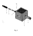
Fig. 2 shows the two Mouse Handling Systems (MHS), in accordance with a preferred embodiment of the present invention; -
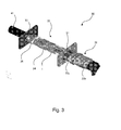
Figs. 3 and4 show the details of a view of the MHS device with an ellipsoidal cross-section; -
Figs. 5 and6 show the details of a view of the MHS device with a circular cross-section. - The following description is provided in order to enable any person skilled in the art to make use of the invention and sets forth the best modes contemplated by the inventor of carrying out this invention. Various modifications, however, will remain apparent to those skilled in the art, since the generic principles of the present invention have been defined specifically to provide means and methods for routine handling and scanning of items in a single MRD.
- The term 'Magnetic Resonance Device' (MRD) specifically applies hereinafter to any Magnetic Resonance Imaging (MRI) device, any Nuclear Magnetic Resonance (NMR) spectroscope, any Electron Spin Resonance (ESR) spectroscope, any Nuclear Quadruple Resonance (NQR) spectroscope or any combination thereof. The MRD hereby disclosed is optionally a portable MRI device, such as the ASPECT Magnet Technologies Ltd commercially available devices, or a commercially available non-portable device. Moreover, the term 'MRD' generally refers in this patent to any medical device, at least temporary accommodating an anesthetized animal.
- As used herein, the term "animal" or "mouse" generally refers in an interchangeable manner to any living creature, such as neonates, other mammal such as mice, rats, cats, dogs, rabbits etc and laboratory animals.
- As used herein, the term "object" generally refers to items to be scanned, and include, in a non-limiting manner, laboratory items, such as microplates, microwells, tubes, veils, Eppendorf TM tubes and the like, animals, organs, tissues, reaction solutions, cell media, organic or inorganic matter and compositions thereof etc.
- As used herein, the term "plurality" refers in a non-limiting manner to any integer equal or greater than 1.
- Reference is now made to
Fig. 1 , schematically illustrating in an out of scale manner anMRD 100, here for example, a lab-scale MRI device, comprising two ormore input ports Figs. 3- 4 andFigs. 5-6 , respectively) are reversibly inserted in the input ports, 21 and 22, respectively. The twoMHS devices - Reference is now made to
Fig. 2 , schematically illustrating in an out ofscale manner MHS 30 andMHS 40.Fig. 1 shows that theMHS 30 has an ellipsoidal cross-section and theMHS 40 has a circular cross-section. Typically, the circular cross-sectional area ofMHS 40 is less than the cross-sectional area of theMHS 30. According to the illustrated embodiment of the invention, both theMHS 30 and theMHS 40 are maneuverable elongated devices. Each one of the MHS' is characterized by a proximal end portion, which is located outside of theMRD 10 and possibly comprising aninserting abutment 41. At adistal end portion 43, the objects to be scanned are immobilized in a predefined configuration. The maneuverable MHS' 30 and 40 are rotatable about and translationally moveable parallel to the main longitudinal axis of shafts. - Reference is now made to
Fig. 3 , schematically illustrating in an out of scale manner a detailed view of theMHS 30. Theproximal portion 31 comprises, inter alia, at least oneinner shaft 33a and at least oneouter shaft 33b, both providing a telescopic maneuvering mechanism of thedistal portion 32, located in proximity to anopening 21, within the MRI. Thedistal portion 32 is thus positioned, communicated with, and supplied with by means of the maneuverableproximal portion 31. Distal portion comprises asupport 34, typically of ellipsoidal cross-section and includes a laboratory microplate 1. The microplate 1 includes, inter alia, a plurality micro-wells, which contain reaction media to be scanned. According to this embodiment of the invention, thedistal portion 32 is at least partially covered by an MRI-compatible envelope 35, thereby preventing leakage of hazardous materials and fluids to flow outside of the MRI towards an MRI operator and the laboratory ambient environment. - Reference is now made to
Fig. 4 , similarly illustrating in an out of scale manner a detailed view of theMHS 30.Fig. 4 shows that the item to be scanned is alaboratory animal 2, such as, a rat. - Reference is now made to
Fig. 5 , schematically illustrating in an out of scale manner a detailed view ofMHS 30 andMHS 40. TheMRI device 10 is schematically presented by means of the twoopposite input ports Fig. 5 shows the easy and quick manner in which different types of MHSs are interchangeable. As described above, and according to the aforesaid embodiment of the invention,MHS 30 is inserted in theMRI device 10 via theinput port 21. The location of thedistal portion 32 is controlled from theproximal portion 31. An elipsoidally-shapedcover 35 envelops aninner portion 33 of theMHS 30. TheMHS 40 is inserted intoinput port 23 such that adistal portion 43 is located within anabutment 41 and coupled to theinput port 22. The insertion of theMHS 40 into theMHS 30 is thus easily performed. - Reference is made to
Fig. 6 , schematically illustrating in an out of scale manner a detailed view ofMHS 40 having a circular cross section which is typically less than that of the cross-section of theMHS 30. TheMHS 40 is inserted viainput port 22 to within theMRI device 10. Aproximal portion 42 manipulates adistal portion 43. It is noticeable that 43 is inserted and encapsulated by theenvelope 35. An inserting abutment forMHS 30seals input port 21. - Hence, both means and methods for routine handling and scanning of items in a single MRI device is disclosed and presented.
- While the invention is susceptible to various modifications and alternative forms, specific embodiments thereof have been shown by way of example in the drawings and will herein be described in detail. It should be understood, however, that it is not intended to limit the invention to the particular forms disclosed, but on the contrary, the intention is to cover all modifications, equivalents, and alternatives falling within the spirit and scope of the invention as defined by the appended claims.
Claims (9)
- An MRD device comprising:a first input port having a first cross-sectional area, anda second input port having second cross-sectional area,wherein said first input port is substantially diametrically opposite said second input port.
- The MRD device according to claim 1, wherein said first cross-sectional area is less than said second cross-sectional area.
- The MRD device according to claim 1, wherein said first cross-sectional is different from said second cross-sectional area.
- An animal handling system for use in an MRD device comprising:a first elongated enclosure having a proximal end, a distal open end and a first geometry, anda second first elongated enclosure having a proximal end, a distal open end and a second geometry,wherein first second geometry comprises a first cross-sectional area which is larger than a second cross-sectional area of said second geometry, and
wherein said first elongated enclosure is inserted into a first input port of said MRD device and said second elongated enclosure is inserted in a second input port of said MRD device diametrically opposite to second input port, such that on insertion of said first elongated enclosure into said first input port and insertion of said second elongated enclosure into said second input, said second elongated enclosure slides into said first elongated enclosure through said open distal end of said first elongated enclosure. - The animal handling system according to claim 4, wherein said first elongated enclosure comprises at least two portions said at least two portions are telescopic.
- The animal handling system according to claim 4, wherein said proximal end of said first elongated enclosure is sealed against a circumferential edge of said first input port and said proximal end of said second elongated enclosure is sealed against a circumferential edge of said second input port thereby sealing the first and second elongated enclosures from the outside environment.
- The animal handling system according to claim 4, wherein a mammal for experimenting is inserted into said second elongated enclosure.
- The animal handling system according to claim 7, wherein said first elongated enclosure comprises a reaction testing device.
- The animal handling system according to claim 7, said mammal is selected from the group consisting of a rodent, a cat, a dog, a rabbit and laboratory experimental animals.
Priority Applications (1)
| Application Number | Priority Date | Filing Date | Title |
|---|---|---|---|
| EP14188947.7A EP2840409B1 (en) | 2010-09-30 | 2011-09-26 | A system comprising an MRI device with a plurality of individually controllable entry ports and inserts therefor |
Applications Claiming Priority (1)
| Application Number | Priority Date | Filing Date | Title |
|---|---|---|---|
| US38799210P | 2010-09-30 | 2010-09-30 |
Related Child Applications (2)
| Application Number | Title | Priority Date | Filing Date |
|---|---|---|---|
| EP14188947.7A Division EP2840409B1 (en) | 2010-09-30 | 2011-09-26 | A system comprising an MRI device with a plurality of individually controllable entry ports and inserts therefor |
| EP14188947.7A Division-Into EP2840409B1 (en) | 2010-09-30 | 2011-09-26 | A system comprising an MRI device with a plurality of individually controllable entry ports and inserts therefor |
Publications (2)
| Publication Number | Publication Date |
|---|---|
| EP2437077A1 true EP2437077A1 (en) | 2012-04-04 |
| EP2437077B1 EP2437077B1 (en) | 2015-03-04 |
Family
ID=45093314
Family Applications (2)
| Application Number | Title | Priority Date | Filing Date |
|---|---|---|---|
| EP14188947.7A Active EP2840409B1 (en) | 2010-09-30 | 2011-09-26 | A system comprising an MRI device with a plurality of individually controllable entry ports and inserts therefor |
| EP11182715.0A Active EP2437077B1 (en) | 2010-09-30 | 2011-09-26 | An MRI device with a plurality of individually controllable entry ports and inserts therefor |
Family Applications Before (1)
| Application Number | Title | Priority Date | Filing Date |
|---|---|---|---|
| EP14188947.7A Active EP2840409B1 (en) | 2010-09-30 | 2011-09-26 | A system comprising an MRI device with a plurality of individually controllable entry ports and inserts therefor |
Country Status (4)
| Country | Link |
|---|---|
| US (2) | US8807084B2 (en) |
| EP (2) | EP2840409B1 (en) |
| CN (1) | CN202801611U (en) |
| ES (1) | ES2537791T3 (en) |
Families Citing this family (55)
| Publication number | Priority date | Publication date | Assignee | Title |
|---|---|---|---|---|
| US9494540B2 (en) | 2006-08-21 | 2016-11-15 | Aspect Ai Ltd. | System and method for a nondestructive on-line testing of samples |
| US9061112B2 (en) | 2008-09-10 | 2015-06-23 | Aspect Imaging Ltd | Chamber for housing animals during anaesthetic procedures |
| IL196487A (en) | 2009-01-13 | 2016-03-31 | Aspect Imaging Ltd | Means for buying sharp resolution mri |
| WO2011001429A1 (en) | 2009-06-30 | 2011-01-06 | Aspect Magnet Technologies Ltd. | A cage in an mrd with a fastening/attenuating system |
| US20110234347A1 (en) * | 2010-03-24 | 2011-09-29 | Aspect Magnet Technologies Ltd. | Pole piece for permanent magnet mri systems |
| US11278461B2 (en) | 2010-07-07 | 2022-03-22 | Aspect Imaging Ltd. | Devices and methods for a neonate incubator, capsule and cart |
| US10191127B2 (en) | 2012-10-31 | 2019-01-29 | Aspect Imaging Ltd. | Magnetic resonance imaging system including a protective cover and a camera |
| US10076266B2 (en) | 2010-07-07 | 2018-09-18 | Aspect Imaging Ltd. | Devices and methods for a neonate incubator, capsule and cart |
| US9562956B2 (en) | 2012-10-31 | 2017-02-07 | Aspect Imaging Ltd. | Rotatable protective cover functioning as a door for MRI system |
| US10499830B2 (en) | 2010-07-07 | 2019-12-10 | Aspect Imaging Ltd. | Premature neonate life support environmental chamber for use in MRI/NMR devices |
| JP5194149B2 (en) | 2010-08-23 | 2013-05-08 | 東芝テック株式会社 | Store system and program |
| US9597246B2 (en) | 2010-09-16 | 2017-03-21 | Aspect Imaging Ltd. | Premature neonate closed life support system |
| US10794975B2 (en) | 2010-09-16 | 2020-10-06 | Aspect Imaging Ltd. | RF shielding channel in MRI-incubator's closure assembly |
| DE202011050130U1 (en) | 2010-09-27 | 2011-08-01 | Aspect Magnet Technologies Ltd. | Mask for analyzed mammals |
| US9655542B2 (en) | 2010-09-29 | 2017-05-23 | Aspect Imaging Ltd. | MRI with magnet assembly adapted for convenient scanning of laboratory animals with automated RF tuning unit |
| US10292617B2 (en) | 2010-09-30 | 2019-05-21 | Aspect Imaging Ltd. | Automated tuning and frequency matching with motor movement of RF coil in a magnetic resonance laboratory animal handling system |
| US8807084B2 (en) | 2010-09-30 | 2014-08-19 | Aspect Imaging Ltd. | MRI device with a plurality of individually controllable entry ports and inserts therefor |
| JP6021811B2 (en) | 2010-10-06 | 2016-11-09 | アスペクト イメージング リミテッド | Method for providing high resolution and high contrast combined MRI images |
| US9182461B2 (en) | 2012-06-06 | 2015-11-10 | Aspect Imaging Ltd. | High resolution high contrast MRI for flowing media |
| US9709652B2 (en) | 2012-10-07 | 2017-07-18 | Aspect Imaging Ltd. | MRI system with means to eliminate object movement whilst acquiring its image |
| US9864034B2 (en) | 2012-11-21 | 2018-01-09 | Aspect Imaging Ltd. | Method and system for a universal NMR/MRI console |
| US9551731B2 (en) | 2012-12-02 | 2017-01-24 | Aspect Imaging Ltd. | Gantry for mobilizing an MRI device towards static patients |
| US9155490B2 (en) | 2013-03-07 | 2015-10-13 | Aspect Imaging Ltd. | Integrated stethoscope-metal detector device |
| US9535141B2 (en) | 2013-03-13 | 2017-01-03 | Aspect Imaging Ltd. | MRI safety device means and methods thereof |
| EP3011369B1 (en) | 2013-06-20 | 2019-12-11 | Aspect International (2015) Private Limited | An nmr/mri-based integrated system for analyzing and treating of a drilling mud for drilling mud recycling process and methods thereof |
| DE202013104934U1 (en) | 2013-11-03 | 2014-01-09 | Aspect Imaging Ltd. | Patiententransportinkubator |
| US9557397B2 (en) | 2013-11-04 | 2017-01-31 | Aspect Imaging Ltd. | Method for manipulating the MRI's protocol of pulse-sequences |
| US9494503B2 (en) | 2013-11-06 | 2016-11-15 | Aspect Imaging Ltd. | Inline rheology/viscosity, density, and flow rate measurement |
| DE202013105212U1 (en) | 2013-11-17 | 2014-02-13 | Aspect Imaging Ltd. | Locking device of an MRI incubator |
| US10018692B2 (en) | 2013-11-20 | 2018-07-10 | Aspect Imaging Ltd. | Shutting assembly for closing an entrance of an MRI device |
| DE202013011370U1 (en) | 2013-12-18 | 2014-03-13 | Aspect Imaging Ltd. | RF shielding connection in an MRI locking device |
| US10386432B2 (en) | 2013-12-18 | 2019-08-20 | Aspect Imaging Ltd. | Radiofrequency shielding conduit in a door or a doorframe of a magnetic resonance imaging room |
| DE202015100024U1 (en) | 2014-01-29 | 2015-04-30 | Aspect Imaging Ltd. | Means for operating an MRI device in an RF magnetic environment |
| US10383782B2 (en) | 2014-02-17 | 2019-08-20 | Aspect Imaging Ltd. | Incubator deployable multi-functional panel |
| DE202014101104U1 (en) | 2014-03-09 | 2014-05-15 | Aspect Imaging Ltd. | A thermally insulating MRI sheath |
| DE202014101102U1 (en) | 2014-03-09 | 2014-04-01 | Aspect Imaging Ltd. | An RF shielding MRI sheath |
| DE202014101187U1 (en) | 2014-03-10 | 2014-03-26 | Aspect Imaging Ltd. | A mechanical coupling for an MRI |
| EP3143421A4 (en) | 2014-05-13 | 2018-04-04 | Aspect Imaging Ltd. | Protective and immobilizing sleeves with sensors, and methods for reducing the effect of object movement during MRI scanning |
| US11300531B2 (en) | 2014-06-25 | 2022-04-12 | Aspect Ai Ltd. | Accurate water cut measurement |
| DE202014104677U1 (en) | 2014-09-15 | 2014-10-22 | Aspect Ai Ltd. | Temperature controlled exchangeable NMR probe cassette |
| DE202014104679U1 (en) * | 2014-09-15 | 2014-10-08 | Aspect Ai Ltd. | An NMR extractable probe cassette |
| US10670574B2 (en) | 2015-01-19 | 2020-06-02 | Aspect International (2015) Private Limited | NMR-based systems for crude oil enhancement and methods thereof |
| CN106053299B (en) | 2015-04-12 | 2020-10-30 | 艾斯拜克特Ai有限公司 | NMR imaging of fluids in non-circular cross-section conduits |
| CN106324010A (en) | 2015-07-02 | 2017-01-11 | 艾斯拜克特Ai有限公司 | Analysis of fluids flowing in a conduit using MR equipment |
| US10655996B2 (en) | 2016-04-12 | 2020-05-19 | Aspect Imaging Ltd. | System and method for measuring velocity profiles |
| US11287497B2 (en) | 2016-08-08 | 2022-03-29 | Aspect Imaging Ltd. | Device, system and method for obtaining a magnetic measurement with permanent magnets |
| US11988730B2 (en) | 2016-08-08 | 2024-05-21 | Aspect Imaging Ltd. | Device, system and method for obtaining a magnetic measurement with permanent magnets |
| US10224135B2 (en) | 2016-08-08 | 2019-03-05 | Aspect Imaging Ltd. | Device, system and method for obtaining a magnetic measurement with permanent magnets |
| US11399732B2 (en) | 2016-09-12 | 2022-08-02 | Aspect Imaging Ltd. | RF coil assembly with a head opening and isolation channel |
| US11029378B2 (en) | 2016-12-14 | 2021-06-08 | Aspect Imaging Ltd. | Extendable radiofrequency shield for magnetic resonance imaging device |
| US10345251B2 (en) | 2017-02-23 | 2019-07-09 | Aspect Imaging Ltd. | Portable NMR device for detecting an oil concentration in water |
| US10401452B2 (en) | 2017-04-28 | 2019-09-03 | Aspect Imaging Ltd. | System for reduction of a magnetic fringe field of a magnetic resonance imaging device |
| WO2020109894A1 (en) | 2018-11-29 | 2020-06-04 | Epsitau Ltd. | Lightweight asymmetric magnet arrays |
| CN113366329A (en) | 2018-11-29 | 2021-09-07 | 爱普斯陶有限公司 | Lightweight asymmetric magnet array with mixed phase magnet rings |
| US10679781B1 (en) | 2018-11-29 | 2020-06-09 | Epsitau Ltd. | Lightweight asymmetric magnet arrays with theta magnet rings |
Citations (4)
| Publication number | Priority date | Publication date | Assignee | Title |
|---|---|---|---|---|
| US5066915A (en) | 1989-06-28 | 1991-11-19 | Siemens-Asahi Medical System, Ltd. | RF coil positioning device for MRI |
| US5490513A (en) | 1992-09-28 | 1996-02-13 | Fonar Corporation | Multiple patient breast scanning on a magnetic resonance imaging apparatus |
| US20050248349A1 (en) * | 2002-05-08 | 2005-11-10 | Michiya Okada | Supersensitive nuclear magnetic resonance imaging apparatus |
| US20060145698A1 (en) * | 2002-11-06 | 2006-07-06 | Griffin Adrian P | Apparatus for use in nmr system |
Family Cites Families (41)
| Publication number | Priority date | Publication date | Assignee | Title |
|---|---|---|---|---|
| US5167160A (en) * | 1991-06-05 | 1992-12-01 | Agmed, Inc. | Positioning device for presenting samples for electromagnetic analysis |
| US7414403B2 (en) * | 2003-07-31 | 2008-08-19 | Chiodo Chris D | Imaging machine / MRI positioning assembly for magnet coils and specimens at the sweet spot of an imaging field |
| WO2006020896A2 (en) * | 2004-08-13 | 2006-02-23 | The Regents Of The University Of California | Method and apparatus for animal positioning in imaging systems |
| US7865226B2 (en) * | 2006-02-03 | 2011-01-04 | Chiodo Chris D | Specimen positioning system for imaging machines |
| US7784429B2 (en) * | 2006-09-22 | 2010-08-31 | Chiodo Chris D | Contoured specimen holder for imaging machines |
| CN101808577B (en) * | 2007-05-24 | 2013-03-13 | 皇家飞利浦电子股份有限公司 | Small animal imaging capsule and bed system |
| CA2719839C (en) * | 2008-03-25 | 2017-08-22 | Visen Medical, Inc. | Animal holder for in vivo tomographic imaging with multiple modalities |
| CN102176946A (en) | 2008-08-12 | 2011-09-07 | 艾斯拜克特磁铁技术有限公司 | Systems and methods for anesthetizing and regulating body temperature in mammals |
| US9061112B2 (en) | 2008-09-10 | 2015-06-23 | Aspect Imaging Ltd | Chamber for housing animals during anaesthetic procedures |
| DE102008048414A1 (en) * | 2008-09-23 | 2010-04-15 | Bruker Biospin Ag | Apparatus and method for positioning a small animal for MRI measurement |
| US8327807B2 (en) * | 2008-10-17 | 2012-12-11 | Chiodo Chris D | Catheter and seal assembly |
| IL196487A (en) | 2009-01-13 | 2016-03-31 | Aspect Imaging Ltd | Means for buying sharp resolution mri |
| US9408682B2 (en) * | 2009-04-27 | 2016-08-09 | Rapid Biomedical Gmbh | Animal imaging holding device and method |
| WO2011001429A1 (en) | 2009-06-30 | 2011-01-06 | Aspect Magnet Technologies Ltd. | A cage in an mrd with a fastening/attenuating system |
| US20110234347A1 (en) | 2010-03-24 | 2011-09-29 | Aspect Magnet Technologies Ltd. | Pole piece for permanent magnet mri systems |
| WO2012004797A2 (en) | 2010-07-07 | 2012-01-12 | Aspect Magnet Technologies Ltd. | A premature neonate life support environmental chamber for use in mri/nmr devices |
| US9562956B2 (en) | 2012-10-31 | 2017-02-07 | Aspect Imaging Ltd. | Rotatable protective cover functioning as a door for MRI system |
| US9597246B2 (en) | 2010-09-16 | 2017-03-21 | Aspect Imaging Ltd. | Premature neonate closed life support system |
| DE202011051402U1 (en) | 2010-09-27 | 2011-11-25 | Aspect Magnet Technologies Ltd. | Microwells MRI readable markers |
| DE202011050130U1 (en) | 2010-09-27 | 2011-08-01 | Aspect Magnet Technologies Ltd. | Mask for analyzed mammals |
| DE202011051413U1 (en) | 2010-09-29 | 2012-01-09 | Aspect Magnet Technologies Ltd. | Magnetic resonance imaging with magnet arrangement for the practical scanning of experimental animals |
| US8807084B2 (en) | 2010-09-30 | 2014-08-19 | Aspect Imaging Ltd. | MRI device with a plurality of individually controllable entry ports and inserts therefor |
| US20130237803A1 (en) | 2010-11-16 | 2013-09-12 | Aspect Imaging Ltd. | System and Method for Generating Invasively Hyperpolarized Images |
| US20140103927A1 (en) | 2011-02-01 | 2014-04-17 | Uri Rapoport | Low-field magnetic resonance system (lf-mrs) for producing an mri image |
| US20130079624A1 (en) | 2011-09-23 | 2013-03-28 | Uri Rapoport | Graphical user interface for operating an mri |
| US9182461B2 (en) | 2012-06-06 | 2015-11-10 | Aspect Imaging Ltd. | High resolution high contrast MRI for flowing media |
| US20140051973A1 (en) | 2012-08-15 | 2014-02-20 | Aspect Imaging Ltd | Mri imaging system for generating a rendered image |
| US20140051974A1 (en) | 2012-08-15 | 2014-02-20 | Aspect Imaging Ltd. | System and method for mri imaging using polarized light |
| IL221491A (en) | 2012-08-15 | 2016-06-30 | Aspect Imaging Ltd | A magnetic resonance device integrated with a light field camera |
| US20140050827A1 (en) | 2012-08-15 | 2014-02-20 | Aspect Imaging Ltd. | Non-invasive mri system for analyzing quality of solid food products enveloped by flexible aluminum foil wrapper and methods thereof |
| US9709652B2 (en) | 2012-10-07 | 2017-07-18 | Aspect Imaging Ltd. | MRI system with means to eliminate object movement whilst acquiring its image |
| US20140128725A1 (en) | 2012-11-08 | 2014-05-08 | Aspect Imaging Ltd. | Neonate's incubator and mri docking-station |
| US9864034B2 (en) | 2012-11-21 | 2018-01-09 | Aspect Imaging Ltd. | Method and system for a universal NMR/MRI console |
| US20140142914A1 (en) | 2012-11-22 | 2014-05-22 | Aspect Imaging Ltd. | Means and methods of multidimensional modeling in vivo spatial image of an mri contrast agent |
| US9551731B2 (en) | 2012-12-02 | 2017-01-24 | Aspect Imaging Ltd. | Gantry for mobilizing an MRI device towards static patients |
| US20140152310A1 (en) | 2012-12-02 | 2014-06-05 | Aspect Imaging Ltd. | Gantry for mobilizing an mri device |
| US20140230850A1 (en) | 2013-02-20 | 2014-08-21 | Aspect Imaging Ltd. | Ramrod for mri and methods thereof |
| US9155490B2 (en) | 2013-03-07 | 2015-10-13 | Aspect Imaging Ltd. | Integrated stethoscope-metal detector device |
| US9535141B2 (en) | 2013-03-13 | 2017-01-03 | Aspect Imaging Ltd. | MRI safety device means and methods thereof |
| US20140300358A1 (en) | 2013-04-08 | 2014-10-09 | Aspect Imaging Ltd. | System and method for real-time noise reduction in mri data acquisition |
| DE202013105901U1 (en) | 2013-09-02 | 2014-02-11 | Aspect Imaging Ltd. | Incubator with double glazed wall |
-
2011
- 2011-09-23 US US13/241,367 patent/US8807084B2/en active Active
- 2011-09-26 EP EP14188947.7A patent/EP2840409B1/en active Active
- 2011-09-26 EP EP11182715.0A patent/EP2437077B1/en active Active
- 2011-09-26 ES ES11182715.0T patent/ES2537791T3/en active Active
- 2011-09-30 CN CN2011203697457U patent/CN202801611U/en not_active Expired - Lifetime
-
2014
- 2014-02-18 US US14/182,766 patent/US9681822B2/en not_active Expired - Fee Related
Patent Citations (5)
| Publication number | Priority date | Publication date | Assignee | Title |
|---|---|---|---|---|
| US5066915A (en) | 1989-06-28 | 1991-11-19 | Siemens-Asahi Medical System, Ltd. | RF coil positioning device for MRI |
| US5490513A (en) | 1992-09-28 | 1996-02-13 | Fonar Corporation | Multiple patient breast scanning on a magnetic resonance imaging apparatus |
| US5623927A (en) | 1992-09-28 | 1997-04-29 | Fonar Corporation | Multiple patient breast scanning on a magnetic resonance imaging apparatus |
| US20050248349A1 (en) * | 2002-05-08 | 2005-11-10 | Michiya Okada | Supersensitive nuclear magnetic resonance imaging apparatus |
| US20060145698A1 (en) * | 2002-11-06 | 2006-07-06 | Griffin Adrian P | Apparatus for use in nmr system |
Non-Patent Citations (3)
| Title |
|---|
| ASPECT MAGNET TECHNOLOGIES: "Aspect Imaging Products (Technical Features) and Press Releases (Aspect Magnet Technologies Delivers Multiple New Compact MRI Systems)", 31 August 2010 (2010-08-31), XP002667774, Retrieved from the Internet <URL:http://www.aspectimaging.com/> [retrieved on 20120124] * |
| P.J.CASSIDY ET AL.: "An Animal Handling System for Small Animal in vivo MR", PROC.INTL.SOC.MAG.RESON.MED. 13, 2005, pages 2541, XP002667775 * |
| X.JOSETTE CHEN: "Mouse Morphological Phenotyping With Magnetic Resonance Imaging", METHODS IN MOLECULAR MEDICINE, vol. 124, 2006, pages 103 - 127, XP009155743 * |
Also Published As
| Publication number | Publication date |
|---|---|
| CN202801611U (en) | 2013-03-20 |
| EP2840409A1 (en) | 2015-02-25 |
| EP2437077B1 (en) | 2015-03-04 |
| US9681822B2 (en) | 2017-06-20 |
| US8807084B2 (en) | 2014-08-19 |
| US20120083685A1 (en) | 2012-04-05 |
| EP2840409B1 (en) | 2024-03-06 |
| US20140158062A1 (en) | 2014-06-12 |
| ES2537791T3 (en) | 2015-06-12 |
Similar Documents
| Publication | Publication Date | Title |
|---|---|---|
| US8807084B2 (en) | MRI device with a plurality of individually controllable entry ports and inserts therefor | |
| US8950363B2 (en) | MRI with magnet assembly adapted for convenient scanning of laboratory animals | |
| US11844600B2 (en) | MRI transfer station and dock | |
| US7071692B2 (en) | Radio frequency shield for nuclear magnetic resonance procedures | |
| CN101153898B (en) | Nuclear magnetic resonance imaging device and radio frequency coil assembly for nuclear magnetic resonance imaging device | |
| US20170086706A1 (en) | Mri with magnet assembly adapted for convenient scanning of laboratort animals | |
| US10184998B2 (en) | Method for positioning at least one local coil for recording magnetic resonance data with a magnetic resonance device and magnetic resonance system | |
| US9035654B2 (en) | Mechanically flexible magnetic resonance coil with opening conductor structures | |
| US9599686B2 (en) | Systems and methods for coil arrangements in magentic resonance imaging | |
| US10564234B2 (en) | Head/neck local coil with a neck region with automatic size adjustment when tilting the head/neck local coil | |
| Song et al. | Design evaluation of a double ring RCM mechanism for robotic needle guidance in MRI-guided liver interventions | |
| Christoforou et al. | A novel, general‐purpose, MR‐compatible, manually actuated robotic manipulation system for minimally invasive interventions under direct MRI guidance | |
| CN114720926B (en) | A non-invasive quantitative nuclear magnetic resonance detection system for organs | |
| US8844470B2 (en) | Maneuverable bed for analyzed objects | |
| US10292617B2 (en) | Automated tuning and frequency matching with motor movement of RF coil in a magnetic resonance laboratory animal handling system | |
| US9958517B2 (en) | Shoulder coil having a flexible top part and/or a mounting-dependent element selection | |
| CN114720927B (en) | A nuclear magnetic resonance measurement system suitable for non-invasive quantitative detection of organs | |
| Hao et al. | High-field MRI-compatible needle placement robot for prostate interventions | |
| KR20130092488A (en) | Local coil system | |
| US20160377692A1 (en) | Retractable mr coil device | |
| Masamune et al. | MRI compatible robot for needle placement therapy with accurate registration | |
| Keroglou et al. | Design of MR-compatible robotic devices: magnetic and geometric compatibility aspects | |
| JP2005118427A (en) | Magnetic resonance imaging apparatus and rf receiving coil | |
| CN121941443A (en) | A system and method integrating a collaborative MR-compatible robot and a low-field portable MRI system. | |
| Wilson et al. | Robotically assisted small animal MRI-guided mouse biopsy |
Legal Events
| Date | Code | Title | Description |
|---|---|---|---|
| PUAI | Public reference made under article 153(3) epc to a published international application that has entered the european phase |
Free format text: ORIGINAL CODE: 0009012 |
|
| AK | Designated contracting states |
Kind code of ref document: A1 Designated state(s): AL AT BE BG CH CY CZ DE DK EE ES FI FR GB GR HR HU IE IS IT LI LT LU LV MC MK MT NL NO PL PT RO RS SE SI SK SM TR |
|
| AX | Request for extension of the european patent |
Extension state: BA ME |
|
| 17P | Request for examination filed |
Effective date: 20120827 |
|
| GRAP | Despatch of communication of intention to grant a patent |
Free format text: ORIGINAL CODE: EPIDOSNIGR1 |
|
| INTG | Intention to grant announced |
Effective date: 20140915 |
|
| GRAS | Grant fee paid |
Free format text: ORIGINAL CODE: EPIDOSNIGR3 |
|
| GRAA | (expected) grant |
Free format text: ORIGINAL CODE: 0009210 |
|
| AK | Designated contracting states |
Kind code of ref document: B1 Designated state(s): AL AT BE BG CH CY CZ DE DK EE ES FI FR GB GR HR HU IE IS IT LI LT LU LV MC MK MT NL NO PL PT RO RS SE SI SK SM TR |
|
| REG | Reference to a national code |
Ref country code: GB Ref legal event code: FG4D |
|
| REG | Reference to a national code |
Ref country code: CH Ref legal event code: EP |
|
| REG | Reference to a national code |
Ref country code: IE Ref legal event code: FG4D |
|
| REG | Reference to a national code |
Ref country code: AT Ref legal event code: REF Ref document number: 714338 Country of ref document: AT Kind code of ref document: T Effective date: 20150415 |
|
| REG | Reference to a national code |
Ref country code: DE Ref legal event code: R096 Ref document number: 602011014275 Country of ref document: DE Effective date: 20150416 |
|
| REG | Reference to a national code |
Ref country code: ES Ref legal event code: FG2A Ref document number: 2537791 Country of ref document: ES Kind code of ref document: T3 Effective date: 20150612 |
|
| REG | Reference to a national code |
Ref country code: SE Ref legal event code: TRGR |
|
| REG | Reference to a national code |
Ref country code: NL Ref legal event code: T3 |
|
| PG25 | Lapsed in a contracting state [announced via postgrant information from national office to epo] |
Ref country code: FI Free format text: LAPSE BECAUSE OF FAILURE TO SUBMIT A TRANSLATION OF THE DESCRIPTION OR TO PAY THE FEE WITHIN THE PRESCRIBED TIME-LIMIT Effective date: 20150304 Ref country code: HR Free format text: LAPSE BECAUSE OF FAILURE TO SUBMIT A TRANSLATION OF THE DESCRIPTION OR TO PAY THE FEE WITHIN THE PRESCRIBED TIME-LIMIT Effective date: 20150304 Ref country code: NO Free format text: LAPSE BECAUSE OF FAILURE TO SUBMIT A TRANSLATION OF THE DESCRIPTION OR TO PAY THE FEE WITHIN THE PRESCRIBED TIME-LIMIT Effective date: 20150604 Ref country code: LT Free format text: LAPSE BECAUSE OF FAILURE TO SUBMIT A TRANSLATION OF THE DESCRIPTION OR TO PAY THE FEE WITHIN THE PRESCRIBED TIME-LIMIT Effective date: 20150304 |
|
| REG | Reference to a national code |
Ref country code: LT Ref legal event code: MG4D |
|
| PG25 | Lapsed in a contracting state [announced via postgrant information from national office to epo] |
Ref country code: GR Free format text: LAPSE BECAUSE OF FAILURE TO SUBMIT A TRANSLATION OF THE DESCRIPTION OR TO PAY THE FEE WITHIN THE PRESCRIBED TIME-LIMIT Effective date: 20150605 Ref country code: RS Free format text: LAPSE BECAUSE OF FAILURE TO SUBMIT A TRANSLATION OF THE DESCRIPTION OR TO PAY THE FEE WITHIN THE PRESCRIBED TIME-LIMIT Effective date: 20150304 Ref country code: LV Free format text: LAPSE BECAUSE OF FAILURE TO SUBMIT A TRANSLATION OF THE DESCRIPTION OR TO PAY THE FEE WITHIN THE PRESCRIBED TIME-LIMIT Effective date: 20150304 |
|
| PG25 | Lapsed in a contracting state [announced via postgrant information from national office to epo] |
Ref country code: CZ Free format text: LAPSE BECAUSE OF FAILURE TO SUBMIT A TRANSLATION OF THE DESCRIPTION OR TO PAY THE FEE WITHIN THE PRESCRIBED TIME-LIMIT Effective date: 20150304 Ref country code: EE Free format text: LAPSE BECAUSE OF FAILURE TO SUBMIT A TRANSLATION OF THE DESCRIPTION OR TO PAY THE FEE WITHIN THE PRESCRIBED TIME-LIMIT Effective date: 20150304 Ref country code: RO Free format text: LAPSE BECAUSE OF FAILURE TO SUBMIT A TRANSLATION OF THE DESCRIPTION OR TO PAY THE FEE WITHIN THE PRESCRIBED TIME-LIMIT Effective date: 20150304 Ref country code: SK Free format text: LAPSE BECAUSE OF FAILURE TO SUBMIT A TRANSLATION OF THE DESCRIPTION OR TO PAY THE FEE WITHIN THE PRESCRIBED TIME-LIMIT Effective date: 20150304 Ref country code: PT Free format text: LAPSE BECAUSE OF FAILURE TO SUBMIT A TRANSLATION OF THE DESCRIPTION OR TO PAY THE FEE WITHIN THE PRESCRIBED TIME-LIMIT Effective date: 20150706 |
|
| PGFP | Annual fee paid to national office [announced via postgrant information from national office to epo] |
Ref country code: ES Payment date: 20150921 Year of fee payment: 5 |
|
| PG25 | Lapsed in a contracting state [announced via postgrant information from national office to epo] |
Ref country code: IS Free format text: LAPSE BECAUSE OF FAILURE TO SUBMIT A TRANSLATION OF THE DESCRIPTION OR TO PAY THE FEE WITHIN THE PRESCRIBED TIME-LIMIT Effective date: 20150704 Ref country code: PL Free format text: LAPSE BECAUSE OF FAILURE TO SUBMIT A TRANSLATION OF THE DESCRIPTION OR TO PAY THE FEE WITHIN THE PRESCRIBED TIME-LIMIT Effective date: 20150304 |
|
| PGFP | Annual fee paid to national office [announced via postgrant information from national office to epo] |
Ref country code: SE Payment date: 20150925 Year of fee payment: 5 |
|
| REG | Reference to a national code |
Ref country code: DE Ref legal event code: R097 Ref document number: 602011014275 Country of ref document: DE |
|
| PLBE | No opposition filed within time limit |
Free format text: ORIGINAL CODE: 0009261 |
|
| STAA | Information on the status of an ep patent application or granted ep patent |
Free format text: STATUS: NO OPPOSITION FILED WITHIN TIME LIMIT |
|
| PG25 | Lapsed in a contracting state [announced via postgrant information from national office to epo] |
Ref country code: DK Free format text: LAPSE BECAUSE OF FAILURE TO SUBMIT A TRANSLATION OF THE DESCRIPTION OR TO PAY THE FEE WITHIN THE PRESCRIBED TIME-LIMIT Effective date: 20150304 |
|
| 26N | No opposition filed |
Effective date: 20151207 |
|
| PG25 | Lapsed in a contracting state [announced via postgrant information from national office to epo] |
Ref country code: SI Free format text: LAPSE BECAUSE OF FAILURE TO SUBMIT A TRANSLATION OF THE DESCRIPTION OR TO PAY THE FEE WITHIN THE PRESCRIBED TIME-LIMIT Effective date: 20150304 |
|
| PGFP | Annual fee paid to national office [announced via postgrant information from national office to epo] |
Ref country code: NL Payment date: 20150921 Year of fee payment: 5 |
|
| PG25 | Lapsed in a contracting state [announced via postgrant information from national office to epo] |
Ref country code: LU Free format text: LAPSE BECAUSE OF FAILURE TO SUBMIT A TRANSLATION OF THE DESCRIPTION OR TO PAY THE FEE WITHIN THE PRESCRIBED TIME-LIMIT Effective date: 20150926 Ref country code: MC Free format text: LAPSE BECAUSE OF FAILURE TO SUBMIT A TRANSLATION OF THE DESCRIPTION OR TO PAY THE FEE WITHIN THE PRESCRIBED TIME-LIMIT Effective date: 20150304 |
|
| REG | Reference to a national code |
Ref country code: CH Ref legal event code: PL |
|
| REG | Reference to a national code |
Ref country code: IE Ref legal event code: MM4A |
|
| PG25 | Lapsed in a contracting state [announced via postgrant information from national office to epo] |
Ref country code: LI Free format text: LAPSE BECAUSE OF NON-PAYMENT OF DUE FEES Effective date: 20150930 Ref country code: CH Free format text: LAPSE BECAUSE OF NON-PAYMENT OF DUE FEES Effective date: 20150930 Ref country code: IE Free format text: LAPSE BECAUSE OF NON-PAYMENT OF DUE FEES Effective date: 20150926 |
|
| PG25 | Lapsed in a contracting state [announced via postgrant information from national office to epo] |
Ref country code: BE Free format text: LAPSE BECAUSE OF FAILURE TO SUBMIT A TRANSLATION OF THE DESCRIPTION OR TO PAY THE FEE WITHIN THE PRESCRIBED TIME-LIMIT Effective date: 20150304 |
|
| REG | Reference to a national code |
Ref country code: FR Ref legal event code: PLFP Year of fee payment: 6 |
|
| REG | Reference to a national code |
Ref country code: AT Ref legal event code: UEP Ref document number: 714338 Country of ref document: AT Kind code of ref document: T Effective date: 20150304 |
|
| PG25 | Lapsed in a contracting state [announced via postgrant information from national office to epo] |
Ref country code: MT Free format text: LAPSE BECAUSE OF FAILURE TO SUBMIT A TRANSLATION OF THE DESCRIPTION OR TO PAY THE FEE WITHIN THE PRESCRIBED TIME-LIMIT Effective date: 20150304 |
|
| PG25 | Lapsed in a contracting state [announced via postgrant information from national office to epo] |
Ref country code: SE Free format text: LAPSE BECAUSE OF NON-PAYMENT OF DUE FEES Effective date: 20160927 |
|
| REG | Reference to a national code |
Ref country code: SE Ref legal event code: EUG |
|
| REG | Reference to a national code |
Ref country code: NL Ref legal event code: MM Effective date: 20161001 |
|
| PG25 | Lapsed in a contracting state [announced via postgrant information from national office to epo] |
Ref country code: SM Free format text: LAPSE BECAUSE OF FAILURE TO SUBMIT A TRANSLATION OF THE DESCRIPTION OR TO PAY THE FEE WITHIN THE PRESCRIBED TIME-LIMIT Effective date: 20150304 Ref country code: HU Free format text: LAPSE BECAUSE OF FAILURE TO SUBMIT A TRANSLATION OF THE DESCRIPTION OR TO PAY THE FEE WITHIN THE PRESCRIBED TIME-LIMIT; INVALID AB INITIO Effective date: 20110926 Ref country code: BG Free format text: LAPSE BECAUSE OF FAILURE TO SUBMIT A TRANSLATION OF THE DESCRIPTION OR TO PAY THE FEE WITHIN THE PRESCRIBED TIME-LIMIT Effective date: 20150304 |
|
| PG25 | Lapsed in a contracting state [announced via postgrant information from national office to epo] |
Ref country code: NL Free format text: LAPSE BECAUSE OF NON-PAYMENT OF DUE FEES Effective date: 20161001 Ref country code: CY Free format text: LAPSE BECAUSE OF FAILURE TO SUBMIT A TRANSLATION OF THE DESCRIPTION OR TO PAY THE FEE WITHIN THE PRESCRIBED TIME-LIMIT Effective date: 20150304 |
|
| PG25 | Lapsed in a contracting state [announced via postgrant information from national office to epo] |
Ref country code: TR Free format text: LAPSE BECAUSE OF FAILURE TO SUBMIT A TRANSLATION OF THE DESCRIPTION OR TO PAY THE FEE WITHIN THE PRESCRIBED TIME-LIMIT Effective date: 20150304 |
|
| REG | Reference to a national code |
Ref country code: FR Ref legal event code: PLFP Year of fee payment: 7 |
|
| REG | Reference to a national code |
Ref country code: AT Ref legal event code: MM01 Ref document number: 714338 Country of ref document: AT Kind code of ref document: T Effective date: 20160926 |
|
| PG25 | Lapsed in a contracting state [announced via postgrant information from national office to epo] |
Ref country code: AT Free format text: LAPSE BECAUSE OF NON-PAYMENT OF DUE FEES Effective date: 20160926 |
|
| PG25 | Lapsed in a contracting state [announced via postgrant information from national office to epo] |
Ref country code: ES Free format text: LAPSE BECAUSE OF NON-PAYMENT OF DUE FEES Effective date: 20160927 |
|
| REG | Reference to a national code |
Ref country code: ES Ref legal event code: FD2A Effective date: 20180626 |
|
| PG25 | Lapsed in a contracting state [announced via postgrant information from national office to epo] |
Ref country code: MK Free format text: LAPSE BECAUSE OF FAILURE TO SUBMIT A TRANSLATION OF THE DESCRIPTION OR TO PAY THE FEE WITHIN THE PRESCRIBED TIME-LIMIT Effective date: 20150304 |
|
| REG | Reference to a national code |
Ref country code: FR Ref legal event code: PLFP Year of fee payment: 8 |
|
| PG25 | Lapsed in a contracting state [announced via postgrant information from national office to epo] |
Ref country code: AL Free format text: LAPSE BECAUSE OF FAILURE TO SUBMIT A TRANSLATION OF THE DESCRIPTION OR TO PAY THE FEE WITHIN THE PRESCRIBED TIME-LIMIT Effective date: 20150304 |
|
| PGFP | Annual fee paid to national office [announced via postgrant information from national office to epo] |
Ref country code: IT Payment date: 20180925 Year of fee payment: 8 |
|
| PG25 | Lapsed in a contracting state [announced via postgrant information from national office to epo] |
Ref country code: IT Free format text: LAPSE BECAUSE OF NON-PAYMENT OF DUE FEES Effective date: 20190926 |
|
| P01 | Opt-out of the competence of the unified patent court (upc) registered |
Effective date: 20230526 |
|
| PGFP | Annual fee paid to national office [announced via postgrant information from national office to epo] |
Ref country code: DE Payment date: 20240918 Year of fee payment: 14 |
|
| PGFP | Annual fee paid to national office [announced via postgrant information from national office to epo] |
Ref country code: GB Payment date: 20240919 Year of fee payment: 14 |
|
| PGFP | Annual fee paid to national office [announced via postgrant information from national office to epo] |
Ref country code: FR Payment date: 20240925 Year of fee payment: 14 |