EP2436833A1 - Clothes dryer - Google Patents
Clothes dryer Download PDFInfo
- Publication number
- EP2436833A1 EP2436833A1 EP11178702A EP11178702A EP2436833A1 EP 2436833 A1 EP2436833 A1 EP 2436833A1 EP 11178702 A EP11178702 A EP 11178702A EP 11178702 A EP11178702 A EP 11178702A EP 2436833 A1 EP2436833 A1 EP 2436833A1
- Authority
- EP
- European Patent Office
- Prior art keywords
- air
- drying
- clothes
- control unit
- rotary drum
- Prior art date
- Legal status (The legal status is an assumption and is not a legal conclusion. Google has not performed a legal analysis and makes no representation as to the accuracy of the status listed.)
- Withdrawn
Links
- 238000001035 drying Methods 0.000 claims abstract description 107
- 238000010981 drying operation Methods 0.000 claims abstract description 19
- 238000010438 heat treatment Methods 0.000 claims abstract description 8
- 230000008859 change Effects 0.000 claims abstract description 6
- 238000000034 method Methods 0.000 description 10
- JKDLOGLNPDVUCX-UHFFFAOYSA-N 2,5-diaziridin-1-yl-3-(hydroxymethyl)-6-methylcyclohexa-2,5-diene-1,4-dione Chemical compound O=C1C(CO)=C(N2CC2)C(=O)C(C)=C1N1CC1 JKDLOGLNPDVUCX-UHFFFAOYSA-N 0.000 description 8
- 238000010586 diagram Methods 0.000 description 8
- 230000008569 process Effects 0.000 description 7
- 238000001514 detection method Methods 0.000 description 5
- 230000009467 reduction Effects 0.000 description 3
- 238000005265 energy consumption Methods 0.000 description 2
- 238000001704 evaporation Methods 0.000 description 1
- 230000008020 evaporation Effects 0.000 description 1
- 230000004044 response Effects 0.000 description 1
- 238000003756 stirring Methods 0.000 description 1
- 238000011144 upstream manufacturing Methods 0.000 description 1
Images

Classifications
-
- D—TEXTILES; PAPER
- D06—TREATMENT OF TEXTILES OR THE LIKE; LAUNDERING; FLEXIBLE MATERIALS NOT OTHERWISE PROVIDED FOR
- D06F—LAUNDERING, DRYING, IRONING, PRESSING OR FOLDING TEXTILE ARTICLES
- D06F34/00—Details of control systems for washing machines, washer-dryers or laundry dryers
- D06F34/14—Arrangements for detecting or measuring specific parameters
- D06F34/26—Condition of the drying air, e.g. air humidity or temperature
-
- D—TEXTILES; PAPER
- D06—TREATMENT OF TEXTILES OR THE LIKE; LAUNDERING; FLEXIBLE MATERIALS NOT OTHERWISE PROVIDED FOR
- D06F—LAUNDERING, DRYING, IRONING, PRESSING OR FOLDING TEXTILE ARTICLES
- D06F2103/00—Parameters monitored or detected for the control of domestic laundry washing machines, washer-dryers or laundry dryers
- D06F2103/28—Air properties
- D06F2103/34—Humidity
-
- D—TEXTILES; PAPER
- D06—TREATMENT OF TEXTILES OR THE LIKE; LAUNDERING; FLEXIBLE MATERIALS NOT OTHERWISE PROVIDED FOR
- D06F—LAUNDERING, DRYING, IRONING, PRESSING OR FOLDING TEXTILE ARTICLES
- D06F2105/00—Systems or parameters controlled or affected by the control systems of washing machines, washer-dryers or laundry dryers
- D06F2105/12—Humidity or dryness of laundry
-
- D—TEXTILES; PAPER
- D06—TREATMENT OF TEXTILES OR THE LIKE; LAUNDERING; FLEXIBLE MATERIALS NOT OTHERWISE PROVIDED FOR
- D06F—LAUNDERING, DRYING, IRONING, PRESSING OR FOLDING TEXTILE ARTICLES
- D06F2105/00—Systems or parameters controlled or affected by the control systems of washing machines, washer-dryers or laundry dryers
- D06F2105/16—Air properties
- D06F2105/20—Temperature
-
- D—TEXTILES; PAPER
- D06—TREATMENT OF TEXTILES OR THE LIKE; LAUNDERING; FLEXIBLE MATERIALS NOT OTHERWISE PROVIDED FOR
- D06F—LAUNDERING, DRYING, IRONING, PRESSING OR FOLDING TEXTILE ARTICLES
- D06F2105/00—Systems or parameters controlled or affected by the control systems of washing machines, washer-dryers or laundry dryers
- D06F2105/30—Blowers
-
- D—TEXTILES; PAPER
- D06—TREATMENT OF TEXTILES OR THE LIKE; LAUNDERING; FLEXIBLE MATERIALS NOT OTHERWISE PROVIDED FOR
- D06F—LAUNDERING, DRYING, IRONING, PRESSING OR FOLDING TEXTILE ARTICLES
- D06F2105/00—Systems or parameters controlled or affected by the control systems of washing machines, washer-dryers or laundry dryers
- D06F2105/46—Drum speed; Actuation of motors, e.g. starting or interrupting
- D06F2105/48—Drum speed
-
- D—TEXTILES; PAPER
- D06—TREATMENT OF TEXTILES OR THE LIKE; LAUNDERING; FLEXIBLE MATERIALS NOT OTHERWISE PROVIDED FOR
- D06F—LAUNDERING, DRYING, IRONING, PRESSING OR FOLDING TEXTILE ARTICLES
- D06F2105/00—Systems or parameters controlled or affected by the control systems of washing machines, washer-dryers or laundry dryers
- D06F2105/56—Remaining operation time; Remaining operational cycles
-
- D—TEXTILES; PAPER
- D06—TREATMENT OF TEXTILES OR THE LIKE; LAUNDERING; FLEXIBLE MATERIALS NOT OTHERWISE PROVIDED FOR
- D06F—LAUNDERING, DRYING, IRONING, PRESSING OR FOLDING TEXTILE ARTICLES
- D06F58/00—Domestic laundry dryers
- D06F58/32—Control of operations performed in domestic laundry dryers
- D06F58/34—Control of operations performed in domestic laundry dryers characterised by the purpose or target of the control
- D06F58/36—Control of operational steps, e.g. for optimisation or improvement of operational steps depending on the condition of the laundry
- D06F58/38—Control of operational steps, e.g. for optimisation or improvement of operational steps depending on the condition of the laundry of drying, e.g. to achieve the target humidity
Definitions
- the present invention relates to a clothes dryer for drying clothes and the like in a rotary drum.
- Patent Document 1 Unexamined Japanese Patent Publication No. H09-285696
- Patent Document 1 has disclosed a clothes dryer that is provided with functions for detecting a drying efficiency of articles to be dried such as clothes and the like, and for completing a drying step.
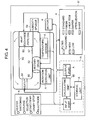
- Fig. 4 is a system block diagram showing a conventional clothes dryer.
- main body 51 of the conventional clothes dryer is provided with, at least, rotary drum 52, heat-exchange type fan 53, heater 54, circulation ducts 55, 56 and 57, calculating unit 58, and humidity sensor 59.
- Rotary drum 52, heat-exchange type fan 53 and heater 54 are connected to a circulation dehumidifying-type clothes dryer through circulation ducts 55, 56 and 57 so as to form air circulation paths thereof.
- heat-exchange type fan 53 air is circulated through circulation ducts 55, 56 and 57 and the inside of rotary drum 52.
- Fig. 5 is a flow chart describing a control method of the control unit in the conventional clothes dryer.
- step S101 After the start of a drying operation, calculating unit 58 first compares a relative humidity level detected by humidity sensor 59 with a first specified value (step S101). When the relative humidity level is less than the first specified value (Yes in step S101), the drying step is completed (step S102), and an air-feeding step is started (step S103). In contrast, the relative humidity level is the first specified value or more (No in step S101), a determination is made as to whether or not any interruption is present (step S106). When any interruption is present (Yes in step S106), the process returns to a main routine, and when no interruption is present (No in step S106), the process returns to step S101 so that the relative humidity level is compared with the first specified value.
- a relative humidity level detected by humidity sensor 59 is compared with a second specified value (step S104).
- a determination is made as to whether or not any interruption is present step S105.
- the process returns to the main routine, and when no interruption is present (No in step S105), the process returns to step S104 so that the relative humidity level is compared with the second specified value.
- the interruption determination is carried out (step S106). In the case where any interruption is present (Yes in step S106), the process returns to the main routine, and when no interruption is present (No in step S106), the process returns to step S101 so that the relative humidity level is compared with the first specified value.
- the clothes dryer of the present invention is provided with: a rotary drum for housing clothes; a motor for driving the rotary drum; an air-feeding unit for feeding drying air into the rotary drum; a heating unit for heating the drying air; an air circulation path having an air supply passage and an air discharge passage for circulating the drying air inside the rotary drum, and; a first humidity sensor for detecting humidity in the drying air that passes through the air supply passage; a second humidity sensor for detecting humidity in the drying air that passes through the air discharge passage; a calculating unit for calculating a change in humidity based on signals from the first humidity sensor and the second humidity sensor; and a control unit for controlling a drying operation, wherein the control unit controls an air-feeding quantity and a temperature of the drying air according to a result of the calculation carried out in the calculating unit.
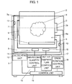
- Fig. 1 is a system block diagram showing a clothes dryer according to a first exemplary embodiment of the present invention.
- main body 1 of the clothes dryer of the present exemplary embodiment is provided with at least rotary drum 2, motor 3, air circulation path 5 having air supply passage 6 and air discharge passage 7, first humidity sensor 10, second humidity sensor 11, calculating unit 12, and control unit 13.
- Rotary drum 2 shaped a substantially cylinder having a bottom is installed in main body 1 of the clothes dryer so as to rotate therein.
- motor 3 attached to the rear surface side of rotary drum 2, rotary drum 2 is driven to rotate around rotation axis 2a that is disposed in a substantially horizontal direction (including a horizontal direction).
- Motor 3 is prepared as, for example, a brushless DC motor whose rotation speed can be freely changed by inverter control, such as PCM (Pulse Code Modulation) and PWM (Pulse Width Modulation).
- Opening 9 is formed on the front side of rotary drum 2, that is, on the side opposite to motor 3, and by opening a freely openable/closeable door (not shown), clothes 4 and the like can be put in or taken out of rotary drum 2.
- a plurality of baffles 8 for stirring clothes 4 and the like are formed on the inner circumferential side face of rotary drum 2, for example.
- Air circulation path 5 for circulating a drying air inside rotary drum 2 is allowed to communicate with rotary drum 2 through air supply port 6a and air discharge port 7a formed in rotary drum 2.
- air supply port 6a communicates with air supply passage 6 formed on the upstream side of air circulation path 5
- discharge port 7a communicates with air discharge passage 7 formed on the downstream side of air circulation path 5.
- first humidity sensor 10 that detects humidity in a drying air that passes through air supply passage 6
- second humidity sensor 11 that detects humidity in a drying air that passes through air discharge passage 7
- control unit 13 controls at least one of air-feeding quantity control unit 15, hot-air temperature control unit 17, and drum rotation control unit 18 so that a drying operation is carried out.
- Air-feeding quantity control unit 15 controls air-feeding unit 14 such as an air-feeding fan, installed in rotary drum 2 so that the air-feeding quantity of drying air to be fed into rotary drum 2 is controlled.
- hot-air temperature control unit 17 controls heating unit 16 such as a heater, installed on the downstream side of air-feeding unit 14, so that the temperature of drying air to be fed into rotary drum 2 is controlled.
- Drum rotation control unit 18 controls motor 3 so as to change the rotation speed of rotary drum 2, switch forward/reversed rotation directions, and control operation time, etc.
- rotary drum 2 rotates at a predetermined rotation speed with motor 3 being controlled by drum rotation control unit 18 of control unit 13. Then, by power-controlling heating unit 16 that is controlled by control unit 13 through hot-air temperature control unit 17, air is heated to a predetermined temperature, and used for drying air. The drying air is directed into rotary drum 2 by air-feeding unit 14 that is controlled by control unit 3 through air-feeding quantity control unit 15.
- Clothes 4 that are loaded into rotary drum 2 are lifted upward by baffles 8 when rotary drum 2 is rotated, and stirred. Thus, clothes 4 and the drying air are made in contact with each other so that moisture of clothes 4 is removed so as to be dried.
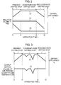
- Fig. 2 is a schematic diagram showing a relationship between the relative humidity and a drying efficiency of clothes relative to operation time of a clothes dryer of the first exemplary embodiment.
- Fig. 2 shows relationships among relative humidity RH1 (20) of air supply passage 6 detected by first humidity sensor 10, relative humidity RH2 (21) of air discharge passage 7 detected by second humidity sensor 11 and a drying efficiency ⁇ (22) of clothes 4 inside rotary drum 2 in a drying step, relative to operation time t in the present first exemplary embodiment.
- the drying efficiency refers to a value obtained by dividing a difference between detection signals inputted from first humidity sensor 10 and second humidity sensor 11 by output setting values of air-feeding quantity and temperature.
- the drying step is transferred from a preheat drying step to a constant-rate drying step and then to a reduced-rate drying step.
- the constant drying step corresponds to a period from completion time t1 of the preheat drying step to completion time t2 of the constant drying step.
- the reduced-rate drying step corresponds to a period from completion time t2 of the constant drying step to completion time t3 of the drying operation. In this case, an accumulated period of time of the preheat drying step, the constant-rate drying step, and the reduced-rate drying step is determined as the drying operation time.
- Calculating unit 12 detects relative humidity RH1 (20) and relative humidity RH2 (21) in the preheat drying step, and when relative humidity RH1 (20) has reached a predetermined value, it detects time t1 at which the preheat drying step has been completed.
- the predetermined value refers to a value at which the value of relative humidity RH1 (20), which has been determined by the output setting value of the air-feeding quantity of air-feeding quantity control unit 15 and the output setting value of the temperature of hot-air temperature control unit 17, becomes constant. Then, based upon detected time t1, completion time t2 of the constant-rate drying step is set.
- time t1 becomes longer since a long period of time is required until relative humidity RH1 (20) has reached the predetermined value.
- time t1 becomes shorter, since so much time is not required until relative humidity RH1 (20) has become the predetermined value. For this reason, since the amount of clothes 4 can be determined based upon the length from the start of an operation to time t1, it is possible to determine whether the period of time of the constant-rate drying step is made longer or shorter.
- calculating unit 12 detects relative humidity RH1 (20) of air supply passage 6 and relative humidity RH2 (21) of air discharge passage 7 in the constant-rate drying step, and in the case where relative humidity RH2 (21) starts becoming smaller than a predetermined value (stable value), detects time t2 at which the constant-rate drying step has been completed.
- a predetermined value stable value
- the predetermined value refers to a value at which the value of relative humidity RH2 (21), which has been determined by the output setting value of the air-feeding quantity of air-feeding quantity control unit 15 and the output setting value of the temperature of hot-air temperature control unit 17, becomes constant.
- time t2 becomes longer.
- time t2 becomes shorter. For this reason, depending on the period of time from time t1 to time t2, it is possible to determine whether the period of time t3 is made longer or shorter.
- Fig. 3 is a schematic diagram showing a relationship between the drying efficiency of clothes relative to operation time of the clothes dryer and output setting values of the air-feeding quantity and the temperature of drying air in the present first exemplary embodiment.
- Fig. 3 schematically shows changes in drying efficiency ⁇ (22) of clothes 4 inside rotary drum 2 in a drying step relative to operation time t, the output setting values 23 of the air-feeding quantity of air-feeding quantity control unit 15 and the temperature of hot-air temperature control unit 17 in the present first exemplary embodiment.
- control unit 13 controls the preheat drying step, with the output setting value of air-feeding quantity control unit 15 and the output setting value of hot-air temperature control unit 17 being set at constant values.
- drying efficiency ⁇ (22) is kept constant; however, in the case of entanglement of clothes 4 in the middle of the operation, drying efficiency ⁇ (22) is lowered.
- control unit 13 detects the degree of entanglement of clothes 4. Then, according to the degree of entanglement of clothes 4 thus detected, drum rotation control unit 18 changes settings of the rotation speed of rotary drum 2 and the rotation direction.
- drying efficiency ⁇ (22) in order to quickly return reduced drying efficiency ⁇ (22) to the value of drying efficiency ⁇ (22) prior to the reduction, it allows rotary drum 2 to rotate at high speeds as well as at low speeds, or controls rotary drum 2 so as to forwardly and reversely rotate for predetermined periods of time.
- the entanglement of clothes 4 is lessened so as to dry clothes 4 so that drying efficiency ⁇ (22) is improved.
- control unit 13 upon detection of entanglement of clothes 4, control unit 13 reduces the output setting value of the air-feeding quantity of air-feeding quantity control unit 15 and the output setting value of the temperature of hot-air temperature control unit 17 according to the degree of entanglement of clothes 4. More specifically, upon detection of the degree of entanglement of clothes 4, control unit 13 controls hot-air temperature control unit 17 to reduce the temperature of the drying air. When the entanglement of clothes 4 is lessened, it increases the output setting value of the temperature of hot-air temperature control unit 17, and returns the value to its original output setting value. In the same manner, upon detection of the degree of entanglement of clothes 4, control unit 13 controls air-feeding quantity control unit 15 to reduce the air-feeding quantity of drying air.
- control unit 13 carries out controlling, with the output setting value of the air-feeding quantity of air-feeding quantity control unit 15 and the output setting value of the temperature of hot-air temperature control unit 17 being kept constant, energy that does not devote to evaporation becomes greater; that is, when control unit 13 carries out controlling, with the output setting value of the air-feeding quantity of air-feeding quantity control unit 15 and the output setting value of the temperature of hot-air temperature control unit 17 being kept constant, a wasteful energy consumption occurs. Therefore, as shown in Fig.
- the output setting value of the air-feeding quantity of air-feeding quantity control unit 15 and the output setting value of the temperature of hot-air temperature control unit 17 are lowered so that the energy required for generating hot air to be fed into rotary drum 2 is reduced.
- the output setting value of the air-feeding quantity of air-feeding quantity control unit 15 and the output setting value of the temperature of hot-air temperature control unit 17 are returned to the original values so that the energy required for generating hot air to be fed into rotary drum 2 is increased.
- control unit 13 carries out controlling, with the output setting value of air-feeding quantity control unit 15 and the output setting value of hot-air temperature control unit 17 being kept constant values.
- drying efficiency ⁇ (22) of clothes 4 inside rotary drum 2 is lowered from completion time t2 of the constant-rate drying step to completion time t3 of the reduced-rate drying step.
- the present embodiment has been explained by exemplifying a structure in which, according to the degree of entanglement of clothes 4, the output setting value of air-feeding quantity control unit 15 and the output setting value of hot-air temperature control unit 17 are changed; however, the present invention is not intended to be limited by this structure.
- the controlling may be carried out by changing either one of the output setting value of air-feeding quantity control unit 15 and the output setting value of hot-air temperature control unit 17.
- hot-air temperature control unit 17 controls heating unit 16 such as a heater; however, the present invention is not intended to be limited by this structure.
- it may control a heat pump or the like using an inverter-controlled compressor with its rotation speed being variably changed. With this arrangement, it is possible to achieve a clothes dryer having a superior energy saving performance.
Landscapes
- Engineering & Computer Science (AREA)
- Textile Engineering (AREA)
- Control Of Washing Machine And Dryer (AREA)
Abstract
Description
- The present invention relates to a clothes dryer for drying clothes and the like in a rotary drum.
- In recent years, there have been strong demands for a clothes dryer having superior energy-saving performances, which detects a drying efficiency of clothes in a rotary drum during a drying operation with high precision, and carries out an optimal drying operation.
- For example, Unexamined Japanese Patent Publication No.
H09-285696 - Referring to
Fig. 4 , the following description will discuss the clothes dryer disclosed in thePatent Document 1. -
Fig. 4 is a system block diagram showing a conventional clothes dryer. - As shown in
Fig. 4 ,main body 51 of the conventional clothes dryer is provided with, at least,rotary drum 52, heat-exchange type fan 53,heater 54,circulation ducts unit 58, andhumidity sensor 59. Rotarydrum 52, heat-exchange type fan 53 andheater 54 are connected to a circulation dehumidifying-type clothes dryer throughcirculation ducts exchange type fan 53, air is circulated throughcirculation ducts rotary drum 52. - Referring to
Fig. 4 , the following description will discuss controlling operations of a control unit of the conventional clothes dryer having the above-mentioned structure with reference toFig. 5 . -
Fig. 5 is a flow chart describing a control method of the control unit in the conventional clothes dryer. - As shown in
Fig. 5 , after the start of a drying operation, calculatingunit 58 first compares a relative humidity level detected byhumidity sensor 59 with a first specified value (step S101). When the relative humidity level is less than the first specified value (Yes in step S101), the drying step is completed (step S102), and an air-feeding step is started (step S103). In contrast, the relative humidity level is the first specified value or more (No in step S101), a determination is made as to whether or not any interruption is present (step S106). When any interruption is present (Yes in step S106), the process returns to a main routine, and when no interruption is present (No in step S106), the process returns to step S101 so that the relative humidity level is compared with the first specified value. - Next, after the start of the air-feeding step, a relative humidity level detected by
humidity sensor 59 is compared with a second specified value (step S104). When the relative humidity level is less than the second specified value (Yes in step S104), a determination is made as to whether or not any interruption is present (step S105). In the case where any interruption is present (Yes in step S105), the process returns to the main routine, and when no interruption is present (No in step S105), the process returns to step S104 so that the relative humidity level is compared with the second specified value. On the other hand, in the case where the relative humidity level is the second specified value or more (No in step S104), the interruption determination is carried out (step S106). In the case where any interruption is present (Yes in step S106), the process returns to the main routine, and when no interruption is present (No in step S106), the process returns to step S101 so that the relative humidity level is compared with the first specified value. - In other words, in the air-feeding step after the completion of the drying step, humidity of air discharged from
rotary drum 52 is again detected so that the dried state is detected. Thus, when there are any irregularities in the dried state of articles to be dried, the drying step is again carried out so as to reduce the occurrence of irregularities in the dried state. - In the conventional clothes dryer, however, power supply to
heater 54 is stopped after the completion of the drying step. Then, in the case where there are any irregularities in the dried state of articles to be dried in the air-feeding step, the process again returns to the drying step to again start the power supply toheater 54. Consequently, the frequency to supply power toheater 54 becomes high, thereby increasing energy consumption. - The clothes dryer of the present invention is provided with: a rotary drum for housing clothes; a motor for driving the rotary drum; an air-feeding unit for feeding drying air into the rotary drum; a heating unit for heating the drying air; an air circulation path having an air supply passage and an air discharge passage for circulating the drying air inside the rotary drum, and; a first humidity sensor for detecting humidity in the drying air that passes through the air supply passage; a second humidity sensor for detecting humidity in the drying air that passes through the air discharge passage; a calculating unit for calculating a change in humidity based on signals from the first humidity sensor and the second humidity sensor; and a control unit for controlling a drying operation, wherein the control unit controls an air-feeding quantity and a temperature of the drying air according to a result of the calculation carried out in the calculating unit. With this structure, it becomes possible to carry out an optimal drying operation without any irregularities in the dried state of clothes, which is superior in energy-saving performances.
-
-
Fig. 1 shows a system block diagram showing a clothes dryer according to a first exemplary embodiment of the present invention; -
Fig. 2 shows a schematic diagram showing a relationship between the relative humidity and drying efficiency of clothes relative to operation time of the clothes dryer; -
Fig. 3 shows a schematic diagram showing a relationship between the drying efficiency of clothes relative to operation time of the clothes dryer and output setting values of air-feeding quantity and temperature of drying air; -
Fig. 4 shows a system block diagram showing a conventional clothes dryer; and -
Fig. 5 shows a flow chart describing a control method of a control unit of the clothes dryer. - The following description will discuss exemplary embodiments of the present invention with reference to the drawings. The present invention is not intended to be limited by these exemplary embodiments.
-
Fig. 1 is a system block diagram showing a clothes dryer according to a first exemplary embodiment of the present invention. As shown inFig. 1 ,main body 1 of the clothes dryer of the present exemplary embodiment is provided with at leastrotary drum 2, motor 3,air circulation path 5 havingair supply passage 6 andair discharge passage 7,first humidity sensor 10,second humidity sensor 11, calculatingunit 12, andcontrol unit 13. -
Rotary drum 2 shaped a substantially cylinder having a bottom (including a cylinder having a bottom), is installed inmain body 1 of the clothes dryer so as to rotate therein. By motor 3 attached to the rear surface side ofrotary drum 2,rotary drum 2 is driven to rotate aroundrotation axis 2a that is disposed in a substantially horizontal direction (including a horizontal direction). Motor 3 is prepared as, for example, a brushless DC motor whose rotation speed can be freely changed by inverter control, such as PCM (Pulse Code Modulation) and PWM (Pulse Width Modulation). -
Opening 9 is formed on the front side ofrotary drum 2, that is, on the side opposite to motor 3, and by opening a freely openable/closeable door (not shown),clothes 4 and the like can be put in or taken out ofrotary drum 2. On the inner circumferential side face ofrotary drum 2, for example, a plurality ofbaffles 8 for stirringclothes 4 and the like are formed. Thus,clothes 4 and the like housed insiderotary drum 2 are lifted bybaffles 8 formed inrotary drum 2, and stirred insiderotary drum 2 by the rotation ofrotary drum 2. -
Air circulation path 5 for circulating a drying air insiderotary drum 2, is allowed to communicate withrotary drum 2 throughair supply port 6a andair discharge port 7a formed inrotary drum 2. At this time,air supply port 6a communicates withair supply passage 6 formed on the upstream side ofair circulation path 5, anddischarge port 7a communicates withair discharge passage 7 formed on the downstream side ofair circulation path 5. - Moreover,
first humidity sensor 10 that detects humidity in a drying air that passes throughair supply passage 6 andsecond humidity sensor 11 that detects humidity in a drying air that passes throughair discharge passage 7 are installed inair circulation path 5. At this time,first humidity sensor 10 andsecond humidity sensor 11 are connected to calculatingunit 12, and calculatingunit 12 is connected tocontrol unit 13. That is,first humidity sensor 10 andsecond humidity sensor 11 respectively detect the relative humidity in drying steps ofair supply passage 6 andair discharge passage 7, and output the detection results to calculatingunit 12. Thereafter, the results of calculations carried out in calculatingunit 12 are outputted to controlunit 13. According to the inputted calculation results,control unit 13 controls at least one of air-feedingquantity control unit 15, hot-airtemperature control unit 17, and drumrotation control unit 18 so that a drying operation is carried out. - Air-feeding
quantity control unit 15 controls air-feeding unit 14 such as an air-feeding fan, installed inrotary drum 2 so that the air-feeding quantity of drying air to be fed intorotary drum 2 is controlled. - Moreover, hot-air
temperature control unit 17 controlsheating unit 16 such as a heater, installed on the downstream side of air-feeding unit 14, so that the temperature of drying air to be fed intorotary drum 2 is controlled. - Drum
rotation control unit 18 controls motor 3 so as to change the rotation speed ofrotary drum 2, switch forward/reversed rotation directions, and control operation time, etc. - The following description will discuss operations and functions of the clothes dryer having the above-mentioned structure.
- First, upon starting a drying operation,
rotary drum 2 rotates at a predetermined rotation speed with motor 3 being controlled by drumrotation control unit 18 ofcontrol unit 13. Then, by power-controllingheating unit 16 that is controlled bycontrol unit 13 through hot-airtemperature control unit 17, air is heated to a predetermined temperature, and used for drying air. The drying air is directed intorotary drum 2 by air-feeding unit 14 that is controlled by control unit 3 through air-feedingquantity control unit 15. -
Clothes 4 that are loaded intorotary drum 2 are lifted upward bybaffles 8 whenrotary drum 2 is rotated, and stirred. Thus,clothes 4 and the drying air are made in contact with each other so that moisture ofclothes 4 is removed so as to be dried. - Referring to
Figs .2 and 3 , the following description will discuss a specific control method for a clothes dryer. -
Fig. 2 is a schematic diagram showing a relationship between the relative humidity and a drying efficiency of clothes relative to operation time of a clothes dryer of the first exemplary embodiment. In other words,Fig. 2 shows relationships among relative humidity RH1 (20) ofair supply passage 6 detected byfirst humidity sensor 10, relative humidity RH2 (21) ofair discharge passage 7 detected bysecond humidity sensor 11 and a drying efficiency η (22) ofclothes 4 insiderotary drum 2 in a drying step, relative to operation time t in the present first exemplary embodiment. Additionally, the drying efficiency refers to a value obtained by dividing a difference between detection signals inputted fromfirst humidity sensor 10 andsecond humidity sensor 11 by output setting values of air-feeding quantity and temperature. - As shown in
Fig. 2 , the drying step is transferred from a preheat drying step to a constant-rate drying step and then to a reduced-rate drying step. The preheat drying step corresponds to a period from operation start time t = 0 to completion time t1 of the preheat drying step. The constant drying step corresponds to a period from completion time t1 of the preheat drying step to completion time t2 of the constant drying step. The reduced-rate drying step corresponds to a period from completion time t2 of the constant drying step to completion time t3 of the drying operation. In this case, an accumulated period of time of the preheat drying step, the constant-rate drying step, and the reduced-rate drying step is determined as the drying operation time. - Calculating
unit 12 detects relative humidity RH1 (20) and relative humidity RH2 (21) in the preheat drying step, and when relative humidity RH1 (20) has reached a predetermined value, it detects time t1 at which the preheat drying step has been completed. In this case, the predetermined value refers to a value at which the value of relative humidity RH1 (20), which has been determined by the output setting value of the air-feeding quantity of air-feedingquantity control unit 15 and the output setting value of the temperature of hot-airtemperature control unit 17, becomes constant. Then, based upon detected time t1, completion time t2 of the constant-rate drying step is set. - In the case where the amount of clothes is large, time t1 becomes longer since a long period of time is required until relative humidity RH1 (20) has reached the predetermined value. On the other hand, in the case where the amount of clothes is small, time t1 becomes shorter, since so much time is not required until relative humidity RH1 (20) has become the predetermined value. For this reason, since the amount of
clothes 4 can be determined based upon the length from the start of an operation to time t1, it is possible to determine whether the period of time of the constant-rate drying step is made longer or shorter. - Moreover, in the case where
clothes 4 are in a more moistened state, since a long period of time is required until relative humidity RH1 (20) has reached the predetermined value, time t1 becomes longer. In contrast, in the case whereclothes 4 are in a more dried state, since so much time is not required until relative humidity RH1 (20) has reached the predetermined value, time t1 becomes shorter. For this reason, since the state ofclothes 4 can be determined depending on the period of time from the start of the operation to time t1, it is possible to determine whether the period of time of the constant-rate drying step is made longer or shorter. Thus, according to the amount and state ofclothes 4, operation time of the constant-rate drying step can be optimized. - Next, calculating
unit 12 detects relative humidity RH1 (20) ofair supply passage 6 and relative humidity RH2 (21) ofair discharge passage 7 in the constant-rate drying step, and in the case where relative humidity RH2 (21) starts becoming smaller than a predetermined value (stable value), detects time t2 at which the constant-rate drying step has been completed. The reason for this is because, since the surface ofclothes 4 is moistened state up to the constant-rate drying step, hot air for dryingclothes 4 evaporates moisture on the surface ofclothes 4 so that, since warm air containing a fixed amount of moisture is discharged, relative humidity RH2 (21) becomes constant. In contrast, in the reduced-rate drying step, as the surface ofclothes 4 is dried up, moisture to be evaporated from the surface ofclothes 4 becomes smaller by hot air used for dryingclothes 4; therefore, relative humidity RH2 (21) becomes smaller. For this reason, based upon completion time t2 of the constant-rate drying step, completion time t3 for the drying operation is set. In this case, the predetermined value refers to a value at which the value of relative humidity RH2 (21), which has been determined by the output setting value of the air-feeding quantity of air-feedingquantity control unit 15 and the output setting value of the temperature of hot-airtemperature control unit 17, becomes constant. - In the case where the amount of clothes is large, since a long period of time is required until relative humidity RH2 (21) has become smaller than the predetermined value, time t2 becomes longer. In contrast, in the case where the amount of clothes is small, since so much time is not required until relative humidity RH2 (21) has become smaller than the predetermined value (stable value), time t2 becomes shorter. For this reason, depending on the period of time from time t1 to time t2, it is possible to determine whether the period of time t3 is made longer or shorter.
- Furthermore, in the case where
clothes 4 are in a more moistened state, since more time is required until relative humidity RH2 (21) has become smaller than the predetermined value (stable value), time t2 becomes longer. In contrast, in the case whereclothes 4 are in a more dried state, since so much time is not required until it has become smaller than the predetermined value (stable value), time t2 becomes shorter. For this reason, depending on the period of time from time t1 to time t2, it is possible to determine whether the period of time t3 is made longer or shorter. Thus, since the completion time of the drying operation is set depending on the amount and state ofclothes 4, it becomes possible to complete the drying operation at optimal time. -
Fig. 3 is a schematic diagram showing a relationship between the drying efficiency of clothes relative to operation time of the clothes dryer and output setting values of the air-feeding quantity and the temperature of drying air in the present first exemplary embodiment.Fig. 3 schematically shows changes in drying efficiency η (22) ofclothes 4 insiderotary drum 2 in a drying step relative to operation time t, the output setting values 23 of the air-feeding quantity of air-feedingquantity control unit 15 and the temperature of hot-airtemperature control unit 17 in the present first exemplary embodiment. - As shown in
Fig. 3 , after the start of a drying operation,control unit 13 controls the preheat drying step, with the output setting value of air-feedingquantity control unit 15 and the output setting value of hot-airtemperature control unit 17 being set at constant values. At this time, drying efficiency η (22) ofclothes 4 insiderotary drum 2 rises from operation start time t = 0 to completion time t1 of the preheat drying step, in the same manner as inFig. 2 . - Next, in the constant-rate drying step, the drying operation proceeds, with drying efficiency η (22) being kept constant; however, in the case of entanglement of
clothes 4 in the middle of the operation, drying efficiency η (22) is lowered. In the case of reduced drying efficiency η (22) ofclothes 4 insiderotary drum 2,control unit 13 detects the degree of entanglement ofclothes 4. Then, according to the degree of entanglement ofclothes 4 thus detected, drumrotation control unit 18 changes settings of the rotation speed ofrotary drum 2 and the rotation direction. For example, in order to quickly return reduced drying efficiency η (22) to the value of drying efficiency η (22) prior to the reduction, it allowsrotary drum 2 to rotate at high speeds as well as at low speeds, or controlsrotary drum 2 so as to forwardly and reversely rotate for predetermined periods of time. Thus, the entanglement ofclothes 4 is lessened so as todry clothes 4 so that drying efficiency η (22) is improved. - At this time, upon detection of entanglement of
clothes 4,control unit 13 reduces the output setting value of the air-feeding quantity of air-feedingquantity control unit 15 and the output setting value of the temperature of hot-airtemperature control unit 17 according to the degree of entanglement ofclothes 4. More specifically, upon detection of the degree of entanglement ofclothes 4,control unit 13 controls hot-airtemperature control unit 17 to reduce the temperature of the drying air. When the entanglement ofclothes 4 is lessened, it increases the output setting value of the temperature of hot-airtemperature control unit 17, and returns the value to its original output setting value. In the same manner, upon detection of the degree of entanglement ofclothes 4,control unit 13 controls air-feedingquantity control unit 15 to reduce the air-feeding quantity of drying air. When the entanglement ofclothes 4 is lessened, it increases the output setting value of the air-feeding quantity of air-feedingquantity control unit 15, and returns the value to its original output setting value. That is, in the case of reduction of drying efficiency η (22) ofclothes 4 insiderotary drum 2, the output setting values of the air-feeding quantity and the temperature of drying air are lowered. In contrast, when drying efficiency η (22) ofclothes 4 insiderotary drum 2 is turned to rise, it returns the output setting values of the air-feeding quantity and the temperature of drying air to the original output setting values. - The following description will discuss why the output setting values of the air-feeding quantity and the temperature of drying air are lowered based upon the reduction of drying efficiency η (22) so as to carry out controlling.
- In the case of the entanglement of
clothes 4, since the surface area ofclothes 4 that is made in contact with hot air for dryingclothes 4 is narrowed, moisture is hardly evaporated from the surface ofclothes 4. For this reason, in the case wherecontrol unit 13 carries out controlling, with the output setting value of the air-feeding quantity of air-feedingquantity control unit 15 and the output setting value of the temperature of hot-airtemperature control unit 17 being kept constant, energy that does not devote to evaporation becomes greater; that is, whencontrol unit 13 carries out controlling, with the output setting value of the air-feeding quantity of air-feedingquantity control unit 15 and the output setting value of the temperature of hot-airtemperature control unit 17 being kept constant, a wasteful energy consumption occurs. Therefore, as shown inFig. 3 , the output setting value of the air-feeding quantity of air-feedingquantity control unit 15 and the output setting value of the temperature of hot-airtemperature control unit 17 are lowered so that the energy required for generating hot air to be fed intorotary drum 2 is reduced. On the other hand, in the case where the entanglement ofclothes 4 is lessened, since the surface area ofclothes 4 that is made in contact with hot air for dryingclothes 4 is widened, moisture is more easily evaporated from the surface ofclothes 4. Therefore, the output setting value of the air-feeding quantity of air-feedingquantity control unit 15 and the output setting value of the temperature of hot-airtemperature control unit 17 are returned to the original values so that the energy required for generating hot air to be fed intorotary drum 2 is increased. With this arrangement, by optimally setting the air-feeding quantity and the temperature of drying air in response to the change in the drying efficiency ofclothes 4 insiderotary drum 2, it is possible to achieve a drying operation in which more energy is saved. - Next, in a reduced-rate drying step after the completion of the constant-rate drying step,
control unit 13 carries out controlling, with the output setting value of air-feedingquantity control unit 15 and the output setting value of hot-airtemperature control unit 17 being kept constant values. Thus, drying efficiency η (22) ofclothes 4 insiderotary drum 2 is lowered from completion time t2 of the constant-rate drying step to completion time t3 of the reduced-rate drying step. - Additionally, the present embodiment has been explained by exemplifying a structure in which, according to the degree of entanglement of
clothes 4, the output setting value of air-feedingquantity control unit 15 and the output setting value of hot-airtemperature control unit 17 are changed; however, the present invention is not intended to be limited by this structure. For example, the controlling may be carried out by changing either one of the output setting value of air-feedingquantity control unit 15 and the output setting value of hot-airtemperature control unit 17. With this arrangement, by optimally setting the air-feeding quantity or the temperature of drying air according to the change in the drying efficiency ofclothes 4 insiderotary drum 2, it is possible to achieve a drying operation in which more energy is saved. - Moreover, the present embodiment has been explained by exemplifying a structure in which hot-air
temperature control unit 17controls heating unit 16 such as a heater; however, the present invention is not intended to be limited by this structure. For example, it may control a heat pump or the like using an inverter-controlled compressor with its rotation speed being variably changed. With this arrangement, it is possible to achieve a clothes dryer having a superior energy saving performance.
Claims (7)
- A clothes dryer comprising:a rotary drum for housing clothes;a motor for driving the rotary drum;an air-feeding unit for feeding drying air into the rotary drum;a heating unit for heating the drying air;an air circulation path having an air supply passage and an air discharge passage for circulating the drying air inside the rotary drum, and;a first humidity sensor for detecting humidity in the drying air that passes through the air supply passage;a second humidity sensor for detecting humidity in the drying air that passes through the air discharge passage;a calculating unit for calculating a change in humidity based on signals from the first humidity sensor and the second humidity sensor; anda control unit for controlling a drying operation, whereinthe control unit controls an air-feeding quantity and a temperature of the drying air according to a result of the calculation carried out in the calculating unit.
- The clothes dryer according to claim 1, wherein
the calculating unit calculates signals from the first humidity sensor and the second humidity sensor during a preheat drying step, and sets a completion time of a constant-rate drying step. - The clothes dryer according to claim 1, wherein
the calculating unit calculates signals from the first humidity sensor and the second humidity sensor during a constant-rate drying step, and sets a drying operation completion time. - The clothes dryer according to claim 1, wherein
the control unit detects a degree of entanglement of clothes in a constant-rate drying step according to a the result of calculation carried out in the calculating unit. - The clothes dryer according to claim 4, wherein
the control unit controls a temperature of the drying air according to the degree of entanglement of clothes. - The clothes dryer according to claim 4, wherein
the control unit controls an air-feeding quantity of the drying air according to the degree of entanglement of clothes. - The clothes dryer according to any one of claims 4 to 6, wherein
the control unit further controls rotation of the rotary drum according to the degree of entanglement of clothes.
Applications Claiming Priority (1)
| Application Number | Priority Date | Filing Date | Title |
|---|---|---|---|
| JP2010199613A JP2012055400A (en) | 2010-09-07 | 2010-09-07 | Clothes dryer |
Publications (1)
| Publication Number | Publication Date |
|---|---|
| EP2436833A1 true EP2436833A1 (en) | 2012-04-04 |
Family
ID=44735830
Family Applications (1)
| Application Number | Title | Priority Date | Filing Date |
|---|---|---|---|
| EP11178702A Withdrawn EP2436833A1 (en) | 2010-09-07 | 2011-08-24 | Clothes dryer |
Country Status (3)
| Country | Link |
|---|---|
| EP (1) | EP2436833A1 (en) |
| JP (1) | JP2012055400A (en) |
| CN (1) | CN102433722B (en) |
Cited By (6)
| Publication number | Priority date | Publication date | Assignee | Title |
|---|---|---|---|---|
| DE102013215675A1 (en) * | 2013-08-08 | 2015-02-12 | BSH Bosch und Siemens Hausgeräte GmbH | Operating a laundry dryer with horizontally rotatable laundry drum |
| WO2015127995A1 (en) * | 2014-02-28 | 2015-09-03 | Arcelik Anonim Sirketi | Laundry dryer with a cloth disentangling mode and method for controlling the same |
| WO2016015765A1 (en) * | 2014-07-31 | 2016-02-04 | Electrolux Appliances Aktiebolag | Laundry treatment apparatus with humidity detector |
| EP3031978A1 (en) * | 2014-12-09 | 2016-06-15 | LG Electronics Inc. | Dryer and control method thereof |
| KR20160070042A (en) * | 2016-04-27 | 2016-06-17 | 엘지전자 주식회사 | Dryer and control method for dryer |
| US9371609B2 (en) | 2014-06-24 | 2016-06-21 | General Electric Company | Dryer appliances and methods for operating same |
Families Citing this family (13)
| Publication number | Priority date | Publication date | Assignee | Title |
|---|---|---|---|---|
| JP6716213B2 (en) * | 2015-07-15 | 2020-07-01 | 東芝ライフスタイル株式会社 | Dryer |
| KR101613963B1 (en) | 2014-12-08 | 2016-04-20 | 엘지전자 주식회사 | Clothes treating apparatus with a heat pump system |
| KR101613965B1 (en) | 2014-12-08 | 2016-04-20 | 엘지전자 주식회사 | Control method for exhaust-type dryer |
| DE102016108863A1 (en) * | 2016-05-13 | 2017-11-16 | TRüTZSCHLER GMBH & CO. KG | Dryer for a textile web with a device for energy minimized operation and method for this purpose |
| CN106839200A (en) * | 2017-01-06 | 2017-06-13 | 青岛海尔空调器有限总公司 | A kind of air-conditioner and its control method with drying component |
| CN109402985B (en) * | 2017-08-18 | 2022-05-27 | 青岛海尔滚筒洗衣机有限公司 | Clothes treatment device and clothes treatment method |
| JP7082532B2 (en) * | 2018-06-20 | 2022-06-08 | 東芝ライフスタイル株式会社 | Clothes dryer and washer / dryer |
| CN110042637A (en) * | 2019-04-08 | 2019-07-23 | 青岛海尔滚筒洗衣机有限公司 | A kind of the winding detection method and clothing drying device of clothing drying device |
| KR102834308B1 (en) * | 2020-06-24 | 2025-07-17 | 엘지전자 주식회사 | Control method of laundry treating apparatus |
| WO2021261918A1 (en) | 2020-06-24 | 2021-12-30 | Lg Electronics Inc. | Method for controlling laundry treating apparatus |
| CN115917072A (en) | 2020-06-24 | 2023-04-04 | Lg电子株式会社 | Clothes processing equipment |
| KR102866173B1 (en) * | 2021-04-19 | 2025-10-01 | 엘지전자 주식회사 | A laundry treating apparatus |
| KR102758942B1 (en) * | 2021-04-19 | 2025-01-24 | 엘지전자 주식회사 | A laundry treating apparatus |
Citations (4)
| Publication number | Priority date | Publication date | Assignee | Title |
|---|---|---|---|---|
| EP0388939A1 (en) * | 1989-03-24 | 1990-09-26 | Sanyo Electric Co., Ltd. | Device and method for controlling operation of clothes dryer |
| JPH09285696A (en) | 1996-04-22 | 1997-11-04 | Matsushita Electric Ind Co Ltd | Clothes dryer |
| US20100037480A1 (en) * | 2007-04-20 | 2010-02-18 | Bsh Bosch Und Siemens Hausgerate Gmbh | Method for operating a condenser tumble-dryer comprising a thermal pump and a condenser tumble dryer that is suitable for said method |
| EP2343412A1 (en) * | 2010-01-06 | 2011-07-13 | Samsung Electronics Co., Ltd. | Clothing dryer and control method thereof |
Family Cites Families (1)
| Publication number | Priority date | Publication date | Assignee | Title |
|---|---|---|---|---|
| CN100503939C (en) * | 2004-09-06 | 2009-06-24 | 乐金电子(天津)电器有限公司 | Automatic drying device and method for drum washing machine |
-
2010
- 2010-09-07 JP JP2010199613A patent/JP2012055400A/en active Pending
-
2011
- 2011-08-24 EP EP11178702A patent/EP2436833A1/en not_active Withdrawn
- 2011-09-07 CN CN2011102688794A patent/CN102433722B/en not_active Expired - Fee Related
Patent Citations (4)
| Publication number | Priority date | Publication date | Assignee | Title |
|---|---|---|---|---|
| EP0388939A1 (en) * | 1989-03-24 | 1990-09-26 | Sanyo Electric Co., Ltd. | Device and method for controlling operation of clothes dryer |
| JPH09285696A (en) | 1996-04-22 | 1997-11-04 | Matsushita Electric Ind Co Ltd | Clothes dryer |
| US20100037480A1 (en) * | 2007-04-20 | 2010-02-18 | Bsh Bosch Und Siemens Hausgerate Gmbh | Method for operating a condenser tumble-dryer comprising a thermal pump and a condenser tumble dryer that is suitable for said method |
| EP2343412A1 (en) * | 2010-01-06 | 2011-07-13 | Samsung Electronics Co., Ltd. | Clothing dryer and control method thereof |
Cited By (7)
| Publication number | Priority date | Publication date | Assignee | Title |
|---|---|---|---|---|
| DE102013215675A1 (en) * | 2013-08-08 | 2015-02-12 | BSH Bosch und Siemens Hausgeräte GmbH | Operating a laundry dryer with horizontally rotatable laundry drum |
| WO2015127995A1 (en) * | 2014-02-28 | 2015-09-03 | Arcelik Anonim Sirketi | Laundry dryer with a cloth disentangling mode and method for controlling the same |
| US9371609B2 (en) | 2014-06-24 | 2016-06-21 | General Electric Company | Dryer appliances and methods for operating same |
| WO2016015765A1 (en) * | 2014-07-31 | 2016-02-04 | Electrolux Appliances Aktiebolag | Laundry treatment apparatus with humidity detector |
| EP3031978A1 (en) * | 2014-12-09 | 2016-06-15 | LG Electronics Inc. | Dryer and control method thereof |
| US10301765B2 (en) | 2014-12-09 | 2019-05-28 | Lg Electronics Inc. | Dryer and control method thereof |
| KR20160070042A (en) * | 2016-04-27 | 2016-06-17 | 엘지전자 주식회사 | Dryer and control method for dryer |
Also Published As
| Publication number | Publication date |
|---|---|
| CN102433722A (en) | 2012-05-02 |
| CN102433722B (en) | 2013-09-11 |
| JP2012055400A (en) | 2012-03-22 |
Similar Documents
| Publication | Publication Date | Title |
|---|---|---|
| EP2436833A1 (en) | Clothes dryer | |
| EP2343412B1 (en) | Clothing dryer and control method thereof | |
| EP1408151B1 (en) | Condensation clothes dryer and method for controlling operation thereof | |
| EP1688532B1 (en) | Automatic clothes dryer | |
| US7171763B2 (en) | Dryer control method and dryer using the same | |
| KR102459154B1 (en) | Dryer and method for controlling the same | |
| EP1508637A2 (en) | Method for controlling clothes dryer | |
| US7644513B2 (en) | Laundry dryer and method for controlling drying course of the same | |
| GB2279448A (en) | Tumble dryer control | |
| US20090049709A1 (en) | Dryer and Dry Method for the Same | |
| JP2013128632A (en) | Clothing drying machine | |
| US20050132599A1 (en) | Drying method of washing machine and apparatus thereof | |
| KR20200105026A (en) | Dryer and method for controlling the same | |
| JP5647797B2 (en) | Drying operation control method for bathroom heating dryer | |
| KR0141778B1 (en) | Dehumidifying clothes dryer with air volume control | |
| JP2003144791A (en) | Washing and drying machine | |
| JP7000042B2 (en) | Bathroom heater / dryer | |
| JP2002233695A (en) | Clothes dryer | |
| JP4460326B2 (en) | Control method of laundry dryer | |
| JP2005130892A (en) | Clothes drying apparatus and washing machine with drying function provided with the apparatus | |
| JPH0759276B2 (en) | Dryer | |
| JP2598800B2 (en) | Clothes dryer | |
| JP2011104144A (en) | Clothes dryer | |
| JP2005137505A (en) | Clothes dryer | |
| JP2000061196A (en) | Dehumidifying clothes dryer |
Legal Events
| Date | Code | Title | Description |
|---|---|---|---|
| PUAI | Public reference made under article 153(3) epc to a published international application that has entered the european phase |
Free format text: ORIGINAL CODE: 0009012 |
|
| AK | Designated contracting states |
Kind code of ref document: A1 Designated state(s): AL AT BE BG CH CY CZ DE DK EE ES FI FR GB GR HR HU IE IS IT LI LT LU LV MC MK MT NL NO PL PT RO RS SE SI SK SM TR |
|
| AX | Request for extension of the european patent |
Extension state: BA ME |
|
| 17P | Request for examination filed |
Effective date: 20120925 |
|
| GRAP | Despatch of communication of intention to grant a patent |
Free format text: ORIGINAL CODE: EPIDOSNIGR1 |
|
| INTG | Intention to grant announced |
Effective date: 20160302 |
|
| STAA | Information on the status of an ep patent application or granted ep patent |
Free format text: STATUS: THE APPLICATION IS DEEMED TO BE WITHDRAWN |
|
| 18D | Application deemed to be withdrawn |
Effective date: 20160713 |