EP2436831A1 - Laundry drying processor - Google Patents
Laundry drying processor Download PDFInfo
- Publication number
- EP2436831A1 EP2436831A1 EP11182087A EP11182087A EP2436831A1 EP 2436831 A1 EP2436831 A1 EP 2436831A1 EP 11182087 A EP11182087 A EP 11182087A EP 11182087 A EP11182087 A EP 11182087A EP 2436831 A1 EP2436831 A1 EP 2436831A1
- Authority
- EP
- European Patent Office
- Prior art keywords
- rotating shaft
- dry air
- housing
- plug
- power
- Prior art date
- Legal status (The legal status is an assumption and is not a legal conclusion. Google has not performed a legal analysis and makes no representation as to the accuracy of the status listed.)
- Granted
Links
Images





Classifications
-
- D—TEXTILES; PAPER
- D06—TREATMENT OF TEXTILES OR THE LIKE; LAUNDERING; FLEXIBLE MATERIALS NOT OTHERWISE PROVIDED FOR
- D06F—LAUNDERING, DRYING, IRONING, PRESSING OR FOLDING TEXTILE ARTICLES
- D06F58/00—Domestic laundry dryers
- D06F58/20—General details of domestic laundry dryers
- D06F58/22—Lint collecting arrangements
Definitions
- the present invention is related to a laundry drying processor for drying laundry.
- a laundry drying processor such as a laundry dryer for drying laundry or a washing and drying machine with drying functions and washing functions, typically supplies dry air into its drum in which laundry is stored, to dry the laundry.
- Japanese Patent Application Publication No. 2007-82586 discloses a laundry drying processor which includes an external air introduction system configured to improve drying efficiency of the laundry drying processor.
- the laundry drying processor includes a housing and a heat pump configured to dehumidify and heat air inside the housing to produce dry air.
- the laundry drying processor takes external air into the housing to cool the heat pump as appropriate, which results in more efficient heat exchange of the heat pump.
- a typical laundry drying processor has a filter configured to remove lint (dust such as yam wastes), which is separated from laundry during a drying process. The filter clogged with the lint decreases the amount of the dry air.
- a general laundry drying processor has a blower configured to circulate the dry air inside the housing.
- the blower is controlled to keep an amount of the dry air flowing inside the housing at a predetermined level. If the filter becomes clogged with the lint as described above, the blower rotates a fan thereof at a relatively high rotating speed, which moderates a decrease in flow rate of the dry air caused by the lint. On the other hand, a high speed rotation of the fan results in more power consumption by the blower.
- An object of the present invention is to provide a laundry drying processor to achieve power saving.
- a laundry drying processor has: a drying tub including an intake port into which dry air for drying laundry flows and an exhaust port from which the dry air is exhausted; a removal device configured to remove lint from the dry air exhausted from the exhaust port; a dehumidifying heater configured to dehumidify and heat the dry air after lint removal by the removal device; an air supplier configured to send a predetermined amount of the dry air subjected to dehumidification and heating by the dehumidifying heater, to the intake port; and a power supply configured to supply power to operate the air supplier, wherein the removal device includes: a housing having an inlet into which the dry air exhausted from the exhaust port is introduced and an outlet from which the dry air is discharged to the dehumidifying heater; a filter element attached to the outlet to remove the lint from the dry air; an adjuster configured to adjust a flow direction of the dry air flowing from the inlet to the filter element; and a controller configured to control the adjuster, the adjuster includes
- FIG. 1 is a schematic perspective view of a washing and drying machine, which is exemplified as the laundry drying processor according to one embodiment.
- a washing and drying machine which has both washing and drying functions is exemplified as the laundry drying processor.
- a laundry dryer without the washing function may be used as the laundry drying processor as well.
- the washing and drying machine 100 comprises a main housing 200 and a door 300.
- the main housing 200 is a substantially rectangular box.
- the main housing 200 includes an upright front wall 210, a back wall 220 opposite to the front wall 210, left and right walls 230, 240 standing vertically between the front and back walls 210, 220, respectively, a top wall 250 forming the upper surface of the main housing 200, and a bottom wall 260 forming the lower surface of the main housing 200.
- the front wall 210 includes a lower wall 211 situated on a lower portion of the washing and drying machine 100, a central wall 212 above the lower wall 211, and an upper wall 213 above the central wall 212.
- the central wall 212 and the upper wall 213 are curved upward so as to incline toward the back wall 220.
- the central wall 212 includes an annular concave surface 214 which defines a complementary concave area to the substantially disc-shaped door 300.
- the concave surface 214 surrounds a feed port 215 formed in substantially the center of the central wall 212.
- the feed port 215 is communicated with a washing and drying tub (described later) stored in the main housing 200. A user may put laundry (or alike) in and out of the main housing 200 through the feed port 215.
- the washing and drying machine 100 comprises a hinge structure 330 configured to pivotally connect the door 300 to the main housing 200.
- the hinge structure 330 allows the door 300 to turn between a closing position, where the door 300 closes the feed port 215, and an opening position, where the door 300 opens the feed port 215.
- the door 300 turned to the closing position is stored in the concave area surrounded by the concave surface 214. It should be noted that the door 300 shown in FIG. 1 is positioned at the opening position.
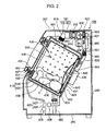
- FIG. 2 is a schematic cross-sectional view of the washing and drying machine 100 with the door 300 at the closing position. Arrangements, shapes and structures of elements in the main housing 200, which are shown in FIG. 2 , should not be interpreted in a limited way. The arrangements, shapes and structures of the elements in the main housing 200 may be appropriately defined according to designs and functions of the laundry drying processor. The entire structure of the washing and drying machine 100 is further described with reference to FIGS. 1 and 2 .
- a laundry processor 400 configured to perform a drying process is constructed in the main housing 200.
- the laundry processor 400 executes various processes required for washing and drying laundry C, such as drying, washing, rinsing and spin-drying processes. If a laundry dryer without a washing function is used as the laundry drying processor, the laundry processor may perform only the drying process.
- the laundry processor 400 comprises the aforementioned washing and drying tub 410.
- the washing and drying tub 410 includes a one-end bottomed cylindrical water tub 420 which is supported but allowed to rock in the main housing 200, and a one-end bottomed cylindrical rotary drum 440 which is supported in the water tub 420.
- the laundry processor 400 comprises a suspension 490 configured to elastically support the washing and drying tub 410.
- the suspension 490 connected to the bottom wall 260 of the main housing 200 appropriately absorbs vibrations generated during various processes such as the aforementioned drying, washing, rinsing and spin-drying processes.
- the laundry processor 400 further includes a motor 430 configured to rotate the rotary drum 440.
- the main body of the motor 430 is mounted to the outer surface of the bottom wall 431 of the water tub 420.
- the rotating shaft of the motor 430 pierces through the bottom wall 431 of the water tub 420 and is connected to the bottom wall 432 of the rotary drum 440.
- the motor 430 rotates the rotary drum 440 during the various processes such as the drying, washing, rinsing and spin-drying processes.
- An opening 434 substantially concentric with the substantially circular door 300 at the closing position is formed on a front wall 433 opposite to the bottom wall 431 of the water tub 420.
- an opening 436 substantially concentric with the opening 434 formed on the front wall 433 of the water tub 420 is formed on a front wall 435 opposite to the bottom wall 432 of the rotary drum 440.
- a user may move the door 300 to the opening position to feed the laundry C into the rotary drum 440 through the feed port 215.
- the laundry processor 400 further comprises a bellows 437 situated between the central wall 212 of the main housing 200 and the front wall 433 of the water tub 420.
- the water tub 420 is elastically connected to the main housing 200 by the bellows 437.
- the door 300 includes a one-end bottomed transparent window 310 which looks like a substantially trapezoidal cone, and a substantially disc-shaped support frame 320 which supports the window 310.
- the window 310 is inserted into the feed port 215 formed on the main housing 200. A user may see the laundry C inside the washing and drying tub 410 through the transparent window 310 while the door 300 is at the closing position.
- the water tub 420 is provided with a discharge port 423, from which washing water is discharged, and an inflow port 424, into which the washing water flows.
- the washing water used for washing the laundry is circulated between the discharge port 423 and the inflow port 424.
- the washing and drying machine 100 comprises a pipeline 425, which defines a circulation path for the washing water between the discharge port 423 and the inflow port 424.
- the pipeline 425 includes an upstream pipeline 426 and downstream pipeline 427. One end of the upstream pipeline 426 is connected to the discharge port 423. The other end of the upstream pipeline 426 is connected to the bottom wall 260 of the main housing 200.
- One end of the downstream pipeline 427 is connected to the middle of the upstream pipeline 426. The other end of the downstream pipeline 427 is connected to the inflow port 424.
- the washing and drying machine 100 comprises a circulation pump 428, which circulates the washing water between the discharge and inflow ports 423, 424, and a drain valve 429 which controls drainage of the washing water outside the main housing 200.
- the circulation pump 428 and the drain valve 429 are mounted to the upstream pipeline 426.
- the circulation pump 428 is situated before a connection between the upstream and downstream pipelines 426, 427.
- the drain valve 429 is situated after the circulation pump 428.
- the drain valve 429 is closed while the washing and drying machine 100 executes a process, which requires accumulation of a predetermined amount of water in the washing and drying tub 410 (e.g., the washing or rinsing process).
- the circulation pump 428 is activated as appropriate to circulate the washing water between the discharge and inflow ports 423, 424.
- the drain valve 429 is opened.
- the washing water inside the washing and drying tub 410 is drained from the bottom wall 260 to the outside of the main housing 200 through the upstream pipeline 426.
- the washing and drying machine 100 comprises a circulator 600 configured to circulate dry air for drying the laundry C, which is stored in the rotary drum 440.
- the water tub 420 includes a cylindrical circumferential wall 438 extending between the bottom and front walls 431, 433.
- the circumferential wall 438 of the water tub 420 is provided with an exhaust port 601, through which the dry air is exhausted from the washing and drying tub 410.
- An intake port 643 through which the dry air is sucked into the washing and drying tub 410 is formed on the bottom wall 431 of the water tub 420.
- the circulator 600 circulates the dry air between the exhaust and intake ports 601, 643.
- a bottom hole 645 is formed on the bottom wall 432 of the rotary drum 440 to guide the dry air sucked through the intake port 643 into the rotary drum 440.
- the rotary drum 440 includes a cylindrical circumferential wall 439 extending between the bottom and front walls 432, 435.
- a lot of circumferential holes 646 are formed on the circumferential wall 439 of the rotary drum 440 to guide the dry air to the exhaust port 601 formed on the circumferential wall 438 of the water tub 420.
- the dry air flowing from the bottom hole 645 to the circumferential holes 646 dries the laundry C inside the rotary drum 440.
- the washing and drying tub 410 used for the drying process is exemplified as the drying tub.
- the circulator 600 configured to circulate the dry air in the main housing 200 comprises a first pipeline 610 extending from the exhaust port 601 toward the top wall 250 of the main housing 200, a filter device 700 connected to the first pipeline 610, and a heat pump 630 adjacent to the filter device 700.
- the top wall 250 includes a substantially rectangular main wall 252 which forms most of the upper surface of the main housing 200 and a substantially rectangular cover mechanism 800 surrounded by the main wall 252.
- the filter device 700 is adjacent to the cover mechanism 800.
- Lint (dust such as yam wastes) is separated from the laundry C during the drying process performed in the rotary drum 440.
- the lint is introduced to the filter device 700 through the first pipeline 610 by the dry air flow.
- the filter device 700 is configured to remove the lint in the dry air.
- the filter device 700 is exemplified as the removal device.
- the filter device 700 is connected to the cover mechanism 800, which may be attached to or detached from the main wall 252. If the cover mechanism 800 is removed from the main wall 252, the filter device 700 is taken out from the main housing 200 with the cover mechanism 800. A user may thereafter remove lint accumulated in the filter device 700.
- the heat pump 630 may be a general heat exchanger.
- the heat pump 630 comprises a dehumidifier 635 which cools dry air to remove moisture in the dry air, and a heater 633 which heats the dry air passing through the dehumidifier 635.
- the dehumidification by the dehumidifier 635 and the heating by the heater 633 are accomplished by increasing/decreasing pressure applied to coolant, which passes through the dehumidifier 635 and the heater 633.
- the heat pump 630 is exemplified as the dehumidifying heater.
- the dehumidifying heater may be a device such as the heat pump 630 with the dehumidifier 635 and the heater 633 incorporated therein.
- the dehumidifying heater may include a dehumidifier for dehumidification and a heater separately provided from the dehumidifier.
- the circulator 600 comprises a blower 621 configured to blow the dry air after the dehumidification and heating by the heat pump 630 to the intake port 643, and a second pipeline 620 configured to guide the dry air blown by the blower 621 to the intake port 643.
- the blower 621 causes negative pressure on the upstream side of the blower 621 and positive pressure on the downstream side of the blower 621. As a result, dry air circulation is effected between the exhaust and intake ports 601, 643.
- the blower 621 is exemplified as the air supplier.
- the circulator 600 comprises a branched pipeline 650 branching from the second pipeline 620, and a switch valve 651 situated at a connection between the second pipeline 620 and the branched pipeline 650.
- the branched pipeline 650 includes a tip end which is communicated with the opening 436 formed on the front wall 435 of the rotary drum 440.
- the switch valve 651 is turned between a first position where the switch valve 651 blocks the dry air flowing from the blower 621 toward the intake port 643, and a second position where the switch valve 651 allows the dry air flowing from the blower 621 to further flow toward the intake port 643.
- the switch valve 651 is set at the first position, most of the dry air is blown from the opening 436 of the rotary drum 440 to the laundry C through the branched pipeline 650. If the switch valve 651 is set at the second position, most of the dry air flows toward the intake port 643. For example, after the drying process is started, the switch valve 651 is set at the second position for a predetermined period of time. Thereafter, the switch valve 651 is set at the first position until the end of the drying process. Thus, drying operations are changed in response to how much the laundry C is dried.
- An external air introduction mechanism configured to cool the heat pump 630 is described with reference to FIGS. 1 and 2 .
- external air which exists outside the main housing 200 is introduced as cooling air into the main housing 200 in order to maintain heat-exchange efficiency of the heat pump 630.
- the external air introduction mechanism 150 includes the aforementioned filter device 700 and the cover mechanism 800 situated above the filter device 700. As described above, the cover mechanism 800 is attached to the top wall 250 of the main housing 200.
- FIG. 3 is an enlarged perspective view of the top wall 250.
- the external air introduction mechanism 150 is further described with reference to FIGS. 1 to 3 .
- a substantially rectangular ejection port 251 is formed on the top wall 250.
- the ejection port 251 is used to take the filter device 700 in and out of the main housing 200.
- the cover mechanism 800 is connected to the filter device 700 as described later. Therefore, a user may remove the cover mechanism 800 from the ejection port 251 to take the filter device 700 in and out of the main housing 200 via the ejection port 251.
- the user may connect the cover mechanism 800 to the filter device 700 and attach the cover mechanism 800 to the ejection port 251 to dispose the filter device 700 in position inside the main housing 200, in which the laundry C is stored.
- the cover mechanism 800 includes a cover plate 810 with a complementary outer surface 813 to the ejection port 251, and a pivotal lever plate 820 attached to the cover plate 810.
- the cover plate 810 appropriately closes the ejection port 251.
- machine sound or flow sound which are generated from various elements stored in the main housing 200 (e.g., the washing and drying tub 410, the filter device 700, the heat pump 630, and the blower 621), leaks.
- a suction port is formed between the cover plate 810 and the lever plate 820 to introduce external air into the main housing 200 as described later.
- An external air inlet is formed in the filter device 700, which is communicated with the suction port.
- the external air taken into the main housing 200 via the external air inlet of the filter device 700 is used for cooling the heat pump 630.
- the cover mechanism 800 is exemplified as the cover element.
- the outer surface 813 of the cover plate 810 is exemplified as the first outer surface.
- FIG. 4 is a front view of the external air introduction mechanism 150.
- FIG. 5 is a cross-sectional view of the external air introduction mechanism 150 along line A-A shown in FIG. 4 .
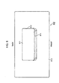
- FIG. 6 is a plan view of the cover plate 810. The suction port between the cover plate 810 and the lever plate 820 is described with reference to FIGS. 1 and 4 to 6 .
- the cover plate 810 of the cover mechanism 800 is attached to an upper portion of the filter device 700.
- the cover plate 810 includes an attachment edge 812, which forms a complementary attachment port 811 to the lever plate 820.
- the attachment edge 812 contours a substantially rectangular closed loop.
- the lever plate 820 closes the attachment port 811.
- the lever plate 820 includes a base edge 821 at the back side of the washing and drying machine 100, a tip edge 822 opposite to the base edge 821 (i.e., the front side), and an outer surface 823 extending between the base and tip edges 821, 822.
- the base edge 821 extends along a rotation axis of the lever plate 820.
- the outer surface 823 of the lever plate 820 is exemplified as the second outer surface.
- the lever plate 820 vertically turns around the rotation axis near the base edge 821. Therefore, a user may push the lever plate 820 downward to grab the cover plate 810.
- the tip edge 822 is situated below the attachment edge 812 (i.e., inside the main housing 200).
- the outer surface 823 of the lever plate 820 includes a base surface 824 extending from the base edge 821 forward along the outer surface 813 of the cover plate 810, and a curved and inclined surface 825, which extends from the tip edge 822 toward the base surface 824.
- a space between the inclined surface 825 and the attachment edge 812 is used as a suction port 830 through which the external air is suctioned.
- the suction port 830 is opened in an opposite direction to the front wall 210 (i.e. toward the back wall 220).
- the suction port 830 which is opened obliquely upward, mainly defines a transmission direction of sound generated inside the main housing 200 backward. Thus it becomes less likely that the sound is transmitted to a user working nearby the front wall 210.
- the attachment edge 812 includes a ridged edge 814, which protrudes upward.
- the ridged edge 814 is situated above the tip edge 822 of the lever plate 820. Due to the ridged edge 814, it becomes less likely that, for example, water dripping from laundry, which is placed on the top wall 250 by the user, flows into the suction port 830.
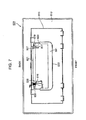
- FIG. 7 is a bottom view of the cover mechanism 800. Angular motions of the lever plate 820 are described with reference to FIGS. 5 and 7 .
- the lever 820 includes a first shaft piece 826 and a second shaft piece 827, which are situated near the base edge 821.
- the first and second shaft pieces 826, 827 project downward from a bottom surface of the lever plate 820.
- the first shaft piece 826 includes a substantially cylindrical first shaft 828.
- the second shaft piece 827 includes a substantially cylindrical second shaft 829 shorter than the first shaft 828.
- the first and second shafts 828, 829 extend along the base edge 821.
- the cover plate 810 includes an attachment wall 815, which contours a substantially rectangular loop.
- the attachment wall 815 projects downward from the bottom surface of the cover plate 810.
- the attachment wall 815 includes a first bearing piece 816 which supports the rotatable first shaft 828, and a second bearing piece 817 which supports the rotatable second shaft 829.
- the first and second bearing pieces 816, 817 protrude forward from an inner surface of the attachment wall 815 adjacent to the base edge 821 of the lever plate 820.
- the pivotal lever plate 820 is attached to the cover plate 810.
- the first and second shafts 828, 829 which are aligned along the base edge 821 of the lever plate 820, define the rotation axis of the lever plate 820.
- the cover mechanism 800 comprises a twisted coil spring 840 wrapped around the first shaft 828.
- One end of the twisted coil spring 840 is connected to the bottom surface of the cover plate 810.
- the other end of the twisted coil spring 840 is connected to the bottom surface of the lever plate 820. Accordingly, the twisted coil spring 840 pushes the tip edge 822 of the lever plate 820 upward to bias the lever plate 820.
- the twisted coil spring 840 is exemplified as the biasing element.
- the lever plate 820 includes a substantially U-shaped positioning piece 891.
- the positioning piece 891 forms the tip edge 822 and a part of side edges of the lever plate 820.
- the positioning piece 891 partially overlaps with the cover plate 810.
- the positioning piece 891 therefore appropriately limits the upward angular motion of the lever plate 820, which is caused by the biasing force of the twisted coil spring 840.
- FIG. 8 is a plan view of the filter device 700. The connection between the cover mechanism 800 and the filter device 700 is described with reference to FIGS. 1 , 2 , 4 , 5 , 7 and 8 .
- the filter device 700 comprises a housing 710.
- the housing 710 includes an inlet 712 through which dry air discharged from the exhaust port 601 is introduced, and an external air inlet 725 through which external air existing outside the main housing 200 is introduced.
- An outlet 713 opposite to the inlet 712 is formed on the housing 710.
- a right-angled grid of supporting part 714 is formed on the outlet 713.
- a filter mesh 720 (see FIG. 5 ) is attached along the supporting part 714.
- the dry air guided from the exhaust port 601 to the filter device 700 by the first pipeline 610 is introduced into the housing 710 via the inlet 712. Subsequently, the dry air is discharged from the outlet 713 opposite to the inlet 712.
- the filter mesh 720 filters the dry air to preferably capture lint floating in the dry air.
- the heat pump 630 is situated immediately after the outlet 713. Therefore, the dry air is discharged from the outlet 713 to the heat pump 630 after the lint removal from the dry air.
- the filter mesh 720 is exemplified as the filter element.
- the direction of the dry air flowing from the inlet 712 to the outlet 713 i.e., the direction from the front wall 210 to the back wall 220
- the first direction is referred to as the first direction.
- the housing 710 includes a first housing wall 715 on which the inlet 712 and the external air inlet 725 are formed, and a second housing wall 716 on which the outlet 713 is formed.
- the first housing wall 715 includes a connection wall 717, which has a substantially U-shaped cross section, to connect the cover mechanism 800 with the housing 710. As shown in FIG. 5 , a space R1 which allows the lever plate 820 to pivot is formed between the connection wall 717, which is curved downward, and the flat cover plate 810.
- connection wall 717 includes a rib 718 which protrudes upward.
- the rib 718 is formed along the backside edge of the connection wall 717.
- the attachment wall 815 of the cover plate 810 configured to cover the connection wall 717 is adjacent to the rib 718.
- the attachment wall 815 and the rib 718 are coupled to each other by means of a suitable fixture such as a screw or bolt.
- the attachment wall 815 is exemplified as the connection portion.
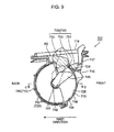
- FIG. 9 is a cross-sectional view of the filter device 700 along line B-B shown in FIG. 8 . Introduction of the external air into the housing 710 is described with reference to FIGS. 1 , 5 , 8 and 9 .
- the first housing wall 715 includes a partition wall 719 extending in the first direction.
- the partition wall 719 divides the space between the cover plate 810 and the connection wall 717 into the space R1 in which the lever plate 820 is turned and a space R2 into which the external air flows.
- the space R2 is communicated with the suction port 830 via a gap between the upper edge of the partition wall 719 and the cover plate 810.
- the substantially rectangular external air inlet 725 is formed on the connection wall 717 which defines the space R2.
- a space between the suction port 830 and the external air inlet 725 i.e., the space between the cover plate 810 and the connection wall 717) is partially partitioned by the partition wall 719, which projects upward from the upper surface of the connection wall 717. Due to the partition wall 719, it becomes less likely that liquid dropping down from the suction port 830 onto the connection wall 717 flows into the external air inlet 725.
- the filter device 700 includes a gating mechanism 730 configured to open/close the external air inlet 725.
- the gating mechanism 730 includes a valve piece 735.
- the valve piece 735 includes a base 731, which is fitted into an opening nearby the external air inlet 725, a plug 732 which is displaced between a closing position where the plug 732 closes the external air inlet 725 and an opening position where the plug 732 opens the external air inlet 725, and a thinner portion 733 between the base 731 and the plug 732.
- the valve piece 735 is exemplified as the valve. It should be noted that that the plug 732 at the opening position is shown by a dotted line in FIG. 9 .
- the base 731 which looks like a substantially rectangular block, is fixedly attached to the connection wall 717.
- the plug 732 which looks like a substantially rectangular block, partially projects into the internal space of the housing 710 through the external air inlet 725.
- the plug 732 is pivoted around the thinner portion 733 between the opening and closing positions. If the plug 732 is at the opening position, the external air flows into the housing 710 via the external air inlet 725 in fluid communicated with the outside of the main housing 200 via the suction port 830.
- the thinner portion 733 is exemplified as the hinge.
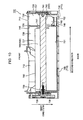
- FIG. 10 is a cross-sectional view of the filter device 700 along line C-C shown in FIG. 9 .
- the gating mechanism 730 is described with reference to FIGS. 5 , 9 and 10 .
- the housing 710 includes an inner wall surface 726 which defines a substantially cylindrical internal space of the housing 710.
- the internal space formed by the inner wall surface 726 extends in the second direction, which is substantially perpendicular to the first direction.
- the housing 710 includes an annular partition plate 729, which partitions the internal space extending in the second direction into a first chamber 727 and a second chamber 728.
- the first chamber 727 is communicated with the inlet 712, so that the dry air flows in the first chamber 727.
- the second chamber 728 is communicated with the external air inlet 725. Therefore, the external air flows in the second chamber 728 while the plug 732 is at the opening position.
- the filter device 700 includes a rotating shaft 740 configured to rotate in the housing 710.
- the first housing wall 715 includes a first side wall 736 and a second side wall 737, which extend between the inlet 712 and the outlet 713.
- a gear 738 is attached to the outer surface of the first side wall 736.
- the gear 738 includes a gear shaft 739 inserted into a through-hole, which is formed on the first side wall 736.
- the gear shaft 739 is inserted into a concavity formed on one end of the rotating shaft 740.
- a suitable fixture such as a screw or bolt is screwed along longitudinal directional axes of the gear shaft 739 and the rotating shaft 740, so that the gear 738 and the rotating shaft 740 are appropriately connected to each other.
- a motor or another appropriate driver is connected to the gear 738. Drive force is transmitted to the gear 738 to appropriately rotate the rotating shaft 740 in the housing 710.
- the second side wall 737 includes a boss 741, which is inserted into a concavity formed on the other end of the rotating shaft 740 to support the rotating shaft 740.
- the gating mechanism 730 includes a cam piece 745, which projects from the circumferential surface of the rotating shaft 740 in the second chamber 728.
- the cam piece 745 which rotates along with the rotating shaft 740, comes into contact with the plug 732 at the closing position.
- the plug 732 into contact with the cam piece 745 is pushed upward, so that the plug 732 is turned upward around the thinner portion 733 and displaced to the opening position.
- the plug 732 is disconnected from the cam piece 745, the plug 732 is turned downward around the thinner portion 733 by its own weight, and then displaced to the closing position.
- the gating mechanism 730 may open/close the external air inlet 725 in response to rotation of the rotating shaft 740.
- the partition plate 729 includes an outer rim 746 connected to the inner wall surface 726 of the housing 710, and an inner rim 747 defining an opening into which the rotating shaft 740 is inserted.
- the rotating shaft 740 extends across the opening defined by the inner rim 747.
- An annular gap formed between the inner rim 747 and the rotating shaft allows communication between the first and second chambers 727, 728.
- the dry air flowing from the inlet 712 toward the outlet 713 causes negative pressure in the second chamber 728.
- the external air flows from the suction port 830 into the second chamber 728 while the cam piece 745 lifts the plug 732.
- the outlet 713 includes a first outlet 748 which is used to discharge the dry air flowing from the inlet 712 into the first chamber 727 to the heat pump 630, and a second outlet 749 which is used to discharge the external air flowing into the second chamber 728 to the heat pump 630.
- the filter mesh 720 includes a first filter 751 covering the first outlet 748 (see FIG. 5 ) and a second filter 752 covering the second outlet 749 (see FIG. 9 ).
- the first filter 751 is used to filter the dry air flowing from the inlet 712 to remove lint floating in the dry air. After the lint removal, the dry air is directly supplied to the heat pump 630 (i.e., without passing through the blower 621).
- the second filter 752 is used to filter the external air flowing from the external air inlet 725 to remove foreign objects (e.g., dust) floating in the external air. After the removal of the foreign objects from the external air, the external air is directly supplied to the heat pump 630 (i.e., without passing through the blower 621).
- foreign objects e.g., dust
- An adjuster configured to adjust a direction of the dry air flowing from the inlet 712 to the outlet 713 is described with reference to FIGS. 5 and 10 .
- the filter device 700 comprises an adjuster 500 configured to adjust a direction of the dry air flowing from the inlet 712 to the outlet 713.
- the adjuster 500 comprises the aforementioned rotating shaft 740 and an adjustment piece 765 extending from the rotating shaft 740.
- the adjustment piece 765 is rotated as the rotating shaft 740 rotates in the housing 710.
- the adjustment piece 765 is made of a substantially rectangular plate material. In the present embodiment, the adjustment piece 765 is exemplified as the adjustment plate.
- the housing 710 includes an upper stopper pin 773 and a lower stopper pin 774, which project from the inner wall surface 726 toward the outlet 713.
- the upper stopper pin 773 is formed above the inlet 712.
- the lower stopper pin 774 is formed below the inlet 712.
- the adjustment piece 765 includes a tip end 766 which turns between the upper and lower stopper pins 773, 774. If the adjustment piece 765 moves upward, the tip end 766 abuts the upper stopper pin 773 to limit the upward movement of the adjustment piece 765. If the adjustment piece 765 moves downward, the tip end 766 abuts the lower stopper pin 774 to limit the downward movement of the adjustment piece 765.
- the upper and/or lower stopper pins 773, 774 are exemplified as the limiter.
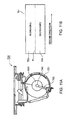
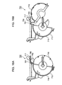
- FIGS. 11A to 12B schematically show operations performed by the adjuster 500.
- FIGS. 11A and 12A are schematic cross-sectional views of the filter device 700.
- FIGS. 11B and 12B show the first filter 751. The operations of the adjuster 500 are described with reference to FIGS. 10 to 12B .
- the adjustment piece 765 shown in FIG. 11A projects downward from the rotating shaft 740, so that the tip end 766 abuts the lower stopper pin 774.
- the adjustment piece 765 shown in FIG. 12A is more horizontal than the adjustment piece 765 shown in FIG. 11A .
- the rotating shaft 740 extends in the second direction.
- the first filter 751 extends in the second direction, like the rotating shaft 740.
- FIGS. 11B and 12B shows a phantom line FL, which divides the first filter 751 into upper and lower areas.
- the phantom line FL defines an upper area 753 extending along the extension direction of the rotating shaft 740, and a lower area 754 extending along the upper area 753.
- the upper area 753 is exemplified as the first area while the lower area 754 is exemplified as the second area.
- the adjustment piece 765 projecting downward from the rotating shaft 740 interferes with the dry air, which tries to flow below the rotating shaft 740. As a result, most of the dry air is guided upward. Consequently, a decreased amount of the dry air passes through the lower area 754 whereas an increased amount of the dry air passes through the upper area 753.
- the adjustment piece 765 shown in FIGS. 12A and 12B allows the dry air to flow more smoothly. Therefore, if the adjustment piece 765 moves from the position shown in FIGS. 11A and 11B to the position shown in FIGS. 12A and 12B , a larger amount of the dry air passes through the lower area 754 whereas a smaller amount of the dry air passes through the upper area 753.
- the adjustment piece 765 may change amounts of the dry air passing through the upper and lower areas 753, 754 in response to the rotation of the rotating shaft 740.
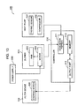
- FIG. 13 is a block diagram of elements used for controlling the filter device 700. The control for the filter device 700 is described with reference to FIGS. 2 and 11A to 13 .
- the washing and drying machine 100 comprises a controller 510 configured to control the adjuster 500.
- the adjuster 500 includes a stepping motor 520 configured to rotate the rotating shaft 740.
- the controller 510 controls the stepping motor 520, which engages with the gear 738 described in the context of FIG. 10 , to adjust the dry air flow in the filter device 700.
- the stepping motor 520 is exemplified as the drive source.
- another drive element configured to rotate the rotating shaft 740 may be used as the drive source.
- the blower 621 comprises a fan 622 and a motor 623 configured to rotate the fan 622.
- the motor 623 rotating the fan 622 keeps an amount of the dry air at a predetermined level while the dry air is circulated in the washing and drying machine 100.
- the washing and drying machine 100 comprises a power supply 530 configured to supply power to the motor 623.
- the controller 510 controls the stepping motor 520 in response to the power from the power supply 530 to the motor 623.
- the controller 510 reads or receives a value of current flowing from the power supply 530 to the motor 623 to control the stepping motor 520, so that the current value is decreased (i.e., to decrease the power). For instance, if lint is more stacked on the upper area 753 of the first filter 751 than the lower area 754, the position of the adjustment piece 765 may be preferably set to allow more dry air to pass through the lower area 754 rather than the upper area 753, so that the same amount of the dry air is circulated at a low current value. Therefore, in this case, the controller 510 adjusts the position of the adjustment piece 765 so that more dry air passes through the lower area 754.
- the heat pump 630 has a thermo-sensor 631 configured to detect a temperature of the coolant used for the heat exchange with the dry air, and a compressor 632 configured to compress the coolant.
- the controller 510 controls the stepping motor 520 in response to the temperature of the coolant detected by the thermo-sensor 631 and a number of revolutions of the compressor 632 to move the plug 732 to the opening or closing position.
- the controller 510 has an acquisition portion 511 configured to read or receive the value of the current flowing from the power supply 530 to the motor 623.
- the acquisition portion 511 also receives an output signal from the thermo-sensor 631.
- the acquisition portion 511 reads or receives the number of revolutions of the compressor 632.
- the value of the current flowing from the power supply 530 to the motor 623 is exemplified as the power information.
- the output signal from the thermo-sensor 631 and/or the number of revolutions of the compressor 632 is exemplified as the temperature information.
- the controller 510 comprises an output port 512 from which an operation signal for operating the stepping motor 520 is output.
- the operation signal includes a first operation signal for rotating the rotating shaft 740 in a predetermined rotation range defined by the upper and/or lower stopper pins 773, 774. While the rotating shaft 740 is rotated in the predetermined rotation range in response to the first operation signal, the acquisition portion 511 reads current values supplied to the blower 621.
- a reference position for the rotation of the rotating shaft 740 is set at, for example, a position where the adjustment piece 765 abuts the upper and/or lower stopper pins 773, 774.
- the stepping motor 520 rotates the rotating shaft 740 in the predetermined rotation range in response to the first operation signal.
- the acquisition portion 511 monitors the current values obtained during the rotation of the rotating shaft 740 to identify a period from when the rotating shaft 740 starts rotating to when the minimum current value is recorded. In the present embodiment, data on the period identified by the acquisition portion 511 is exemplified as positional information related to the position of the adjustment piece 765.
- the controller 510 comprises a memory 513 configured to store the data on the period identified by the acquisition portion 511.
- the operation signal includes a second operation signal for moving the adjustment piece 765 to a position where the power becomes the lowest during the rotation of the rotating shaft 740 in response to the first operation signal.
- the position of the adjustment piece 765 where the power becomes the lowest during the rotation of the rotating shaft 740 is identified on the basis of the data on the period.
- the second operation signal is output from the output port 512 to the stepping motor 520 after completion of the rotation of the rotating shaft 740 in response to the first operation signal. As a result, the adjustment piece 765 is moved to the position where the power supplied to the blower 621 becomes the lowest.
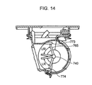
- FIG. 14 is a schematic cross-sectional view of the external air introduction mechanism 150. The control performed by the controller 510 is further described with reference to FIGS. 9 , 13 and 14 .
- the rotation range of the rotating shaft 740 includes an upper rotation range UR and a lower rotation range LR.
- the upper rotation range UR is defined as a range from where the adjustment piece 765 abuts the upper stopper pin 773 to where the adjustment piece 765 then moves downward, for example, by approximately 60°.
- the lower rotation range LR is defined as a range from where the adjustment piece 765 abuts the lower stopper pin 774 to where the adjustment piece 765 then moves upward, for example, by approximately 49°.
- the plug 732 is kept at the opening position while the rotating shaft 740 rotates within the upper rotation range UR.
- the plug 732 is kept at the closing position while the rotating shaft 740 rotates within the lower rotation range LR.
- the lower rotation range LR is exemplified as the first range while the upper rotation range UR is exemplified as the second range.
- the aforementioned first operation signal includes a first mode signal for rotating the rotating shaft 740 within the lower rotation range LR, and a second mode signal for rotating the rotating shaft 740 within the upper rotation range UR.
- the acquisition portion 511 determines whether the heat pump 630 has to be cooled or not, on the basis of the output signal from the thermo-sensor 631 and/or the number of revolutions of the compressor 632. Unless the heat pump 630 has to be cooled, the acquisition portion 511 selects a first mode in which the rotating shaft 740 rotates within the lower rotation range LR. If the heat pump 630 has to be cooled, the acquisition portion 511 selects a second mode in which the rotating shaft 740 rotates within the upper rotation range UR. As a result, the plug 732 moves to the opening position, so that the external air is supplied to the heat pump 630.
- the output port 512 selectively outputs the first or second mode signal in response to the determination made by the acquisition portion 511.
- the rotating shaft 740 rotates within the upper or lower rotation range UR, LR.
- the acquisition portion 511 monitors the current values obtained during the rotation of the rotating shaft 740 to identify a period from when the rotating shaft 740 starts rotating to when the minimum current value is recorded.
- the memory 513 stores the period from when the rotating shaft 740 starts rotating to when the minimum current value is recorded.
- the output port 512 thereafter outputs the second operation signal. Consequently, the adjustment piece 765 moves to the position where the power supplied to the blower 621 becomes the lowest.
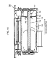
- FIG. 15 is a cross-sectional view of the filter device 700 along a longitudinal directional axis of the rotating shaft 740.
- the rotating shaft 740 is described with reference to FIG. 15 .
- the inner rim 747 of the partition plate 729 defines the opening which allows the communication between the first and second chambers 727, 728.
- the rotating shaft 740 includes an annular projection 775 adjacent to the opening defined by the inner rim 747.
- the annular projection 775 which is substantially the same size as the opening, includes a periphery 776 along the inner rim 747 of the partition plate 729. Therefore, it is likely that the annular projection 775 prevents the lint in the dry air flowing in the second direction from entering the second chamber 728 from the first chamber 727. It should be noted that there is a small gap between the partition plate 729 and the annular projection 775. The gap between the partition plate 729 and the annular projection 775 keeps the communication between the first and second chambers 727, 728.
- FIGS. 16A and 16B are schematic cross-sectional views showing the housing 710 of the filter device 700.
- FIG. 16A shows the housing 710 in use.
- FIG. 16B shows the disassembled housing 710. The housing 710 is described with reference to FIGS. 16A and 16B .
- the second housing wall 716 is attached and pivotal with respect to the first housing wall 715.
- a connector 780 configured to connect the first housing wall 715 to the second housing wall 716 is provided below the connection wall 717 of the first housing wall 715.
- the second housing wall 716 includes, for example, a connecting plate 781 situated immediately below the connection wall 717 and a pin 782 projecting from the connecting plate 781.
- the connection wall 717 holds the rotatable pin 782.
- a user may turn the second housing wall 716 to preferably remove the lint accumulated in the housing 710.
- the aforementioned embodiment mainly includes a laundry drying processor with the following configurations.
- the laundry drying processor with the following configurations may achieve power saving.
- a laundry drying processor has: a drying tub including an intake port into which dry air for drying laundry flows and an exhaust port from which the dry air is exhausted; a removal device configured to remove lint from the dry air exhausted from the exhaust port; a dehumidifying heater configured to dehumidify and heat the dry air after lint removal by the removal device; an air supplier configured to send a predetermined amount of the dry air subjected to dehumidification and heating by the dehumidifying heater, to the intake port; and a power supply configured to supply power to operate the air supplier, wherein the removal device includes: a housing having an inlet into which the dry air exhausted from the exhaust port is introduced and an outlet from which the dry air is discharged to the dehumidifying heater; a filter element attached to the outlet to remove the lint from the dry air; an adjuster configured to adjust a flow direction of the dry air flowing from the inlet to the filter element; and a controller configured to control the adjuster, the adjuster
- the dry air flows into the drying tub via the intake port.
- the dry air is then discharged from the drying tub via the exhaust port.
- the laundry in the drying tub is dried.
- the removal device removes the lint from the dry air discharged from the drying tub.
- the dehumidifying heater dehumidifies and heats the dry air.
- the power supply supplies power to the air supplier configured to send a predetermined amount of the dehumidified and heated dry air to the intake port of the drying tub. As a result, the dry air is sent to the inflow port and reused for drying the laundry inside the drying tub.
- the housing of the removal device is provided with the inlet through which the dry air exhausted from the exhaust port is introduced and the outlet through which the dry air is discharged to the dehumidifying heater.
- the filter element attached to the outlet removes the lint from the dry air.
- the adjuster configured to adjust the flow direction of the dry air flowing from the inlet toward the filter element includes the rotating shaft rotating in the housing, and the adjustment plate extending from the rotating shaft.
- the filter element includes the first area extending in the extension direction of the rotating shaft, and the second area extending along the first area.
- the controller controls the drive source in response to the power to change the amounts of the dry air passing through the first and second areas.
- the adjustment plate may be adjusted so that the dry air flow becomes less sensitive to the lint inside the filter device. Thus the power is unnecessarily supplied to the air supplier, which results in power saving of the laundry drying processor.
- the controller controls the drive source so as to reduce the power.
- the controller controls the drive source so as to reduce the power, which results in power saving of the laundry drying processor.
- the housing includes a limiter which comes into contact with the adjustment plate to limit a rotation range of the rotating shaft.
- the limiter comes into contact with the adjustment plate to limit the rotation range of the rotating shaft.
- the adjustment plate is adjusted within the rotation range defined by the limiter so that the dry air flow becomes less sensitive to the lint inside the filter device. Accordingly, it becomes less likely that the power is unnecessarily supplied to the air supplier, which results in power saving of the laundry drying processor.
- the controller includes an output port from which an operation signal for operating the drive source is output, an acquisition portion which acquires power information on the power, and a memory configured to store positional information on a position of the adjustment plate where the power becomes minimal within the rotation range
- the operation signal includes a first operation signal for rotating the rotating shaft in the rotation range, and a second operation signal for rotating the rotating shaft so that the adjustment plate moves to the position where the power becomes minimal within the rotation range
- the output port outputs the first operation signal
- the acquisition portion acquires the power information while the rotating shaft is rotated and the memory stores the positional information on the basis of the power information
- the output port outputs the second operation signal on the basis of the positional information
- the drive source rotates the rotating shaft to move the adjustment plate to the position according to the positional information in response to the second operation signal.
- the controller includes the output port from which an operation signal for operating the drive source is output, the acquisition portion configured to acquire power information on the power, and the memory configured to store positional information on a position of the adjustment plate where the power becomes minimal within the rotation range.
- the operation signal includes the first operation signal for rotating the rotating shaft in the rotation range, and the second operation signal for rotating the rotating shaft so that the adjustment plate moves to the position where the power becomes minimal within the rotation range. If the output port outputs the first operation signal, the acquisition portion acquires the power information while the rotating shaft is rotated, and the memory stores the positional information on the basis of the power information. The output port outputs the second operation signal on the basis of the positional information.
- the drive source rotates the rotating shaft to move the adjustment plate to the position according to the positional information in response to the second operation signal.
- the adjustment plate is adjusted so that the dry air flow becomes less sensitive to the lint inside the filter device. Accordingly it becomes less likely that the power is unnecessarily supplied to the air supplier, which results in power saving of the laundry drying processor.
- the laundry drying processor further have a main housing configured to store the drying tub, the removal device the dehumidifying heater and the air supplier, wherein the housing is provided with an external air inlet through which external air existing outside the main housing is introduced, the removal device includes a valve which has a plug displaced between a closing position where the plug closes the external air inlet and an opening position where the plug opens the external air inlet, and a cam piece connected to the rotating shaft, and the cam piece displaces the plug between the closing position and the opening position in response to rotation of the rotating shaft.
- the eternal air existing outside the main housing which stores the drying tub, the removal device, the dehumidifying heater and the air supplier, is introduced through the external air inlet formed on the housing.
- the cam piece connected to the rotating shaft displaces the plug of the valve between the closing position where the plug closes the external air inlet and the opening position where the plug opens the external air inlet. If the dehumidifying heater has to be cooled, the external air inlet is opened. As a result, the dehumidifying heater is appropriately cooled. Thus, drying functions are appropriately maintained over a relatively long period of time.
- the rotation range of the rotating shaft includes a first range in which the plug is kept at the closing position, and a second range in which the plug is kept at the opening position
- the acquisition portion acquires temperature information on a temperature of the dehumidifying heater
- the first operation signal includes a first mode signal for rotating the rotating shaft in the first range and a second mode signal for rotating the rotating shaft in the second range
- the output port selectively outputs the first mode signal and the second mode signal on the basis of the temperature information.
- the rotation range of the rotating shaft includes the first range in which the plug is kept at the closing position, and the second range in which the plug is kept at the opening position.
- the acquisition portion acquires temperature information on a temperature of the dehumidifying heater.
- the first operation signal includes the first mode signal for rotating the rotating shaft in the first range and the second mode signal for rotating the rotating shaft in the second range.
- the output port selectively outputs the first mode signal and the second mode signal on the basis of the temperature information to appropriately adjust the position of the plug and the flow direction of the dry air inside the removal device.
- the valve includes a base attached to the housing and a hinge between the base and the plug, the plug brought into contact with the cam piece is turned upward around the hinge and displaced to the opening position, and the plug disconnected from the cam piece is turned downward around the hinge by its own weight and displaced to the closing position.
- the valve includes the base attached to the housing and the hinge between the base and the plug.
- the plug brought into contact with the cam piece is turned upward around the hinge and displaced to the opening position.
- the plug disconnected from the cam piece is turned downward around the hinge by its own weight and displaced to the closing position.
- the methodologies of the present embodiment are preferably utilized for laundry dryers and washing and drying machines.
Landscapes
- Engineering & Computer Science (AREA)
- Textile Engineering (AREA)
- Detail Structures Of Washing Machines And Dryers (AREA)
- Main Body Construction Of Washing Machines And Laundry Dryers (AREA)
- Control Of Washing Machine And Dryer (AREA)
- Drying Of Solid Materials (AREA)
Abstract
Description
- The present invention is related to a laundry drying processor for drying laundry.
- A laundry drying processor, such as a laundry dryer for drying laundry or a washing and drying machine with drying functions and washing functions, typically supplies dry air into its drum in which laundry is stored, to dry the laundry.
- Japanese Patent Application Publication No.
2007-82586 2007-82586 - Efficiency of drying laundry depends not only on the heat exchange efficiency of the heat pump but also on a circulation amount of dry air in the housing. A typical laundry drying processor has a filter configured to remove lint (dust such as yam wastes), which is separated from laundry during a drying process. The filter clogged with the lint decreases the amount of the dry air.
- A general laundry drying processor has a blower configured to circulate the dry air inside the housing. The blower is controlled to keep an amount of the dry air flowing inside the housing at a predetermined level. If the filter becomes clogged with the lint as described above, the blower rotates a fan thereof at a relatively high rotating speed, which moderates a decrease in flow rate of the dry air caused by the lint. On the other hand, a high speed rotation of the fan results in more power consumption by the blower.
- An object of the present invention is to provide a laundry drying processor to achieve power saving.
- A laundry drying processor according to one aspect of the present invention has: a drying tub including an intake port into which dry air for drying laundry flows and an exhaust port from which the dry air is exhausted; a removal device configured to remove lint from the dry air exhausted from the exhaust port; a dehumidifying heater configured to dehumidify and heat the dry air after lint removal by the removal device; an air supplier configured to send a predetermined amount of the dry air subjected to dehumidification and heating by the dehumidifying heater, to the intake port; and a power supply configured to supply power to operate the air supplier, wherein the removal device includes: a housing having an inlet into which the dry air exhausted from the exhaust port is introduced and an outlet from which the dry air is discharged to the dehumidifying heater; a filter element attached to the outlet to remove the lint from the dry air; an adjuster configured to adjust a flow direction of the dry air flowing from the inlet to the filter element; and a controller configured to control the adjuster, the adjuster includes a rotating shaft configured to rotate in the housing, an adjustment plate extending from the rotating shaft, and a drive source configured to rotate the rotating shaft, the filter element includes a first area extending in an extension direction of the rotating shaft, and a second area extending along the first area, and the controller controls the drive source in response to the power to change an amount of the dry air passing through the first area and an amount of the dry air passing through the second area.
-
-
FIG. 1 is a schematic perspective view of a washing and drying machine according to one embodiment; -
FIG. 2 is a schematic cross-sectional view of the washing and drying machine shown inFIG. 1 ; -
FIG. 3 is an enlarged perspective view of a top wall of the washing and drying machine shown inFIG. 1 ; -
FIG. 4 is a schematic view of an external air introduction mechanism of the washing and drying machine shown inFIG. 1 ; -
FIG. 5 is a cross-sectional view of the external air introduction mechanism along line A-A shown inFIG. 4 ; -
FIG. 6 is a plan view schematically showing a cover mechanism of the external air introduction mechanism shown inFIG. 4 ; -
FIG. 7 is a schematic bottom view of the cover mechanism shown inFIG. 6 ; -
FIG. 8 is a schematic plan view of a filter device of the external air introduction mechanism shown inFIG. 4 ; -
FIG. 9 is a schematic cross-sectional view of the filter device along line B-B shown inFIG. 8 ; -
FIG. 10 is a schematic cross-sectional view of the filter device along line C-C shown inFIG. 9 ; -
FIG. 11A shows operations performed by an adjuster of the filter device shown inFIG. 5 ; -
FIG. 11B shows operations performed by an adjuster of the filter device shown inFIG. 5 ; -
FIG. 12A shows operations performed by the adjuster of the filter device shown inFIG. 5 ; -
FIG. 12B shows operations performed by the adjuster of the filter device shown inFIG. 5 ; -
FIG. 13 is a schematic block diagram of elements used for controlling the operations of the adjuster shown inFIGS. 11 and12 ; -
FIG. 14 shows a rotational range of a rotating shaft on the basis of the control for the adjuster shown inFIG. 13 ; -
FIG. 15 is a cross-sectional view schematically showing the rotating shaft of the filter device shown inFIG. 9 ; -
FIG. 16A is a cross-sectional view schematically showing an opening/closing operation of a housing of the filter device shown inFIG. 9 ; -
FIG. 16B is a cross-sectional view schematically showing an opening/closing operation of a housing of the filter device shown inFIG. 9 ; and - A laundry drying processor according to one embodiment is described hereinafter with reference to the accompanying drawings. It should be noted that directional terms such as "upper/above," "lower/below," "left" and "right" is to merely clarify the descriptions and not to limit methodologies of the laundry drying processor in any way.
-
FIG. 1 is a schematic perspective view of a washing and drying machine, which is exemplified as the laundry drying processor according to one embodiment. In the present embodiment, a washing and drying machine which has both washing and drying functions is exemplified as the laundry drying processor. A laundry dryer without the washing function may be used as the laundry drying processor as well. - The washing and
drying machine 100 comprises amain housing 200 and adoor 300. Themain housing 200 is a substantially rectangular box. Themain housing 200 includes anupright front wall 210, aback wall 220 opposite to thefront wall 210, left andright walls back walls top wall 250 forming the upper surface of themain housing 200, and abottom wall 260 forming the lower surface of themain housing 200. - The
front wall 210 includes alower wall 211 situated on a lower portion of the washing anddrying machine 100, acentral wall 212 above thelower wall 211, and anupper wall 213 above thecentral wall 212. Thecentral wall 212 and theupper wall 213 are curved upward so as to incline toward theback wall 220. - The
central wall 212 includes an annularconcave surface 214 which defines a complementary concave area to the substantially disc-shaped door 300. Theconcave surface 214 surrounds afeed port 215 formed in substantially the center of thecentral wall 212. Thefeed port 215 is communicated with a washing and drying tub (described later) stored in themain housing 200. A user may put laundry (or alike) in and out of themain housing 200 through thefeed port 215. - The washing and
drying machine 100 comprises ahinge structure 330 configured to pivotally connect thedoor 300 to themain housing 200. Thehinge structure 330 allows thedoor 300 to turn between a closing position, where thedoor 300 closes thefeed port 215, and an opening position, where thedoor 300 opens thefeed port 215. Thedoor 300 turned to the closing position is stored in the concave area surrounded by theconcave surface 214. It should be noted that thedoor 300 shown inFIG. 1 is positioned at the opening position. -
FIG. 2 is a schematic cross-sectional view of the washing anddrying machine 100 with thedoor 300 at the closing position. Arrangements, shapes and structures of elements in themain housing 200, which are shown inFIG. 2 , should not be interpreted in a limited way. The arrangements, shapes and structures of the elements in themain housing 200 may be appropriately defined according to designs and functions of the laundry drying processor. The entire structure of the washing and dryingmachine 100 is further described with reference toFIGS. 1 and2 . - As shown in
FIG. 2 , alaundry processor 400 configured to perform a drying process is constructed in themain housing 200. In the present embodiment, thelaundry processor 400 executes various processes required for washing and drying laundry C, such as drying, washing, rinsing and spin-drying processes. If a laundry dryer without a washing function is used as the laundry drying processor, the laundry processor may perform only the drying process. - The
laundry processor 400 comprises the aforementioned washing and drying tub 410. The washing and drying tub 410 includes a one-end bottomed cylindrical water tub 420 which is supported but allowed to rock in themain housing 200, and a one-end bottomed cylindrical rotary drum 440 which is supported in the water tub 420. Thelaundry processor 400 comprises asuspension 490 configured to elastically support the washing and drying tub 410. Thesuspension 490 connected to thebottom wall 260 of themain housing 200 appropriately absorbs vibrations generated during various processes such as the aforementioned drying, washing, rinsing and spin-drying processes. - The
laundry processor 400 further includes amotor 430 configured to rotate the rotary drum 440. The main body of themotor 430 is mounted to the outer surface of thebottom wall 431 of the water tub 420. The rotating shaft of themotor 430 pierces through thebottom wall 431 of the water tub 420 and is connected to thebottom wall 432 of the rotary drum 440. Themotor 430 rotates the rotary drum 440 during the various processes such as the drying, washing, rinsing and spin-drying processes. - An
opening 434 substantially concentric with the substantiallycircular door 300 at the closing position is formed on afront wall 433 opposite to thebottom wall 431 of the water tub 420. Similarly, anopening 436 substantially concentric with theopening 434 formed on thefront wall 433 of the water tub 420, is formed on afront wall 435 opposite to thebottom wall 432 of the rotary drum 440. A user may move thedoor 300 to the opening position to feed the laundry C into the rotary drum 440 through thefeed port 215. Thelaundry processor 400 further comprises abellows 437 situated between thecentral wall 212 of themain housing 200 and thefront wall 433 of the water tub 420. The water tub 420 is elastically connected to themain housing 200 by thebellows 437. - As shown in
FIG. 1 , thedoor 300 includes a one-end bottomedtransparent window 310 which looks like a substantially trapezoidal cone, and a substantially disc-shapedsupport frame 320 which supports thewindow 310. As shown inFIG. 2 , when thedoor 300 is disposed at the closing position, thewindow 310 is inserted into thefeed port 215 formed on themain housing 200. A user may see the laundry C inside the washing and drying tub 410 through thetransparent window 310 while thedoor 300 is at the closing position. - As shown in
FIG. 2 , the water tub 420 is provided with adischarge port 423, from which washing water is discharged, and aninflow port 424, into which the washing water flows. The washing water used for washing the laundry is circulated between thedischarge port 423 and theinflow port 424. The washing and dryingmachine 100 comprises apipeline 425, which defines a circulation path for the washing water between thedischarge port 423 and theinflow port 424. Thepipeline 425 includes anupstream pipeline 426 anddownstream pipeline 427. One end of theupstream pipeline 426 is connected to thedischarge port 423. The other end of theupstream pipeline 426 is connected to thebottom wall 260 of themain housing 200. One end of thedownstream pipeline 427 is connected to the middle of theupstream pipeline 426. The other end of thedownstream pipeline 427 is connected to theinflow port 424. - The washing and drying
machine 100 comprises acirculation pump 428, which circulates the washing water between the discharge andinflow ports drain valve 429 which controls drainage of the washing water outside themain housing 200. Thecirculation pump 428 and thedrain valve 429 are mounted to theupstream pipeline 426. Thecirculation pump 428 is situated before a connection between the upstream anddownstream pipelines drain valve 429 is situated after thecirculation pump 428. Thedrain valve 429 is closed while the washing and dryingmachine 100 executes a process, which requires accumulation of a predetermined amount of water in the washing and drying tub 410 (e.g., the washing or rinsing process). Meanwhile, thecirculation pump 428 is activated as appropriate to circulate the washing water between the discharge andinflow ports machine 100 performs a process without the accumulation of the water in the washing and drying tub 410 (e.g., the spin-drying or drying process), thedrain valve 429 is opened. As a result, the washing water inside the washing and drying tub 410 is drained from thebottom wall 260 to the outside of themain housing 200 through theupstream pipeline 426. - The washing and drying
machine 100 comprises acirculator 600 configured to circulate dry air for drying the laundry C, which is stored in the rotary drum 440. The water tub 420 includes a cylindricalcircumferential wall 438 extending between the bottom andfront walls circumferential wall 438 of the water tub 420 is provided with anexhaust port 601, through which the dry air is exhausted from the washing and drying tub 410. An intake port 643 through which the dry air is sucked into the washing and drying tub 410 is formed on thebottom wall 431 of the water tub 420. Thecirculator 600 circulates the dry air between the exhaust andintake ports 601, 643. - A
bottom hole 645 is formed on thebottom wall 432 of the rotary drum 440 to guide the dry air sucked through the intake port 643 into the rotary drum 440. The rotary drum 440 includes a cylindricalcircumferential wall 439 extending between the bottom andfront walls circumferential holes 646 are formed on thecircumferential wall 439 of the rotary drum 440 to guide the dry air to theexhaust port 601 formed on thecircumferential wall 438 of the water tub 420. The dry air flowing from thebottom hole 645 to thecircumferential holes 646 dries the laundry C inside the rotary drum 440. In the present embodiment, the washing and drying tub 410 used for the drying process is exemplified as the drying tub. - The
circulator 600 configured to circulate the dry air in themain housing 200 comprises afirst pipeline 610 extending from theexhaust port 601 toward thetop wall 250 of themain housing 200, afilter device 700 connected to thefirst pipeline 610, and aheat pump 630 adjacent to thefilter device 700. As shown inFIG. 1 , thetop wall 250 includes a substantially rectangularmain wall 252 which forms most of the upper surface of themain housing 200 and a substantiallyrectangular cover mechanism 800 surrounded by themain wall 252. As shown inFIG. 2 , thefilter device 700 is adjacent to thecover mechanism 800. - Lint (dust such as yam wastes) is separated from the laundry C during the drying process performed in the rotary drum 440. The lint is introduced to the
filter device 700 through thefirst pipeline 610 by the dry air flow. Thefilter device 700 is configured to remove the lint in the dry air. In the present embodiment, thefilter device 700 is exemplified as the removal device. - As described hereinafter, the
filter device 700 is connected to thecover mechanism 800, which may be attached to or detached from themain wall 252. If thecover mechanism 800 is removed from themain wall 252, thefilter device 700 is taken out from themain housing 200 with thecover mechanism 800. A user may thereafter remove lint accumulated in thefilter device 700. - The
heat pump 630 may be a general heat exchanger. Theheat pump 630 comprises adehumidifier 635 which cools dry air to remove moisture in the dry air, and aheater 633 which heats the dry air passing through thedehumidifier 635. The dehumidification by thedehumidifier 635 and the heating by theheater 633 are accomplished by increasing/decreasing pressure applied to coolant, which passes through thedehumidifier 635 and theheater 633. In the present embodiment, theheat pump 630 is exemplified as the dehumidifying heater. The dehumidifying heater may be a device such as theheat pump 630 with thedehumidifier 635 and theheater 633 incorporated therein. Alternatively, the dehumidifying heater may include a dehumidifier for dehumidification and a heater separately provided from the dehumidifier. - The
circulator 600 comprises ablower 621 configured to blow the dry air after the dehumidification and heating by theheat pump 630 to the intake port 643, and asecond pipeline 620 configured to guide the dry air blown by theblower 621 to the intake port 643. Theblower 621 causes negative pressure on the upstream side of theblower 621 and positive pressure on the downstream side of theblower 621. As a result, dry air circulation is effected between the exhaust andintake ports 601, 643. In the present embodiment, theblower 621 is exemplified as the air supplier. - The
circulator 600 comprises a branchedpipeline 650 branching from thesecond pipeline 620, and aswitch valve 651 situated at a connection between thesecond pipeline 620 and the branchedpipeline 650. The branchedpipeline 650 includes a tip end which is communicated with theopening 436 formed on thefront wall 435 of the rotary drum 440. Theswitch valve 651 is turned between a first position where theswitch valve 651 blocks the dry air flowing from theblower 621 toward the intake port 643, and a second position where theswitch valve 651 allows the dry air flowing from theblower 621 to further flow toward the intake port 643. If theswitch valve 651 is set at the first position, most of the dry air is blown from theopening 436 of the rotary drum 440 to the laundry C through the branchedpipeline 650. If theswitch valve 651 is set at the second position, most of the dry air flows toward the intake port 643. For example, after the drying process is started, theswitch valve 651 is set at the second position for a predetermined period of time. Thereafter, theswitch valve 651 is set at the first position until the end of the drying process. Thus, drying operations are changed in response to how much the laundry C is dried. - An external air introduction mechanism configured to cool the
heat pump 630 is described with reference toFIGS. 1 and2 . In the present embodiment, external air which exists outside themain housing 200 is introduced as cooling air into themain housing 200 in order to maintain heat-exchange efficiency of theheat pump 630. - As shown in
FIG. 2 , the externalair introduction mechanism 150 includes theaforementioned filter device 700 and thecover mechanism 800 situated above thefilter device 700. As described above, thecover mechanism 800 is attached to thetop wall 250 of themain housing 200. -
FIG. 3 is an enlarged perspective view of thetop wall 250. The externalair introduction mechanism 150 is further described with reference toFIGS. 1 to 3 . - A substantially
rectangular ejection port 251 is formed on thetop wall 250. Theejection port 251 is used to take thefilter device 700 in and out of themain housing 200. Thecover mechanism 800 is connected to thefilter device 700 as described later. Therefore, a user may remove thecover mechanism 800 from theejection port 251 to take thefilter device 700 in and out of themain housing 200 via theejection port 251. The user may connect thecover mechanism 800 to thefilter device 700 and attach thecover mechanism 800 to theejection port 251 to dispose thefilter device 700 in position inside themain housing 200, in which the laundry C is stored. - As shown in
FIG. 1 , thecover mechanism 800 includes acover plate 810 with a complementaryouter surface 813 to theejection port 251, and apivotal lever plate 820 attached to thecover plate 810. Thecover plate 810 appropriately closes theejection port 251. Thus, it becomes less likely that machine sound or flow sound, which are generated from various elements stored in the main housing 200 (e.g., the washing and drying tub 410, thefilter device 700, theheat pump 630, and the blower 621), leaks. A suction port is formed between thecover plate 810 and thelever plate 820 to introduce external air into themain housing 200 as described later. An external air inlet is formed in thefilter device 700, which is communicated with the suction port. The external air taken into themain housing 200 via the external air inlet of thefilter device 700 is used for cooling theheat pump 630. In the present embodiment, thecover mechanism 800 is exemplified as the cover element. Theouter surface 813 of thecover plate 810 is exemplified as the first outer surface. -
FIG. 4 is a front view of the externalair introduction mechanism 150.FIG. 5 is a cross-sectional view of the externalair introduction mechanism 150 along line A-A shown inFIG. 4 .FIG. 6 is a plan view of thecover plate 810. The suction port between thecover plate 810 and thelever plate 820 is described with reference toFIGS. 1 and4 to 6 . - As shown in
FIGS. 4 and5 , thecover plate 810 of thecover mechanism 800 is attached to an upper portion of thefilter device 700. As shown inFIG. 6 , thecover plate 810 includes anattachment edge 812, which forms acomplementary attachment port 811 to thelever plate 820. In the present embodiment, theattachment edge 812 contours a substantially rectangular closed loop. As shown inFIG. 1 , thelever plate 820 closes theattachment port 811. - As shown in
FIG. 5 , thelever plate 820 includes abase edge 821 at the back side of the washing and dryingmachine 100, atip edge 822 opposite to the base edge 821 (i.e., the front side), and anouter surface 823 extending between the base and tip edges 821, 822. Thebase edge 821 extends along a rotation axis of thelever plate 820. In the present embodiment, theouter surface 823 of thelever plate 820 is exemplified as the second outer surface. - The
lever plate 820 vertically turns around the rotation axis near thebase edge 821. Therefore, a user may push thelever plate 820 downward to grab thecover plate 810. Thetip edge 822 is situated below the attachment edge 812 (i.e., inside the main housing 200). - The
outer surface 823 of thelever plate 820 includes abase surface 824 extending from thebase edge 821 forward along theouter surface 813 of thecover plate 810, and a curved andinclined surface 825, which extends from thetip edge 822 toward thebase surface 824. A space between theinclined surface 825 and theattachment edge 812 is used as asuction port 830 through which the external air is suctioned. Thesuction port 830 is opened in an opposite direction to the front wall 210 (i.e. toward the back wall 220). Thesuction port 830, which is opened obliquely upward, mainly defines a transmission direction of sound generated inside themain housing 200 backward. Thus it becomes less likely that the sound is transmitted to a user working nearby thefront wall 210. - As shown in
FIGS. 5 and6 , theattachment edge 812 includes a ridgededge 814, which protrudes upward. Theridged edge 814 is situated above thetip edge 822 of thelever plate 820. Due to the ridgededge 814, it becomes less likely that, for example, water dripping from laundry, which is placed on thetop wall 250 by the user, flows into thesuction port 830. -
FIG. 7 is a bottom view of thecover mechanism 800. Angular motions of thelever plate 820 are described with reference toFIGS. 5 and7 . - The
lever 820 includes afirst shaft piece 826 and asecond shaft piece 827, which are situated near thebase edge 821. The first andsecond shaft pieces lever plate 820. Thefirst shaft piece 826 includes a substantially cylindricalfirst shaft 828. Thesecond shaft piece 827 includes a substantially cylindricalsecond shaft 829 shorter than thefirst shaft 828. The first andsecond shafts base edge 821. - The
cover plate 810 includes anattachment wall 815, which contours a substantially rectangular loop. Theattachment wall 815 projects downward from the bottom surface of thecover plate 810. Theattachment wall 815 includes afirst bearing piece 816 which supports the rotatablefirst shaft 828, and asecond bearing piece 817 which supports the rotatablesecond shaft 829. The first andsecond bearing pieces attachment wall 815 adjacent to thebase edge 821 of thelever plate 820. Thus, thepivotal lever plate 820 is attached to thecover plate 810. The first andsecond shafts base edge 821 of thelever plate 820, define the rotation axis of thelever plate 820. - The
cover mechanism 800 comprises atwisted coil spring 840 wrapped around thefirst shaft 828. One end of the twistedcoil spring 840 is connected to the bottom surface of thecover plate 810. The other end of the twistedcoil spring 840 is connected to the bottom surface of thelever plate 820. Accordingly, thetwisted coil spring 840 pushes thetip edge 822 of thelever plate 820 upward to bias thelever plate 820. In the present embodiment, thetwisted coil spring 840 is exemplified as the biasing element. - The
lever plate 820 includes a substantiallyU-shaped positioning piece 891. Thepositioning piece 891 forms thetip edge 822 and a part of side edges of thelever plate 820. Thepositioning piece 891 partially overlaps with thecover plate 810. Thepositioning piece 891 therefore appropriately limits the upward angular motion of thelever plate 820, which is caused by the biasing force of the twistedcoil spring 840. -
FIG. 8 is a plan view of thefilter device 700. The connection between thecover mechanism 800 and thefilter device 700 is described with reference toFIGS. 1 ,2 ,4 ,5 ,7 and8 . - As shown in
FIGS. 4 ,5 and8 , thefilter device 700 comprises ahousing 710. Thehousing 710 includes aninlet 712 through which dry air discharged from theexhaust port 601 is introduced, and anexternal air inlet 725 through which external air existing outside themain housing 200 is introduced. Anoutlet 713 opposite to theinlet 712 is formed on thehousing 710. A right-angled grid of supportingpart 714 is formed on theoutlet 713. A filter mesh 720 (seeFIG. 5 ) is attached along the supportingpart 714. - The dry air guided from the
exhaust port 601 to thefilter device 700 by thefirst pipeline 610 is introduced into thehousing 710 via theinlet 712. Subsequently, the dry air is discharged from theoutlet 713 opposite to theinlet 712. When the dry air passes through theoutlet 713, thefilter mesh 720 filters the dry air to preferably capture lint floating in the dry air. Theheat pump 630 is situated immediately after theoutlet 713. Therefore, the dry air is discharged from theoutlet 713 to theheat pump 630 after the lint removal from the dry air. In the present embodiment, thefilter mesh 720 is exemplified as the filter element. In the following descriptions, the direction of the dry air flowing from theinlet 712 to the outlet 713 (i.e., the direction from thefront wall 210 to the back wall 220) is referred to as the first direction. - The
housing 710 includes afirst housing wall 715 on which theinlet 712 and theexternal air inlet 725 are formed, and asecond housing wall 716 on which theoutlet 713 is formed. Thefirst housing wall 715 includes aconnection wall 717, which has a substantially U-shaped cross section, to connect thecover mechanism 800 with thehousing 710. As shown inFIG. 5 , a space R1 which allows thelever plate 820 to pivot is formed between theconnection wall 717, which is curved downward, and theflat cover plate 810. - As shown in
FIG. 5 , theconnection wall 717 includes arib 718 which protrudes upward. Therib 718 is formed along the backside edge of theconnection wall 717. Theattachment wall 815 of thecover plate 810 configured to cover theconnection wall 717 is adjacent to therib 718. Theattachment wall 815 and therib 718 are coupled to each other by means of a suitable fixture such as a screw or bolt. In the present embodiment, theattachment wall 815 is exemplified as the connection portion. -
FIG. 9 is a cross-sectional view of thefilter device 700 along line B-B shown inFIG. 8 . Introduction of the external air into thehousing 710 is described with reference toFIGS. 1 ,5 ,8 and9 . - As described in the context of
FIG. 5 , a space is formed between the substantiallyflat cover plate 810 and theconnection wall 717 curved downward. As shown inFIGS. 8 and9 , thefirst housing wall 715 includes apartition wall 719 extending in the first direction. Thepartition wall 719 divides the space between thecover plate 810 and theconnection wall 717 into the space R1 in which thelever plate 820 is turned and a space R2 into which the external air flows. The space R2 is communicated with thesuction port 830 via a gap between the upper edge of thepartition wall 719 and thecover plate 810. - The substantially rectangular
external air inlet 725 is formed on theconnection wall 717 which defines the space R2. A space between thesuction port 830 and the external air inlet 725 (i.e., the space between thecover plate 810 and the connection wall 717) is partially partitioned by thepartition wall 719, which projects upward from the upper surface of theconnection wall 717. Due to thepartition wall 719, it becomes less likely that liquid dropping down from thesuction port 830 onto theconnection wall 717 flows into theexternal air inlet 725. - As shown in
FIGS. 8 and9 , thefilter device 700 includes agating mechanism 730 configured to open/close theexternal air inlet 725. Thegating mechanism 730 includes avalve piece 735. Thevalve piece 735 includes abase 731, which is fitted into an opening nearby theexternal air inlet 725, aplug 732 which is displaced between a closing position where theplug 732 closes theexternal air inlet 725 and an opening position where theplug 732 opens theexternal air inlet 725, and athinner portion 733 between the base 731 and theplug 732. In the present embodiment, thevalve piece 735 is exemplified as the valve. It should be noted that that theplug 732 at the opening position is shown by a dotted line inFIG. 9 . - The
base 731, which looks like a substantially rectangular block, is fixedly attached to theconnection wall 717. Theplug 732, which looks like a substantially rectangular block, partially projects into the internal space of thehousing 710 through theexternal air inlet 725. Theplug 732 is pivoted around thethinner portion 733 between the opening and closing positions. If theplug 732 is at the opening position, the external air flows into thehousing 710 via theexternal air inlet 725 in fluid communicated with the outside of themain housing 200 via thesuction port 830. In the present embodiment, thethinner portion 733 is exemplified as the hinge. -
FIG. 10 is a cross-sectional view of thefilter device 700 along line C-C shown inFIG. 9 . Thegating mechanism 730 is described with reference toFIGS. 5 ,9 and10 . - As shown in
FIG. 10 , thehousing 710 includes aninner wall surface 726 which defines a substantially cylindrical internal space of thehousing 710. The internal space formed by theinner wall surface 726 extends in the second direction, which is substantially perpendicular to the first direction. Thehousing 710 includes anannular partition plate 729, which partitions the internal space extending in the second direction into afirst chamber 727 and asecond chamber 728. Thefirst chamber 727 is communicated with theinlet 712, so that the dry air flows in thefirst chamber 727. As shown inFIG. 9 , thesecond chamber 728 is communicated with theexternal air inlet 725. Therefore, the external air flows in thesecond chamber 728 while theplug 732 is at the opening position. - The
filter device 700 includes arotating shaft 740 configured to rotate in thehousing 710. Thefirst housing wall 715 includes afirst side wall 736 and asecond side wall 737, which extend between theinlet 712 and theoutlet 713. Agear 738 is attached to the outer surface of thefirst side wall 736. Thegear 738 includes agear shaft 739 inserted into a through-hole, which is formed on thefirst side wall 736. Thegear shaft 739 is inserted into a concavity formed on one end of therotating shaft 740. A suitable fixture such as a screw or bolt is screwed along longitudinal directional axes of thegear shaft 739 and therotating shaft 740, so that thegear 738 and therotating shaft 740 are appropriately connected to each other. A motor or another appropriate driver is connected to thegear 738. Drive force is transmitted to thegear 738 to appropriately rotate therotating shaft 740 in thehousing 710. Thesecond side wall 737 includes aboss 741, which is inserted into a concavity formed on the other end of therotating shaft 740 to support therotating shaft 740. - The
gating mechanism 730 includes acam piece 745, which projects from the circumferential surface of therotating shaft 740 in thesecond chamber 728. Thecam piece 745, which rotates along with therotating shaft 740, comes into contact with theplug 732 at the closing position. Theplug 732 into contact with thecam piece 745 is pushed upward, so that theplug 732 is turned upward around thethinner portion 733 and displaced to the opening position. Subsequently if theplug 732 is disconnected from thecam piece 745, theplug 732 is turned downward around thethinner portion 733 by its own weight, and then displaced to the closing position. Thus, thegating mechanism 730 may open/close theexternal air inlet 725 in response to rotation of therotating shaft 740. - The
partition plate 729 includes anouter rim 746 connected to theinner wall surface 726 of thehousing 710, and aninner rim 747 defining an opening into which therotating shaft 740 is inserted. Therotating shaft 740 extends across the opening defined by theinner rim 747. An annular gap formed between theinner rim 747 and the rotating shaft allows communication between the first andsecond chambers - The dry air flowing from the
inlet 712 toward theoutlet 713 causes negative pressure in thesecond chamber 728. As a result, the external air flows from thesuction port 830 into thesecond chamber 728 while thecam piece 745 lifts theplug 732. - As shown in
FIG. 10 , theoutlet 713 includes afirst outlet 748 which is used to discharge the dry air flowing from theinlet 712 into thefirst chamber 727 to theheat pump 630, and asecond outlet 749 which is used to discharge the external air flowing into thesecond chamber 728 to theheat pump 630. Thefilter mesh 720 includes afirst filter 751 covering the first outlet 748 (seeFIG. 5 ) and asecond filter 752 covering the second outlet 749 (seeFIG. 9 ). Thefirst filter 751 is used to filter the dry air flowing from theinlet 712 to remove lint floating in the dry air. After the lint removal, the dry air is directly supplied to the heat pump 630 (i.e., without passing through the blower 621). Thesecond filter 752 is used to filter the external air flowing from theexternal air inlet 725 to remove foreign objects (e.g., dust) floating in the external air. After the removal of the foreign objects from the external air, the external air is directly supplied to the heat pump 630 (i.e., without passing through the blower 621). - An adjuster configured to adjust a direction of the dry air flowing from the
inlet 712 to theoutlet 713 is described with reference toFIGS. 5 and10 . - The
filter device 700 comprises anadjuster 500 configured to adjust a direction of the dry air flowing from theinlet 712 to theoutlet 713. Theadjuster 500 comprises the aforementionedrotating shaft 740 and anadjustment piece 765 extending from therotating shaft 740. Theadjustment piece 765 is rotated as therotating shaft 740 rotates in thehousing 710. Theadjustment piece 765 is made of a substantially rectangular plate material. In the present embodiment, theadjustment piece 765 is exemplified as the adjustment plate. - The
housing 710 includes anupper stopper pin 773 and alower stopper pin 774, which project from theinner wall surface 726 toward theoutlet 713. Theupper stopper pin 773 is formed above theinlet 712. Thelower stopper pin 774 is formed below theinlet 712. Theadjustment piece 765 includes atip end 766 which turns between the upper and lower stopper pins 773, 774. If theadjustment piece 765 moves upward, thetip end 766 abuts theupper stopper pin 773 to limit the upward movement of theadjustment piece 765. If theadjustment piece 765 moves downward, thetip end 766 abuts thelower stopper pin 774 to limit the downward movement of theadjustment piece 765. In the present embodiment, the upper and/or lower stopper pins 773, 774 are exemplified as the limiter. -
FIGS. 11A to 12B schematically show operations performed by theadjuster 500.FIGS. 11A and12A are schematic cross-sectional views of thefilter device 700.FIGS. 11B and12B show thefirst filter 751. The operations of theadjuster 500 are described with reference toFIGS. 10 to 12B . - The
adjustment piece 765 shown inFIG. 11A projects downward from therotating shaft 740, so that thetip end 766 abuts thelower stopper pin 774. Theadjustment piece 765 shown inFIG. 12A is more horizontal than theadjustment piece 765 shown inFIG. 11A . - The
rotating shaft 740 extends in the second direction. Thefirst filter 751 extends in the second direction, like therotating shaft 740. Each ofFIGS. 11B and12B shows a phantom line FL, which divides thefirst filter 751 into upper and lower areas. The phantom line FL defines anupper area 753 extending along the extension direction of therotating shaft 740, and alower area 754 extending along theupper area 753. In the present embodiment, theupper area 753 is exemplified as the first area while thelower area 754 is exemplified as the second area. - As shown in
FIGS. 11A and 11B , theadjustment piece 765 projecting downward from therotating shaft 740 interferes with the dry air, which tries to flow below therotating shaft 740. As a result, most of the dry air is guided upward. Consequently, a decreased amount of the dry air passes through thelower area 754 whereas an increased amount of the dry air passes through theupper area 753. - Compared to the
adjustment piece 765 shown inFIGS. 11A and 11B , theadjustment piece 765 shown inFIGS. 12A and 12B allows the dry air to flow more smoothly. Therefore, if theadjustment piece 765 moves from the position shown inFIGS. 11A and 11B to the position shown inFIGS. 12A and 12B , a larger amount of the dry air passes through thelower area 754 whereas a smaller amount of the dry air passes through theupper area 753. - Thus, the
adjustment piece 765 may change amounts of the dry air passing through the upper andlower areas rotating shaft 740. -
FIG. 13 is a block diagram of elements used for controlling thefilter device 700. The control for thefilter device 700 is described with reference toFIGS. 2 and11A to 13 . - The washing and drying
machine 100 comprises acontroller 510 configured to control theadjuster 500. Theadjuster 500 includes a steppingmotor 520 configured to rotate therotating shaft 740. Thecontroller 510 controls the steppingmotor 520, which engages with thegear 738 described in the context ofFIG. 10 , to adjust the dry air flow in thefilter device 700. In the present embodiment, the steppingmotor 520 is exemplified as the drive source. Alternatively, another drive element configured to rotate therotating shaft 740 may be used as the drive source. - The
blower 621 comprises afan 622 and amotor 623 configured to rotate thefan 622. Themotor 623 rotating thefan 622 keeps an amount of the dry air at a predetermined level while the dry air is circulated in the washing and dryingmachine 100. The washing and dryingmachine 100 comprises apower supply 530 configured to supply power to themotor 623. Thecontroller 510 controls the steppingmotor 520 in response to the power from thepower supply 530 to themotor 623. Thus, the dry air flow in thefilter device 700 described in the context ofFIGS. 11A to 12B is appropriately adjusted. - In the present embodiment, the
controller 510 reads or receives a value of current flowing from thepower supply 530 to themotor 623 to control the steppingmotor 520, so that the current value is decreased (i.e., to decrease the power). For instance, if lint is more stacked on theupper area 753 of thefirst filter 751 than thelower area 754, the position of theadjustment piece 765 may be preferably set to allow more dry air to pass through thelower area 754 rather than theupper area 753, so that the same amount of the dry air is circulated at a low current value. Therefore, in this case, thecontroller 510 adjusts the position of theadjustment piece 765 so that more dry air passes through thelower area 754. - The
heat pump 630 has a thermo-sensor 631 configured to detect a temperature of the coolant used for the heat exchange with the dry air, and acompressor 632 configured to compress the coolant. Thecontroller 510 controls the steppingmotor 520 in response to the temperature of the coolant detected by the thermo-sensor 631 and a number of revolutions of thecompressor 632 to move theplug 732 to the opening or closing position. - The
controller 510 has anacquisition portion 511 configured to read or receive the value of the current flowing from thepower supply 530 to themotor 623. Theacquisition portion 511 also receives an output signal from the thermo-sensor 631. In addition, theacquisition portion 511 reads or receives the number of revolutions of thecompressor 632. In the present embodiment, the value of the current flowing from thepower supply 530 to themotor 623 is exemplified as the power information. The output signal from the thermo-sensor 631 and/or the number of revolutions of thecompressor 632 is exemplified as the temperature information. - The
controller 510 comprises anoutput port 512 from which an operation signal for operating the steppingmotor 520 is output. The operation signal includes a first operation signal for rotating therotating shaft 740 in a predetermined rotation range defined by the upper and/or lower stopper pins 773, 774. While therotating shaft 740 is rotated in the predetermined rotation range in response to the first operation signal, theacquisition portion 511 reads current values supplied to theblower 621. - A reference position for the rotation of the
rotating shaft 740 is set at, for example, a position where theadjustment piece 765 abuts the upper and/or lower stopper pins 773, 774. The steppingmotor 520 rotates therotating shaft 740 in the predetermined rotation range in response to the first operation signal. Theacquisition portion 511 monitors the current values obtained during the rotation of therotating shaft 740 to identify a period from when therotating shaft 740 starts rotating to when the minimum current value is recorded. In the present embodiment, data on the period identified by theacquisition portion 511 is exemplified as positional information related to the position of theadjustment piece 765. - The
controller 510 comprises amemory 513 configured to store the data on the period identified by theacquisition portion 511. The operation signal includes a second operation signal for moving theadjustment piece 765 to a position where the power becomes the lowest during the rotation of therotating shaft 740 in response to the first operation signal. The position of theadjustment piece 765 where the power becomes the lowest during the rotation of therotating shaft 740 is identified on the basis of the data on the period. The second operation signal is output from theoutput port 512 to the steppingmotor 520 after completion of the rotation of therotating shaft 740 in response to the first operation signal. As a result, theadjustment piece 765 is moved to the position where the power supplied to theblower 621 becomes the lowest. -
FIG. 14 is a schematic cross-sectional view of the externalair introduction mechanism 150. The control performed by thecontroller 510 is further described with reference toFIGS. 9 ,13 and14 . - In the present embodiment, the rotation range of the
rotating shaft 740 includes an upper rotation range UR and a lower rotation range LR. The upper rotation range UR is defined as a range from where theadjustment piece 765 abuts theupper stopper pin 773 to where theadjustment piece 765 then moves downward, for example, by approximately 60°. The lower rotation range LR is defined as a range from where theadjustment piece 765 abuts thelower stopper pin 774 to where theadjustment piece 765 then moves upward, for example, by approximately 49°. Theplug 732 is kept at the opening position while therotating shaft 740 rotates within the upper rotation range UR. Theplug 732 is kept at the closing position while therotating shaft 740 rotates within the lower rotation range LR. In the present embodiment, the lower rotation range LR is exemplified as the first range while the upper rotation range UR is exemplified as the second range. - The aforementioned first operation signal includes a first mode signal for rotating the
rotating shaft 740 within the lower rotation range LR, and a second mode signal for rotating therotating shaft 740 within the upper rotation range UR. Theacquisition portion 511 determines whether theheat pump 630 has to be cooled or not, on the basis of the output signal from the thermo-sensor 631 and/or the number of revolutions of thecompressor 632. Unless theheat pump 630 has to be cooled, theacquisition portion 511 selects a first mode in which therotating shaft 740 rotates within the lower rotation range LR. If theheat pump 630 has to be cooled, theacquisition portion 511 selects a second mode in which therotating shaft 740 rotates within the upper rotation range UR. As a result, theplug 732 moves to the opening position, so that the external air is supplied to theheat pump 630. - The
output port 512 selectively outputs the first or second mode signal in response to the determination made by theacquisition portion 511. As a result, therotating shaft 740 rotates within the upper or lower rotation range UR, LR. Meanwhile, theacquisition portion 511 monitors the current values obtained during the rotation of therotating shaft 740 to identify a period from when therotating shaft 740 starts rotating to when the minimum current value is recorded. Thememory 513 stores the period from when therotating shaft 740 starts rotating to when the minimum current value is recorded. Theoutput port 512 thereafter outputs the second operation signal. Consequently, theadjustment piece 765 moves to the position where the power supplied to theblower 621 becomes the lowest. -
FIG. 15 is a cross-sectional view of thefilter device 700 along a longitudinal directional axis of therotating shaft 740. Therotating shaft 740 is described with reference toFIG. 15 . - As described above, the
inner rim 747 of thepartition plate 729 defines the opening which allows the communication between the first andsecond chambers rotating shaft 740 includes anannular projection 775 adjacent to the opening defined by theinner rim 747. Theannular projection 775, which is substantially the same size as the opening, includes aperiphery 776 along theinner rim 747 of thepartition plate 729. Therefore, it is likely that theannular projection 775 prevents the lint in the dry air flowing in the second direction from entering thesecond chamber 728 from thefirst chamber 727. It should be noted that there is a small gap between thepartition plate 729 and theannular projection 775. The gap between thepartition plate 729 and theannular projection 775 keeps the communication between the first andsecond chambers -
FIGS. 16A and 16B are schematic cross-sectional views showing thehousing 710 of thefilter device 700.FIG. 16A shows thehousing 710 in use.FIG. 16B shows the disassembledhousing 710. Thehousing 710 is described with reference toFIGS. 16A and 16B . - The
second housing wall 716 is attached and pivotal with respect to thefirst housing wall 715. Aconnector 780 configured to connect thefirst housing wall 715 to thesecond housing wall 716 is provided below theconnection wall 717 of thefirst housing wall 715. Thesecond housing wall 716 includes, for example, a connectingplate 781 situated immediately below theconnection wall 717 and apin 782 projecting from the connectingplate 781. Theconnection wall 717 holds therotatable pin 782. A user may turn thesecond housing wall 716 to preferably remove the lint accumulated in thehousing 710. - The aforementioned embodiment mainly includes a laundry drying processor with the following configurations. The laundry drying processor with the following configurations may achieve power saving.
- A laundry drying processor according to one aspect of the aforementioned embodiment has: a drying tub including an intake port into which dry air for drying laundry flows and an exhaust port from which the dry air is exhausted; a removal device configured to remove lint from the dry air exhausted from the exhaust port; a dehumidifying heater configured to dehumidify and heat the dry air after lint removal by the removal device; an air supplier configured to send a predetermined amount of the dry air subjected to dehumidification and heating by the dehumidifying heater, to the intake port; and a power supply configured to supply power to operate the air supplier, wherein the removal device includes: a housing having an inlet into which the dry air exhausted from the exhaust port is introduced and an outlet from which the dry air is discharged to the dehumidifying heater; a filter element attached to the outlet to remove the lint from the dry air; an adjuster configured to adjust a flow direction of the dry air flowing from the inlet to the filter element; and a controller configured to control the adjuster, the adjuster includes a rotating shaft configured to rotate in the housing, an adjustment plate extending from the rotating shaft, and a drive source configured to rotate the rotating shaft, the filter element includes a first area extending in an extension direction of the rotating shaft, and a second area extending along the first area, and the controller controls the drive source in response to the power to change an amount of the dry air passing through the first area and an amount of the dry air passing through the second area.
- According to the aforementioned configuration, the dry air flows into the drying tub via the intake port. The dry air is then discharged from the drying tub via the exhaust port. As a result, the laundry in the drying tub is dried. The removal device removes the lint from the dry air discharged from the drying tub. After the lint removal process, the dehumidifying heater dehumidifies and heats the dry air. The power supply supplies power to the air supplier configured to send a predetermined amount of the dehumidified and heated dry air to the intake port of the drying tub. As a result, the dry air is sent to the inflow port and reused for drying the laundry inside the drying tub. The housing of the removal device is provided with the inlet through which the dry air exhausted from the exhaust port is introduced and the outlet through which the dry air is discharged to the dehumidifying heater. The filter element attached to the outlet removes the lint from the dry air. The adjuster configured to adjust the flow direction of the dry air flowing from the inlet toward the filter element includes the rotating shaft rotating in the housing, and the adjustment plate extending from the rotating shaft. The filter element includes the first area extending in the extension direction of the rotating shaft, and the second area extending along the first area. The controller controls the drive source in response to the power to change the amounts of the dry air passing through the first and second areas. The adjustment plate may be adjusted so that the dry air flow becomes less sensitive to the lint inside the filter device. Thus the power is unnecessarily supplied to the air supplier, which results in power saving of the laundry drying processor.
- It is preferred, in the aforementioned configuration, that the controller controls the drive source so as to reduce the power.
- According to the aforementioned configuration, the controller controls the drive source so as to reduce the power, which results in power saving of the laundry drying processor.
- It is preferred, in the aforementioned configuration, that the housing includes a limiter which comes into contact with the adjustment plate to limit a rotation range of the rotating shaft.
- According to the aforementioned configuration, the limiter comes into contact with the adjustment plate to limit the rotation range of the rotating shaft. The adjustment plate is adjusted within the rotation range defined by the limiter so that the dry air flow becomes less sensitive to the lint inside the filter device. Accordingly, it becomes less likely that the power is unnecessarily supplied to the air supplier, which results in power saving of the laundry drying processor.
- It is preferred, in the aforementioned configuration, that the controller includes an output port from which an operation signal for operating the drive source is output, an acquisition portion which acquires power information on the power, and a memory configured to store positional information on a position of the adjustment plate where the power becomes minimal within the rotation range, the operation signal includes a first operation signal for rotating the rotating shaft in the rotation range, and a second operation signal for rotating the rotating shaft so that the adjustment plate moves to the position where the power becomes minimal within the rotation range, if the output port outputs the first operation signal, the acquisition portion acquires the power information while the rotating shaft is rotated and the memory stores the positional information on the basis of the power information, the output port outputs the second operation signal on the basis of the positional information, and the drive source rotates the rotating shaft to move the adjustment plate to the position according to the positional information in response to the second operation signal.
- According to the aforementioned configuration, the controller includes the output port from which an operation signal for operating the drive source is output, the acquisition portion configured to acquire power information on the power, and the memory configured to store positional information on a position of the adjustment plate where the power becomes minimal within the rotation range. The operation signal includes the first operation signal for rotating the rotating shaft in the rotation range, and the second operation signal for rotating the rotating shaft so that the adjustment plate moves to the position where the power becomes minimal within the rotation range. If the output port outputs the first operation signal, the acquisition portion acquires the power information while the rotating shaft is rotated, and the memory stores the positional information on the basis of the power information. The output port outputs the second operation signal on the basis of the positional information. The drive source rotates the rotating shaft to move the adjustment plate to the position according to the positional information in response to the second operation signal. As a result, the adjustment plate is adjusted so that the dry air flow becomes less sensitive to the lint inside the filter device. Accordingly it becomes less likely that the power is unnecessarily supplied to the air supplier, which results in power saving of the laundry drying processor.
- It is preferred, in the aforementioned configuration, that the laundry drying processor further have a main housing configured to store the drying tub, the removal device the dehumidifying heater and the air supplier, wherein the housing is provided with an external air inlet through which external air existing outside the main housing is introduced, the removal device includes a valve which has a plug displaced between a closing position where the plug closes the external air inlet and an opening position where the plug opens the external air inlet, and a cam piece connected to the rotating shaft, and the cam piece displaces the plug between the closing position and the opening position in response to rotation of the rotating shaft.
- According to the aforementioned configuration, the eternal air existing outside the main housing, which stores the drying tub, the removal device, the dehumidifying heater and the air supplier, is introduced through the external air inlet formed on the housing. The cam piece connected to the rotating shaft displaces the plug of the valve between the closing position where the plug closes the external air inlet and the opening position where the plug opens the external air inlet. If the dehumidifying heater has to be cooled, the external air inlet is opened. As a result, the dehumidifying heater is appropriately cooled. Thus, drying functions are appropriately maintained over a relatively long period of time.
- It is preferred, in the aforementioned configuration, that the rotation range of the rotating shaft includes a first range in which the plug is kept at the closing position, and a second range in which the plug is kept at the opening position, the acquisition portion acquires temperature information on a temperature of the dehumidifying heater, the first operation signal includes a first mode signal for rotating the rotating shaft in the first range and a second mode signal for rotating the rotating shaft in the second range, and the output port selectively outputs the first mode signal and the second mode signal on the basis of the temperature information.
- According to the aforementioned configuration, the rotation range of the rotating shaft includes the first range in which the plug is kept at the closing position, and the second range in which the plug is kept at the opening position. The acquisition portion acquires temperature information on a temperature of the dehumidifying heater. The first operation signal includes the first mode signal for rotating the rotating shaft in the first range and the second mode signal for rotating the rotating shaft in the second range. The output port selectively outputs the first mode signal and the second mode signal on the basis of the temperature information to appropriately adjust the position of the plug and the flow direction of the dry air inside the removal device.
- It is preferred, in the aforementioned configuration, that the valve includes a base attached to the housing and a hinge between the base and the plug, the plug brought into contact with the cam piece is turned upward around the hinge and displaced to the opening position, and the plug disconnected from the cam piece is turned downward around the hinge by its own weight and displaced to the closing position.
- According to the aforementioned configuration, the valve includes the base attached to the housing and the hinge between the base and the plug. The plug brought into contact with the cam piece is turned upward around the hinge and displaced to the opening position. The plug disconnected from the cam piece is turned downward around the hinge by its own weight and displaced to the closing position. Thus, the external air inlet is opened/closed by the relatively simplified structure.
- The methodologies of the present embodiment are preferably utilized for laundry dryers and washing and drying machines.
Claims (7)
- A laundry drying processor (100), comprising:a drying tub (410) including an intake port (643) into which dry air for drying laundry (C) flows and an exhaust port (601) from which the dry air is exhausted;a removal device (700) configured to remove lint from the dry air exhausted from the exhaust port (601);a dehumidifying heater (630) configured to dehumidify and heat the dry air after lint removal by the removal device (700);an air supplier (621) configured to send a predetermined amount of the dry air subjected to dehumidification and heating by the dehumidifying heater (630), to the intake port (643); anda power supply (530) configured to supply power to operate the air supplier (621),wherein the removal device (700) includes:a housing (710) having an inlet (712) into which the dry air exhausted from the exhaust port (601) is introduced and an outlet (713) from which the dry air is discharged to the dehumidifying heater (630);a filter element (720) attached to the outlet (713) to remove the lint from the dry air;an adjuster (500) configured to adjust a flow direction of the dry air flowing from the inlet (712) to the filter element (720); anda controller (510) configured to control the adjuster (500),the adjuster (500) includes a rotating shaft (740) configured to rotate in the housing (710), an adjustment plate (765) extending from the rotating shaft (740), and a drive source (520) configured to rotate the rotating shaft (740),the filter element (720) includes a first area (753) extending in an extension direction of the rotating shaft (740), and a second area (754) extending along the first area (753), andthe controller (510) controls the drive source (520) in response to the power to change an amount of the dry air passing through the first area (753) and an amount of the dry air passing through the second area (754).
- The laundry drying processor (100) according to claim 1, wherein
the controller (510) controls the drive source (520) so as to reduce the power. - The laundry drying processor (100) according to claim 1 or 2, wherein
the housing (710) includes a limiter (773, 774) which comes into contact with the adjustment plate (765) to limit a rotation range of the rotating shaft (740). - The laundry drying processor (100) according to claim 3, wherein
the controller (510) includes an output port (512) from which an operation signal for operating the drive source (520) is output, an acquisition portion (511) which acquires power information on the power, and a memory (513) configured to store positional information on a position of the adjustment plate (765) where the power becomes minimal within the rotation range,
the operation signal includes a first operation signal for rotating the rotating shaft (740) in the rotation range, and a second operation signal for rotating the rotating shaft (740) so that the adjustment plate (765) moves to the position where the power becomes minimal within the rotation range,
if the output port (512) outputs the first operation signal, the acquisition portion (511) acquires the power information while the rotating shaft (740) is rotated and the memory (513) stores the positional information on the basis of the power information,
the output port (512) outputs the second operation signal on the basis of the positional information, and
the drive source (520) rotates the rotating shaft (740) to move the adjustment plate (765) to the position according to the positional information in response to the second operation signal. - The laundry drying processor (100) according to claim 4, further comprising:a main housing (200) configured to store the drying tub (410), the removal device (700), the dehumidifying heater (630) and the air supplier (621),wherein the housing (710) is provided with an external air inlet (725) through which external air existing outside the main housing (200) is introduced,the removal device (700) includes a valve (735) which has a plug (732) displaced between a closing position where the plug (732) closes the external air inlet (725) and an opening position where the plug (732) opens the external air inlet (725), and a cam piece (745) connected to the rotating shaft (740), andthe cam piece (745) displaces the plug (732) between the closing position and the opening position in response to rotation of the rotating shaft (740).
- The laundry drying processor (100) according to claim 5, wherein
the rotation range of the rotating shaft (740) includes a first range in which the plug (732) is kept at the closing position, and a second range in which the plug (732) is kept at the opening position,
the acquisition portion (511) acquires temperature information on a temperature of the dehumidifying heater (630),
the first operation signal includes a first mode signal for rotating the rotating shaft (740) in the first range and a second mode signal for rotating the rotating shaft (740) in the second range, and
the output port (512) selectively outputs the first mode signal and the second mode signal on the basis of the temperature information. - The laundry drying processor (100) according to claim 5 or 6, wherein
the valve (735) includes a base (731) attached to the housing (710) and a hinge (733) between the base (731) and the plug (732),
the plug (732) brought into contact with the cam piece (745) is turned upward around the hinge (733) and displaced to the opening position, and
the plug (732) disconnected from the cam piece (745) is turned downward around the hinge (733) by its own weight and displaced to the closing position.
Applications Claiming Priority (1)
| Application Number | Priority Date | Filing Date | Title |
|---|---|---|---|
| JP2010222609A JP5657982B2 (en) | 2010-09-30 | 2010-09-30 | Drying processing equipment |
Publications (2)
| Publication Number | Publication Date |
|---|---|
| EP2436831A1 true EP2436831A1 (en) | 2012-04-04 |
| EP2436831B1 EP2436831B1 (en) | 2013-09-11 |
Family
ID=44651462
Family Applications (1)
| Application Number | Title | Priority Date | Filing Date |
|---|---|---|---|
| EP11182087.4A Not-in-force EP2436831B1 (en) | 2010-09-30 | 2011-09-21 | Laundry drying processor |
Country Status (4)
| Country | Link |
|---|---|
| EP (1) | EP2436831B1 (en) |
| JP (1) | JP5657982B2 (en) |
| CN (1) | CN102560991B (en) |
| TW (1) | TWI437150B (en) |
Cited By (2)
| Publication number | Priority date | Publication date | Assignee | Title |
|---|---|---|---|---|
| EP2837735A1 (en) | 2013-08-14 | 2015-02-18 | Miele & Cie. KG | A method for detecting an at least partial blockage of a process air channel in a dryer |
| CN118161909A (en) * | 2024-02-21 | 2024-06-11 | 中国水产科学研究院黄海水产研究所 | A sample purification and filtering device and method for algae research |
Families Citing this family (4)
| Publication number | Priority date | Publication date | Assignee | Title |
|---|---|---|---|---|
| CN104452236B (en) * | 2013-09-18 | 2018-08-07 | 佛山海尔滚筒洗衣机有限公司 | A kind of adjustable filter device and dryer of dryer |
| EP3467187B1 (en) | 2017-10-09 | 2021-12-22 | Whirlpool Corporation | Filter configured for being used in a machine for drying laundry and machine for drying laundry equipped with such a filter |
| CN107678466A (en) * | 2017-10-16 | 2018-02-09 | 王源航 | A kind of electric automatization drying chamber |
| CN109763309A (en) * | 2017-11-09 | 2019-05-17 | 青岛海尔洗衣机有限公司 | Drying bracket and clothes dryer including the same |
Citations (3)
| Publication number | Priority date | Publication date | Assignee | Title |
|---|---|---|---|---|
| US4726125A (en) * | 1986-09-17 | 1988-02-23 | Pellerin Milnor Corporation | Tumble dryers |
| JP2007082586A (en) | 2005-09-20 | 2007-04-05 | Matsushita Electric Ind Co Ltd | Clothes dryer |
| EP2196577A1 (en) * | 2008-12-11 | 2010-06-16 | BSH Bosch und Siemens Hausgeräte GmbH | Dryer with recirculation component and method for its operation |
Family Cites Families (7)
| Publication number | Priority date | Publication date | Assignee | Title |
|---|---|---|---|---|
| JPH07265599A (en) * | 1994-03-29 | 1995-10-17 | Matsushita Electric Ind Co Ltd | Clothes dryer |
| JPH08240386A (en) * | 1995-03-06 | 1996-09-17 | Asahi Seisakusho:Kk | Dryer lint removal device |
| JP3263634B2 (en) * | 1997-06-26 | 2002-03-04 | 三洋電機株式会社 | Clothes dryer |
| JP2000102700A (en) * | 1998-09-30 | 2000-04-11 | Toshiba Corp | Clothes dryer |
| JP4286712B2 (en) * | 2004-05-06 | 2009-07-01 | パナソニック株式会社 | Clothes dryer |
| JP4587906B2 (en) * | 2005-08-10 | 2010-11-24 | シャープ株式会社 | Dry washing machine |
| JP2007289494A (en) * | 2006-04-26 | 2007-11-08 | Toshiba Corp | Clothes dryer |
-
2010
- 2010-09-30 JP JP2010222609A patent/JP5657982B2/en not_active Expired - Fee Related
-
2011
- 2011-09-13 TW TW100132810A patent/TWI437150B/en not_active IP Right Cessation
- 2011-09-21 EP EP11182087.4A patent/EP2436831B1/en not_active Not-in-force
- 2011-09-22 CN CN201110288364.0A patent/CN102560991B/en not_active Expired - Fee Related
Patent Citations (3)
| Publication number | Priority date | Publication date | Assignee | Title |
|---|---|---|---|---|
| US4726125A (en) * | 1986-09-17 | 1988-02-23 | Pellerin Milnor Corporation | Tumble dryers |
| JP2007082586A (en) | 2005-09-20 | 2007-04-05 | Matsushita Electric Ind Co Ltd | Clothes dryer |
| EP2196577A1 (en) * | 2008-12-11 | 2010-06-16 | BSH Bosch und Siemens Hausgeräte GmbH | Dryer with recirculation component and method for its operation |
Cited By (3)
| Publication number | Priority date | Publication date | Assignee | Title |
|---|---|---|---|---|
| EP2837735A1 (en) | 2013-08-14 | 2015-02-18 | Miele & Cie. KG | A method for detecting an at least partial blockage of a process air channel in a dryer |
| DE102013108783A1 (en) * | 2013-08-14 | 2015-02-19 | Miele & Cie. Kg | Method for detecting an at least partial obstruction of a process air duct in a dryer |
| CN118161909A (en) * | 2024-02-21 | 2024-06-11 | 中国水产科学研究院黄海水产研究所 | A sample purification and filtering device and method for algae research |
Also Published As
| Publication number | Publication date |
|---|---|
| TW201219619A (en) | 2012-05-16 |
| TWI437150B (en) | 2014-05-11 |
| EP2436831B1 (en) | 2013-09-11 |
| CN102560991B (en) | 2014-08-06 |
| JP5657982B2 (en) | 2015-01-21 |
| JP2012075599A (en) | 2012-04-19 |
| CN102560991A (en) | 2012-07-11 |
Similar Documents
| Publication | Publication Date | Title |
|---|---|---|
| EP2436831B1 (en) | Laundry drying processor | |
| JP4679384B2 (en) | Washing and drying machine | |
| EP2441879A1 (en) | Laundry drying processor and removal device including a filter element | |
| EP4206393B1 (en) | Dryer and method for controlling same | |
| JP2021121262A (en) | Clothes dryer | |
| EP2436832A2 (en) | Drying apparatus | |
| JP3920299B2 (en) | Clothes dryer | |
| JP5537369B2 (en) | Removal device and drying processing device | |
| JP2012085840A (en) | Drum type washing and drying machine | |
| JP4728834B2 (en) | Washing and drying machine | |
| KR102627706B1 (en) | Washing machine with drying apparatus and method to control thereof | |
| WO2014024346A1 (en) | Washer/dryer | |
| EP2759634B1 (en) | Washing and drying machine | |
| JP4383960B2 (en) | Washing machine with drying function | |
| JP2014083275A (en) | Washing and drying machine | |
| CN118742682A (en) | Clothes treatment device | |
| EP4481104A1 (en) | Clothes treatment apparatus | |
| JP4921778B2 (en) | Clothes dryer | |
| JP5537370B2 (en) | Drying processing equipment | |
| WO2025251927A1 (en) | Washer-dryer | |
| JP2007244658A (en) | Drum type washer / dryer | |
| KR20230126092A (en) | Laundry Treatment Apparatus | |
| WO2025251947A1 (en) | All-in-one washer-dryer | |
| JP5479283B2 (en) | Removal device and drying processing device | |
| JP2013202070A (en) | Clothes treatment apparatus |
Legal Events
| Date | Code | Title | Description |
|---|---|---|---|
| PUAI | Public reference made under article 153(3) epc to a published international application that has entered the european phase |
Free format text: ORIGINAL CODE: 0009012 |
|
| AK | Designated contracting states |
Kind code of ref document: A1 Designated state(s): AL AT BE BG CH CY CZ DE DK EE ES FI FR GB GR HR HU IE IS IT LI LT LU LV MC MK MT NL NO PL PT RO RS SE SI SK SM TR |
|
| AX | Request for extension of the european patent |
Extension state: BA ME |
|
| 17P | Request for examination filed |
Effective date: 20120413 |
|
| GRAP | Despatch of communication of intention to grant a patent |
Free format text: ORIGINAL CODE: EPIDOSNIGR1 |
|
| INTG | Intention to grant announced |
Effective date: 20130502 |
|
| GRAS | Grant fee paid |
Free format text: ORIGINAL CODE: EPIDOSNIGR3 |
|
| GRAA | (expected) grant |
Free format text: ORIGINAL CODE: 0009210 |
|
| AK | Designated contracting states |
Kind code of ref document: B1 Designated state(s): AL AT BE BG CH CY CZ DE DK EE ES FI FR GB GR HR HU IE IS IT LI LT LU LV MC MK MT NL NO PL PT RO RS SE SI SK SM TR |
|
| REG | Reference to a national code |
Ref country code: GB Ref legal event code: FG4D |
|
| REG | Reference to a national code |
Ref country code: CH Ref legal event code: EP |
|
| REG | Reference to a national code |
Ref country code: AT Ref legal event code: REF Ref document number: 631716 Country of ref document: AT Kind code of ref document: T Effective date: 20130915 |
|
| REG | Reference to a national code |
Ref country code: IE Ref legal event code: FG4D |
|
| REG | Reference to a national code |
Ref country code: DE Ref legal event code: R096 Ref document number: 602011003012 Country of ref document: DE Effective date: 20131107 |
|
| PG25 | Lapsed in a contracting state [announced via postgrant information from national office to epo] |
Ref country code: SE Free format text: LAPSE BECAUSE OF FAILURE TO SUBMIT A TRANSLATION OF THE DESCRIPTION OR TO PAY THE FEE WITHIN THE PRESCRIBED TIME-LIMIT Effective date: 20130911 Ref country code: HR Free format text: LAPSE BECAUSE OF FAILURE TO SUBMIT A TRANSLATION OF THE DESCRIPTION OR TO PAY THE FEE WITHIN THE PRESCRIBED TIME-LIMIT Effective date: 20130911 Ref country code: LT Free format text: LAPSE BECAUSE OF FAILURE TO SUBMIT A TRANSLATION OF THE DESCRIPTION OR TO PAY THE FEE WITHIN THE PRESCRIBED TIME-LIMIT Effective date: 20130911 Ref country code: NO Free format text: LAPSE BECAUSE OF FAILURE TO SUBMIT A TRANSLATION OF THE DESCRIPTION OR TO PAY THE FEE WITHIN THE PRESCRIBED TIME-LIMIT Effective date: 20131211 Ref country code: CY Free format text: LAPSE BECAUSE OF FAILURE TO SUBMIT A TRANSLATION OF THE DESCRIPTION OR TO PAY THE FEE WITHIN THE PRESCRIBED TIME-LIMIT Effective date: 20130821 |
|
| REG | Reference to a national code |
Ref country code: NL Ref legal event code: VDEP Effective date: 20130911 |
|
| REG | Reference to a national code |
Ref country code: AT Ref legal event code: MK05 Ref document number: 631716 Country of ref document: AT Kind code of ref document: T Effective date: 20130911 |
|
| REG | Reference to a national code |
Ref country code: LT Ref legal event code: MG4D |
|
| PG25 | Lapsed in a contracting state [announced via postgrant information from national office to epo] |
Ref country code: FI Free format text: LAPSE BECAUSE OF FAILURE TO SUBMIT A TRANSLATION OF THE DESCRIPTION OR TO PAY THE FEE WITHIN THE PRESCRIBED TIME-LIMIT Effective date: 20130911 Ref country code: LV Free format text: LAPSE BECAUSE OF FAILURE TO SUBMIT A TRANSLATION OF THE DESCRIPTION OR TO PAY THE FEE WITHIN THE PRESCRIBED TIME-LIMIT Effective date: 20130911 Ref country code: SI Free format text: LAPSE BECAUSE OF FAILURE TO SUBMIT A TRANSLATION OF THE DESCRIPTION OR TO PAY THE FEE WITHIN THE PRESCRIBED TIME-LIMIT Effective date: 20130911 Ref country code: GR Free format text: LAPSE BECAUSE OF FAILURE TO SUBMIT A TRANSLATION OF THE DESCRIPTION OR TO PAY THE FEE WITHIN THE PRESCRIBED TIME-LIMIT Effective date: 20131212 |
|
| PG25 | Lapsed in a contracting state [announced via postgrant information from national office to epo] |
Ref country code: BE Free format text: LAPSE BECAUSE OF FAILURE TO SUBMIT A TRANSLATION OF THE DESCRIPTION OR TO PAY THE FEE WITHIN THE PRESCRIBED TIME-LIMIT Effective date: 20130911 Ref country code: CY Free format text: LAPSE BECAUSE OF FAILURE TO SUBMIT A TRANSLATION OF THE DESCRIPTION OR TO PAY THE FEE WITHIN THE PRESCRIBED TIME-LIMIT Effective date: 20130911 |
|
| PG25 | Lapsed in a contracting state [announced via postgrant information from national office to epo] |
Ref country code: IS Free format text: LAPSE BECAUSE OF FAILURE TO SUBMIT A TRANSLATION OF THE DESCRIPTION OR TO PAY THE FEE WITHIN THE PRESCRIBED TIME-LIMIT Effective date: 20140111 Ref country code: SK Free format text: LAPSE BECAUSE OF FAILURE TO SUBMIT A TRANSLATION OF THE DESCRIPTION OR TO PAY THE FEE WITHIN THE PRESCRIBED TIME-LIMIT Effective date: 20130911 Ref country code: RO Free format text: LAPSE BECAUSE OF FAILURE TO SUBMIT A TRANSLATION OF THE DESCRIPTION OR TO PAY THE FEE WITHIN THE PRESCRIBED TIME-LIMIT Effective date: 20130911 Ref country code: NL Free format text: LAPSE BECAUSE OF FAILURE TO SUBMIT A TRANSLATION OF THE DESCRIPTION OR TO PAY THE FEE WITHIN THE PRESCRIBED TIME-LIMIT Effective date: 20130911 Ref country code: EE Free format text: LAPSE BECAUSE OF FAILURE TO SUBMIT A TRANSLATION OF THE DESCRIPTION OR TO PAY THE FEE WITHIN THE PRESCRIBED TIME-LIMIT Effective date: 20130911 Ref country code: CZ Free format text: LAPSE BECAUSE OF FAILURE TO SUBMIT A TRANSLATION OF THE DESCRIPTION OR TO PAY THE FEE WITHIN THE PRESCRIBED TIME-LIMIT Effective date: 20130911 |
|
| PG25 | Lapsed in a contracting state [announced via postgrant information from national office to epo] |
Ref country code: AT Free format text: LAPSE BECAUSE OF FAILURE TO SUBMIT A TRANSLATION OF THE DESCRIPTION OR TO PAY THE FEE WITHIN THE PRESCRIBED TIME-LIMIT Effective date: 20130911 Ref country code: PL Free format text: LAPSE BECAUSE OF FAILURE TO SUBMIT A TRANSLATION OF THE DESCRIPTION OR TO PAY THE FEE WITHIN THE PRESCRIBED TIME-LIMIT Effective date: 20130911 Ref country code: ES Free format text: LAPSE BECAUSE OF FAILURE TO SUBMIT A TRANSLATION OF THE DESCRIPTION OR TO PAY THE FEE WITHIN THE PRESCRIBED TIME-LIMIT Effective date: 20130911 |
|
| REG | Reference to a national code |
Ref country code: DE Ref legal event code: R097 Ref document number: 602011003012 Country of ref document: DE |
|
| PG25 | Lapsed in a contracting state [announced via postgrant information from national office to epo] |
Ref country code: MC Free format text: LAPSE BECAUSE OF FAILURE TO SUBMIT A TRANSLATION OF THE DESCRIPTION OR TO PAY THE FEE WITHIN THE PRESCRIBED TIME-LIMIT Effective date: 20130911 Ref country code: PT Free format text: LAPSE BECAUSE OF FAILURE TO SUBMIT A TRANSLATION OF THE DESCRIPTION OR TO PAY THE FEE WITHIN THE PRESCRIBED TIME-LIMIT Effective date: 20140113 |
|
| REG | Reference to a national code |
Ref country code: IE Ref legal event code: MM4A |
|
| PLBE | No opposition filed within time limit |
Free format text: ORIGINAL CODE: 0009261 |
|
| STAA | Information on the status of an ep patent application or granted ep patent |
Free format text: STATUS: NO OPPOSITION FILED WITHIN TIME LIMIT |
|
| PG25 | Lapsed in a contracting state [announced via postgrant information from national office to epo] |
Ref country code: IE Free format text: LAPSE BECAUSE OF NON-PAYMENT OF DUE FEES Effective date: 20130921 |
|
| REG | Reference to a national code |
Ref country code: FR Ref legal event code: ST Effective date: 20140709 |
|
| 26N | No opposition filed |
Effective date: 20140612 |
|
| PG25 | Lapsed in a contracting state [announced via postgrant information from national office to epo] |
Ref country code: IT Free format text: LAPSE BECAUSE OF FAILURE TO SUBMIT A TRANSLATION OF THE DESCRIPTION OR TO PAY THE FEE WITHIN THE PRESCRIBED TIME-LIMIT Effective date: 20130911 |
|
| REG | Reference to a national code |
Ref country code: DE Ref legal event code: R097 Ref document number: 602011003012 Country of ref document: DE Effective date: 20140612 |
|
| PG25 | Lapsed in a contracting state [announced via postgrant information from national office to epo] |
Ref country code: DK Free format text: LAPSE BECAUSE OF FAILURE TO SUBMIT A TRANSLATION OF THE DESCRIPTION OR TO PAY THE FEE WITHIN THE PRESCRIBED TIME-LIMIT Effective date: 20130911 |
|
| PGFP | Annual fee paid to national office [announced via postgrant information from national office to epo] |
Ref country code: DE Payment date: 20140922 Year of fee payment: 4 |
|
| PG25 | Lapsed in a contracting state [announced via postgrant information from national office to epo] |
Ref country code: FR Free format text: LAPSE BECAUSE OF NON-PAYMENT OF DUE FEES Effective date: 20131112 |
|
| REG | Reference to a national code |
Ref country code: CH Ref legal event code: PL |
|
| PG25 | Lapsed in a contracting state [announced via postgrant information from national office to epo] |
Ref country code: SM Free format text: LAPSE BECAUSE OF FAILURE TO SUBMIT A TRANSLATION OF THE DESCRIPTION OR TO PAY THE FEE WITHIN THE PRESCRIBED TIME-LIMIT Effective date: 20130911 |
|
| PG25 | Lapsed in a contracting state [announced via postgrant information from national office to epo] |
Ref country code: TR Free format text: LAPSE BECAUSE OF FAILURE TO SUBMIT A TRANSLATION OF THE DESCRIPTION OR TO PAY THE FEE WITHIN THE PRESCRIBED TIME-LIMIT Effective date: 20130911 Ref country code: MT Free format text: LAPSE BECAUSE OF FAILURE TO SUBMIT A TRANSLATION OF THE DESCRIPTION OR TO PAY THE FEE WITHIN THE PRESCRIBED TIME-LIMIT Effective date: 20130911 |
|
| PG25 | Lapsed in a contracting state [announced via postgrant information from national office to epo] |
Ref country code: RS Free format text: LAPSE BECAUSE OF FAILURE TO SUBMIT A TRANSLATION OF THE DESCRIPTION OR TO PAY THE FEE WITHIN THE PRESCRIBED TIME-LIMIT Effective date: 20131211 Ref country code: LI Free format text: LAPSE BECAUSE OF NON-PAYMENT OF DUE FEES Effective date: 20140930 Ref country code: BG Free format text: LAPSE BECAUSE OF FAILURE TO SUBMIT A TRANSLATION OF THE DESCRIPTION OR TO PAY THE FEE WITHIN THE PRESCRIBED TIME-LIMIT Effective date: 20130911 Ref country code: CH Free format text: LAPSE BECAUSE OF NON-PAYMENT OF DUE FEES Effective date: 20140930 Ref country code: HU Free format text: LAPSE BECAUSE OF FAILURE TO SUBMIT A TRANSLATION OF THE DESCRIPTION OR TO PAY THE FEE WITHIN THE PRESCRIBED TIME-LIMIT; INVALID AB INITIO Effective date: 20110921 Ref country code: LU Free format text: LAPSE BECAUSE OF NON-PAYMENT OF DUE FEES Effective date: 20130921 Ref country code: MK Free format text: LAPSE BECAUSE OF FAILURE TO SUBMIT A TRANSLATION OF THE DESCRIPTION OR TO PAY THE FEE WITHIN THE PRESCRIBED TIME-LIMIT Effective date: 20130911 |
|
| REG | Reference to a national code |
Ref country code: DE Ref legal event code: R119 Ref document number: 602011003012 Country of ref document: DE |
|
| GBPC | Gb: european patent ceased through non-payment of renewal fee |
Effective date: 20150921 |
|
| PG25 | Lapsed in a contracting state [announced via postgrant information from national office to epo] |
Ref country code: GB Free format text: LAPSE BECAUSE OF NON-PAYMENT OF DUE FEES Effective date: 20150921 Ref country code: DE Free format text: LAPSE BECAUSE OF NON-PAYMENT OF DUE FEES Effective date: 20160401 |
|
| PG25 | Lapsed in a contracting state [announced via postgrant information from national office to epo] |
Ref country code: AL Free format text: LAPSE BECAUSE OF FAILURE TO SUBMIT A TRANSLATION OF THE DESCRIPTION OR TO PAY THE FEE WITHIN THE PRESCRIBED TIME-LIMIT Effective date: 20130911 |