EP2436819A1 - Device for connecting a first appliance with a second appliance - Google Patents
Device for connecting a first appliance with a second appliance Download PDFInfo
- Publication number
- EP2436819A1 EP2436819A1 EP10186360A EP10186360A EP2436819A1 EP 2436819 A1 EP2436819 A1 EP 2436819A1 EP 10186360 A EP10186360 A EP 10186360A EP 10186360 A EP10186360 A EP 10186360A EP 2436819 A1 EP2436819 A1 EP 2436819A1
- Authority
- EP
- European Patent Office
- Prior art keywords
- appliance
- recess
- receptions
- frame element
- stem
- Prior art date
- Legal status (The legal status is an assumption and is not a legal conclusion. Google has not performed a legal analysis and makes no representation as to the accuracy of the status listed.)
- Granted
Links
- 230000007704 transition Effects 0.000 claims description 3
- 238000005406 washing Methods 0.000 description 5
- 238000010276 construction Methods 0.000 description 1
- 230000001627 detrimental effect Effects 0.000 description 1
Images



Classifications
-
- D—TEXTILES; PAPER
- D06—TREATMENT OF TEXTILES OR THE LIKE; LAUNDERING; FLEXIBLE MATERIALS NOT OTHERWISE PROVIDED FOR
- D06F—LAUNDERING, DRYING, IRONING, PRESSING OR FOLDING TEXTILE ARTICLES
- D06F39/00—Details of washing machines not specific to a single type of machines covered by groups D06F9/00 - D06F27/00
- D06F39/12—Casings; Tubs
-
- D—TEXTILES; PAPER
- D06—TREATMENT OF TEXTILES OR THE LIKE; LAUNDERING; FLEXIBLE MATERIALS NOT OTHERWISE PROVIDED FOR
- D06F—LAUNDERING, DRYING, IRONING, PRESSING OR FOLDING TEXTILE ARTICLES
- D06F29/00—Combinations of a washing machine with other separate apparatus in a common frame or the like, e.g. with rinsing apparatus
Definitions
- the invention relates to a device for connecting a first appliance with a second appliance, wherein the second appliance is arranged on top of the first appliance, wherein the device comprises a frame element which is designed to be fixed on top of the first appliance and having two side regions and a rear region, wherein the frame element comprises at least two receptions for a foot arranged at a stem of the second appliance, wherein the at least two receptions are arranged in the side regions of the frame element, wherein each reception has a carrier surface for the foot which is limited by side walls and an upper wall having at least one recess for the passage of the stem of the foot.
- connection device for connecting a first appliance, being for example a domestic washing machine, with a second appliance, being for example a domestic dryer, of the kind mentioned above is known e.g. from DE 10 2005 026 134 A1 .
- the connection device comprises receptions for the feet of the upper appliance, wherein the feet are arranged at respective stems.
- the reception has a recess for the passage of the stem.
- the foot itself is securely fixed in the reception when the foot is pushed into the reception.
- Each reception is arranged at the correct position for the respective upper appliance which has to be arranged onto the lower appliance.
- connection device of the kind mentioned above which allows a secure arrangement of a second appliance onto a first appliance even when the upper appliance and more specifically its feet are arranged within certain tolerances which is the case when different second appliances have to be mounted on top of the first appliance.
- the solution of this object is characterized in that at least one of the recesses of the receptions has at least two adjacent sections, each forming a housing or a dead stop for the stem of the second appliance.
- the recess or at least one of the recesses has a form defined by two adjacent concave lines seen in a top view.
- the concave lines can have the shape of a circular arc.
- each circular arc extends around an angle between 60° and 120°.
- the radius of the circular arc is preferably between 100 % and 150 % of the radius of the stem of the second appliance.
- An apex is preferably formed at the transition from one concave line to the other concave line.
- the points of the concave lines being located closest to the rear end of the device can be arranged with different distances to the rear end. So, the seats for the stems - each being defined by one of the concave sections of the recess - are placed at different levels, so that it is possible to house feet differently spaced to another also in direction from the front to the rear of the appliance.
- the frame element has preferably a receiving space for a panel element.
- a second recess can be formed into the upper wall of the reception laterally to the recess.
- the upper wall can then form a tongue between the recess and the second recess extending longitudinally in the direction from the front to the rear of the device.
- the receptions can be arranged in the rear region of the frame element. Further receptions (for the front feet) can be arranged in the front region of the frame element.
- the device can comprise a fixation device for the fixation of the device on the top side of the first appliance.
- fixation device can comprise a holding element having at least one hook element, wherein the hook element is designed to be engaged with a top plate of the first appliance.
- the holding element can be connected with the frame element by means of a screw connection.
- the device can be designed to connect a first domestic appliance with a second domestic appliance, especially a washing machine and a dryer.
- the proposed concept allows pushing the upper appliance during the assembly on top of the lower appliance in a quite easy way as it is not necessary to lift the whole appliance.
- the appliance to be mounted on top of the lower appliance must only be placed on the connecting device. Then it is pushed into the receptions. Due to the construction different arrangement of feet of the upper appliance can securely be fixed with the proposed design.
- FIG 1 and FIG 2 a first appliance 2, preferably being a washing machine, and a second appliance 3, preferably being a dryer, are shown which has to be arranged one above the other in a stable manner.
- a device 1 for connecting is employed.
- the upper appliance, i.e. the second appliance 3 has four feet 10 which are arranged at stems which often are designed as a threaded rod.
- the device 1 may comprise a panel element 24 which can be extracted from the device 1, as illustrated for example in FIG 4 and 6 , so as to define a supporting plane or shelf adapted, for example, for holding a container of laundry before loading it into the household appliance 2 positioned over the device 1.
- the panel element 24 may be pushed into a respective receiving space of the device 1, so as to reduce the encumbrance of the device 1 when the panel element 24 is not used and to guarantee a convenient appearance of the device 1.
- connection device 1 is depicted in the following figures, partially some details only.
- the device 1 is shown having advantageously basically a frame element 4.
- the frame element 4 has preferably a substantial U-shaped form. So, a receiving space 23 is formed for the panel element 24 as mentioned above.
- the receiving space 23 may be closed at its bottom - as in the embodiment illustrated - by a panel which connects the base and the arms of the U-shaped frame element 4.
- the device 1 has four receptions 8, 9, 27, 28 for the rear feet of the upper appliance (receptions 8, 9) and for the front feet of the upper appliance (receptions 27, 28). Consequently, the receptions 8 and 9 are arranged in a side regions 5 and 6 of the device 1 and in a rear region 7. The receptions 27 and 28 are consequently arranged in a side regions 5, 6 and in a front region of the device 1.
- each reception 8, 9 has a preferably flat or slightly slanted carrier surface 12 on which a foot of the second appliance 3 can be placed.
- the reception 8, 9 has side walls 13, 14, 15 as can be seen in FIG 8 .
- the reception 8, 9 has furthermore an upper wall 16 in which a recess 17 is machined.
- the reception 8, 9 forms a containing cavity for the foot of the upper appliance 3 which is open at its front side. In this opening the foot is inserted during assembly.
- the receptions 8 and 9 are opened in the shown embodiment towards the front of the device (i.e. towards the front side of the appliances when the device 1 is connected to the latter), so that the feet of the upper appliance enters the receptions 8, 9 from the front, by a sliding movement.
- An essential design feature of the recess 17 is that it has at least two adjacent sections 18, 19, each forming a housing or a dead stop for the stem 11 of the second (upper) appliance 3.
- the recess 17 has advantageously a form defined by two adjacent concave lines 18 and 19 when seen in a top view.
- the two concave lines 18, 19 are preferably circular arcs in the present case which, for example both extend along a circumferential extension of about a quarter circle. Consequently, the angle ⁇ , which is shown in FIG 9 , is about 90°.
- the two concave lines 18, 19 need not necessarily to be symmetrically. Specifically, the points 21 and 22 of the concave lines 18, 19 may have different distances "a" and "b" from the rear end of the device 1.
- concave lines can generally being understood as a concave form (not necessarily curve, but also polygonal, or a combination thereof) which ensures a receiving of the stem 11 as a housing or dead stop.
- shape of the lines 18, 19 is adapted for partially housing the stem 11.
- the shown form of the lines 17, 18 is only a particular example. Of course, not only two but also more than two adjacent concave lines 18, 19 can be arranged.
- FIG 9 the cross section of a stem 11 which holds a foot of the upper appliance 3 is shown having a radius R S . It can be seen that this radius is preferably a bit smaller than the radius R of the concave lines 18, 19 (which in this case are advantageously circular arcs).
- This second recess 17 can be of a pre-known type; in this case it has - as depicted - only on circular curved line, delimiting the upper wall 16. It can of course be of the kind as mentioned above, i.e. with two or more concave lines.
- a tongue 26 is advantageously extending between the two recesses 17 and 25.
- the second recess 25 allows the entry of a foot of an upper appliance into the reception having other dimensions, i.e. the distance between the two rear feet is different as in the case, when the recess 17 is used.
- FIG 10 In FIG 10, FIG 11 and FIG 12 the concept of the invention is illustrated again:
- FIG 10 a pre-known solution (prior art) is shown.
- the recess 17 has a semi-circular shape and the stem 11 is placed into the reception 8, 9.
- the recess 17 must have a bigger width of its sides than the diameter of the stem 11, so that assembly is possible. Consequently, a movement between the reception 8, 9 and the stem 11 is possible detrimentally as illustrated by the arrow.
- the stem 11 has a substantially definite contact surface defined by the concave line 18 or the concave line 19. So, a movement in the direction of the arrow (as in the case of FIG 10 ) is not possible. However, due to tolerances it is to be understood that very small movements are allowed.
- FIG 13 the section A-B according to FIG 3 is shown for three different upper appliances 3 having stems 11 with different distances to another.
- the final location in the receptions 8, 9 are different but always defined.
- FIG 13 and FIG 15 the two concave lines 18 or 19 of the recess 17 are employed alternatively.
- the second recess 25 is used by the stems 11.
- FIG 14 and FIG 15 is can also be seen that the width of the recess 17 of the front receptions 27, 28 can be significantly greater than in the case of the receptions 8, 9, so that differences in the distances between the stems 11 can be absorbed.
- the precise location of the upper appliance is defined by the rear receptions 8, 9.
- FIG 16 and FIG 17 show enlarged depictions of the drawings according FIG 13 and FIG 15 .
- the foot 10 is depicted which is pushed into the receiving chamber which is defined in a reception 8, 9, 27, 28.
- the device 1 is fixed at a top plate 32 of the lower appliance 2.
- the device 1 advantageously comprises a fixation device 29 for firmly arrange the device 1 on the top plate 32.
- the fixation device comprises a holding element 30 which has one or more hook elements 31.
- the hook elements 31 grab the bottom side of the top plate 32 and are itself fixed at the frame element 4.
- the fixation takes place preferably by means of a screw connection 33.
- the device 1 is firmly arranged on top of the top plate 32 of the bottom appliance 2.
- fixation device 29 can be used also for other kinds of connection devices, even not provided with the recesses 17 according to the invention, provided that such connection devices are provided with a frame adapted to be fixed to the top plate 32 of a lower appliance 2.
Landscapes
- Engineering & Computer Science (AREA)
- Textile Engineering (AREA)
- Combinations Of Kitchen Furniture (AREA)
- Main Body Construction Of Washing Machines And Laundry Dryers (AREA)
Abstract
Description
- The invention relates to a device for connecting a first appliance with a second appliance, wherein the second appliance is arranged on top of the first appliance, wherein the device comprises a frame element which is designed to be fixed on top of the first appliance and having two side regions and a rear region, wherein the frame element comprises at least two receptions for a foot arranged at a stem of the second appliance, wherein the at least two receptions are arranged in the side regions of the frame element, wherein each reception has a carrier surface for the foot which is limited by side walls and an upper wall having at least one recess for the passage of the stem of the foot.
- A connection device for connecting a first appliance, being for example a domestic washing machine, with a second appliance, being for example a domestic dryer, of the kind mentioned above is known e.g. from
DE 10 2005 026 134 A1 . Here, the connection device comprises receptions for the feet of the upper appliance, wherein the feet are arranged at respective stems. The reception has a recess for the passage of the stem. The foot itself is securely fixed in the reception when the foot is pushed into the reception. Each reception is arranged at the correct position for the respective upper appliance which has to be arranged onto the lower appliance. - With regard to the solution according mentioned
DE 10 2005 026 134 A1 is has been found detrimental that the location of the size of the receptions and more specifically of the recesses in the receptions do not allow to install variants of a second appliance onto the first appliance with the same connection device. Each appliance needs to have its individual connection device. This makes logistics complicated and causes respective costs. - Thus, it is an object of the invention to propose a solution for a connection device of the kind mentioned above which allows a secure arrangement of a second appliance onto a first appliance even when the upper appliance and more specifically its feet are arranged within certain tolerances which is the case when different second appliances have to be mounted on top of the first appliance.
- The solution of this object is characterized in that at least one of the recesses of the receptions has at least two adjacent sections, each forming a housing or a dead stop for the stem of the second appliance.
- Preferably, the recess or at least one of the recesses has a form defined by two adjacent concave lines seen in a top view. Advantageously, the concave lines can have the shape of a circular arc. Here, it can be provided that each circular arc extends around an angle between 60° and 120°. The radius of the circular arc is preferably between 100 % and 150 % of the radius of the stem of the second appliance.
- An apex is preferably formed at the transition from one concave line to the other concave line.
- The points of the concave lines being located closest to the rear end of the device can be arranged with different distances to the rear end. So, the seats for the stems - each being defined by one of the concave sections of the recess - are placed at different levels, so that it is possible to house feet differently spaced to another also in direction from the front to the rear of the appliance.
- The frame element has preferably a receiving space for a panel element.
- Also, a second recess can be formed into the upper wall of the reception laterally to the recess. The upper wall can then form a tongue between the recess and the second recess extending longitudinally in the direction from the front to the rear of the device.
- The receptions can be arranged in the rear region of the frame element. Further receptions (for the front feet) can be arranged in the front region of the frame element.
- The device can comprise a fixation device for the fixation of the device on the top side of the first appliance. Those fixation device can comprise a holding element having at least one hook element, wherein the hook element is designed to be engaged with a top plate of the first appliance. The holding element can be connected with the frame element by means of a screw connection.
- The device can be designed to connect a first domestic appliance with a second domestic appliance, especially a washing machine and a dryer.
- Due to the proposed design according to the invention (at least) two seats (housings, dead stops) for the stem of a foot of the upper appliance are created, so that in the reception there can be positioned a feet of different upper appliances in a stable manner.
- The proposed concept allows pushing the upper appliance during the assembly on top of the lower appliance in a quite easy way as it is not necessary to lift the whole appliance. The appliance to be mounted on top of the lower appliance must only be placed on the connecting device. Then it is pushed into the receptions. Due to the construction different arrangement of feet of the upper appliance can securely be fixed with the proposed design.
- Thus, only one kit (connection device) is necessary to connect two appliances of different design.
- In the drawings embodiments of the invention are depicted.
- FIG 1
- shows a front view of a first appliance being a washing machine to be connected with a second appliance being a dryer by means of a device according to the invention, before connection,
- FIG 2
- shows a perspective view of the arrangement of
FIG 1 , - FIG 3
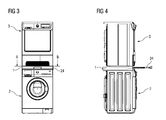
- shows a front view of the first appliance and of the second appliance after connection,
- FIG 4
- shows the corresponding side view of
FIG 3 , - FIG 5
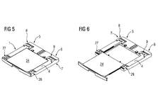
- shows a perspective view of a device according to the invention for connecting a first with a second appliance,
- FIG 6
- shows a perspective view of the device according to
FIG 5 with a panel element being drawn out from the device, - FIG 7
- shows a top view onto the device,
- FIG 8
- shows the detail "VIII" according to
FIG 7 , - FIG 9
- shows the top view onto a reception being part of the device to be brought into engagement with a foot of the second appliance,
- FIG 10
- shows the top view onto a reception according to
FIG 9 but according to the state or the art, - FIG 11
- shows the top view onto a reception according to
FIG 9 according to the invention, wherein the stem of the foot of the second appliance is in a first position, - FIG 12
- shows the top view onto a reception according to
FIG 9 and according to the invention, wherein the stem of the foot of the second appliance is in a second position, - FIG 13
- shows the section A-B according to
FIG 3 for a first kind of second appliance, - FIG 14
- shows the section A-B according to
FIG 3 for a second kind of second appliance, - FIG 15
- shows the section A-B according to
FIG 3 for a third kind of second appliance, - FIG 16
- shows the enlarged depiction according to
FIG 13 , - FIG 17
- shows the enlarged depiction according to
FIG 15 , - FIG 18
- shows a perspective view of the device for connecting the first with the second appliance with a fixation device for the fixation of the device on top of a first appliance and
- FIG 19
- shows a perspective view of a part of a first and a second appliance being connected by the device, seen from the rear.
- In
FIG 1 and FIG 2 afirst appliance 2, preferably being a washing machine, and asecond appliance 3, preferably being a dryer, are shown which has to be arranged one above the other in a stable manner. For doing so, adevice 1 for connecting is employed. The upper appliance, i.e. thesecond appliance 3, has fourfeet 10 which are arranged at stems which often are designed as a threaded rod. - While
FIG 1 and FIG 2 show the twoappliances FIG 3 and FIG 4 show theappliances device 1. Advantageously, thedevice 1 may comprise apanel element 24 which can be extracted from thedevice 1, as illustrated for example inFIG 4 and6 , so as to define a supporting plane or shelf adapted, for example, for holding a container of laundry before loading it into thehousehold appliance 2 positioned over thedevice 1. Advantageously, as illustrated inFIG 5 , thepanel element 24 may be pushed into a respective receiving space of thedevice 1, so as to reduce the encumbrance of thedevice 1 when thepanel element 24 is not used and to guarantee a convenient appearance of thedevice 1. - The
connection device 1 is depicted in the following figures, partially some details only. - In
FIG 5 and FIG 6 thedevice 1 is shown having advantageously basically aframe element 4. Theframe element 4 has preferably a substantial U-shaped form. So, a receivingspace 23 is formed for thepanel element 24 as mentioned above. The receivingspace 23 may be closed at its bottom - as in the embodiment illustrated - by a panel which connects the base and the arms of theU-shaped frame element 4. - The
device 1 has fourreceptions receptions 8, 9) and for the front feet of the upper appliance (receptions 27, 28). Consequently, thereceptions side regions device 1 and in arear region 7. Thereceptions side regions device 1. - The design of the
reception FIG 7 and FIG 8 . Eachreception carrier surface 12 on which a foot of thesecond appliance 3 can be placed. Thereception side walls FIG 8 . Thereception upper wall 16 in which arecess 17 is machined. Thus, thereception upper appliance 3 which is open at its front side. In this opening the foot is inserted during assembly. - The
receptions device 1 is connected to the latter), so that the feet of the upper appliance enters thereceptions - An essential design feature of the
recess 17 is that it has at least two adjacent sections 18, 19, each forming a housing or a dead stop for thestem 11 of the second (upper)appliance 3. - In the depicted embodiment the
recess 17 has advantageously a form defined by two adjacent concave lines 18 and 19 when seen in a top view. This becomes specifically apparent fromFIG 9 . The two concave lines 18, 19 are preferably circular arcs in the present case which, for example both extend along a circumferential extension of about a quarter circle. Consequently, the angle α, which is shown inFIG 9 , is about 90°. At the transition from one concave line 18 to the other concave line 19 preferably an apex 20 is formed. Furthermore, it can be seen that the two concave lines 18, 19 need not necessarily to be symmetrically. Specifically, thepoints 21 and 22 of the concave lines 18, 19 may have different distances "a" and "b" from the rear end of thedevice 1. - In spite of the given example according to above mentioned figures the design of the "concave lines" 18, 19 is to be understood in a wide interpretation. This comprises for example a design in which the shape of the concave lines is polygonal (for example lines 18 and 19 may be trapezoidal).
- In the present application the expression "concave lines" can generally being understood as a concave form (not necessarily curve, but also polygonal, or a combination thereof) which ensures a receiving of the
stem 11 as a housing or dead stop. Thus, the shape of the lines 18, 19 is adapted for partially housing thestem 11. The shown form of thelines 17, 18 is only a particular example. Of course, not only two but also more than two adjacent concave lines 18, 19 can be arranged. - In
FIG 9 the cross section of astem 11 which holds a foot of theupper appliance 3 is shown having a radius RS. It can be seen that this radius is preferably a bit smaller than the radius R of the concave lines 18, 19 (which in this case are advantageously circular arcs). - As can be seen from
FIG 7 and FIG 8 , beside the recess 17 asecond recess 25 can be arranged. Thissecond recess 17 can be of a pre-known type; in this case it has - as depicted - only on circular curved line, delimiting theupper wall 16. It can of course be of the kind as mentioned above, i.e. with two or more concave lines. - A
tongue 26 is advantageously extending between the tworecesses - The
second recess 25 allows the entry of a foot of an upper appliance into the reception having other dimensions, i.e. the distance between the two rear feet is different as in the case, when therecess 17 is used. - In
FIG 10, FIG 11 and FIG 12 the concept of the invention is illustrated again: - In
FIG 10 a pre-known solution (prior art) is shown. Therecess 17 has a semi-circular shape and thestem 11 is placed into thereception recess 17 must have a bigger width of its sides than the diameter of thestem 11, so that assembly is possible. Consequently, a movement between thereception stem 11 is possible detrimentally as illustrated by the arrow. - This is not the case when the solution according to the invention is employed as can be seen in
FIG 11 and inFIG 12 . Here thestem 11 has a substantially definite contact surface defined by the concave line 18 or the concave line 19. So, a movement in the direction of the arrow (as in the case ofFIG 10 ) is not possible. However, due to tolerances it is to be understood that very small movements are allowed. - In
FIG 13, FIG 14 and FIG 15 the section A-B according toFIG 3 is shown for three differentupper appliances 3 having stems 11 with different distances to another. Depending on the effective distance between the two stems 11 of the rear side of the appliance the final location in thereceptions - In
FIG 13 and FIG 15 the two concave lines 18 or 19 of therecess 17 are employed alternatively. InFIG 14 thesecond recess 25 is used by the stems 11. - From
FIG 13, FIG 14 and FIG 15 is can also be seen that the width of therecess 17 of thefront receptions receptions rear receptions - The same can be seen in
FIG 16 and FIG 17 which show enlarged depictions of the drawings accordingFIG 13 and FIG 15 . Here, also thefoot 10 is depicted which is pushed into the receiving chamber which is defined in areception - In
FIG 18 andFIG 19 it can be seen how thedevice 1 is fixed at atop plate 32 of thelower appliance 2. Thedevice 1 advantageously comprises afixation device 29 for firmly arrange thedevice 1 on thetop plate 32. The fixation device comprises a holdingelement 30 which has one ormore hook elements 31. Thehook elements 31 grab the bottom side of thetop plate 32 and are itself fixed at theframe element 4. The fixation takes place preferably by means of ascrew connection 33. - So, the
device 1 is firmly arranged on top of thetop plate 32 of thebottom appliance 2. - Consequently, a secure connection between the two
appliances - Even if the
fixation device 29 has been described with reference to thedevice 1, it is clear thatsuch fixation device 29 can be used also for other kinds of connection devices, even not provided with therecesses 17 according to the invention, provided that such connection devices are provided with a frame adapted to be fixed to thetop plate 32 of alower appliance 2. -
- 1
- Device for connecting
- 2
- First appliance (washing machine)
- 3
- Second appliance (dryer)
- 4
- Frame element
- 5
- Side region
- 6
- Side region
- 7
- Rear region
- 8
- Reception
- 9
- Reception
- 10
- Foot
- 11
- Stem
- 12
- Carrier surface
- 13
- Side wall
- 14
- Side wall
- 15
- Side wall
- 16
- Upper wall
- 17
- Recess
- 18
- Section (housing, dead stop), concave line
- 19
- Section (housing, dead stop), concave line
- 20
- Apex
- 21
- Point
- 22
- Point
- 23
- Receiving space
- 24
- Panel element
- 25
- Second recess
- 26
- Tongue
- 27
- Reception
- 28
- Reception
- 29
- Fixation device
- 30
- Holding element
- 31
- Hook element
- 32
- Top plate
- 33
- Screw connection
- α
- Angle
- R
- Radius
- RS
- Radius of stem
- a
- Distance
- b
- Distance
Claims (15)
- Device (1) for connecting a first appliance (2) with a second appliance (3), wherein the second appliance (3) is arranged on top of the first appliance (2),
wherein the device (1) comprises a frame element (4) which is designed to be fixed on top of the first appliance (2),
wherein the frame element (4) comprises at least two receptions (8, 9) for a foot (10) arranged at a stem (11) of the second appliance (3),
wherein each reception (8, 9) has a carrier surface (12) for the foot (10) which is limited by side walls (13, 14, 15) and an upper wall (16) having at least one recess (17) for the passage of the stem (11) of the foot (10),
characterized in that
at least one of the recesses (17) of the receptions (8, 9) has at least two adjacent sections (18, 19), each forming a housing or a dead stop for the stem (11) of the second appliance (3). - Device according to claim 1, characterized in that the recess (17) or at least one of the recesses (17) has a form defined by two adjacent concave lines (18, 19) seen in a top view.
- Device according to claim 1 or 2, characterized in that the frame element (4) has two side regions (5, 6) and a rear region (7), wherein the at least two receptions (8, 9) are arranged in the side regions (5, 6) of the frame element (4).
- Device according to claim 2 or 3, characterized in that the concave lines (18, 19) have the shape of a circular arc.
- Device according to claim 4, characterized in that each circular arc (18, 19) extends around an angle (α) between 60° and 120°.
- Device according to claim 4 or 5, characterized in that the radius (R) of the circular arc (18, 19) is between 100 % and 150 % of the radius (RS) of the stem (11) of the second appliance (3).
- Device according to one of claims 2 to 6, characterized in that an apex (20) is formed at the transition from one concave line (18) to the other concave line (19).
- Device according to one of claims 2 to 7, characterized in that the points (21, 22) of the concave lines (18, 19) being located closest to the rear end of the device (1) are arranged with different distances (a, b) to the rear end.
- Device according to one of claims 1 to 8, characterized in that the frame element (4) has a receiving space (23) for a panel element (24).
- Device according to one of claims 1 to 9, characterized in that a second recess (25) is formed into the upper wall (16) laterally to the recess (17).
- Device according to claim 10, characterized in that the upper wall (16) forms a tongue (26) between the recess (17) and the second recess (25) extending longitudinally in the direction from the front to the rear of the device (1).
- Device according to one of claims 1 to 11, characterized in that the receptions (8, 9) are arranged in the rear region (7) of the frame element (4) and/or in that further receptions (27, 28) are arranged in the front region of the frame element (4).
- Device according to one of claims 1 to 12, characterized in that is comprises a fixation device (29) for the fixation of the device (1) on the top side of the first appliance (2).
- Device according to claim 13, characterized in that the fixation device (29) comprises a holding element (30) having at least one hook element (31), wherein the hook element (31) is designed to be engaged with a top plate (32) of the first appliance (2).
- Device according to claim 13 or 14, characterized in that the holding element (30) is connected with the frame element (4) by means of a screw connection (33).
Priority Applications (1)
| Application Number | Priority Date | Filing Date | Title |
|---|---|---|---|
| EP10186360.3A EP2436819B1 (en) | 2010-10-04 | 2010-10-04 | Device for connecting a first appliance with a second appliance |
Applications Claiming Priority (1)
| Application Number | Priority Date | Filing Date | Title |
|---|---|---|---|
| EP10186360.3A EP2436819B1 (en) | 2010-10-04 | 2010-10-04 | Device for connecting a first appliance with a second appliance |
Publications (2)
| Publication Number | Publication Date |
|---|---|
| EP2436819A1 true EP2436819A1 (en) | 2012-04-04 |
| EP2436819B1 EP2436819B1 (en) | 2014-03-19 |
Family
ID=43770519
Family Applications (1)
| Application Number | Title | Priority Date | Filing Date |
|---|---|---|---|
| EP10186360.3A Not-in-force EP2436819B1 (en) | 2010-10-04 | 2010-10-04 | Device for connecting a first appliance with a second appliance |
Country Status (1)
| Country | Link |
|---|---|
| EP (1) | EP2436819B1 (en) |
Cited By (3)
| Publication number | Priority date | Publication date | Assignee | Title |
|---|---|---|---|---|
| EP2703536A1 (en) | 2012-08-31 | 2014-03-05 | Electrolux Home Products Corporation N.V. | Device for connecting a first appliance with a second appliance |
| WO2014101963A1 (en) * | 2012-12-30 | 2014-07-03 | Arcelik Anonim Sirketi | Laundry treatment appliance stacking apparatus |
| CN111350051A (en) * | 2018-12-21 | 2020-06-30 | 伊莱克斯家用电器股份公司 | Coupling structure for laundry treating apparatus |
Citations (5)
| Publication number | Priority date | Publication date | Assignee | Title |
|---|---|---|---|---|
| DE3329615A1 (en) * | 1983-08-17 | 1985-02-28 | Miele & Cie GmbH & Co, 4830 Gütersloh | Connection arrangement for household appliances which can be placed on top of one another |
| GB2221970A (en) * | 1988-08-16 | 1990-02-21 | Bosch Siemens Hausgeraete | Mounting one household appliance on top of another |
| EP1491676A2 (en) * | 2003-06-28 | 2004-12-29 | LG Electronics Inc. | Stand for home appliance |
| DE102005026134A1 (en) | 2005-06-06 | 2006-12-07 | BSH Bosch und Siemens Hausgeräte GmbH | Connection for domestic units, comprises a frame or board which can be fixed to the lower unit, and shoe sections for fixing the upper unit feet |
| WO2008084932A2 (en) * | 2007-01-10 | 2008-07-17 | Lg Electronics Inc. | Laundry device |
-
2010
- 2010-10-04 EP EP10186360.3A patent/EP2436819B1/en not_active Not-in-force
Patent Citations (5)
| Publication number | Priority date | Publication date | Assignee | Title |
|---|---|---|---|---|
| DE3329615A1 (en) * | 1983-08-17 | 1985-02-28 | Miele & Cie GmbH & Co, 4830 Gütersloh | Connection arrangement for household appliances which can be placed on top of one another |
| GB2221970A (en) * | 1988-08-16 | 1990-02-21 | Bosch Siemens Hausgeraete | Mounting one household appliance on top of another |
| EP1491676A2 (en) * | 2003-06-28 | 2004-12-29 | LG Electronics Inc. | Stand for home appliance |
| DE102005026134A1 (en) | 2005-06-06 | 2006-12-07 | BSH Bosch und Siemens Hausgeräte GmbH | Connection for domestic units, comprises a frame or board which can be fixed to the lower unit, and shoe sections for fixing the upper unit feet |
| WO2008084932A2 (en) * | 2007-01-10 | 2008-07-17 | Lg Electronics Inc. | Laundry device |
Cited By (4)
| Publication number | Priority date | Publication date | Assignee | Title |
|---|---|---|---|---|
| EP2703536A1 (en) | 2012-08-31 | 2014-03-05 | Electrolux Home Products Corporation N.V. | Device for connecting a first appliance with a second appliance |
| WO2014101963A1 (en) * | 2012-12-30 | 2014-07-03 | Arcelik Anonim Sirketi | Laundry treatment appliance stacking apparatus |
| CN111350051A (en) * | 2018-12-21 | 2020-06-30 | 伊莱克斯家用电器股份公司 | Coupling structure for laundry treating apparatus |
| CN111350051B (en) * | 2018-12-21 | 2024-01-09 | 伊莱克斯家用电器股份公司 | Coupling structure for laundry treating apparatus |
Also Published As
| Publication number | Publication date |
|---|---|
| EP2436819B1 (en) | 2014-03-19 |
Similar Documents
| Publication | Publication Date | Title |
|---|---|---|
| JP7194174B2 (en) | Storage shelf base and furniture or home appliance | |
| EP1747316B1 (en) | Drum assembly for washing machine | |
| KR102190635B1 (en) | Conductor terminal | |
| KR100845290B1 (en) | Drum Washing Machine | |
| EP2703536A1 (en) | Device for connecting a first appliance with a second appliance | |
| US10745848B2 (en) | Household appliance for washing | |
| EP3613325B1 (en) | Dishwasher | |
| KR20060005849A (en) | Home appliances with vertical fastening structure and fastening method | |
| CN104955370B (en) | Household electrical appliance | |
| EP2436819B1 (en) | Device for connecting a first appliance with a second appliance | |
| KR102139398B1 (en) | Case for cleaner | |
| EP2634304A1 (en) | Laundry machine with connector support | |
| CN105063971B (en) | For the housing unit and washing machine of washing machine | |
| CN203755865U (en) | Dish washing machine and hinge component thereof | |
| WO2017133782A1 (en) | Hinge assembly for use in a laundry treatment appliance | |
| EP2436820A1 (en) | Device for connecting a first appliance with a second appliance | |
| WO2011117767A1 (en) | Button push and pull mechanism | |
| WO2014161793A1 (en) | A household appliance comprising a lock | |
| US20060290247A1 (en) | Assembly structure of a washing machine's console and assembly method | |
| US20210123181A1 (en) | Door latch for a domestic electrical appliance and method for mounting such a door latch | |
| KR200439998Y1 (en) | Kitchen lighting fixtures | |
| EP2602575A2 (en) | Handle of a household appliance, in particular a refrigerating appliance | |
| WO2010049330A1 (en) | A washer/dryer | |
| EP3983597B1 (en) | A household appliance having a top plate | |
| WO2014118304A2 (en) | A support member for cooking devices and the cooking device wherein the same is used |
Legal Events
| Date | Code | Title | Description |
|---|---|---|---|
| PUAI | Public reference made under article 153(3) epc to a published international application that has entered the european phase |
Free format text: ORIGINAL CODE: 0009012 |
|
| AK | Designated contracting states |
Kind code of ref document: A1 Designated state(s): AL AT BE BG CH CY CZ DE DK EE ES FI FR GB GR HR HU IE IS IT LI LT LU LV MC MK MT NL NO PL PT RO RS SE SI SK SM TR |
|
| AX | Request for extension of the european patent |
Extension state: BA ME |
|
| 17P | Request for examination filed |
Effective date: 20121004 |
|
| 17Q | First examination report despatched |
Effective date: 20121026 |
|
| GRAP | Despatch of communication of intention to grant a patent |
Free format text: ORIGINAL CODE: EPIDOSNIGR1 |
|
| INTG | Intention to grant announced |
Effective date: 20131010 |
|
| GRAS | Grant fee paid |
Free format text: ORIGINAL CODE: EPIDOSNIGR3 |
|
| GRAA | (expected) grant |
Free format text: ORIGINAL CODE: 0009210 |
|
| AK | Designated contracting states |
Kind code of ref document: B1 Designated state(s): AL AT BE BG CH CY CZ DE DK EE ES FI FR GB GR HR HU IE IS IT LI LT LU LV MC MK MT NL NO PL PT RO RS SE SI SK SM TR |
|
| REG | Reference to a national code |
Ref country code: GB Ref legal event code: FG4D |
|
| REG | Reference to a national code |
Ref country code: CH Ref legal event code: EP |
|
| REG | Reference to a national code |
Ref country code: IE Ref legal event code: FG4D |
|
| REG | Reference to a national code |
Ref country code: AT Ref legal event code: REF Ref document number: 657768 Country of ref document: AT Kind code of ref document: T Effective date: 20140415 |
|
| REG | Reference to a national code |
Ref country code: DE Ref legal event code: R096 Ref document number: 602010014384 Country of ref document: DE Effective date: 20140430 |
|
| PG25 | Lapsed in a contracting state [announced via postgrant information from national office to epo] |
Ref country code: LT Free format text: LAPSE BECAUSE OF FAILURE TO SUBMIT A TRANSLATION OF THE DESCRIPTION OR TO PAY THE FEE WITHIN THE PRESCRIBED TIME-LIMIT Effective date: 20140319 Ref country code: NO Free format text: LAPSE BECAUSE OF FAILURE TO SUBMIT A TRANSLATION OF THE DESCRIPTION OR TO PAY THE FEE WITHIN THE PRESCRIBED TIME-LIMIT Effective date: 20140619 |
|
| REG | Reference to a national code |
Ref country code: NL Ref legal event code: VDEP Effective date: 20140319 |
|
| REG | Reference to a national code |
Ref country code: AT Ref legal event code: MK05 Ref document number: 657768 Country of ref document: AT Kind code of ref document: T Effective date: 20140319 |
|
| REG | Reference to a national code |
Ref country code: LT Ref legal event code: MG4D |
|
| PG25 | Lapsed in a contracting state [announced via postgrant information from national office to epo] |
Ref country code: FI Free format text: LAPSE BECAUSE OF FAILURE TO SUBMIT A TRANSLATION OF THE DESCRIPTION OR TO PAY THE FEE WITHIN THE PRESCRIBED TIME-LIMIT Effective date: 20140319 Ref country code: CY Free format text: LAPSE BECAUSE OF FAILURE TO SUBMIT A TRANSLATION OF THE DESCRIPTION OR TO PAY THE FEE WITHIN THE PRESCRIBED TIME-LIMIT Effective date: 20140319 Ref country code: SE Free format text: LAPSE BECAUSE OF FAILURE TO SUBMIT A TRANSLATION OF THE DESCRIPTION OR TO PAY THE FEE WITHIN THE PRESCRIBED TIME-LIMIT Effective date: 20140319 |
|
| PG25 | Lapsed in a contracting state [announced via postgrant information from national office to epo] |
Ref country code: HR Free format text: LAPSE BECAUSE OF FAILURE TO SUBMIT A TRANSLATION OF THE DESCRIPTION OR TO PAY THE FEE WITHIN THE PRESCRIBED TIME-LIMIT Effective date: 20140319 Ref country code: LV Free format text: LAPSE BECAUSE OF FAILURE TO SUBMIT A TRANSLATION OF THE DESCRIPTION OR TO PAY THE FEE WITHIN THE PRESCRIBED TIME-LIMIT Effective date: 20140319 Ref country code: RS Free format text: LAPSE BECAUSE OF FAILURE TO SUBMIT A TRANSLATION OF THE DESCRIPTION OR TO PAY THE FEE WITHIN THE PRESCRIBED TIME-LIMIT Effective date: 20140319 |
|
| PG25 | Lapsed in a contracting state [announced via postgrant information from national office to epo] |
Ref country code: EE Free format text: LAPSE BECAUSE OF FAILURE TO SUBMIT A TRANSLATION OF THE DESCRIPTION OR TO PAY THE FEE WITHIN THE PRESCRIBED TIME-LIMIT Effective date: 20140319 Ref country code: IS Free format text: LAPSE BECAUSE OF FAILURE TO SUBMIT A TRANSLATION OF THE DESCRIPTION OR TO PAY THE FEE WITHIN THE PRESCRIBED TIME-LIMIT Effective date: 20140719 Ref country code: BG Free format text: LAPSE BECAUSE OF FAILURE TO SUBMIT A TRANSLATION OF THE DESCRIPTION OR TO PAY THE FEE WITHIN THE PRESCRIBED TIME-LIMIT Effective date: 20140619 Ref country code: CZ Free format text: LAPSE BECAUSE OF FAILURE TO SUBMIT A TRANSLATION OF THE DESCRIPTION OR TO PAY THE FEE WITHIN THE PRESCRIBED TIME-LIMIT Effective date: 20140319 Ref country code: RO Free format text: LAPSE BECAUSE OF FAILURE TO SUBMIT A TRANSLATION OF THE DESCRIPTION OR TO PAY THE FEE WITHIN THE PRESCRIBED TIME-LIMIT Effective date: 20140319 Ref country code: BE Free format text: LAPSE BECAUSE OF FAILURE TO SUBMIT A TRANSLATION OF THE DESCRIPTION OR TO PAY THE FEE WITHIN THE PRESCRIBED TIME-LIMIT Effective date: 20140319 Ref country code: NL Free format text: LAPSE BECAUSE OF FAILURE TO SUBMIT A TRANSLATION OF THE DESCRIPTION OR TO PAY THE FEE WITHIN THE PRESCRIBED TIME-LIMIT Effective date: 20140319 |
|
| PG25 | Lapsed in a contracting state [announced via postgrant information from national office to epo] |
Ref country code: ES Free format text: LAPSE BECAUSE OF FAILURE TO SUBMIT A TRANSLATION OF THE DESCRIPTION OR TO PAY THE FEE WITHIN THE PRESCRIBED TIME-LIMIT Effective date: 20140319 Ref country code: AT Free format text: LAPSE BECAUSE OF FAILURE TO SUBMIT A TRANSLATION OF THE DESCRIPTION OR TO PAY THE FEE WITHIN THE PRESCRIBED TIME-LIMIT Effective date: 20140319 Ref country code: PL Free format text: LAPSE BECAUSE OF FAILURE TO SUBMIT A TRANSLATION OF THE DESCRIPTION OR TO PAY THE FEE WITHIN THE PRESCRIBED TIME-LIMIT Effective date: 20140319 Ref country code: SK Free format text: LAPSE BECAUSE OF FAILURE TO SUBMIT A TRANSLATION OF THE DESCRIPTION OR TO PAY THE FEE WITHIN THE PRESCRIBED TIME-LIMIT Effective date: 20140319 |
|
| REG | Reference to a national code |
Ref country code: DE Ref legal event code: R097 Ref document number: 602010014384 Country of ref document: DE |
|
| PG25 | Lapsed in a contracting state [announced via postgrant information from national office to epo] |
Ref country code: PT Free format text: LAPSE BECAUSE OF FAILURE TO SUBMIT A TRANSLATION OF THE DESCRIPTION OR TO PAY THE FEE WITHIN THE PRESCRIBED TIME-LIMIT Effective date: 20140721 |
|
| PLBE | No opposition filed within time limit |
Free format text: ORIGINAL CODE: 0009261 |
|
| STAA | Information on the status of an ep patent application or granted ep patent |
Free format text: STATUS: NO OPPOSITION FILED WITHIN TIME LIMIT |
|
| PG25 | Lapsed in a contracting state [announced via postgrant information from national office to epo] |
Ref country code: DK Free format text: LAPSE BECAUSE OF FAILURE TO SUBMIT A TRANSLATION OF THE DESCRIPTION OR TO PAY THE FEE WITHIN THE PRESCRIBED TIME-LIMIT Effective date: 20140319 |
|
| 26N | No opposition filed |
Effective date: 20141222 |
|
| PG25 | Lapsed in a contracting state [announced via postgrant information from national office to epo] |
Ref country code: IT Free format text: LAPSE BECAUSE OF FAILURE TO SUBMIT A TRANSLATION OF THE DESCRIPTION OR TO PAY THE FEE WITHIN THE PRESCRIBED TIME-LIMIT Effective date: 20140319 |
|
| REG | Reference to a national code |
Ref country code: DE Ref legal event code: R097 Ref document number: 602010014384 Country of ref document: DE Effective date: 20141222 |
|
| REG | Reference to a national code |
Ref country code: DE Ref legal event code: R119 Ref document number: 602010014384 Country of ref document: DE |
|
| PG25 | Lapsed in a contracting state [announced via postgrant information from national office to epo] |
Ref country code: MC Free format text: LAPSE BECAUSE OF FAILURE TO SUBMIT A TRANSLATION OF THE DESCRIPTION OR TO PAY THE FEE WITHIN THE PRESCRIBED TIME-LIMIT Effective date: 20140319 Ref country code: LU Free format text: LAPSE BECAUSE OF FAILURE TO SUBMIT A TRANSLATION OF THE DESCRIPTION OR TO PAY THE FEE WITHIN THE PRESCRIBED TIME-LIMIT Effective date: 20141004 |
|
| REG | Reference to a national code |
Ref country code: CH Ref legal event code: PL |
|
| GBPC | Gb: european patent ceased through non-payment of renewal fee |
Effective date: 20141004 |
|
| REG | Reference to a national code |
Ref country code: IE Ref legal event code: MM4A |
|
| PG25 | Lapsed in a contracting state [announced via postgrant information from national office to epo] |
Ref country code: SI Free format text: LAPSE BECAUSE OF FAILURE TO SUBMIT A TRANSLATION OF THE DESCRIPTION OR TO PAY THE FEE WITHIN THE PRESCRIBED TIME-LIMIT Effective date: 20140319 Ref country code: CH Free format text: LAPSE BECAUSE OF NON-PAYMENT OF DUE FEES Effective date: 20141031 Ref country code: GB Free format text: LAPSE BECAUSE OF NON-PAYMENT OF DUE FEES Effective date: 20141004 Ref country code: DE Free format text: LAPSE BECAUSE OF NON-PAYMENT OF DUE FEES Effective date: 20150501 Ref country code: LI Free format text: LAPSE BECAUSE OF NON-PAYMENT OF DUE FEES Effective date: 20141031 |
|
| REG | Reference to a national code |
Ref country code: FR Ref legal event code: ST Effective date: 20150630 |
|
| PG25 | Lapsed in a contracting state [announced via postgrant information from national office to epo] |
Ref country code: FR Free format text: LAPSE BECAUSE OF NON-PAYMENT OF DUE FEES Effective date: 20141031 |
|
| PG25 | Lapsed in a contracting state [announced via postgrant information from national office to epo] |
Ref country code: IE Free format text: LAPSE BECAUSE OF NON-PAYMENT OF DUE FEES Effective date: 20141004 |
|
| PG25 | Lapsed in a contracting state [announced via postgrant information from national office to epo] |
Ref country code: SM Free format text: LAPSE BECAUSE OF FAILURE TO SUBMIT A TRANSLATION OF THE DESCRIPTION OR TO PAY THE FEE WITHIN THE PRESCRIBED TIME-LIMIT Effective date: 20140319 |
|
| PG25 | Lapsed in a contracting state [announced via postgrant information from national office to epo] |
Ref country code: GR Free format text: LAPSE BECAUSE OF FAILURE TO SUBMIT A TRANSLATION OF THE DESCRIPTION OR TO PAY THE FEE WITHIN THE PRESCRIBED TIME-LIMIT Effective date: 20140620 |
|
| PG25 | Lapsed in a contracting state [announced via postgrant information from national office to epo] |
Ref country code: MT Free format text: LAPSE BECAUSE OF FAILURE TO SUBMIT A TRANSLATION OF THE DESCRIPTION OR TO PAY THE FEE WITHIN THE PRESCRIBED TIME-LIMIT Effective date: 20140319 Ref country code: HU Free format text: LAPSE BECAUSE OF FAILURE TO SUBMIT A TRANSLATION OF THE DESCRIPTION OR TO PAY THE FEE WITHIN THE PRESCRIBED TIME-LIMIT; INVALID AB INITIO Effective date: 20101004 Ref country code: TR Free format text: LAPSE BECAUSE OF FAILURE TO SUBMIT A TRANSLATION OF THE DESCRIPTION OR TO PAY THE FEE WITHIN THE PRESCRIBED TIME-LIMIT Effective date: 20140319 |
|
| PG25 | Lapsed in a contracting state [announced via postgrant information from national office to epo] |
Ref country code: MK Free format text: LAPSE BECAUSE OF FAILURE TO SUBMIT A TRANSLATION OF THE DESCRIPTION OR TO PAY THE FEE WITHIN THE PRESCRIBED TIME-LIMIT Effective date: 20140319 |
|
| PG25 | Lapsed in a contracting state [announced via postgrant information from national office to epo] |
Ref country code: AL Free format text: LAPSE BECAUSE OF FAILURE TO SUBMIT A TRANSLATION OF THE DESCRIPTION OR TO PAY THE FEE WITHIN THE PRESCRIBED TIME-LIMIT Effective date: 20140319 |