EP2436407A1 - Syringe assembly carrier - Google Patents
Syringe assembly carrier Download PDFInfo
- Publication number
- EP2436407A1 EP2436407A1 EP11007638A EP11007638A EP2436407A1 EP 2436407 A1 EP2436407 A1 EP 2436407A1 EP 11007638 A EP11007638 A EP 11007638A EP 11007638 A EP11007638 A EP 11007638A EP 2436407 A1 EP2436407 A1 EP 2436407A1
- Authority
- EP
- European Patent Office
- Prior art keywords
- syringe
- syringe assembly
- well
- assembly carrier
- receive
- Prior art date
- Legal status (The legal status is an assumption and is not a legal conclusion. Google has not performed a legal analysis and makes no representation as to the accuracy of the status listed.)
- Granted
Links
Images


Classifications
-
- A—HUMAN NECESSITIES
- A61—MEDICAL OR VETERINARY SCIENCE; HYGIENE
- A61M—DEVICES FOR INTRODUCING MEDIA INTO, OR ONTO, THE BODY; DEVICES FOR TRANSDUCING BODY MEDIA OR FOR TAKING MEDIA FROM THE BODY; DEVICES FOR PRODUCING OR ENDING SLEEP OR STUPOR
- A61M5/00—Devices for bringing media into the body in a subcutaneous, intra-vascular or intramuscular way; Accessories therefor, e.g. filling or cleaning devices, arm rests
- A61M5/008—Racks for supporting syringes or needles
Definitions
- the present disclosure relates to syringes and, more particularly, to medical syringe assemblies such as disposable syringes and prefilled syringes, which include a selectively attachable/detachable plunger rod, and syringe assembly carriers suitable for syringe filling and distribution of syringe assemblies.
- medical syringe assemblies such as disposable syringes and prefilled syringes, which include a selectively attachable/detachable plunger rod, and syringe assembly carriers suitable for syringe filling and distribution of syringe assemblies.
- a conventional syringe typically includes a hollow barrel configured to slideably receive a plunger having a piston supported on a distal end thereof.
- the plunger is received in the hollow barrel and partially extends through a proximal end thereof.
- the piston is also translated to thereby aspirate and/or dispense fluid into/out of the hollow barrel.
- Syringes have been developed for use as disposable syringes that are discarded after a single administration and which include a selectively attachable/detachable plunger assembly.
- a single-use syringe prevents reuse of the syringe to minimize exposure of patients to HIV, hepatitis and other blood-borne pathogens.
- the syringe is provided with a barrel containing a fluid and with the plunger pre-attached to the barrel.
- the portion of the plunger extending from the barrel may be relatively large.
- pre-filled syringes have been developed wherein the plunger is selectively attachable/detachable to/from the piston. In this manner, syringes including pre-filled barrels and separate plungers may be stored and shipped at reduced costs.
- the present disclosure relates to a syringe assembly carrier including a syringe-well holding fixture, a plurality of openings defined in the syringe-well holding fixture, and a plurality of syringe wells.
- Each of the syringe wells is configured to removeably receive a syringe assembly.
- the syringe-well holding fixture includes an upper surface and a plurality of annular mounting flanges coupled to the upper surface.
- Each of the plurality of annular mounting flanges is individually associated with a different opening in the syringe-well holding fixture and configured to receive a syringe well.
- FIG. 1 is a perspective view of a syringe assembly carrier with parts separated according to an embodiment of the present disclosure
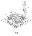
- FIG. 2 is a perspective view of an embodiment of a syringe assembly with parts separated and an embodiment of an opaque, syringe-well holding fixture shown in a partially-filled configuration with syringe assemblies (in phantom lines) disposed in transparent syringe wells in accordance with the present disclosure; and
- FIG. 3 is a perspective view of a syringe assembly as shown in FIG. 2 and an embodiment of a transparent, syringe-well holding fixture shown in a substantially-filled configuration with syringe assemblies (in phantom lines) disposed in transparent syringe wells according to an embodiment of the present disclosure.
- proximal refers to that portion of the apparatus, or component thereof, closer to the user and the term “distal” refers to that portion of the apparatus, or component thereof, farther from the user.
- Embodiments of the presently-disclosed syringe assembly are suitable for use as disposable syringes and prefilled syringes.
- Embodiments of the presently-disclosed syringe assembly carrier allow syringes to be assembled, sterilized and distributed in a structured configuration suitable for presentation to automated syringe-filling operations.
- the teachings of the present disclosure may apply to a variety of syringe assemblies that include a selectively attachable/detachable plunger assembly.
- FIG.1 illustrates one embodiment of the presently-disclosed syringe assembly carrier shown generally as 110.
- Syringe assembly carrier 110 includes a plurality of syringe wells 1, a syringe-well holding fixture 10, an array of openings 15 defined in syringe-well holding fixture 10, and a plurality of annular mounting flanges 13 individually associated with openings 15 and configured to receive syringe wells 1.
- each of the annular mounting flanges 13 is configured to releaseably or semi-permanently receive a syringe well 1.
- each of the annular mounting flanges 13 is configured to permanently receive a syringe well 1.
- Each of the plurality of syringe wells 1 includes an interior cavity 48 of sufficient diameter to removeably receive a syringe assembly (e.g., 100 shown in FIGS. 2 and 3 ).
- a plurality of sealing caps 53 may be provided for assembly with the syringe wells 1.
- the plurality of openings 15 and the annular mounting flanges 13 are generally arranged in a pattern of rows and/or columns. Alternatively, other patterns are envisioned. Openings 15 and the annular mounting flanges 13 may be arranged as nested rows and columns. Openings 15 may be arranged in a series of rows and/or columns, and may be uniformly spaced apart.
- the syringe-well holding fixture 10 and annular mounting flanges 13 may be integrally formed as a unitary structure. The number, shape and size of the openings 15 and the annular mounting flanges 13 may be varied from the configuration depicted in FIGS. 1 through 3 . Openings 15 may have any configuration suitable for a specific purpose. For example, openings 15 may be shaped as circles, square, triangles, octagons and the like.
- Syringe-well holding fixture 10 and the syringe wells 1 may be separately formed by injection-molding devices from suitable polymeric materials, e.g., polyolefins such as polypropylene.
- suitable polymeric materials e.g., polyolefins such as polypropylene.
- one or more syringe wells 1 and/or the syringe-well holding fixture 10 may be transparent or semi-transparent, which mayallow a user to visually inspect the syringe assemblies 100 disposed within the syringe wells 1.
- one or more syringe wells 1 and/or the syringe-well holding fixture 10 may be opaque, e.g., to protect the contents of the syringe wells 1 against exposure to light.
- each of the syringe wells 1 is transparent and the syringe-well holding fixture 10 is opaque.
- each of the syringe wells 1 and the syringe-well holding fixture 10 is transparent. It is contemplated and within the scope of the present disclosure that the presently-disclosed syringe-well holding fixture 10 may be provided with various configurations of opaque syringe wells 1 and/or transparent syringe wells 1, which may accommodate filled and/or unfilled syringe assemblies therein.
- Syringe-well holding fixture 10 includes an upper surface 11, which may be flat or substantially flat, and a lower surface 12.
- the fixture 10 has a generally rectangular shape, which may be formed from a first side "S1", a second side “S2", a third side “S3” and a fourth side "S4". It is also envisioned that the fixture may assume other configurations, e.g., circular, square, etc. As shown in FIG. 2 , the first side "S1" and the second side “S2" have a suitable length "L1", and the third side “S3" and the fourth side "S4" have a suitable length "L2".
- first side "S1" and the second side “S2” are disposed perpendicular to the third side "S3" and the fourth side "S4".
- Syringe-well holding fixture 10 may be fabricated from a suitably rigid material.
- the fixture 10 is formed substantially or entirely from a polymeric material, e.g., plastic.
- one or more cut-out portions 16 are defined in the syringe-well holding fixture 10, e.g., to facilitate gripping the syringe assembly carrier 110 and/or to allow the fixture 10 to be positionable in a predetermined orientation for syringe filling operations.
- fixture 10 includes two cut-out portions 16 disposed on opposite sides of the fixture 10, e.g., the third side "S3" and the fourth side "S4".
- Syringe assembly carrier 110 may include one or more rib elements 17 ( FIG. 1 ), which may be disposed in proximity to the one or more cut-out portions 16 and configured to provide structural support and rigidity to the syringe-well holding fixture 10.
- Rib elements 17 may be coupled to the upper surface 11 of the fixture 10 and/or the lower surface 12 of the fixture 10.
- the syringe-well holding fixture 10 includes two cut-out portions 16 and two rib elements 17 coupled to the upper surface 11, wherein each rib element 17 has a generally U-like shape and is disposed in proximity to a corresponding one of the cut-out portions 16.
- the number, size, shape and relative spacing of the cut-out portions 16 and rib elements 17 may be varied from the configuration depicted in FIG. 1 .
- each of the plurality of syringe wells 1 includes an open end 3, a closed end 2, and a sleeve body 40, wherein an interior cavity 48 is defined within the sleeve body 40 between the open end 3 and the closed end 2.
- Sleeve body 40 may include a first portion 41, e.g., a lower portion, having a generally cylindrical configuration, and a second portion 42, e.g., an upper portion.
- Sleeve body 40 may be configured to press-fit, snap, or otherwise seal into the annular mounting flanges 13 of syringe-well holding fixture 10.
- the sleeve body 40 is releaseably or semi-permanently coupleable to the annular mounting flanges 13.
- the sleeve body 40 is permanently coupleable to the annular mounting flanges 13.
- the second portion 42 of the sleeve body 40 may be configured to receive a sealing cap 53.
- the closed end 2 of the syringe wells 1 may have a rounded shape, or other suitable shape, such as triangular, square, octagon and the like.
- the sleeve body 42 may have differing cross sectional areas along its length. For example the cross sectional area of the upper portion 42 of the sleeve may be larger than the cross sectional area of the lower portion 41 of the sleeve.
- FIG. 2 illustrates one embodiment of the presently-disclosed syringe assembly shown generally as 100 and an embodiment of syringe assembly carrier 110.
- the syringe-well holding fixture 10 is opaque and each of the plurality of syringe wells 1 is transparent.
- Syringe assembly 100 may be a single-use assembly, which is disposable after use on a subject. Syringe assembly 100 is suitable for use in pre-filled applications and includes a syringe body 32, a flange 22, and a tip cap 46. Syringe body 32 defines a fluid chamber or reservoir 38 and includes a distally-positioned nozzle portion or tip 39, which is disposed in fluid communication with the fluid reservoir 38. Tip cap 46 includes an open end configured to be releaseably coupleable with the distal end of the nozzle portion or tip 39.
- the syringe body 32 is made of plastic, e.g., transparent polypropylene. Syringe body 32 may be constructed of nearly any polymeric or glass material.
- a plunger assembly (not shown) may be provided for assembly with the syringe body 32.
- Fluid reservoir 38 is generally configured to contain a material to be dispensed and/or aspirated.
- the fluid reservoir 38 may have an internal volume of about 0.3 ml (milliliters) to about 100 ml, although other fluid reservoir volumes are envisioned.
- a peripheral flange 22 Adjacent the proximal end of the syringe body 32 is a peripheral flange 22 that includes a proximal end 21 and extends perpendicularly beyond the periphery of the syringe body 32.
- Syringe flange 22 may be integrally formed with the syringe body 32.
- FIG. 3 a plurality of the syringe assemblies 100 are shown (in phantom lines) disposed within syringe wells 1, wherein each of the syringe wells 1 is provided with a sealing cap 53 and is coupled to the syringe-well holding fixture 10 of the syringe assembly carrier 110.
- Syringe assemblies 100 are oriented generally perpendicularly to the generally planar upper surface 11 of the syringe-well holding fixture 10 and are loaded into the syringe-well holding fixture 10 such that the distal end of the syringe body 32, covered by the tip cap 46, faces the closed end 2 of the syringe well 1 and the proximal end 21 of the syringe flange 22 faces upward.
- fluid reservoir 38 of the syringe assembly 100 is filled with a solution (not shown) before the syringe assembly 100 is loaded into a syringe well 1 of the syringe assembly carrier 110.
- the syringe assembly 100 is loaded into a syringe well 1 before the fluid reservoir 38 is filled with a solution.
- syringe assembly 100 may contain a flushing solution, e.g., saline or the like.
- syringe assembly 100 may contain medicinals, including antibiotics, pain medication, therapeutic drugs, heparin or the like.
- Sealing caps 53 may be applied to the syringe wells 1 after the syringe assemblies 100 are loaded into the syringe well 1, sterilized, and/or filled with a solution. Sealing caps 53 are configured to be releaseably coupleable to the upper portion 42 of syringe wells 1 by any suitable manner of releasable connection, such as, snap-fit, press-fit, screw-fit, bayonet-fit, friction-fit, releasable adhesive, or other releasable configuration.
- a sterile barrier film (not shown) may be provided, wherein the barrier film is configured to cover the open ends 3 of the syringe wells 1.
- the barrier film may be adhered by an adhesive layer (not shown), or other suitable manner of adhesion, welding or the like.
- the barrier film may be applied to cover the open ends 3 of the syringe wells 1 after the syringe assemblies 100 are loaded into the syringes well 1, sterilized, and/or filled with a solution.
Landscapes
- Health & Medical Sciences (AREA)
- Vascular Medicine (AREA)
- Engineering & Computer Science (AREA)
- Anesthesiology (AREA)
- Biomedical Technology (AREA)
- Heart & Thoracic Surgery (AREA)
- Hematology (AREA)
- Life Sciences & Earth Sciences (AREA)
- Animal Behavior & Ethology (AREA)
- General Health & Medical Sciences (AREA)
- Public Health (AREA)
- Veterinary Medicine (AREA)
- Infusion, Injection, And Reservoir Apparatuses (AREA)
- Apparatus Associated With Microorganisms And Enzymes (AREA)
Abstract
Description
- The present disclosure relates to syringes and, more particularly, to medical syringe assemblies such as disposable syringes and prefilled syringes, which include a selectively attachable/detachable plunger rod, and syringe assembly carriers suitable for syringe filling and distribution of syringe assemblies.
- A conventional syringe typically includes a hollow barrel configured to slideably receive a plunger having a piston supported on a distal end thereof. The plunger is received in the hollow barrel and partially extends through a proximal end thereof. In use, as the plunger is translated relative to the hollow barrel, the piston is also translated to thereby aspirate and/or dispense fluid into/out of the hollow barrel.
- Syringes have been developed for use as disposable syringes that are discarded after a single administration and which include a selectively attachable/detachable plunger assembly. A single-use syringe prevents reuse of the syringe to minimize exposure of patients to HIV, hepatitis and other blood-borne pathogens.
- In the case of pre-filled syringes, the syringe is provided with a barrel containing a fluid and with the plunger pre-attached to the barrel. In the instance of relatively large pre-filled syringes, the portion of the plunger extending from the barrel may be relatively large. To reduce the overall length of the pre-filled barrel and plunger, pre-filled syringes have been developed wherein the plunger is selectively attachable/detachable to/from the piston. In this manner, syringes including pre-filled barrels and separate plungers may be stored and shipped at reduced costs.
- A need exists for an improved syringe assembly carrier which provides a structured configuration to simplify sterilization, distribution and presentation of the syringe assemblies to automated syringe-filling operations.
- The present disclosure relates to a syringe assembly carrier including a syringe-well holding fixture, a plurality of openings defined in the syringe-well holding fixture, and a plurality of syringe wells. Each of the syringe wells is configured to removeably receive a syringe assembly. The syringe-well holding fixture includes an upper surface and a plurality of annular mounting flanges coupled to the upper surface. Each of the plurality of annular mounting flanges is individually associated with a different opening in the syringe-well holding fixture and configured to receive a syringe well.
- Objects and features of the presently-disclosed syringe assemblies and syringe assembly carriers suitable for syringe filling and distribution of syringe assemblies will become apparent to those of ordinary skill in the art when descriptions of various embodiments thereof are read with reference to the accompanying drawings, of which:
-
FIG. 1 is a perspective view of a syringe assembly carrier with parts separated according to an embodiment of the present disclosure; -
FIG. 2 is a perspective view of an embodiment of a syringe assembly with parts separated and an embodiment of an opaque, syringe-well holding fixture shown in a partially-filled configuration with syringe assemblies (in phantom lines) disposed in transparent syringe wells in accordance with the present disclosure; and -
FIG. 3 is a perspective view of a syringe assembly as shown inFIG. 2 and an embodiment of a transparent, syringe-well holding fixture shown in a substantially-filled configuration with syringe assemblies (in phantom lines) disposed in transparent syringe wells according to an embodiment of the present disclosure. - Hereinafter, embodiments of a syringe assembly and a syringe assembly carrier suitable for syringe filling and distribution of syringe assemblies are described with reference to the accompanying drawings. Like reference numerals may refer to similar or identical elements throughout the description of the figures. As shown in the drawings and as used in this description, and as is traditional when referring to relative positioning on an object, the term "proximal" refers to that portion of the apparatus, or component thereof, closer to the user and the term "distal" refers to that portion of the apparatus, or component thereof, farther from the user.
- This description may use the phrases "in an embodiment," "in embodiments," "in some embodiments," or "in other embodiments," which may each refer to one or more of the same or different embodiments in accordance with the present disclosure. For the purposes of this description, a phrase in the form "A/B" means A or B. For the purposes of the description, a phrase in the form "A and/or B" means "(A), (B), or (A and B)". As it is used in this description, "plastic" generally refers to any of a wide variety of resins or polymers with different characteristics and uses.
- Embodiments of the presently-disclosed syringe assembly are suitable for use as disposable syringes and prefilled syringes. Embodiments of the presently-disclosed syringe assembly carrier allow syringes to be assembled, sterilized and distributed in a structured configuration suitable for presentation to automated syringe-filling operations. The teachings of the present disclosure may apply to a variety of syringe assemblies that include a selectively attachable/detachable plunger assembly.
-
FIG.1 illustrates one embodiment of the presently-disclosed syringe assembly carrier shown generally as 110.Syringe assembly carrier 110 includes a plurality ofsyringe wells 1, a syringe-well holdingfixture 10, an array ofopenings 15 defined in syringe-well holdingfixture 10, and a plurality ofannular mounting flanges 13 individually associated withopenings 15 and configured to receivesyringe wells 1. In some embodiments, each of theannular mounting flanges 13 is configured to releaseably or semi-permanently receive a syringe well 1. In some embodiments, each of theannular mounting flanges 13 is configured to permanently receive a syringe well 1. Each of the plurality ofsyringe wells 1 includes aninterior cavity 48 of sufficient diameter to removeably receive a syringe assembly (e.g., 100 shown inFIGS. 2 and3 ). A plurality ofsealing caps 53 may be provided for assembly with thesyringe wells 1. - The plurality of
openings 15 and theannular mounting flanges 13 are generally arranged in a pattern of rows and/or columns. Alternatively, other patterns are envisioned.Openings 15 and theannular mounting flanges 13 may be arranged as nested rows and columns.Openings 15 may be arranged in a series of rows and/or columns, and may be uniformly spaced apart. The syringe-well holdingfixture 10 andannular mounting flanges 13 may be integrally formed as a unitary structure. The number, shape and size of theopenings 15 and theannular mounting flanges 13 may be varied from the configuration depicted inFIGS. 1 through 3 .Openings 15 may have any configuration suitable for a specific purpose. For example,openings 15 may be shaped as circles, square, triangles, octagons and the like. - Syringe-well holding
fixture 10 and thesyringe wells 1 may be separately formed by injection-molding devices from suitable polymeric materials, e.g., polyolefins such as polypropylene. In some embodiments, one ormore syringe wells 1 and/or the syringe-well holdingfixture 10 may be transparent or semi-transparent, which mayallow a user to visually inspect thesyringe assemblies 100 disposed within thesyringe wells 1. Alternatively, one ormore syringe wells 1 and/or the syringe-well holdingfixture 10 may be opaque, e.g., to protect the contents of thesyringe wells 1 against exposure to light. - In the embodiment illustrated in
FIG. 2 , each of thesyringe wells 1 is transparent and the syringe-well holdingfixture 10 is opaque. In the embodiment illustrated inFIG. 3 , each of thesyringe wells 1 and the syringe-well holdingfixture 10 is transparent. It is contemplated and within the scope of the present disclosure that the presently-disclosed syringe-well holdingfixture 10 may be provided with various configurations ofopaque syringe wells 1 and/ortransparent syringe wells 1, which may accommodate filled and/or unfilled syringe assemblies therein. - Syringe-well holding
fixture 10 includes anupper surface 11, which may be flat or substantially flat, and alower surface 12. In some embodiments, thefixture 10 has a generally rectangular shape, which may be formed from a first side "S1", a second side "S2", a third side "S3" and a fourth side "S4". It is also envisioned that the fixture may assume other configurations, e.g., circular, square, etc. As shown inFIG. 2 , the first side "S1" and the second side "S2" have a suitable length "L1", and the third side "S3" and the fourth side "S4" have a suitable length "L2". In some embodiments, the first side "S1" and the second side "S2" are disposed perpendicular to the third side "S3" and the fourth side "S4". Syringe-well holdingfixture 10 may be fabricated from a suitably rigid material. In some embodiments, thefixture 10 is formed substantially or entirely from a polymeric material, e.g., plastic. - In some embodiments, one or more cut-out portions 16 (
FIG. 1 ) are defined in the syringe-well holdingfixture 10, e.g., to facilitate gripping thesyringe assembly carrier 110 and/or to allow thefixture 10 to be positionable in a predetermined orientation for syringe filling operations. In one embodiment,fixture 10 includes two cut-outportions 16 disposed on opposite sides of thefixture 10, e.g., the third side "S3" and the fourth side "S4".Syringe assembly carrier 110 may include one or more rib elements 17 (FIG. 1 ), which may be disposed in proximity to the one or more cut-outportions 16 and configured to provide structural support and rigidity to the syringe-well holdingfixture 10.Rib elements 17 may be coupled to theupper surface 11 of thefixture 10 and/or thelower surface 12 of thefixture 10. In the embodiment illustrated inFIGS. 1 through 3 , the syringe-well holdingfixture 10 includes two cut-outportions 16 and tworib elements 17 coupled to theupper surface 11, wherein eachrib element 17 has a generally U-like shape and is disposed in proximity to a corresponding one of the cut-outportions 16. The number, size, shape and relative spacing of the cut-outportions 16 andrib elements 17 may be varied from the configuration depicted inFIG. 1 . - Referring again to
FIG. 1 , each of the plurality ofsyringe wells 1 includes an open end 3, aclosed end 2, and asleeve body 40, wherein aninterior cavity 48 is defined within thesleeve body 40 between the open end 3 and theclosed end 2.Sleeve body 40 may include afirst portion 41, e.g., a lower portion, having a generally cylindrical configuration, and asecond portion 42, e.g., an upper portion.Sleeve body 40 may be configured to press-fit, snap, or otherwise seal into theannular mounting flanges 13 of syringe-well holdingfixture 10. In some embodiments, thesleeve body 40 is releaseably or semi-permanently coupleable to the annular mountingflanges 13. In other embodiments, thesleeve body 40 is permanently coupleable to the annular mountingflanges 13. Thesecond portion 42 of thesleeve body 40 may be configured to receive a sealingcap 53. Theclosed end 2 of thesyringe wells 1 may have a rounded shape, or other suitable shape, such as triangular, square, octagon and the like. In some embodiment thesleeve body 42 may have differing cross sectional areas along its length. For example the cross sectional area of theupper portion 42 of the sleeve may be larger than the cross sectional area of thelower portion 41 of the sleeve. -
FIG. 2 illustrates one embodiment of the presently-disclosed syringe assembly shown generally as 100 and an embodiment ofsyringe assembly carrier 110. In the embodiment illustrated inFIG. 2 , the syringe-well holdingfixture 10 is opaque and each of the plurality ofsyringe wells 1 is transparent. -
Syringe assembly 100 may be a single-use assembly, which is disposable after use on a subject.Syringe assembly 100 is suitable for use in pre-filled applications and includes asyringe body 32, aflange 22, and atip cap 46.Syringe body 32 defines a fluid chamber orreservoir 38 and includes a distally-positioned nozzle portion ortip 39, which is disposed in fluid communication with thefluid reservoir 38.Tip cap 46 includes an open end configured to be releaseably coupleable with the distal end of the nozzle portion ortip 39. In some embodiments, thesyringe body 32 is made of plastic, e.g., transparent polypropylene.Syringe body 32 may be constructed of nearly any polymeric or glass material. A plunger assembly (not shown) may be provided for assembly with thesyringe body 32. -
Fluid reservoir 38 is generally configured to contain a material to be dispensed and/or aspirated. In embodiments, thefluid reservoir 38 may have an internal volume of about 0.3 ml (milliliters) to about 100 ml, although other fluid reservoir volumes are envisioned. - Adjacent the proximal end of the
syringe body 32 is aperipheral flange 22 that includes aproximal end 21 and extends perpendicularly beyond the periphery of thesyringe body 32.Syringe flange 22 may be integrally formed with thesyringe body 32. - In
FIG. 3 , a plurality of thesyringe assemblies 100 are shown (in phantom lines) disposed withinsyringe wells 1, wherein each of thesyringe wells 1 is provided with a sealingcap 53 and is coupled to the syringe-well holdingfixture 10 of thesyringe assembly carrier 110.Syringe assemblies 100 are oriented generally perpendicularly to the generally planarupper surface 11 of the syringe-well holdingfixture 10 and are loaded into the syringe-well holdingfixture 10 such that the distal end of thesyringe body 32, covered by thetip cap 46, faces theclosed end 2 of the syringe well 1 and theproximal end 21 of thesyringe flange 22 faces upward. - In some embodiments,
fluid reservoir 38 of thesyringe assembly 100 is filled with a solution (not shown) before thesyringe assembly 100 is loaded into a syringe well 1 of thesyringe assembly carrier 110. In other embodiments, thesyringe assembly 100 is loaded into a syringe well 1 before thefluid reservoir 38 is filled with a solution. In certain applications,syringe assembly 100 may contain a flushing solution, e.g., saline or the like. Alternatively,syringe assembly 100 may contain medicinals, including antibiotics, pain medication, therapeutic drugs, heparin or the like. - Sealing caps 53 may be applied to the
syringe wells 1 after thesyringe assemblies 100 are loaded into the syringe well 1, sterilized, and/or filled with a solution. Sealing caps 53 are configured to be releaseably coupleable to theupper portion 42 ofsyringe wells 1 by any suitable manner of releasable connection, such as, snap-fit, press-fit, screw-fit, bayonet-fit, friction-fit, releasable adhesive, or other releasable configuration. - In some embodimentsin which sealing caps are not utilized, a sterile barrier film (not shown) may be provided, wherein the barrier film is configured to cover the open ends 3 of the
syringe wells 1. The barrier film may be adhered by an adhesive layer (not shown), or other suitable manner of adhesion, welding or the like. The barrier film may be applied to cover the open ends 3 of thesyringe wells 1 after thesyringe assemblies 100 are loaded into the syringes well 1, sterilized, and/or filled with a solution. - Although embodiments have been described in detail with reference to the accompanying drawings for the purpose of illustration and description, it is to be understood that the inventive processes and apparatus are not to be construed as limited thereby. It will be apparent to those of ordinary skill in the art that various modifications to the foregoing embodiments may be made without departing from the scope of the disclosure.
Claims (11)
- A syringe assembly carrier, comprising:a plurality of syringe wells, each configured to removeably receive a syringe assembly;a syringe-well holding fixture including an upper surface;a plurality of openings defined in the syringe-well holding fixture; anda plurality of annular mounting flanges coupled to the upper surface, wherein each of the plurality of annular mounting flanges is individually associated with a different opening in the syringe-well holding fixture and configured to receive a syringe well.
- The syringe assembly carrier of claim 1, wherein each syringe well of the plurality of syringe wells includes:an open end;a closed end;a sleeve body disposed between the open end and the closed end; anda cavity defined within the sleeve body configured to receive the syringe assembly therein.
- The syringe assembly carrier of claim 2, wherein the sleeve body includes a first portion having a generally cylindrical shape and a second portion configured to receive a sealing cap.
- The syringe assembly carrier of claim 3, wherein the first portion of the sleeve body is configured to receive a syringe body of the syringe assembly therein.
- The syringe assembly carrier of claim 4, wherein the second portion of the sleeve body is configured to receive a syringe flange of the syringe assembly therein.
- The syringe assembly carrier of claim 5, further comprising:a plurality of sealing caps configured to be releaseably coupleable to the second portion of the sleeve body.
- The syringe assembly carrier of claim 2, further comprising:a sterile barrier film configured to cover the open end of the plurality of syringe wells.
- The syringe assembly carrier of claim 1, wherein each syringe well of the plurality of syringe wells is transparent.
- The syringe assembly carrier of claim 8, wherein the syringe-well holding fixture is transparent.
- The syringe assembly carrier of claim 1, wherein each of the plurality of annular mounting flanges is configured to releaseably receive a syringe well.
- The syringe assembly carrier of claim 1, wherein each of the plurality of annular mounting flanges is configured to permanently receive a syringe well.
Applications Claiming Priority (1)
| Application Number | Priority Date | Filing Date | Title |
|---|---|---|---|
| US12/894,487 US8286791B2 (en) | 2010-09-30 | 2010-09-30 | Syringe assembly carrier |
Publications (2)
| Publication Number | Publication Date |
|---|---|
| EP2436407A1 true EP2436407A1 (en) | 2012-04-04 |
| EP2436407B1 EP2436407B1 (en) | 2015-06-03 |
Family
ID=44719074
Family Applications (1)
| Application Number | Title | Priority Date | Filing Date |
|---|---|---|---|
| EP11007638.7A Not-in-force EP2436407B1 (en) | 2010-09-30 | 2011-09-20 | Syringe assembly carrier |
Country Status (2)
| Country | Link |
|---|---|
| US (1) | US8286791B2 (en) |
| EP (1) | EP2436407B1 (en) |
Cited By (1)
| Publication number | Priority date | Publication date | Assignee | Title |
|---|---|---|---|---|
| EP2676689A1 (en) * | 2012-06-20 | 2013-12-25 | Arte Corporation | Cartridge set for manufacturing syringe and method for manufacturing dual-chamber type combined container-syringe |
Families Citing this family (19)
| Publication number | Priority date | Publication date | Assignee | Title |
|---|---|---|---|---|
| GB201004102D0 (en) * | 2010-03-12 | 2010-04-28 | Liversidge Barry P | Syringe barrels and handling systems |
| DK2609019T3 (en) * | 2010-08-27 | 2015-05-26 | Sanofi Aventis Deutschland | PACKAGING SYSTEM FOR MEDICAL MULTI-COMPONENT PRODUCTS |
| WO2012143533A1 (en) * | 2011-04-21 | 2012-10-26 | Becton Dickinson France | Packaging for medical containers |
| USD726305S1 (en) | 2012-09-19 | 2015-04-07 | Terumo Kabushiki Kaisha | Syringe |
| WO2016069221A1 (en) | 2014-10-30 | 2016-05-06 | Pharmajet Inc | Needle free syringe and pre-filling system |
| WO2017132554A1 (en) | 2016-01-27 | 2017-08-03 | West Pharmaceutical Services, Inc. | Syringe nest with hexagonal chimneys and center offset |
| CN114617999B (en) | 2017-03-27 | 2024-12-27 | 里珍纳龙药品有限公司 | Sterilization method |
| USD835805S1 (en) | 2017-04-04 | 2018-12-11 | West Pharmaceutical Services, Inc. | Medical container nest |
| USD837400S1 (en) | 2017-04-04 | 2019-01-01 | West Pharmaceutical Services, Inc. | Medical container nest |
| USD835797S1 (en) | 2017-04-04 | 2018-12-11 | West Pharmaceutical Services, Inc. | Medical container nest |
| USD836797S1 (en) | 2017-04-04 | 2018-12-25 | West Pharmaceutical Services, Inc. | Medical container nest |
| IL318292A (en) | 2017-12-13 | 2025-03-01 | Regeneron Pharma | Devices and methods for precision dose delivery |
| US10800556B2 (en) * | 2018-10-25 | 2020-10-13 | Thorne Intellectual Property Holdings, Llc | Methods for preparing autologous blood eye drops |
| US10555872B1 (en) * | 2018-10-25 | 2020-02-11 | Thorne Intellectual Property Holdings, Llc | Convenience kits for aseptic sterilizing and dispensing |
| US10940087B2 (en) * | 2019-04-25 | 2021-03-09 | Thorne Intellectual Property Holdings, Llc | Methods and apparatus for preparing autologous blood eye drops |
| PE20240329A1 (en) | 2019-06-05 | 2024-02-27 | Regeneron Pharma | DEVICES AND METHODS FOR PRECISION DOSE ADMINISTRATION |
| US12649031B2 (en) | 2021-09-08 | 2026-06-09 | Regeneron Pharmaceuticals, Inc. | Methods for delivering agents with pre-filled syringes to minimize intraocular inflammation |
| USD1120314S1 (en) | 2022-11-30 | 2026-03-24 | Regeneron Pharmaceuticals, Inc. | Dose delivery device |
| IT202300021390A1 (en) * | 2023-10-13 | 2025-04-13 | Biopap S R L | METHOD AND ASSEMBLY GROUP FOR MAKING TRAYS |
Citations (3)
| Publication number | Priority date | Publication date | Assignee | Title |
|---|---|---|---|---|
| WO1999006100A2 (en) * | 1997-07-31 | 1999-02-11 | Owen Mumford Limited | Improvements relating to injection devices |
| US5934859A (en) * | 1996-02-06 | 1999-08-10 | Robert Bosch Gmbh | Device for handling objects disposed in a packaging container |
| US20090100802A1 (en) * | 2004-07-01 | 2009-04-23 | West Pharmaceutical Services, Inc. | Vacuum package system |
Family Cites Families (16)
| Publication number | Priority date | Publication date | Assignee | Title |
|---|---|---|---|---|
| US2557420A (en) * | 1949-03-25 | 1951-06-19 | Neil C Elliott | Holder and dispenser for sterile hypodermic needles |
| US4106622A (en) * | 1977-08-01 | 1978-08-15 | Sherwood Medical Industries Inc. | Tamper-resistant rigid syringe package and method of making the same |
| US4166533A (en) * | 1978-02-07 | 1979-09-04 | Masti-Kure Products Company, Inc. | Biostable self-contained package of a plurality of veterinarian syringes |
| US4892525A (en) * | 1984-01-18 | 1990-01-09 | Synertex | Hypodermic needle protective barrel and cap packaging |
| US5519931A (en) * | 1994-03-16 | 1996-05-28 | Syncor International Corporation | Container and method for transporting a syringe containing radioactive material |
| US6164044A (en) | 1998-03-13 | 2000-12-26 | Becton Dickinson And Company | Method and apparatus for assembling and packaging medical devices |
| US6907679B2 (en) * | 1998-11-12 | 2005-06-21 | Qlt Usa, Inc. | Method for lyophilizing an active agent |
| DE10012575A1 (en) * | 2000-03-15 | 2001-09-27 | Schott Glas | Transport device for medical containers |
| US6566144B1 (en) | 2000-03-27 | 2003-05-20 | Atrix Laboratories | Cover plate for use in lyophilization |
| FR2816924B1 (en) * | 2000-11-20 | 2003-02-14 | Becton Dickinson France | PACKAGING FOR STERILE PRODUCTS |
| AUPS135702A0 (en) | 2002-03-25 | 2002-05-09 | Occupational & Medical Innovations Ltd | A medical syringe container |
| CN1764484B (en) * | 2003-02-24 | 2011-04-06 | 贝克顿迪金森法国公司 | Stand for injector main block packaging |
| MX2007000297A (en) | 2004-07-01 | 2007-08-16 | West Pharm Serv Inc | Vacuum package system and method. |
| US7963396B2 (en) * | 2004-07-01 | 2011-06-21 | West Pharmaceutical Services, Inc. | Vacuum package system |
| US20090004063A1 (en) | 2007-06-29 | 2009-01-01 | Symyx Technologies, Inc. | Apparatus and method for actuating a syringe |
| US8580344B2 (en) | 2008-03-17 | 2013-11-12 | Intermolecular, Inc. | Stamp usage to enhance surface layer functionalization and selectivity |
-
2010
- 2010-09-30 US US12/894,487 patent/US8286791B2/en active Active
-
2011
- 2011-09-20 EP EP11007638.7A patent/EP2436407B1/en not_active Not-in-force
Patent Citations (3)
| Publication number | Priority date | Publication date | Assignee | Title |
|---|---|---|---|---|
| US5934859A (en) * | 1996-02-06 | 1999-08-10 | Robert Bosch Gmbh | Device for handling objects disposed in a packaging container |
| WO1999006100A2 (en) * | 1997-07-31 | 1999-02-11 | Owen Mumford Limited | Improvements relating to injection devices |
| US20090100802A1 (en) * | 2004-07-01 | 2009-04-23 | West Pharmaceutical Services, Inc. | Vacuum package system |
Cited By (2)
| Publication number | Priority date | Publication date | Assignee | Title |
|---|---|---|---|---|
| EP2676689A1 (en) * | 2012-06-20 | 2013-12-25 | Arte Corporation | Cartridge set for manufacturing syringe and method for manufacturing dual-chamber type combined container-syringe |
| US9919094B2 (en) | 2012-06-20 | 2018-03-20 | Arte Corporation | Cartridge set for manufacturing syringe and method for manufacturing dual-chamber type combined container-syringe |
Also Published As
| Publication number | Publication date |
|---|---|
| EP2436407B1 (en) | 2015-06-03 |
| US20120080342A1 (en) | 2012-04-05 |
| US8286791B2 (en) | 2012-10-16 |
Similar Documents
| Publication | Publication Date | Title |
|---|---|---|
| EP2436407B1 (en) | Syringe assembly carrier | |
| US8196741B2 (en) | Syringe assembly and package for distribution of same | |
| EP2436411A1 (en) | Packaging of delivery device for aseptic filling and distribution | |
| CA2990666C (en) | Outer cover of a pen needle for a drug delivery pen | |
| ES2386166T3 (en) | Two-chamber carpule with accessory | |
| EP4003452B1 (en) | Medical device packaging | |
| EP2545894B1 (en) | Flexible container with insert part | |
| ES2862163T3 (en) | Syringe packaging system | |
| EP3104824B1 (en) | Compressible container with an opaque cover for a liquid medicament | |
| CN103338798A (en) | Syringes that double as containers | |
| JPH0691900B2 (en) | Syringe assembly | |
| AU2016219904A1 (en) | Syringe systems, piston seal systems, stopper systems, and methods of use and assembly | |
| JP7044708B2 (en) | How to fill a customized syringe | |
| JP2021530300A (en) | Needle assembly with sterile interior | |
| US10232126B2 (en) | Disposable pre-filled syringe | |
| WO2024182591A1 (en) | Assemblable compact syringe with side mounted plunger rod | |
| JP5965233B2 (en) | Drug micro-administration device | |
| US20190015588A1 (en) | Inlet tube set for source ingredient delivery | |
| HK1162913B (en) | Flexible container with insert part |
Legal Events
| Date | Code | Title | Description |
|---|---|---|---|
| PUAI | Public reference made under article 153(3) epc to a published international application that has entered the european phase |
Free format text: ORIGINAL CODE: 0009012 |
|
| 17P | Request for examination filed |
Effective date: 20110920 |
|
| AK | Designated contracting states |
Kind code of ref document: A1 Designated state(s): AL AT BE BG CH CY CZ DE DK EE ES FI FR GB GR HR HU IE IS IT LI LT LU LV MC MK MT NL NO PL PT RO RS SE SI SK SM TR |
|
| AX | Request for extension of the european patent |
Extension state: BA ME |
|
| 18W | Application withdrawn |
Effective date: 20120912 |
|
| D18W | Application withdrawn (deleted) | ||
| RAP1 | Party data changed (applicant data changed or rights of an application transferred) |
Owner name: COVIDIEN LP |
|
| RIC1 | Information provided on ipc code assigned before grant |
Ipc: A61M 5/00 20060101AFI20141003BHEP |
|
| GRAP | Despatch of communication of intention to grant a patent |
Free format text: ORIGINAL CODE: EPIDOSNIGR1 |
|
| INTG | Intention to grant announced |
Effective date: 20141218 |
|
| GRAS | Grant fee paid |
Free format text: ORIGINAL CODE: EPIDOSNIGR3 |
|
| GRAA | (expected) grant |
Free format text: ORIGINAL CODE: 0009210 |
|
| AK | Designated contracting states |
Kind code of ref document: B1 Designated state(s): AL AT BE BG CH CY CZ DE DK EE ES FI FR GB GR HR HU IE IS IT LI LT LU LV MC MK MT NL NO PL PT RO RS SE SI SK SM TR |
|
| REG | Reference to a national code |
Ref country code: CH Ref legal event code: EP |
|
| REG | Reference to a national code |
Ref country code: AT Ref legal event code: REF Ref document number: 729585 Country of ref document: AT Kind code of ref document: T Effective date: 20150715 Ref country code: IE Ref legal event code: FG4D |
|
| REG | Reference to a national code |
Ref country code: DE Ref legal event code: R096 Ref document number: 602011016864 Country of ref document: DE |
|
| REG | Reference to a national code |
Ref country code: AT Ref legal event code: MK05 Ref document number: 729585 Country of ref document: AT Kind code of ref document: T Effective date: 20150603 |
|
| PG25 | Lapsed in a contracting state [announced via postgrant information from national office to epo] |
Ref country code: HR Free format text: LAPSE BECAUSE OF FAILURE TO SUBMIT A TRANSLATION OF THE DESCRIPTION OR TO PAY THE FEE WITHIN THE PRESCRIBED TIME-LIMIT Effective date: 20150603 Ref country code: ES Free format text: LAPSE BECAUSE OF FAILURE TO SUBMIT A TRANSLATION OF THE DESCRIPTION OR TO PAY THE FEE WITHIN THE PRESCRIBED TIME-LIMIT Effective date: 20150603 Ref country code: FI Free format text: LAPSE BECAUSE OF FAILURE TO SUBMIT A TRANSLATION OF THE DESCRIPTION OR TO PAY THE FEE WITHIN THE PRESCRIBED TIME-LIMIT Effective date: 20150603 Ref country code: LT Free format text: LAPSE BECAUSE OF FAILURE TO SUBMIT A TRANSLATION OF THE DESCRIPTION OR TO PAY THE FEE WITHIN THE PRESCRIBED TIME-LIMIT Effective date: 20150603 Ref country code: NO Free format text: LAPSE BECAUSE OF FAILURE TO SUBMIT A TRANSLATION OF THE DESCRIPTION OR TO PAY THE FEE WITHIN THE PRESCRIBED TIME-LIMIT Effective date: 20150903 |
|
| REG | Reference to a national code |
Ref country code: NL Ref legal event code: MP Effective date: 20150603 |
|
| REG | Reference to a national code |
Ref country code: LT Ref legal event code: MG4D |
|
| PG25 | Lapsed in a contracting state [announced via postgrant information from national office to epo] |
Ref country code: GR Free format text: LAPSE BECAUSE OF FAILURE TO SUBMIT A TRANSLATION OF THE DESCRIPTION OR TO PAY THE FEE WITHIN THE PRESCRIBED TIME-LIMIT Effective date: 20150904 Ref country code: AT Free format text: LAPSE BECAUSE OF FAILURE TO SUBMIT A TRANSLATION OF THE DESCRIPTION OR TO PAY THE FEE WITHIN THE PRESCRIBED TIME-LIMIT Effective date: 20150603 Ref country code: LV Free format text: LAPSE BECAUSE OF FAILURE TO SUBMIT A TRANSLATION OF THE DESCRIPTION OR TO PAY THE FEE WITHIN THE PRESCRIBED TIME-LIMIT Effective date: 20150603 Ref country code: RS Free format text: LAPSE BECAUSE OF FAILURE TO SUBMIT A TRANSLATION OF THE DESCRIPTION OR TO PAY THE FEE WITHIN THE PRESCRIBED TIME-LIMIT Effective date: 20150603 |
|
| PG25 | Lapsed in a contracting state [announced via postgrant information from national office to epo] |
Ref country code: EE Free format text: LAPSE BECAUSE OF FAILURE TO SUBMIT A TRANSLATION OF THE DESCRIPTION OR TO PAY THE FEE WITHIN THE PRESCRIBED TIME-LIMIT Effective date: 20150603 |
|
| PG25 | Lapsed in a contracting state [announced via postgrant information from national office to epo] |
Ref country code: CZ Free format text: LAPSE BECAUSE OF FAILURE TO SUBMIT A TRANSLATION OF THE DESCRIPTION OR TO PAY THE FEE WITHIN THE PRESCRIBED TIME-LIMIT Effective date: 20150603 Ref country code: PL Free format text: LAPSE BECAUSE OF FAILURE TO SUBMIT A TRANSLATION OF THE DESCRIPTION OR TO PAY THE FEE WITHIN THE PRESCRIBED TIME-LIMIT Effective date: 20150603 Ref country code: IS Free format text: LAPSE BECAUSE OF FAILURE TO SUBMIT A TRANSLATION OF THE DESCRIPTION OR TO PAY THE FEE WITHIN THE PRESCRIBED TIME-LIMIT Effective date: 20151003 Ref country code: PT Free format text: LAPSE BECAUSE OF FAILURE TO SUBMIT A TRANSLATION OF THE DESCRIPTION OR TO PAY THE FEE WITHIN THE PRESCRIBED TIME-LIMIT Effective date: 20151006 Ref country code: SK Free format text: LAPSE BECAUSE OF FAILURE TO SUBMIT A TRANSLATION OF THE DESCRIPTION OR TO PAY THE FEE WITHIN THE PRESCRIBED TIME-LIMIT Effective date: 20150603 |
|
| REG | Reference to a national code |
Ref country code: DE Ref legal event code: R097 Ref document number: 602011016864 Country of ref document: DE |
|
| PLBE | No opposition filed within time limit |
Free format text: ORIGINAL CODE: 0009261 |
|
| STAA | Information on the status of an ep patent application or granted ep patent |
Free format text: STATUS: NO OPPOSITION FILED WITHIN TIME LIMIT |
|
| PG25 | Lapsed in a contracting state [announced via postgrant information from national office to epo] |
Ref country code: LU Free format text: LAPSE BECAUSE OF FAILURE TO SUBMIT A TRANSLATION OF THE DESCRIPTION OR TO PAY THE FEE WITHIN THE PRESCRIBED TIME-LIMIT Effective date: 20150920 Ref country code: MC Free format text: LAPSE BECAUSE OF FAILURE TO SUBMIT A TRANSLATION OF THE DESCRIPTION OR TO PAY THE FEE WITHIN THE PRESCRIBED TIME-LIMIT Effective date: 20150603 Ref country code: DK Free format text: LAPSE BECAUSE OF FAILURE TO SUBMIT A TRANSLATION OF THE DESCRIPTION OR TO PAY THE FEE WITHIN THE PRESCRIBED TIME-LIMIT Effective date: 20150603 Ref country code: IT Free format text: LAPSE BECAUSE OF FAILURE TO SUBMIT A TRANSLATION OF THE DESCRIPTION OR TO PAY THE FEE WITHIN THE PRESCRIBED TIME-LIMIT Effective date: 20150603 |
|
| REG | Reference to a national code |
Ref country code: CH Ref legal event code: PL |
|
| 26N | No opposition filed |
Effective date: 20160304 |
|
| PG25 | Lapsed in a contracting state [announced via postgrant information from national office to epo] |
Ref country code: SI Free format text: LAPSE BECAUSE OF FAILURE TO SUBMIT A TRANSLATION OF THE DESCRIPTION OR TO PAY THE FEE WITHIN THE PRESCRIBED TIME-LIMIT Effective date: 20150603 |
|
| REG | Reference to a national code |
Ref country code: IE Ref legal event code: MM4A |
|
| PG25 | Lapsed in a contracting state [announced via postgrant information from national office to epo] |
Ref country code: CH Free format text: LAPSE BECAUSE OF NON-PAYMENT OF DUE FEES Effective date: 20150930 Ref country code: LI Free format text: LAPSE BECAUSE OF NON-PAYMENT OF DUE FEES Effective date: 20150930 Ref country code: IE Free format text: LAPSE BECAUSE OF NON-PAYMENT OF DUE FEES Effective date: 20150920 |
|
| REG | Reference to a national code |
Ref country code: FR Ref legal event code: PLFP Year of fee payment: 6 |
|
| PG25 | Lapsed in a contracting state [announced via postgrant information from national office to epo] |
Ref country code: BE Free format text: LAPSE BECAUSE OF FAILURE TO SUBMIT A TRANSLATION OF THE DESCRIPTION OR TO PAY THE FEE WITHIN THE PRESCRIBED TIME-LIMIT Effective date: 20150603 |
|
| PG25 | Lapsed in a contracting state [announced via postgrant information from national office to epo] |
Ref country code: MT Free format text: LAPSE BECAUSE OF FAILURE TO SUBMIT A TRANSLATION OF THE DESCRIPTION OR TO PAY THE FEE WITHIN THE PRESCRIBED TIME-LIMIT Effective date: 20150603 |
|
| PG25 | Lapsed in a contracting state [announced via postgrant information from national office to epo] |
Ref country code: HU Free format text: LAPSE BECAUSE OF FAILURE TO SUBMIT A TRANSLATION OF THE DESCRIPTION OR TO PAY THE FEE WITHIN THE PRESCRIBED TIME-LIMIT; INVALID AB INITIO Effective date: 20110920 Ref country code: BG Free format text: LAPSE BECAUSE OF FAILURE TO SUBMIT A TRANSLATION OF THE DESCRIPTION OR TO PAY THE FEE WITHIN THE PRESCRIBED TIME-LIMIT Effective date: 20150603 Ref country code: SM Free format text: LAPSE BECAUSE OF FAILURE TO SUBMIT A TRANSLATION OF THE DESCRIPTION OR TO PAY THE FEE WITHIN THE PRESCRIBED TIME-LIMIT Effective date: 20150603 Ref country code: RO Free format text: LAPSE BECAUSE OF FAILURE TO SUBMIT A TRANSLATION OF THE DESCRIPTION OR TO PAY THE FEE WITHIN THE PRESCRIBED TIME-LIMIT Effective date: 20150603 |
|
| PG25 | Lapsed in a contracting state [announced via postgrant information from national office to epo] |
Ref country code: NL Free format text: LAPSE BECAUSE OF FAILURE TO SUBMIT A TRANSLATION OF THE DESCRIPTION OR TO PAY THE FEE WITHIN THE PRESCRIBED TIME-LIMIT Effective date: 20150603 Ref country code: CY Free format text: LAPSE BECAUSE OF FAILURE TO SUBMIT A TRANSLATION OF THE DESCRIPTION OR TO PAY THE FEE WITHIN THE PRESCRIBED TIME-LIMIT Effective date: 20150603 Ref country code: SE Free format text: LAPSE BECAUSE OF FAILURE TO SUBMIT A TRANSLATION OF THE DESCRIPTION OR TO PAY THE FEE WITHIN THE PRESCRIBED TIME-LIMIT Effective date: 20150603 |
|
| REG | Reference to a national code |
Ref country code: FR Ref legal event code: PLFP Year of fee payment: 7 |
|
| PG25 | Lapsed in a contracting state [announced via postgrant information from national office to epo] |
Ref country code: TR Free format text: LAPSE BECAUSE OF FAILURE TO SUBMIT A TRANSLATION OF THE DESCRIPTION OR TO PAY THE FEE WITHIN THE PRESCRIBED TIME-LIMIT Effective date: 20150603 |
|
| REG | Reference to a national code |
Ref country code: GB Ref legal event code: 732E Free format text: REGISTERED BETWEEN 20180208 AND 20180214 |
|
| PG25 | Lapsed in a contracting state [announced via postgrant information from national office to epo] |
Ref country code: MK Free format text: LAPSE BECAUSE OF FAILURE TO SUBMIT A TRANSLATION OF THE DESCRIPTION OR TO PAY THE FEE WITHIN THE PRESCRIBED TIME-LIMIT Effective date: 20150603 |
|
| REG | Reference to a national code |
Ref country code: FR Ref legal event code: PLFP Year of fee payment: 8 |
|
| PG25 | Lapsed in a contracting state [announced via postgrant information from national office to epo] |
Ref country code: AL Free format text: LAPSE BECAUSE OF FAILURE TO SUBMIT A TRANSLATION OF THE DESCRIPTION OR TO PAY THE FEE WITHIN THE PRESCRIBED TIME-LIMIT Effective date: 20150603 |
|
| PGFP | Annual fee paid to national office [announced via postgrant information from national office to epo] |
Ref country code: FR Payment date: 20190925 Year of fee payment: 9 |
|
| PGFP | Annual fee paid to national office [announced via postgrant information from national office to epo] |
Ref country code: GB Payment date: 20190927 Year of fee payment: 9 |
|
| PGFP | Annual fee paid to national office [announced via postgrant information from national office to epo] |
Ref country code: DE Payment date: 20190927 Year of fee payment: 9 |
|
| REG | Reference to a national code |
Ref country code: DE Ref legal event code: R119 Ref document number: 602011016864 Country of ref document: DE |
|
| GBPC | Gb: european patent ceased through non-payment of renewal fee |
Effective date: 20200920 |
|
| PG25 | Lapsed in a contracting state [announced via postgrant information from national office to epo] |
Ref country code: DE Free format text: LAPSE BECAUSE OF NON-PAYMENT OF DUE FEES Effective date: 20210401 Ref country code: FR Free format text: LAPSE BECAUSE OF NON-PAYMENT OF DUE FEES Effective date: 20200930 |
|
| PG25 | Lapsed in a contracting state [announced via postgrant information from national office to epo] |
Ref country code: GB Free format text: LAPSE BECAUSE OF NON-PAYMENT OF DUE FEES Effective date: 20200920 |