EP2436354A2 - Upper body support assembly - Google Patents
Upper body support assembly Download PDFInfo
- Publication number
- EP2436354A2 EP2436354A2 EP11183124A EP11183124A EP2436354A2 EP 2436354 A2 EP2436354 A2 EP 2436354A2 EP 11183124 A EP11183124 A EP 11183124A EP 11183124 A EP11183124 A EP 11183124A EP 2436354 A2 EP2436354 A2 EP 2436354A2
- Authority
- EP
- European Patent Office
- Prior art keywords
- support
- person
- upper body
- torso
- coupled
- Prior art date
- Legal status (The legal status is an assumption and is not a legal conclusion. Google has not performed a legal analysis and makes no representation as to the accuracy of the status listed.)
- Withdrawn
Links
- 230000001419 dependent effect Effects 0.000 claims description 2
- 230000007246 mechanism Effects 0.000 description 36
- 210000003414 extremity Anatomy 0.000 description 30
- 210000000038 chest Anatomy 0.000 description 8
- 210000004072 lung Anatomy 0.000 description 3
- 239000006260 foam Substances 0.000 description 2
- 230000006870 function Effects 0.000 description 2
- 239000000463 material Substances 0.000 description 2
- 230000000712 assembly Effects 0.000 description 1
- 238000000429 assembly Methods 0.000 description 1
- 230000017531 blood circulation Effects 0.000 description 1
- 238000004891 communication Methods 0.000 description 1
- 238000005516 engineering process Methods 0.000 description 1
- 210000000245 forearm Anatomy 0.000 description 1
- 230000005484 gravity Effects 0.000 description 1
- 238000000034 method Methods 0.000 description 1
- 238000012986 modification Methods 0.000 description 1
- 230000004048 modification Effects 0.000 description 1
- 230000010355 oscillation Effects 0.000 description 1
- 230000002035 prolonged effect Effects 0.000 description 1
- 230000004202 respiratory function Effects 0.000 description 1
- 210000002784 stomach Anatomy 0.000 description 1
- -1 such as Substances 0.000 description 1
- 238000002560 therapeutic procedure Methods 0.000 description 1
- 210000000779 thoracic wall Anatomy 0.000 description 1
Images



Classifications
-
- A—HUMAN NECESSITIES
- A61—MEDICAL OR VETERINARY SCIENCE; HYGIENE
- A61G—TRANSPORT, PERSONAL CONVEYANCES, OR ACCOMMODATION SPECIALLY ADAPTED FOR PATIENTS OR DISABLED PERSONS; OPERATING TABLES OR CHAIRS; CHAIRS FOR DENTISTRY; FUNERAL DEVICES
- A61G7/00—Beds specially adapted for nursing; Devices for lifting patients or disabled persons
- A61G7/10—Devices for lifting patients or disabled persons, e.g. special adaptations of hoists thereto
- A61G7/16—Devices for lifting patients or disabled persons, e.g. special adaptations of hoists thereto converting a lying surface into a chair
-
- A—HUMAN NECESSITIES
- A61—MEDICAL OR VETERINARY SCIENCE; HYGIENE
- A61G—TRANSPORT, PERSONAL CONVEYANCES, OR ACCOMMODATION SPECIALLY ADAPTED FOR PATIENTS OR DISABLED PERSONS; OPERATING TABLES OR CHAIRS; CHAIRS FOR DENTISTRY; FUNERAL DEVICES
- A61G7/00—Beds specially adapted for nursing; Devices for lifting patients or disabled persons
- A61G7/05—Parts, details or accessories of beds
- A61G7/0507—Side-rails
- A61G7/0508—Side-rails characterised by a particular connection mechanism
- A61G7/0509—Side-rails characterised by a particular connection mechanism sliding or pivoting downwards
-
- A—HUMAN NECESSITIES
- A61—MEDICAL OR VETERINARY SCIENCE; HYGIENE
- A61G—TRANSPORT, PERSONAL CONVEYANCES, OR ACCOMMODATION SPECIALLY ADAPTED FOR PATIENTS OR DISABLED PERSONS; OPERATING TABLES OR CHAIRS; CHAIRS FOR DENTISTRY; FUNERAL DEVICES
- A61G7/00—Beds specially adapted for nursing; Devices for lifting patients or disabled persons
- A61G7/05—Parts, details or accessories of beds
- A61G7/0507—Side-rails
- A61G7/0512—Side-rails characterised by customised length
- A61G7/0513—Side-rails characterised by customised length covering particular sections of the bed, e.g. one or more partial side-rail sections along the bed
- A61G7/0514—Side-rails characterised by customised length covering particular sections of the bed, e.g. one or more partial side-rail sections along the bed mounted to individual mattress supporting frame sections
-
- A—HUMAN NECESSITIES
- A61—MEDICAL OR VETERINARY SCIENCE; HYGIENE
- A61G—TRANSPORT, PERSONAL CONVEYANCES, OR ACCOMMODATION SPECIALLY ADAPTED FOR PATIENTS OR DISABLED PERSONS; OPERATING TABLES OR CHAIRS; CHAIRS FOR DENTISTRY; FUNERAL DEVICES
- A61G7/00—Beds specially adapted for nursing; Devices for lifting patients or disabled persons
- A61G7/05—Parts, details or accessories of beds
- A61G7/065—Rests specially adapted therefor
- A61G7/07—Rests specially adapted therefor for the head or torso, e.g. special back-rests
-
- A—HUMAN NECESSITIES
- A61—MEDICAL OR VETERINARY SCIENCE; HYGIENE
- A61G—TRANSPORT, PERSONAL CONVEYANCES, OR ACCOMMODATION SPECIALLY ADAPTED FOR PATIENTS OR DISABLED PERSONS; OPERATING TABLES OR CHAIRS; CHAIRS FOR DENTISTRY; FUNERAL DEVICES
- A61G2200/00—Information related to the kind of patient or his position
- A61G2200/30—Specific positions of the patient
- A61G2200/32—Specific positions of the patient lying
-
- A—HUMAN NECESSITIES
- A61—MEDICAL OR VETERINARY SCIENCE; HYGIENE
- A61G—TRANSPORT, PERSONAL CONVEYANCES, OR ACCOMMODATION SPECIALLY ADAPTED FOR PATIENTS OR DISABLED PERSONS; OPERATING TABLES OR CHAIRS; CHAIRS FOR DENTISTRY; FUNERAL DEVICES
- A61G2200/00—Information related to the kind of patient or his position
- A61G2200/30—Specific positions of the patient
- A61G2200/34—Specific positions of the patient sitting
-
- A—HUMAN NECESSITIES
- A61—MEDICAL OR VETERINARY SCIENCE; HYGIENE
- A61G—TRANSPORT, PERSONAL CONVEYANCES, OR ACCOMMODATION SPECIALLY ADAPTED FOR PATIENTS OR DISABLED PERSONS; OPERATING TABLES OR CHAIRS; CHAIRS FOR DENTISTRY; FUNERAL DEVICES
- A61G2203/00—General characteristics of devices
- A61G2203/30—General characteristics of devices characterised by sensor means
- A61G2203/32—General characteristics of devices characterised by sensor means for force
-
- A—HUMAN NECESSITIES
- A61—MEDICAL OR VETERINARY SCIENCE; HYGIENE
- A61G—TRANSPORT, PERSONAL CONVEYANCES, OR ACCOMMODATION SPECIALLY ADAPTED FOR PATIENTS OR DISABLED PERSONS; OPERATING TABLES OR CHAIRS; CHAIRS FOR DENTISTRY; FUNERAL DEVICES
- A61G2203/00—General characteristics of devices
- A61G2203/30—General characteristics of devices characterised by sensor means
- A61G2203/34—General characteristics of devices characterised by sensor means for pressure
-
- A—HUMAN NECESSITIES
- A61—MEDICAL OR VETERINARY SCIENCE; HYGIENE
- A61G—TRANSPORT, PERSONAL CONVEYANCES, OR ACCOMMODATION SPECIALLY ADAPTED FOR PATIENTS OR DISABLED PERSONS; OPERATING TABLES OR CHAIRS; CHAIRS FOR DENTISTRY; FUNERAL DEVICES
- A61G2203/00—General characteristics of devices
- A61G2203/30—General characteristics of devices characterised by sensor means
- A61G2203/38—General characteristics of devices characterised by sensor means for torque
-
- A—HUMAN NECESSITIES
- A61—MEDICAL OR VETERINARY SCIENCE; HYGIENE
- A61G—TRANSPORT, PERSONAL CONVEYANCES, OR ACCOMMODATION SPECIALLY ADAPTED FOR PATIENTS OR DISABLED PERSONS; OPERATING TABLES OR CHAIRS; CHAIRS FOR DENTISTRY; FUNERAL DEVICES
- A61G2203/00—General characteristics of devices
- A61G2203/30—General characteristics of devices characterised by sensor means
- A61G2203/46—General characteristics of devices characterised by sensor means for temperature
-
- A—HUMAN NECESSITIES
- A61—MEDICAL OR VETERINARY SCIENCE; HYGIENE
- A61G—TRANSPORT, PERSONAL CONVEYANCES, OR ACCOMMODATION SPECIALLY ADAPTED FOR PATIENTS OR DISABLED PERSONS; OPERATING TABLES OR CHAIRS; CHAIRS FOR DENTISTRY; FUNERAL DEVICES
- A61G7/00—Beds specially adapted for nursing; Devices for lifting patients or disabled persons
- A61G7/002—Beds specially adapted for nursing; Devices for lifting patients or disabled persons having adjustable mattress frame
- A61G7/015—Beds specially adapted for nursing; Devices for lifting patients or disabled persons having adjustable mattress frame divided into different adjustable sections, e.g. for Gatch position
-
- A—HUMAN NECESSITIES
- A61—MEDICAL OR VETERINARY SCIENCE; HYGIENE
- A61G—TRANSPORT, PERSONAL CONVEYANCES, OR ACCOMMODATION SPECIALLY ADAPTED FOR PATIENTS OR DISABLED PERSONS; OPERATING TABLES OR CHAIRS; CHAIRS FOR DENTISTRY; FUNERAL DEVICES
- A61G7/00—Beds specially adapted for nursing; Devices for lifting patients or disabled persons
- A61G7/05—Parts, details or accessories of beds
- A61G7/053—Aids for getting into, or out of, bed, e.g. steps, chairs, cane-like supports
Definitions
- This disclosure relates generally to upper body support assemblies coupled person-support apparatuses. More particularly, but not exclusively, this disclosure relates to an upper body support assembly configured to support a portion of the upper body of a person positioned on a person-support apparatus to help provide access to a portion of the person's upper body.
- Caregivers can require access to a portion of a person's body, such as, the back of the person's torso, while the person is supported on a person-support apparatus. While various person-support apparatuses have been developed, there is still room for improvement. Thus, a need persists for further contributions in this area of technology.
- One illustrative embodiment of the current disclosure can include an upper body support assembly coupled to a person-support apparatus and having a torso support structure configured to support the torso of a person and an arm support structure configured to support arm of the person when the person is in a forward-leaning posture in a sitting position.
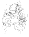
- Fig. 1 is a perspective side view of a person-support apparatus with upper body support mechanisms coupled thereto in a storage position and a person supported on the deck in a supine position according to one illustrative embodiment of the disclosure;
- Fig. 2 is a perspective side view of the person-support apparatus of Fig. 1 showing the upper body support section of the deck in a second angular orientation supporting a person in a sitting position;
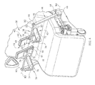
- Fig. 4 is a perspective side view of the upper body support mechanisms of Fig. 1 showing the first link, the second link, the torso support structure and the limb support structure;
- Fig. 5 is a perspective side view of the person-support apparatus of Fig. 1 showing the upper body support mechanisms according to another illustrative embodiment with a head rest coupled thereto;
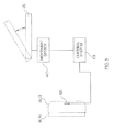
- Fig. 6 is a partial diagrammatic view of the person-support apparatus of Fig. 1 having a sensor coupled to a support cushion and configured to communicate a signal to a communication system to cause the upper body support section to move toward the first angular orientation when the person is supported on the upper body support mechanisms.
- One illustrative embodiment of the current disclosure can include an upper body support assembly coupled to a person-support apparatus and having a torso support structure configured to support the torso of a person and an arm support structure configured to support arm of the person when the person is in a forward-leaning posture in a sitting position.
- a person-support apparatus 10 is shown in Figs. 1-6 .
- the person-support apparatus 10 is a hospital bed with a first section F1 or a head support section F1, where the head of a person (not shown) can be positioned and a second section S1 or a foot support section S1, where the feet of the person (not shown) can be positioned.
- the person-support apparatus 10 includes a lower frame 12 and an upper frame 14 supported on supports 16 above the lower frame 12. It should be appreciated that the person-support apparatus 10 can also be a hospital stretcher, an operating table, or other apparatus configured to support a person thereon. It should also be appreciated that, in one illustrative embodiment, the person-support apparatus 10 can support a person-support surface 18 or mattress 18 on the upper frame 14, The supports 16 are lift mechanisms configured to move the upper frame 14 with respect to the lower frame 12.
- the upper frame 14 includes an upper frame base 20 and a deck 22 and has siderails 24, endboards 26, and upper body support mechanisms 28 coupled thereto as shown in Figs. 1-5 .
- the deck 22 can be supported on the upper frame base 20 and can include multiple sections, such as, an upper body section 30, a foot section 32, and a seat section 34.
- the sections can be configured, to pivot and/or translate with respect to the upper frame base 20 and one another.
- the upper body section 30 is configured to move from a first angular orientation where the upper body section 30 is a substantially horizontal position and the person is in a substantially supine position, as shown in Fig.
- the deck 22 is configured to cooperate with the upper frame base 20 to move the person-support apparatus 10 between a substantially horizontal position and a chair position.
- the upper body support mechanisms 28 are coupled to the upper frame 14 and configured to move between a deployed position and a storage position with respect to the upper frame 14 as shown in Figs. 1-5 .
- the upper body support mechanisms 28 are configured to support the person supported on the person-support apparatus 10 in such a way that a caregiver is able to access the back of the person's torso.
- the person is in a forward-leaning posture in a sitting position and the torso is supported at an angle between about 0° and about 45° with respect to vertical. It should be appreciated that the angle of the upper body support mechanisms 28 with respect to vertical depend on, for example, where the upper body support mechanisms 28 are coupled. to the frame and/or the size of the person.
- the position can allow for prolonged caregiver access to the back of the person's upper body for various procedures and can help reduce any discomfort that might be associated with proning.
- the position can help enhance respiratory functions by helping increase blood flow to the base of the lungs in addition to helping to remove some of the resistance to the lung expansion.
- the position can also be used for chest-wall oscillation therapy.
- the position can help reduce the amount of weight on the lungs and stomach.
- the upper body support mechanisms 28 are mirror images of one another and include a first link 36, a second link 38, a torso support structure 40, and a limb support structure 42 as shown in Figs, 1-5 .
- the upper body support mechanisms 28 can include a head support HS1 configured to support the head of the person and can include a head base HB1 with a head cushion HC1 coupled thereto and a plurality of head posts HP1 configured to be coupled to the torso support structure 40 as shown in Fig. 5
- the head posts HP1 can be a telescoping arrangement configured to increase and decrease in length of the head posts HP1 to raise and lower the height of the head support HS1 with respect to the torso support structure 40.
- the first link 36 includes a first end 44 coupled to the upper frame 14 at a first joint 46 and a second end 48 coupled to the second link 38 at a second joint 50 as shown in Figs. 1-5 .
- the first link 36 can include a telescoping arrangement (not shown) configured to increase/decrease the length of the first link 36.
- the first link 36 is configured to selectively rotate about a first rotational axis R1 passing through the first joint 38 to move the upper body support mechanisms 28 between the deployed position and the storage position.
- the upper body support mechanisms 28 can include a locking mechanism (not shown) configured to selectively maintain the upper body support mechanisms 28 in the deployed and/or storage positions.
- first link 36 can be configured to be maintained in one of multiple deployed positions that can be between about 0° and about 45° with respect to vertical. It should also be appreciated that additional locking mechanisms (not shown) can be used to restrict/maintain the positions of the second link 38, torso support structure 40, and/or limb support structure 42 with respect to one another.
- the second link 38 includes a first end 52 coupled to the first link 36 at the second joint 50 and a second end 54 coupled to the torso support structure 40 at a third joint 56 as shown, in Figs. 1-5 .
- the second link 38 can include a telescoping arrangement (not shown) configured to increase/decrease the length of the second link 38.
- the second link 38 is configured to rotate about a second rotational axis R2 passing through the second joint 50 to move the torso support structure 40 between a use position and a storage position with respect to the first link 36. In the deployed position, the second link 38 can be substantially perpendicular to the first link 36.
- the second rotational axis R2 can be substantially perpendicular to the first rotational axis R1.
- the torso support structure 40 is configured to support the torso of the person thereon and includes a torso support base 58 and a torso support cushion 60 as shown in Figs. 1-6 .
- the torso support structure 40 supports the person's chest.
- the torso support base 58 includes a first surface 62 and a second surface (not shown). It should be appreciated that the torso support, base 58 can also include head receptacles HR1 that can be configured to receive the head support HS1 as shown in Fig. 5 .
- the first surface 62 is coupled to the second link 38 at the third joint 56 and coupled to the limb support structure 42 at a fourth joint 64,
- the fourth joint 64 is positioned proximate to a first end 66 of the torso support base 58 and the third joint 56 is positioned between the fourth joint 64 and a second end 68 of the torso support base 58.
- the third joint 56 can be spaced apart from the fourth joint 64 a distance such that a person's arm can be positioned between the second link 38 and the limb support structure 42.
- the second link 38 can be coupled to the torso support base 58 at the third joint 56 and the limb support structure 42 can extend from the second link 38.
- the torso support structure 40 is configured to rotate with respect to the second link 38 about a third rotational axis R3 that passes through the second joint 50 and the third joint 56. It should be appreciated that the third rotational axis R3 can be substantially perpendicular to the second rotational axis R2.
- the torso support cushion 60 can be coupled to the second surface of the torso support base 58 and can engage the torso of the person as shown in Figs. 1-6 . It should be appreciated that the torso support cushion 60 can be coupled to the torso support base 58 with fasteners (not shown), such as, screws or rivets.
- the torso suppord cushion 60 can be configured provide a comfortable surface for the person's torso to be supported on.
- the torso support cushion 60 can be composed of a polymeric material such as, foam.
- the torso support cushion 60 includes a sensor SN1, such as, a force sensor, configured to sense when the person is being supported by the upper body support mechanisms 28 as shown in Fig. 6 .
- the sensor SN1 can be a torque sensor, a pressure sensor, a temperature, or other sensor.
- the sensor SN1 can be a torque sensor coupled to the first joint 46.
- the sensor SN1 can be coupled to the upper frame 14 and configured to sense the position, weight, and/or center of gravity of the person, which can be communicated to the control system CS1 to determine whether or not the person is supported by the upper body support mechanisms 28.
- the sensor SN1 can communicate a signal corresponding to whether or not the person is supported by the support mechanism 28 to a control system CS1 configured to control various functions of the person-support apparatus 10.
- the control system CS1 can include memory (not shown) and a processor (not shown) that can be configured to read and/or write data to the memory and execute operating logic that can be stored in the memory.
- the control system CS1 is configured to activate a movement device, such as, an actuator AC1, coupled to the upper frame base 20 and the upper body section 30 that is configured to move the upper body section 30 of the deck 22 from the second angular orientation toward the first angular orientation when the sensor SN1 indicates that the person is supported by the upper body support mechanisms 28.
- a caregiver can press a button (not shown) that can cause the control system CS1 to activate the movement device to move the upper body section 30 from the second angular orientation to the first angular orientation when the person is supported by the upper body support mechanisms 28. It should also be appreciated that the upper body section 30 can be manually lowered from the inclined position toward the substantially horizontal position.
- the limb support structure 42 is configured to support the arm of the person and includes a limb support base 70, a limb support cushion 72, and a grip 74 as shown in Figs. 1-5 . It should be appreciated that the limb support structure 42 can include a telescoping arrangement (not shown) configured to increase/decrease the length of the limb support structure 42.
- the limb support base 70 includes a first end 76 coupled to the torso support structure 40 at the fourth joint 44 and a second end 78 coupled to the grip 74.
- the limb support base 70 is configured to rotate about a fourth rotational axis That passes through the fourth joint 44 between a use position and a storage position.
- the fourth rotational axis R4 can be substantially parallel to the third rotational axis R3. In the use position, the limb support structure 42 can be substantially perpendicular to the second link 38. In the storage position, the limb support structure 42 can be substantially parallel to the torso support structure 40.
- the limb support cushion 72 is coupled to the limb support base 70 and is engaged by the forearm of the person as shown in Figs. 1-6 . It should be appreciated that the limb support cushion 72 can be coupled to the limb support base 70 with fasteners (not shown), such as screws or rivets.
- the limb support cushion 72 can be configured provide a comfortable surface for the person's arm to be supported on
- the limb support cushion 72 can be composed of a polymeric material, such as, foam.
- the limb support cushion 72 includes a sensor SN1, such as, a force sensor, configured to sense when the person is being supported by the upper body support mechanisms 28.
- the grip 74 is coupled to the second end 78 of the limb support base 70 and can be configured to be gripped by a person being supported, on the upper body support mechanisms 28 as shown in Figs. 1-5 . It should be appreciated that the grip 74 can be movably coupled to the second end 78. It should also be appreciated that the grip 74 can include control buttons (not shown) thereon that are configured to cause the control system CS1 to control a function of the person-support, apparatus 10, such as, for example, raise/lower the upper body section 30.
- the upper body section 30 is initially in the horizontal position with the person in the supine position, and the upper body support mechanisms 28 are initially in the storage position alongside the upper frame 14 such that the first link 36 is substantially parallel to the upper frame base 20 and the torso support structure 40 and the limb support structure 42 are adjacent to the seat section 30 as shown in Fig. 1 .
- the caregiver raises the upper body section 30 from a substantially horizontal position to an inclined position with respect to the upper frame base 20 to move the person from a supine position to a sitting position.
- the person's chest can define an angle of less than or equal to 90° with respect to the upper frame base 20 when the person is in the sitting position.
- the upper body support mechanisms 28 are moved from the storage position to the deployed position.
- the first link 36 is rotated about the first rotational axis R1 from the storage position toward deployed position. It should be appreciated that the upper body support mechanisms 28 are between about 0° and about 45° with respect to vertical in the deployed position.
- the second link 38 is rotated about the second rotational axis R2 until the third rotational axis R3 is substantially parallel to the first rotational axis R1 and the torso support structure 36 is positioned above the seat section 34 in the use position.
- the torso support structure 36 can be positioned over other portions of the deck 22 in the use position.
- the limb support structure 42 is moved to the use position by rotating the limb support base 70 about the fourth rotational axis R4 such that the limb support structure 42 is substantially parallel to the upper frame base 20.
- the person can lean forward (or can be leaned forward by a caregiver) in the sitting position such that they are in a forward-leaning posture when supported by the upper body support mechanisms 28.
- the control system CS1 moves the upper body section 30 from the inclined position to the substantially horizontal position once the sensors SN1 sense that the person is supported on the upper body support mechanisms 28.
- the caregiver can press a button (not shown) to move the upper body section 30 from the inclined position to the substantially horizontal position when the person is supported on the upper body support mechanisms 28.
- the caregiver can manually move the upper body section 30 from the inclined position to the substantially horizontal position.
- the limb support structure 42 is moved to the storage position first by rotating the limb support structure 42 about the fourth rotational axis R4 until the limb support cushion 72 contacts the second link 38 or is immediately adjacent to the second link 38.
- the torso support structure 40 is moved to the storage position by rotating the second link 38 about the second rotational axis R2 until the second link 38 is adjacent to the first link 36.
- the first link 36 is rotated about the first rotational axis R1 until the first link is alongside the upper frame 14 and is substantially parallel to the upper frame base 20 in the storage position as shown in Fig. 1 .
Landscapes
- Health & Medical Sciences (AREA)
- Nursing (AREA)
- Life Sciences & Earth Sciences (AREA)
- Animal Behavior & Ethology (AREA)
- General Health & Medical Sciences (AREA)
- Public Health (AREA)
- Veterinary Medicine (AREA)
- Invalid Beds And Related Equipment (AREA)
- Orthopedics, Nursing, And Contraception (AREA)
Abstract
Description
- This disclosure relates generally to upper body support assemblies coupled person-support apparatuses. More particularly, but not exclusively, this disclosure relates to an upper body support assembly configured to support a portion of the upper body of a person positioned on a person-support apparatus to help provide access to a portion of the person's upper body.
- Caregivers can require access to a portion of a person's body, such as, the back of the person's torso, while the person is supported on a person-support apparatus. While various person-support apparatuses have been developed, there is still room for improvement. Thus, a need persists for further contributions in this area of technology.
- One illustrative embodiment of the current disclosure can include an upper body support assembly coupled to a person-support apparatus and having a torso support structure configured to support the torso of a person and an arm support structure configured to support arm of the person when the person is in a forward-leaning posture in a sitting position.
- The invention will now be further described by way of example with reference to the accompanying drawings, in which:
-
Fig. 1 is a perspective side view of a person-support apparatus with upper body support mechanisms coupled thereto in a storage position and a person supported on the deck in a supine position according to one illustrative embodiment of the disclosure; -
Fig. 2 is a perspective side view of the person-support apparatus ofFig. 1 showing the upper body support section of the deck in a second angular orientation supporting a person in a sitting position; -
Fig. 3 is a perspective side view of the person-support apparatus ofFig. 1 showing the person in a forward-leaning posture in the sitting position supported by the upper body support mechanisms in the deployed position; -
Fig. 4 is a perspective side view of the upper body support mechanisms ofFig. 1 showing the first link, the second link, the torso support structure and the limb support structure; -
Fig. 5 is a perspective side view of the person-support apparatus ofFig. 1 showing the upper body support mechanisms according to another illustrative embodiment with a head rest coupled thereto; and -
Fig. 6 is a partial diagrammatic view of the person-support apparatus ofFig. 1 having a sensor coupled to a support cushion and configured to communicate a signal to a communication system to cause the upper body support section to move toward the first angular orientation when the person is supported on the upper body support mechanisms. - One illustrative embodiment of the current disclosure can include an upper body support assembly coupled to a person-support apparatus and having a torso support structure configured to support the torso of a person and an arm support structure configured to support arm of the person when the person is in a forward-leaning posture in a sitting position.
- A person-
support apparatus 10 according to one illustrative embodiment of the current disclosure is shown inFigs. 1-6 . The person-support apparatus 10 is a hospital bed with a first section F1 or a head support section F1, where the head of a person (not shown) can be positioned and a second section S1 or a foot support section S1, where the feet of the person (not shown) can be positioned. The person-support apparatus 10 includes alower frame 12 and anupper frame 14 supported onsupports 16 above thelower frame 12. It should be appreciated that the person-support apparatus 10 can also be a hospital stretcher, an operating table, or other apparatus configured to support a person thereon. It should also be appreciated that, in one illustrative embodiment, the person-support apparatus 10 can support a person-support surface 18 ormattress 18 on theupper frame 14, Thesupports 16 are lift mechanisms configured to move theupper frame 14 with respect to thelower frame 12. - The
upper frame 14 includes anupper frame base 20 and adeck 22 and hassiderails 24,endboards 26, and upperbody support mechanisms 28 coupled thereto as shown inFigs. 1-5 . Thedeck 22 can be supported on theupper frame base 20 and can include multiple sections, such as, anupper body section 30, afoot section 32, and aseat section 34. The sections can be configured, to pivot and/or translate with respect to theupper frame base 20 and one another. In one illustrative embodiment, theupper body section 30 is configured to move from a first angular orientation where theupper body section 30 is a substantially horizontal position and the person is in a substantially supine position, as shown inFig. 1 , to a second, angular orientation where theupper body section 30 is in an inclined position and the person is in a sitting position as shown inFigs. 2-5 . It should also be appreciated that thedeck 22 is configured to cooperate with theupper frame base 20 to move the person-support apparatus 10 between a substantially horizontal position and a chair position. - The upper
body support mechanisms 28 are coupled to theupper frame 14 and configured to move between a deployed position and a storage position with respect to theupper frame 14 as shown inFigs. 1-5 . In the deployed position, the upperbody support mechanisms 28 are configured to support the person supported on the person-support apparatus 10 in such a way that a caregiver is able to access the back of the person's torso. In one illustrative embodiment, the person is in a forward-leaning posture in a sitting position and the torso is supported at an angle between about 0° and about 45° with respect to vertical. It should be appreciated that the angle of the upperbody support mechanisms 28 with respect to vertical depend on, for example, where the upperbody support mechanisms 28 are coupled. to the frame and/or the size of the person. The position can allow for prolonged caregiver access to the back of the person's upper body for various procedures and can help reduce any discomfort that might be associated with proning. In one example, the position can help enhance respiratory functions by helping increase blood flow to the base of the lungs in addition to helping to remove some of the resistance to the lung expansion. In another example, the position can also be used for chest-wall oscillation therapy. In another example, the position can help reduce the amount of weight on the lungs and stomach. - The upper
body support mechanisms 28 are mirror images of one another and include afirst link 36, asecond link 38, atorso support structure 40, and alimb support structure 42 as shown inFigs, 1-5 . It should be appreciated that the upperbody support mechanisms 28 can include a head support HS1 configured to support the head of the person and can include a head base HB1 with a head cushion HC1 coupled thereto and a plurality of head posts HP1 configured to be coupled to thetorso support structure 40 as shown inFig. 5 , It should also be appreciated that the head posts HP1 can be a telescoping arrangement configured to increase and decrease in length of the head posts HP1 to raise and lower the height of the head support HS1 with respect to thetorso support structure 40. - The
first link 36 includes afirst end 44 coupled to theupper frame 14 at afirst joint 46 and asecond end 48 coupled to thesecond link 38 at asecond joint 50 as shown inFigs. 1-5 . It should be appreciated that thefirst link 36 can include a telescoping arrangement (not shown) configured to increase/decrease the length of thefirst link 36. Thefirst link 36 is configured to selectively rotate about a first rotational axis R1 passing through thefirst joint 38 to move the upperbody support mechanisms 28 between the deployed position and the storage position. It should be appreciated that the upperbody support mechanisms 28 can include a locking mechanism (not shown) configured to selectively maintain the upperbody support mechanisms 28 in the deployed and/or storage positions. It should also be appreciated thatfirst link 36 can be configured to be maintained in one of multiple deployed positions that can be between about 0° and about 45° with respect to vertical. It should also be appreciated that additional locking mechanisms (not shown) can be used to restrict/maintain the positions of thesecond link 38,torso support structure 40, and/orlimb support structure 42 with respect to one another. - The
second link 38 includes afirst end 52 coupled to thefirst link 36 at thesecond joint 50 and asecond end 54 coupled to thetorso support structure 40 at athird joint 56 as shown, inFigs. 1-5 . It should be appreciated that thesecond link 38 can include a telescoping arrangement (not shown) configured to increase/decrease the length of thesecond link 38. Thesecond link 38 is configured to rotate about a second rotational axis R2 passing through thesecond joint 50 to move thetorso support structure 40 between a use position and a storage position with respect to thefirst link 36. In the deployed position, thesecond link 38 can be substantially perpendicular to thefirst link 36. The second rotational axis R2 can be substantially perpendicular to the first rotational axis R1. - The
torso support structure 40 is configured to support the torso of the person thereon and includes atorso support base 58 and atorso support cushion 60 as shown inFigs. 1-6 . In one illustrative embodiment, thetorso support structure 40 supports the person's chest. Thetorso support base 58 includes a first surface 62 and a second surface (not shown). It should be appreciated that the torso support,base 58 can also include head receptacles HR1 that can be configured to receive the head support HS1 as shown inFig. 5 . The first surface 62 is coupled to thesecond link 38 at thethird joint 56 and coupled to thelimb support structure 42 at afourth joint 64, In one illustrative embodiment, thefourth joint 64 is positioned proximate to afirst end 66 of thetorso support base 58 and thethird joint 56 is positioned between thefourth joint 64 and a second end 68 of thetorso support base 58. It should be appreciated that thethird joint 56 can be spaced apart from the fourth joint 64 a distance such that a person's arm can be positioned between thesecond link 38 and thelimb support structure 42. It should also be appreciated that thesecond link 38 can be coupled to thetorso support base 58 at thethird joint 56 and thelimb support structure 42 can extend from thesecond link 38. Thetorso support structure 40 is configured to rotate with respect to thesecond link 38 about a third rotational axis R3 that passes through thesecond joint 50 and thethird joint 56. It should be appreciated that the third rotational axis R3 can be substantially perpendicular to the second rotational axis R2. - The
torso support cushion 60 can be coupled to the second surface of thetorso support base 58 and can engage the torso of the person as shown inFigs. 1-6 . It should be appreciated that thetorso support cushion 60 can be coupled to thetorso support base 58 with fasteners (not shown), such as, screws or rivets. Thetorso suppord cushion 60 can be configured provide a comfortable surface for the person's torso to be supported on. Thetorso support cushion 60 can be composed of a polymeric material such as, foam. - In one illustrative embodiment, the
torso support cushion 60 includes a sensor SN1, such as, a force sensor, configured to sense when the person is being supported by the upperbody support mechanisms 28 as shown inFig. 6 . It should be appreciated that the sensor SN1 can be a torque sensor, a pressure sensor, a temperature, or other sensor. It should also be appreciated that the sensor SN1 can be a torque sensor coupled to thefirst joint 46. It should also be appreciated that the sensor SN1 can be coupled to theupper frame 14 and configured to sense the position, weight, and/or center of gravity of the person, which can be communicated to the control system CS1 to determine whether or not the person is supported by the upperbody support mechanisms 28. The sensor SN1 can communicate a signal corresponding to whether or not the person is supported by thesupport mechanism 28 to a control system CS1 configured to control various functions of the person-support apparatus 10. It should be appreciated that the control system CS1 can include memory (not shown) and a processor (not shown) that can be configured to read and/or write data to the memory and execute operating logic that can be stored in the memory. In one illustrative embodiment, the control system CS1 is configured to activate a movement device, such as, an actuator AC1, coupled to theupper frame base 20 and theupper body section 30 that is configured to move theupper body section 30 of thedeck 22 from the second angular orientation toward the first angular orientation when the sensor SN1 indicates that the person is supported by the upperbody support mechanisms 28. In another illustrative embodiment, a caregiver can press a button (not shown) that can cause the control system CS1 to activate the movement device to move theupper body section 30 from the second angular orientation to the first angular orientation when the person is supported by the upperbody support mechanisms 28. It should also be appreciated that theupper body section 30 can be manually lowered from the inclined position toward the substantially horizontal position. - The
limb support structure 42 is configured to support the arm of the person and includes alimb support base 70, alimb support cushion 72, and agrip 74 as shown inFigs. 1-5 . It should be appreciated that thelimb support structure 42 can include a telescoping arrangement (not shown) configured to increase/decrease the length of thelimb support structure 42. Thelimb support base 70 includes a first end 76 coupled to thetorso support structure 40 at the fourth joint 44 and asecond end 78 coupled to thegrip 74. Thelimb support base 70 is configured to rotate about a fourth rotational axis That passes through the fourth joint 44 between a use position and a storage position. The fourth rotational axis R4 can be substantially parallel to the third rotational axis R3. In the use position, thelimb support structure 42 can be substantially perpendicular to thesecond link 38. In the storage position, thelimb support structure 42 can be substantially parallel to thetorso support structure 40. - The
limb support cushion 72 is coupled to thelimb support base 70 and is engaged by the forearm of the person as shown inFigs. 1-6 . It should be appreciated that thelimb support cushion 72 can be coupled to thelimb support base 70 with fasteners (not shown), such as screws or rivets. Thelimb support cushion 72 can be configured provide a comfortable surface for the person's arm to be supported on Thelimb support cushion 72 can be composed of a polymeric material, such as, foam. In one illustrative embodiment, thelimb support cushion 72 includes a sensor SN1, such as, a force sensor, configured to sense when the person is being supported by the upperbody support mechanisms 28. - The
grip 74 is coupled to thesecond end 78 of thelimb support base 70 and can be configured to be gripped by a person being supported, on the upperbody support mechanisms 28 as shown inFigs. 1-5 . It should be appreciated that thegrip 74 can be movably coupled to thesecond end 78. It should also be appreciated that thegrip 74 can include control buttons (not shown) thereon that are configured to cause the control system CS1 to control a function of the person-support,apparatus 10, such as, for example, raise/lower theupper body section 30. - In operation, the
upper body section 30 is initially in the horizontal position with the person in the supine position, and the upperbody support mechanisms 28 are initially in the storage position alongside theupper frame 14 such that thefirst link 36 is substantially parallel to theupper frame base 20 and thetorso support structure 40 and thelimb support structure 42 are adjacent to theseat section 30 as shown inFig. 1 . The caregiver raises theupper body section 30 from a substantially horizontal position to an inclined position with respect to theupper frame base 20 to move the person from a supine position to a sitting position. It should be appreciated that the person's chest can define an angle of less than or equal to 90° with respect to theupper frame base 20 when the person is in the sitting position. - Once the person is in the sitting position, the upper
body support mechanisms 28 are moved from the storage position to the deployed position. To move thesupport mechanism 28 from the storage position to the deployed position, thefirst link 36 is rotated about the first rotational axis R1 from the storage position toward deployed position. It should be appreciated that the upperbody support mechanisms 28 are between about 0° and about 45° with respect to vertical in the deployed position. Once thefirst link 36 is in the use position, thesecond link 38 is rotated about the second rotational axis R2 until the third rotational axis R3 is substantially parallel to the first rotational axis R1 and thetorso support structure 36 is positioned above theseat section 34 in the use position. It should also be appreciated that thetorso support structure 36 can be positioned over other portions of thedeck 22 in the use position. After thetorso support structure 40 is in the use position, thelimb support structure 42 is moved to the use position by rotating thelimb support base 70 about the fourth rotational axis R4 such that thelimb support structure 42 is substantially parallel to theupper frame base 20. - Once the upper
body support mechanisms 28 are fully deployed, as shown inFigs. 2-6 , the person can lean forward (or can be leaned forward by a caregiver) in the sitting position such that they are in a forward-leaning posture when supported by the upperbody support mechanisms 28. In one illustrative embodiment, the control system CS1 moves theupper body section 30 from the inclined position to the substantially horizontal position once the sensors SN1 sense that the person is supported on the upperbody support mechanisms 28. It should be appreciated that the caregiver can press a button (not shown) to move theupper body section 30 from the inclined position to the substantially horizontal position when the person is supported on the upperbody support mechanisms 28. It should also be appreciated that the caregiver can manually move theupper body section 30 from the inclined position to the substantially horizontal position. - To move the
support mechanism 28 from the deployed position to the storage position, thelimb support structure 42 is moved to the storage position first by rotating thelimb support structure 42 about the fourth rotational axis R4 until thelimb support cushion 72 contacts thesecond link 38 or is immediately adjacent to thesecond link 38. Next, thetorso support structure 40 is moved to the storage position by rotating thesecond link 38 about the second rotational axis R2 until thesecond link 38 is adjacent to thefirst link 36. Finally, thefirst link 36 is rotated about the first rotational axis R1 until the first link is alongside theupper frame 14 and is substantially parallel to theupper frame base 20 in the storage position as shown inFig. 1 . - While embodiments of the disclosure have been illustrated and described in detail in the drawings and foregoing description, the same are to be considered as illustrative and not intended to be exhaustive or to limit the disclosure to the precise forms disclosed. Additional alternatives, modifications and variations can be apparent to those skilled in the art. Also, while multiple inventive aspects and principles can have been presented, they need not be utilized in combination, and various combinations of inventive aspects and principles are possible in light of the various embodiments provided.
- Embodiments of the invention can be described with reference to the following numbered clauses, with preferred features laid out in the dependent clauses:
- 1. A person-support apparatus, comprising:
- a frame;
- a deck coupled to the frame and configured to support a person, the deck including a first section and a second section, the first section being configured to pivot between a first angular orientation and a second angular orientation with respect to the frame, wherein the person is in a supine position when the first section is in the first angular orientation and is moved to a sitting position when the first section is moved to the second angular orientation; and
- an upper body support assembly movably coupled to the frame and including a torso support, the torso support being configured to support a portion of the person's torso when the person is in a forward-leaning posture in the sitting position.
- 2. The person-support apparatus of clause 1, wherein the upper body support assembly also includes an arm support configured to support at least a portion of the person's arm.
- 3. The person-support apparatus of clause 2, wherein the arm support includes a cushion coupled thereto.
- 4. The person-support apparatus of clause 2, wherein the arm support includes a grip configured to be gripped by the person.
- 5. The person-support apparatus of clause 1, wherein the torso support includes a cushion coupled thereto.
- 6. The person-support apparatus of clause 1, wherein the first section of the deck is manually moved from the second angular orientation to the first angular orientation when the person is supported by the upper body support assembly.
- 7. The person-support apparatus of clause 1, wherein the first section of the deck is automatically moved from the second angular orientation to the first angular orientation when the person is supported by the upper body support assembly.
- 8. The person-support apparatus of clause 1, wherein a button is pressed to move the first section of the deck from the second angular orientation to the first angular orientation when the person is supported by the upper body support assembly.
- 9. The person-support apparatus of clause 1, wherein the upper body support is configured to move with respect to the frame independent of the deck.
- 10. A person-support apparatus, comprising:
- a lower frame;
- a lift mechanism coupled to the lower frame;
- an upper frame movably supported above the lower frame by the lift mechanism; a siderail coupled to the upper frame and configured to locate an edge of the upper frame; and
- an upper body support assembly movably coupled to the upper frame and configured to move between a storage position and a deployed position, the upper body support assembly being configured to support the chest of the person when the upper body support assembly is in the deployed position and the person is in a sitting position.
- 11. The person-support apparatus of
clause 10, wherein the upper body support assembly includes a chest support, configured to support the person's chest, the chest support including a cushion coupled thereto. - 12. The person-support apparatus of
clause 10, wherein the upper body support, assembly includes an arm support configured to support at least a portion of the person's arm. - 13. The person-support apparatus of
clause 12, wherein the arm support includes a cushion coupled thereto. - 14. The person-support apparatus of
clause 12, wherein the arm support includes a grip configured to be gripped by the person. - 15. The person-support apparatus of
clause 10, wherein the upper body support assembly includes a head support configured to support a portion of the person's head. - 16. The person-support apparatus of
clause 10, wherein the upper frame includes a deck with a first section and a second section, the first section being pivotable between a first angular orientation and a second angular orientation with respect to the second section, the first section being configured to support a person in a supine position in the first angular orientation and move the person from the supine position to the sitting position as the first section moves to the second angular orientation. - 17. The person-support apparatus of
clause 10, wherein the person is in a forward-leaning posture in the sitting position when supported by the upper body support assembly. - 18. A person-support apparatus, comprising:
- a frame configured to support a person thereon;
- an upper body support assembly movably coupled to the frame and being configured to support-the upper body of the person when the person is in a sitting position; and
- a sensor configured to sense when the upper body of the person is being supported by the upper body support assembly.
- 19. The person-support apparatus of
clause 18 further comprising a deck coupled to the frame, the deck including a first section and a second section, the first section being configured to pivot between a first angular orientation and a second angular orientation with respect to the frame, the person being substantially in a supine position when the first section is at the first angular orientation with respect to the frame and being in a substantially sitting position when the first section is at the second angular orientation with respect to the frame. - 20. The person-support apparatus of clause 19, wherein the first section is configured to move from the second angular orientation to the first angular orientation when the sensor senses that the upper body of the person is supported by the upper body support assembly.
- 21. The person-support apparatus of
clause 18, wherein the upper body support assembly includes a chest support configured to support the person's chest - 22. The person-support apparatus of
clause 18, wherein the upper body support assembly includes an arm support configured to support the person's arms. - 23. The person-support apparatus of
clause 18, wherein the upper body support assembly includes a head support configured to support a portion of the person's head. - 24. The person-support apparatus of
clause 18, wherein the upper body support assembly includes at least one of a torso supped, an arm support, and a head support, the sensor is coupled to the at least one of the torso support, the arm support, and the head support. - 25. The person-support apparatus of
clause 18, wherein the upper body support assembly includes at least one of a torso support, an arm support, and a head support, the at least one of the torso support, the arm support, and the head support includes a cushion coupled thereto. - 26. The person-support apparatus of clause 25, wherein the sensor is coupled to the cushion.
- 27. The person-support apparatus of
clause 18, wherein the upper body support assembly is rotatably coupled to the frame at a first joint, the sensor being coupled to the first joint. - 28. The person-support apparatus of
clause 18, wherein the person is in a forward-leaning posture in the sitting position when supported by the upper body support assembly.
Claims (15)
- A persn-support apparatus 10, comprising:a frame 20;a deck 22 coupled to the frame 20 and configured to support a person, the deck 22 including a first section 30 and a second section 34, the first section 30 being configured to pivot between a first angular orientation and a second angular orientation with respect to the frame 20, wherein the person is in a first position when the first section 30 is in the first angular orientation and is moved to a second position when the first section 30 is moved to the second angular orientation; andan upper body support, assembly 28 movably coupled to the frame 20 and including a torso support 40, the torso support 40 being configured to support a portion of the person's torso when the person is in a forward-leaning posture in the second position.
- The person-support apparatus 10 of claim 1, wherein the upper body support assembly 28 also includes an arm support 42 configured to support at least a portion of the person's arm.
- The person-support apparatus 10 of claim 2, wherein the arm support 42 includes a cushion 72 coupled thereto.
- The person-support apparatus 10 of either claim 2 or claim 3, wherein the arm support 42 includes a grip 74 configured to be gripped by the person.
- The person-support apparatus 10 of any preceding claim, wherein the torso support 40 includes a cushion 60 coupled thereto.
- The person-support apparatus 10 of any preceding claim, wherein the first section 30 of the deck 22 is moved from the second angular orientation to the first angular orientation when the person is supported by the upper body support assembly 28,
- The person-support apparatus 10 of any preceding claim, wherein the upper body support assembly 28 includes a head support HS1 configured to support a portion of the person's head.
- The person-support apparatus 1 0 of any preceding claim further comprising a sensor SN1 configured to sense when the upper body of the person is being supported by the upper body support assembly 28.
- The person-support apparatus 10 of claim 8, the first section 30 is configured to move from the second angular orientation to the first angular orientation when the sensor SN1 senses that the upper body of the person is supported by the upper body support assembly 28.
- The person-support apparatus 10 of claim 8, wherein the sensor SN1 is coupled to the at least one of the torso support 40, an arm support 42, and a head support HS1.
- The person-support apparatus 10 of any one of claims 1 to 9, wherein the upper body support assembly 28 includes at least one of the torso support 40, an arm support 42, and a head support HS1, the at least one of the torso support 40, the arm support 42, and the head support HS1 includes a cushion 60, 72, HC1 coupled thereto.
- The person-support apparatus 10 of claim 11 as dependent on claim 8 or claim 9, wherein a sensor SN1 is coupled to the cushion 60, 72, HC1 and is configured to sense when the upper body of the person is being supported by the upper body support assembly 28.
- The person-support apparatus 10 of claim 8 or claim 9, wherein the upper body support assembly 28 is rotatably coupled to the frame 20 at a first joint 46 and the sensor SN1 is coupled to the first joint 46.
- The person-support apparatus of any preceding claim, wherein the upper body support is configured to move with respect to the frame independent of the deck.
- The person-support apparatus of any preceding claim, wherein the upper body support assembly includes a head support configured to support a portion of the person's head.
Applications Claiming Priority (1)
| Application Number | Priority Date | Filing Date | Title |
|---|---|---|---|
| US12/892,977 US8732876B2 (en) | 2010-09-29 | 2010-09-29 | Upper body support mechanism |
Publications (2)
| Publication Number | Publication Date |
|---|---|
| EP2436354A2 true EP2436354A2 (en) | 2012-04-04 |
| EP2436354A3 EP2436354A3 (en) | 2013-04-17 |
Family
ID=44719535
Family Applications (1)
| Application Number | Title | Priority Date | Filing Date |
|---|---|---|---|
| EP11183124.4A Withdrawn EP2436354A3 (en) | 2010-09-29 | 2011-09-28 | Upper body support assembly |
Country Status (2)
| Country | Link |
|---|---|
| US (1) | US8732876B2 (en) |
| EP (1) | EP2436354A3 (en) |
Families Citing this family (16)
| Publication number | Priority date | Publication date | Assignee | Title |
|---|---|---|---|---|
| US8713727B2 (en) | 2010-07-30 | 2014-05-06 | Hill-Rom Services, Inc. | Siderail assembly for patient support apparatus |
| US8677535B2 (en) * | 2010-10-08 | 2014-03-25 | Hill-Rom Services, Inc. | Patient support apparatus with storable egress handles |
| US8745786B2 (en) | 2010-11-10 | 2014-06-10 | Hill-Rom Services, Inc. | Siderail assembly for patient support apparatus |
| US9498397B2 (en) | 2012-04-16 | 2016-11-22 | Allen Medical Systems, Inc. | Dual column surgical support system |
| US10492973B2 (en) | 2015-01-05 | 2019-12-03 | Allen Medical Systems, Inc. | Dual modality prone spine patient support apparatuses |
| AU2015383978B2 (en) * | 2015-02-27 | 2020-04-30 | Direct Healthcare Group Limited | Method and equipment for raising a lying person |
| US10363189B2 (en) | 2015-10-23 | 2019-07-30 | Allen Medical Systems, Inc. | Surgical patient support for accommodating lateral-to-prone patient positioning |
| US10561559B2 (en) | 2015-10-23 | 2020-02-18 | Allen Medical Systems, Inc. | Surgical patient support system and method for lateral-to-prone support of a patient during spine surgery |
| US10548793B2 (en) | 2016-06-14 | 2020-02-04 | Allen Medical Systems, Inc. | Pinless loading for spine table |
| US11213448B2 (en) | 2017-07-31 | 2022-01-04 | Allen Medical Systems, Inc. | Rotation lockout for surgical support |
| US11202731B2 (en) | 2018-02-28 | 2021-12-21 | Allen Medical Systems, Inc. | Surgical patient support and methods thereof |
| US11471354B2 (en) | 2018-08-30 | 2022-10-18 | Allen Medical Systems, Inc. | Patient support with selectable pivot |
| CN210095215U (en) * | 2018-11-16 | 2020-02-21 | 杨松 | Electric bed |
| DE202023003005U1 (en) * | 2022-08-02 | 2025-07-30 | Sleep Number Corporation | Systems for detecting existing varnishes in beds |
| US12599526B2 (en) | 2023-06-30 | 2026-04-14 | Allen Medical Systems, Inc. | Surgical support system with support top height adjustment |
| CN117137754A (en) * | 2023-08-25 | 2023-12-01 | 上海品兴医疗设备有限公司 | Operating bed |
Citations (2)
| Publication number | Priority date | Publication date | Assignee | Title |
|---|---|---|---|---|
| EP0663199A1 (en) | 1994-01-18 | 1995-07-19 | Nova Technologies, Inc. | Patient transfer seat |
| US20100237215A1 (en) * | 2009-03-19 | 2010-09-23 | Glenn Dahl | Patient support |
Family Cites Families (36)
| Publication number | Priority date | Publication date | Assignee | Title |
|---|---|---|---|---|
| US1279120A (en) * | 1916-12-05 | 1918-09-17 | John H Kellogg | Electrotherapeutical chair. |
| US3100129A (en) * | 1961-08-21 | 1963-08-06 | Shampaine Ind Inc | Surgical furniture |
| US4247091A (en) * | 1979-02-08 | 1981-01-27 | Borg-Warner Corporation | Adjustable labor-delivery-recovery hospital bed |
| SE434910B (en) * | 1981-02-13 | 1984-08-27 | Landstingens Inkopscentral | DEVICE FOR ADJUSTING FOOTSTEPS AND BENEFITS AT A RELEASE TABLE |
| US4541622A (en) * | 1983-12-22 | 1985-09-17 | Kazuhisa Tabuchi | Reclining bed for childbirth |
| US4650249A (en) | 1984-12-31 | 1987-03-17 | Hector Serber | Ergonomic seating assembly system with front chest support component, pelvic tilt seat component and related attachments |
| US4834457A (en) | 1987-08-28 | 1989-05-30 | Head Henry O | Upper torso support |
| US6374436B1 (en) * | 1994-01-25 | 2002-04-23 | Hill-Rom Services, Inc. | Hospital bed |
| US5131106A (en) * | 1990-08-30 | 1992-07-21 | Jackson Roger P | Spinal surgery table |
| US5088706A (en) * | 1990-08-30 | 1992-02-18 | Jackson Roger P | Spinal surgery table |
| US5060327A (en) * | 1990-10-18 | 1991-10-29 | Hill-Rom Company, Inc. | Labor grips for birthing bed |
| US5487590A (en) * | 1994-06-30 | 1996-01-30 | Haynes; Robin | Chair to promulgate kinesthetic therapy: apparatus and method |
| US5600857A (en) | 1994-11-09 | 1997-02-11 | Heilmann; Steve | Vehicle for carrying a disabled person |
| US5762402A (en) | 1996-05-06 | 1998-06-09 | Gillotti; Michael | Adjustable massage chair |
| US5971485A (en) * | 1997-05-30 | 1999-10-26 | Clark; Roland | Adjustable, folding chair for massage |
| US5800012A (en) | 1997-07-09 | 1998-09-01 | Ziegler; Douglas K. | Impact pad for a safety seat |
| EP1028685B1 (en) * | 1997-11-07 | 2005-04-06 | Hill-Rom Services, Inc. | Surgical table apparatus |
| US6076527A (en) | 1998-01-08 | 2000-06-20 | Rottinghaus; Herman James | Adaptive patient support and restraint system |
| US6065808A (en) | 1998-11-25 | 2000-05-23 | Tinsley; Ronald E. | Massage chair |
| US6698431B1 (en) | 1999-09-01 | 2004-03-02 | Compass Institute, Inc. | Apparatus and method for supporting human body during itimate activity |
| WO2001045628A2 (en) * | 1999-12-13 | 2001-06-28 | Hill-Rom, Inc. | Accessories for a patient support apparatus |
| AU2001282956A1 (en) * | 2000-07-27 | 2002-02-13 | Hill-Rom Services, Inc. | Epidural patient support |
| US6729690B2 (en) | 2000-12-05 | 2004-05-04 | Earthlite Massage Tables Inc. | Compact foldable massage chair |
| US6619747B2 (en) * | 2001-04-25 | 2003-09-16 | Kam Ko | Torso and forearm supporting device for chairs and workstands |
| CA2470004A1 (en) | 2001-12-14 | 2003-06-26 | John T. Lloyd | Portable massage chair |
| US7178868B2 (en) | 2003-05-09 | 2007-02-20 | Richardson Charlene F | Gardening chair |
| US7676862B2 (en) * | 2004-09-13 | 2010-03-16 | Kreg Medical, Inc. | Siderail for hospital bed |
| US7581266B2 (en) * | 2004-12-03 | 2009-09-01 | Stryker Corporation | Calf support assembly for a maternity bed foot support and abduction assembly |
| EP1827348A2 (en) | 2004-12-07 | 2007-09-05 | Tylerton International Inc. | Device and method for training, rehabilitation and/or support |
| US7536734B2 (en) * | 2005-01-31 | 2009-05-26 | Hill-Rom Services, Inc. | Birthing support apparatus |
| US7452032B1 (en) * | 2005-09-27 | 2008-11-18 | Earthlite Massage Tables, Inc. | Armrest assembly for a resting device |
| WO2007059045A2 (en) | 2005-11-11 | 2007-05-24 | Zubio, Inc. | A system for massaging a person |
| US7681266B2 (en) | 2006-01-06 | 2010-03-23 | Randy Jean Gerlach | Adjustable recliner bed |
| US20080235875A1 (en) * | 2007-03-28 | 2008-10-02 | Stryker Corporation | Maternity bed and patient lying surface therefor |
| US20090199339A1 (en) * | 2008-02-11 | 2009-08-13 | Martin Manufacturing Company, Llc | Medical examination table and system for mounting accessories to the table |
| US20100242176A1 (en) | 2009-03-31 | 2010-09-30 | Newkirk David C | Maternity Grip |
-
2010
- 2010-09-29 US US12/892,977 patent/US8732876B2/en active Active
-
2011
- 2011-09-28 EP EP11183124.4A patent/EP2436354A3/en not_active Withdrawn
Patent Citations (2)
| Publication number | Priority date | Publication date | Assignee | Title |
|---|---|---|---|---|
| EP0663199A1 (en) | 1994-01-18 | 1995-07-19 | Nova Technologies, Inc. | Patient transfer seat |
| US20100237215A1 (en) * | 2009-03-19 | 2010-09-23 | Glenn Dahl | Patient support |
Also Published As
| Publication number | Publication date |
|---|---|
| US8732876B2 (en) | 2014-05-27 |
| EP2436354A3 (en) | 2013-04-17 |
| US20120073051A1 (en) | 2012-03-29 |
Similar Documents
| Publication | Publication Date | Title |
|---|---|---|
| US8732876B2 (en) | Upper body support mechanism | |
| JP7587610B2 (en) | Hospital bed with drainage bag sensor - Patent application | |
| US8713727B2 (en) | Siderail assembly for patient support apparatus | |
| US8745786B2 (en) | Siderail assembly for patient support apparatus | |
| US9173797B2 (en) | Siderail assembly for patient support apparatus | |
| EP2433605B1 (en) | Mattress of a bed-chair with variable length of seating area | |
| US8413270B2 (en) | Siderail assembly for patient support apparatus | |
| US12377004B2 (en) | Patient support systems with a chair configuration and a stowable foot section | |
| US6928673B2 (en) | Siderail pad for hospital bed | |
| US8677535B2 (en) | Patient support apparatus with storable egress handles | |
| JP3926844B2 (en) | Hospital bed mattress | |
| US6978500B2 (en) | Foot controls for a bed | |
| US8732875B2 (en) | Patient support apparatus with movable siderail assembly | |
| JP2003310668A (en) | Movable bed | |
| AU2010201252A1 (en) | Maternity grip | |
| US10729246B2 (en) | Person support apparatus with shear-reducing pivot assembly | |
| US11273087B1 (en) | Autonomus and user-input reconfigurable proning bed and method for reconfiguring proning bed in the treatment of acute respiratory distress syndrome (ARDS) | |
| KR20170101333A (en) | electric wheelchair for bad-movement | |
| JP4255112B2 (en) | Bed that can be raised | |
| KR102519950B1 (en) | Medical bed | |
| JP2002085481A (en) | Bed and pillow | |
| JP2025102177A (en) | Bed device and bed device system | |
| JP2002035052A (en) | Mat device for caring | |
| US20250177227A1 (en) | Person support apparatuses including intubation assistance devices and methods of using the same | |
| JPS5841947Y2 (en) | Bedsore correction mechanism for bed with reclining mechanism |
Legal Events
| Date | Code | Title | Description |
|---|---|---|---|
| PUAI | Public reference made under article 153(3) epc to a published international application that has entered the european phase |
Free format text: ORIGINAL CODE: 0009012 |
|
| AK | Designated contracting states |
Kind code of ref document: A2 Designated state(s): AL AT BE BG CH CY CZ DE DK EE ES FI FR GB GR HR HU IE IS IT LI LT LU LV MC MK MT NL NO PL PT RO RS SE SI SK SM TR |
|
| AX | Request for extension of the european patent |
Extension state: BA ME |
|
| PUAL | Search report despatched |
Free format text: ORIGINAL CODE: 0009013 |
|
| AK | Designated contracting states |
Kind code of ref document: A3 Designated state(s): AL AT BE BG CH CY CZ DE DK EE ES FI FR GB GR HR HU IE IS IT LI LT LU LV MC MK MT NL NO PL PT RO RS SE SI SK SM TR |
|
| AX | Request for extension of the european patent |
Extension state: BA ME |
|
| RIC1 | Information provided on ipc code assigned before grant |
Ipc: A61G 7/07 20060101AFI20130308BHEP Ipc: A61G 7/16 20060101ALI20130308BHEP |
|
| RAP1 | Party data changed (applicant data changed or rights of an application transferred) |
Owner name: HILL-ROM SERVICES, INC. |
|
| RIN1 | Information on inventor provided before grant (corrected) |
Inventor name: O'KEEFE, CHRISTOPHER R. Inventor name: LACHENBRUCH, CHARLES, A. Inventor name: WILLIAMSON, RACHEL |
|
| 17P | Request for examination filed |
Effective date: 20131016 |
|
| RBV | Designated contracting states (corrected) |
Designated state(s): AL AT BE BG CH CY CZ DE DK EE ES FI FR GB GR HR HU IE IS IT LI LT LU LV MC MK MT NL NO PL PT RO RS SE SI SK SM TR |
|
| 17Q | First examination report despatched |
Effective date: 20140122 |
|
| STAA | Information on the status of an ep patent application or granted ep patent |
Free format text: STATUS: THE APPLICATION IS DEEMED TO BE WITHDRAWN |
|
| 18D | Application deemed to be withdrawn |
Effective date: 20140802 |