EP2436316B1 - Suture anchor with suture management - Google Patents
Suture anchor with suture management Download PDFInfo
- Publication number
- EP2436316B1 EP2436316B1 EP11183317.4A EP11183317A EP2436316B1 EP 2436316 B1 EP2436316 B1 EP 2436316B1 EP 11183317 A EP11183317 A EP 11183317A EP 2436316 B1 EP2436316 B1 EP 2436316B1
- Authority
- EP
- European Patent Office
- Prior art keywords
- suture
- anchor
- attachment
- abutment surface
- axial bore
- Prior art date
- Legal status (The legal status is an assumption and is not a legal conclusion. Google has not performed a legal analysis and makes no representation as to the accuracy of the status listed.)
- Not-in-force
Links
- 210000000988 bone and bone Anatomy 0.000 claims description 27
- 241000894006 Bacteria Species 0.000 claims description 2
- 210000004872 soft tissue Anatomy 0.000 description 4
- 238000003780 insertion Methods 0.000 description 3
- 230000037431 insertion Effects 0.000 description 3
- 230000008468 bone growth Effects 0.000 description 2
- 210000000513 rotator cuff Anatomy 0.000 description 2
- 210000002435 tendon Anatomy 0.000 description 2
- 238000004873 anchoring Methods 0.000 description 1
- 230000001054 cortical effect Effects 0.000 description 1
- 230000000694 effects Effects 0.000 description 1
- 230000002708 enhancing effect Effects 0.000 description 1
- 210000003041 ligament Anatomy 0.000 description 1
- 238000004519 manufacturing process Methods 0.000 description 1
- 239000002184 metal Substances 0.000 description 1
- 238000000034 method Methods 0.000 description 1
- 230000000717 retained effect Effects 0.000 description 1
- 238000010079 rubber tapping Methods 0.000 description 1
- 238000000926 separation method Methods 0.000 description 1
- 239000007787 solid Substances 0.000 description 1
- 210000001519 tissue Anatomy 0.000 description 1
Images


Classifications
-
- A—HUMAN NECESSITIES
- A61—MEDICAL OR VETERINARY SCIENCE; HYGIENE
- A61B—DIAGNOSIS; SURGERY; IDENTIFICATION
- A61B17/00—Surgical instruments, devices or methods
- A61B17/04—Surgical instruments, devices or methods for suturing wounds; Holders or packages for needles or suture materials
- A61B17/0401—Suture anchors, buttons or pledgets, i.e. means for attaching sutures to bone, cartilage or soft tissue; Instruments for applying or removing suture anchors
-
- A—HUMAN NECESSITIES
- A61—MEDICAL OR VETERINARY SCIENCE; HYGIENE
- A61B—DIAGNOSIS; SURGERY; IDENTIFICATION
- A61B17/00—Surgical instruments, devices or methods
- A61B17/04—Surgical instruments, devices or methods for suturing wounds; Holders or packages for needles or suture materials
- A61B17/0401—Suture anchors, buttons or pledgets, i.e. means for attaching sutures to bone, cartilage or soft tissue; Instruments for applying or removing suture anchors
- A61B2017/0409—Instruments for applying suture anchors
-
- A—HUMAN NECESSITIES
- A61—MEDICAL OR VETERINARY SCIENCE; HYGIENE
- A61B—DIAGNOSIS; SURGERY; IDENTIFICATION
- A61B17/00—Surgical instruments, devices or methods
- A61B17/04—Surgical instruments, devices or methods for suturing wounds; Holders or packages for needles or suture materials
- A61B17/0401—Suture anchors, buttons or pledgets, i.e. means for attaching sutures to bone, cartilage or soft tissue; Instruments for applying or removing suture anchors
- A61B2017/0412—Suture anchors, buttons or pledgets, i.e. means for attaching sutures to bone, cartilage or soft tissue; Instruments for applying or removing suture anchors having anchoring barbs or pins extending outwardly from suture anchor body
-
- A—HUMAN NECESSITIES
- A61—MEDICAL OR VETERINARY SCIENCE; HYGIENE
- A61B—DIAGNOSIS; SURGERY; IDENTIFICATION
- A61B17/00—Surgical instruments, devices or methods
- A61B17/04—Surgical instruments, devices or methods for suturing wounds; Holders or packages for needles or suture materials
- A61B17/0401—Suture anchors, buttons or pledgets, i.e. means for attaching sutures to bone, cartilage or soft tissue; Instruments for applying or removing suture anchors
- A61B2017/0414—Suture anchors, buttons or pledgets, i.e. means for attaching sutures to bone, cartilage or soft tissue; Instruments for applying or removing suture anchors having a suture-receiving opening, e.g. lateral opening
-
- A—HUMAN NECESSITIES
- A61—MEDICAL OR VETERINARY SCIENCE; HYGIENE
- A61B—DIAGNOSIS; SURGERY; IDENTIFICATION
- A61B17/00—Surgical instruments, devices or methods
- A61B17/04—Surgical instruments, devices or methods for suturing wounds; Holders or packages for needles or suture materials
- A61B17/0401—Suture anchors, buttons or pledgets, i.e. means for attaching sutures to bone, cartilage or soft tissue; Instruments for applying or removing suture anchors
- A61B2017/0427—Suture anchors, buttons or pledgets, i.e. means for attaching sutures to bone, cartilage or soft tissue; Instruments for applying or removing suture anchors having anchoring barbs or pins extending outwardly from the anchor body
-
- A—HUMAN NECESSITIES
- A61—MEDICAL OR VETERINARY SCIENCE; HYGIENE
- A61B—DIAGNOSIS; SURGERY; IDENTIFICATION
- A61B17/00—Surgical instruments, devices or methods
- A61B17/04—Surgical instruments, devices or methods for suturing wounds; Holders or packages for needles or suture materials
- A61B17/0401—Suture anchors, buttons or pledgets, i.e. means for attaching sutures to bone, cartilage or soft tissue; Instruments for applying or removing suture anchors
- A61B2017/0427—Suture anchors, buttons or pledgets, i.e. means for attaching sutures to bone, cartilage or soft tissue; Instruments for applying or removing suture anchors having anchoring barbs or pins extending outwardly from the anchor body
- A61B2017/0429—Suture anchors, buttons or pledgets, i.e. means for attaching sutures to bone, cartilage or soft tissue; Instruments for applying or removing suture anchors having anchoring barbs or pins extending outwardly from the anchor body the barbs being expanded by a mechanical mechanism which also locks them in the expanded state
- A61B2017/043—Suture anchors, buttons or pledgets, i.e. means for attaching sutures to bone, cartilage or soft tissue; Instruments for applying or removing suture anchors having anchoring barbs or pins extending outwardly from the anchor body the barbs being expanded by a mechanical mechanism which also locks them in the expanded state by insertion of a separate spreading member into the anchor
- A61B2017/0432—Suture anchors, buttons or pledgets, i.e. means for attaching sutures to bone, cartilage or soft tissue; Instruments for applying or removing suture anchors having anchoring barbs or pins extending outwardly from the anchor body the barbs being expanded by a mechanical mechanism which also locks them in the expanded state by insertion of a separate spreading member into the anchor the separate member staying in the anchor after placement
-
- A—HUMAN NECESSITIES
- A61—MEDICAL OR VETERINARY SCIENCE; HYGIENE
- A61B—DIAGNOSIS; SURGERY; IDENTIFICATION
- A61B17/00—Surgical instruments, devices or methods
- A61B17/04—Surgical instruments, devices or methods for suturing wounds; Holders or packages for needles or suture materials
- A61B17/0401—Suture anchors, buttons or pledgets, i.e. means for attaching sutures to bone, cartilage or soft tissue; Instruments for applying or removing suture anchors
- A61B2017/0427—Suture anchors, buttons or pledgets, i.e. means for attaching sutures to bone, cartilage or soft tissue; Instruments for applying or removing suture anchors having anchoring barbs or pins extending outwardly from the anchor body
- A61B2017/0437—Suture anchors, buttons or pledgets, i.e. means for attaching sutures to bone, cartilage or soft tissue; Instruments for applying or removing suture anchors having anchoring barbs or pins extending outwardly from the anchor body the barbs being resilient or spring-like
-
- A—HUMAN NECESSITIES
- A61—MEDICAL OR VETERINARY SCIENCE; HYGIENE
- A61B—DIAGNOSIS; SURGERY; IDENTIFICATION
- A61B17/00—Surgical instruments, devices or methods
- A61B17/04—Surgical instruments, devices or methods for suturing wounds; Holders or packages for needles or suture materials
- A61B17/0401—Suture anchors, buttons or pledgets, i.e. means for attaching sutures to bone, cartilage or soft tissue; Instruments for applying or removing suture anchors
- A61B2017/044—Suture anchors, buttons or pledgets, i.e. means for attaching sutures to bone, cartilage or soft tissue; Instruments for applying or removing suture anchors with a threaded shaft, e.g. screws
-
- A—HUMAN NECESSITIES
- A61—MEDICAL OR VETERINARY SCIENCE; HYGIENE
- A61B—DIAGNOSIS; SURGERY; IDENTIFICATION
- A61B17/00—Surgical instruments, devices or methods
- A61B17/04—Surgical instruments, devices or methods for suturing wounds; Holders or packages for needles or suture materials
- A61B17/0401—Suture anchors, buttons or pledgets, i.e. means for attaching sutures to bone, cartilage or soft tissue; Instruments for applying or removing suture anchors
- A61B2017/0446—Means for attaching and blocking the suture in the suture anchor
- A61B2017/0448—Additional elements on or within the anchor
Definitions
- This invention relates to suture anchors for attaching suture to bone, and more specifically to such suture anchors which employ a suture management feature.
- Threaded suture anchors employ external threads and are rotated into the bone, usually into a pre-drilled bone hole, to affix the suture anchor to the bone. They will typically employ an eyelet or other feature for affixing one or more sutures to the anchor. Managing the sutures extending from the suture anchor can be a challenge.
- WO 02/11630 describes a bone anchoring system including a bone screw defining a self-tapping, self-boring tip and a central bore, and a mechanical insert having a distal end received in the central bore and mechanically held by the bone screw.
- the insert has a proximal end defining an attachment structure for securing to suture thread, tissue or other prosthetic device, and the bone screw includes at least one opening for receipt of new bone growth when the bone screw is screwed in place in bone.
- the bone screw includes a shank defining screw threads, and the shank further defines transverse through-holes for receipt of new bone growth.
- the central bore terminates in the proximal end of the bone screw so that the distal end of the bone screw (except for the through-holes) is essentially solid.
- the distal end of the insert threads into the bone screw, or is snap fitted therein so as to be rotatable with respect to the bone screw.
- WO 02/21998 describes a suture anchor including a body extending along a longitudinal axis and having an external threaded portion and a bore extending from the proximal end towards the distal end. Two pairs of slots extend laterally outwardly from the bore. An eyelet is received within the first and the second pairs of slots and has an opening for receiving a suture, and a spring biases the eyelet into the bore.
- the spring is an axial tension spring within the bore attached to the body and the eyelet.
- the bore includes a socket and the spring includes a mooring rotatably secured in the socket.
- a suture anchor according to the present invention comprises an anchor body having a longitudinal axis and bone engaging external threads oriented for rotation about the longitudinal axis.
- a suture attachment on the anchor body is rotational with respect to the body about the longitudinal axis whereby to help reduce twisting of one or more sutures which may be attached to the suture attachment as the anchor body is threaded into a bone.
- An axial bore enters the body from a proximal end thereof with the suture attachment located on the body such that one or more sutures attached thereto can extend out of the axial bore at the body proximal end.
- the suture attachment comprises a disc having a plurality of axial holes therethrough for receiving one or more loops of suture therethrough, or a cylinder bearing a plurality of suture eyelets that pass laterally through the cylinder and are spaced apart both axially and rotationally.
- the body and suture attachment are provided sterile and packaged in a bacteria proof enclosure.
- One or more sutures can be attached to the suture attachment.
- a loop of suture is affixed to the suture attachment, the loop having ends extending outwardly from the suture anchor body and suture attachment.
- a plurality of suture loops of suture are affixed to the suture attachment, each loop having ends extending outwardly from the suture anchor body and suture attachment.
- the body comprises a first abutment surface within the axial bore and the suture attachment comprises an opposing second abutment surface engaged with the first abutment surface such that the suture attachment is rotatable in the axial bore against the first abutment surface with the engagement between the first abutment surface and the second abutment surface preventing the suture attachment from moving proximally out of the axial bore.
- the first abutment surface and second abutment surface are annular.
- the suture attachment comprises a proximal cylindrical portion having one or more radially extending bosses thereon, the cylindrical portion being received within the axial bore with the one or more bosses adjacent a wall of the anchor body forming the axial bore such that suture looped about the one or more bosses is retained by the one or more bosses within the body between the wall and cylindrical portion.
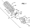
- FIG. 1 illustrates a suture anchor 10 according to the present invention.
- Suture anchor 10 comprises a distal body portion 12 which connects to a proximal body portion 14 both of which are held together by a pin 16 through respective cross-bores 18 and 20 in the distal body portion 12 and the proximal body portion 14.
- the distal body portion 12 is generally cylindrical in shape having a proximal end 22 through which the cross-bore 18 passes and a distal end 24 which tapers inwardly for easier insertion of the suture anchor 10 into a bone hole (not shown in FIG. 1 ).
- An external screw thread 26 encircles the distal body portion 12.
- the proximal body portion 14 is also generally cylindrical in shape and bears an external screw thread 28 which mates with the thread 26 to form a continuous threading about the suture anchor 10.
- An axial-bore 30 passes through the proximal body portion 14.
- a distal portion 32 thereof, has a larger diameter than a proximal portion 34 thereby creating an internal annual abutment 36.
- the proximal portion 34 has a hexagonal cross-section to accommodate a driving tool (not shown in FIG. 1 ).
- a driving tool not shown in FIG. 1 .
- the bore-distal portion 32 has a circular cross section and is sized to closely accommodate the body distal portion proximal end 22.
- a suture receiver 38 fits within the axial-bore distal portion 32 between the abutment 36 and the distal body portion proximal end 22. It has a circular cross-section and is sized to rotate freely about a longitudinal axis 40 of the suture anchor 10.
- Six axial suture bores 42A-F pass through the suture receiver 38.
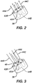
- the suture bores 42A-F accommodates three suture loops 44A-C.
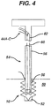
- a suture strand 46 can be woven through the suture bores 42A-F such that the suture loops 44A-C can be threaded through portions of the suture strand 46 extending above the suture receiver 38.
- Ends 48 of the each of the suture loops 44A-C extend proximally out of the suture anchor 10 through the axial bore 30.
- the suture ends 48 can then be attached to soft tissue as is understood by one of skill in the art for attaching that soft tissue to a bone.
- each of the suture loops 44A-C may extend through the rotator cuff tendon at different locations to effect a repair.
- the design of the suture anchor 10 provides advantages both in manufacturability and in performance. Having the suture loops 44A-C attach internal of the suture anchor and extending out through the axial bore 30, provides a preferred angle of exit toward soft tissue versus a proximal attachment point. With the separate distal body portion 12 and proximal body portion 14 attaching the suture loops 44A-C deep within the suture anchor 10 becomes easier during manufacturing. When inserting a conventional threaded anchor, any suture loops extending therefrom tend to twist due to the twisting of the anchor in its insertion. The present suture receiver 38 is free to rotate within the axial bore 30 thus reducing twisting of the suture loops 44A-C as the suture anchor 10 is inserted.
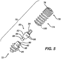
- the suture anchor 10 is inserted into a bone 50 having a pre-drilled hole 52.
- a driver 54 having an elongated body 56 and an external hex shape at its distal tip 58, mates with the hex shaped axial bore proximal portion 34.
- the suture loops 44A-C extend proximally out of the suture anchor 10 through a canulation 60 through the driver distal tip 58 and body 56.
- the canulation 60 is open 62 along one side much that after the suture anchor is driven into the bone hole 52 by the driver 54, the driver 54 can be removed from the suture anchor 10 with the suture loops 44A-C disengaging from the driver 54 through the canulation opening 62.
- FIG. 5 illustrates an alternative suture anchor 70 comprising a distal threaded body portion 72 and proximal threaded body portion 74.
- the suture anchor 70 is similar in most respects to the suture anchor 10.
- the proximal body portion 74 carries an additional thread start 76 at its proximal portion 78 thereby effectively increasing thread pitch at the proximal portion 78 and thus enhancing purchase within the hard cortical bone (not shown in FIG. 5 ) with which this portion typically engages.
- the anchor 70 employs a somewhat different suture receiver 80.
- the suture receiver 80 comprises a central cylindrical body 82 having a proximally extending suture eyelet 84.
- a distally extending post 86 terminates in an annular flange 88.
- the anchor distal body portion 72 has an axial bore 90 having a distal body portion 92 sized to accommodate the flange 88 and a narrower proximal portion 94 sized to accommodate the post 86 with the diameter differences creating an internal annular abutment 96 against which the flange 88 bears preventing its proximal movement out of the bore 90.
- a lateral cut out 98 is provided in the distal body portion 72 to allow the flange 88 and post 86 to be inserted laterally into distal bore 90. This arrangement allows the suture receiver 80 to rotate freely within the distal bore (90).
- bosses 98 extend outwardly radially from the suture receiver body 82 and fit closely, yet with rotation, within an axial bore 100 in the proximal body portion 74.
- Suture loops (not shown in FIG.5 ) can be passed through the eyelet 84 and also, if desired, around each of the bosses 98, and then proximally out of the anchor through the bore 100, the loops about the bosses being held by the bosses 98 and not being able to slip between the bosses 98 and the body 74 due to the close fit of the bosses 98 within the bore 100.
- FIG. 6 illustrates a further embodiment of a suture anchor 110 according to the invention similar to that shown in FIG. 5 .
- a suture receiver 112 is rotatably received within a distal body portion 114 as in the previous embodiment however its proximal end 116 is structured differently. It is cylindrical and bears three suture eyelets 118 A-C which are spaced apart both axially and rotationally, with the middle eyelet 118 B passing laterally through the proximal end 116 at 45 degrees with respect to the top eyelet 118 A and bottom eyelet 118 C and with the top and bottom eyelets 118 A and 118 C passing laterally through the proximal end and being oriented normal to each other.
- the placement and orientation of the eyelets 118 A-C assists in suture management, both in separation and in identification of individual loops.
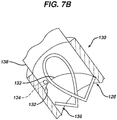
- FIGS. 7A-C illustrate a further suture anchor 120 having an alternative suture receiver 122 in the form of a bent loop 124 of spring metal having proximally extending ends 126. It is received within an axial bore 128 of a distal body portion 130 of the anchor 120 (which attaches to a proximal body portion 131). One or more lengths of suture (not shown in FIGS. 7A-C ) can attach to the loop 124. Proximal force therefrom draws the ends 126 up along a camming ledge 132 within the bore 128 toward angled side ports 134 from the bore 128 through the distal body portion 130, allowing the ends 126 to protrude from the distal body portion 130 (see FIG.
- a distal end 136 of a cannulated insertion tool 138 keep the ends 126 within the bore 128 and distal of the ports 134 while allowing rotation of the suture receiver 122 within the bore 128.
Landscapes
- Health & Medical Sciences (AREA)
- Surgery (AREA)
- Life Sciences & Earth Sciences (AREA)
- Biomedical Technology (AREA)
- Nuclear Medicine, Radiotherapy & Molecular Imaging (AREA)
- Engineering & Computer Science (AREA)
- Rheumatology (AREA)
- Heart & Thoracic Surgery (AREA)
- Medical Informatics (AREA)
- Molecular Biology (AREA)
- Animal Behavior & Ethology (AREA)
- General Health & Medical Sciences (AREA)
- Public Health (AREA)
- Veterinary Medicine (AREA)
- Surgical Instruments (AREA)
Description
- This invention relates to suture anchors for attaching suture to bone, and more specifically to such suture anchors which employ a suture management feature.
- It is known to use suture anchors for attaching soft tissues such as ligaments or tendons to adjacent bone. Threaded suture anchors employ external threads and are rotated into the bone, usually into a pre-drilled bone hole, to affix the suture anchor to the bone. They will typically employ an eyelet or other feature for affixing one or more sutures to the anchor. Managing the sutures extending from the suture anchor can be a challenge.
-
WO 02/11630 -
WO 02/21998 - A suture anchor according to the present invention comprises an anchor body having a longitudinal axis and bone engaging external threads oriented for rotation about the longitudinal axis. A suture attachment on the anchor body is rotational with respect to the body about the longitudinal axis whereby to help reduce twisting of one or more sutures which may be attached to the suture attachment as the anchor body is threaded into a bone. An axial bore enters the body from a proximal end thereof with the suture attachment located on the body such that one or more sutures attached thereto can extend out of the axial bore at the body proximal end. The suture attachment comprises a disc having a plurality of axial holes therethrough for receiving one or more loops of suture therethrough, or a cylinder bearing a plurality of suture eyelets that pass laterally through the cylinder and are spaced apart both axially and rotationally.
- Preferably, the body and suture attachment are provided sterile and packaged in a bacteria proof enclosure. One or more sutures can be attached to the suture attachment.
- Preferably, a loop of suture is affixed to the suture attachment, the loop having ends extending outwardly from the suture anchor body and suture attachment. Also preferably, a plurality of suture loops of suture are affixed to the suture attachment, each loop having ends extending outwardly from the suture anchor body and suture attachment.
- Preferably, the body comprises a first abutment surface within the axial bore and the suture attachment comprises an opposing second abutment surface engaged with the first abutment surface such that the suture attachment is rotatable in the axial bore against the first abutment surface with the engagement between the first abutment surface and the second abutment surface preventing the suture attachment from moving proximally out of the axial bore. Preferably, the first abutment surface and second abutment surface are annular.
- In one aspect of the invention, the suture attachment comprises a proximal cylindrical portion having one or more radially extending bosses thereon, the cylindrical portion being received within the axial bore with the one or more bosses adjacent a wall of the anchor body forming the axial bore such that suture looped about the one or more bosses is retained by the one or more bosses within the body between the wall and cylindrical portion.
-
-
FIG. 1 is an exploded perspective view of a suture anchor according to the present invention;FIG. 2 is a perspective view of a suture receiver of the suture anchor ofFIG. 1 ;FIG. 3 is a perspective view of the suture receiver ofFIG. 2 with an alternative method for engaging multiple suture loops;FIG. 4 is a cut-away view of the suture anchor ofFIG. 1 being implanted into a bone; -
FIG. 5 is an exploded perspective view of another suture anchor which does not form part of the invention; -
FIG. 6 is an exploded perspective view of a further embodiment of a suture anchor according to the present invention; -
FIG. 7A is a perspective view of another suture anchor which does not form part of the invention; -
FIG. 7B is an exploded perspective view of the distal portion of the suture anchor ofFIG. 7A; and FIG. 7C is a cut-away view of the distal portion of the suture anchor ofFIG. 7A . -
FIG. 1 illustrates asuture anchor 10 according to the present invention.Suture anchor 10 comprises adistal body portion 12 which connects to aproximal body portion 14 both of which are held together by apin 16 throughrespective cross-bores distal body portion 12 and theproximal body portion 14. Thedistal body portion 12 is generally cylindrical in shape having aproximal end 22 through which thecross-bore 18 passes and adistal end 24 which tapers inwardly for easier insertion of thesuture anchor 10 into a bone hole (not shown inFIG. 1 ). Anexternal screw thread 26 encircles thedistal body portion 12. - The
proximal body portion 14 is also generally cylindrical in shape and bears anexternal screw thread 28 which mates with thethread 26 to form a continuous threading about thesuture anchor 10. An axial-bore 30 passes through theproximal body portion 14. Adistal portion 32 thereof, has a larger diameter than aproximal portion 34 thereby creating an internalannual abutment 36. Theproximal portion 34 has a hexagonal cross-section to accommodate a driving tool (not shown inFIG. 1 ). One with ordinary skill in the art would appreciate that alternative tool/anchor engagements may be employed. - The bore-
distal portion 32 has a circular cross section and is sized to closely accommodate the body distal portionproximal end 22. Asuture receiver 38 fits within the axial-boredistal portion 32 between theabutment 36 and the distal body portionproximal end 22. It has a circular cross-section and is sized to rotate freely about alongitudinal axis 40 of thesuture anchor 10. Six axial suture bores 42A-F pass through thesuture receiver 38. - Turning also now to
FIG. 2 , the suture bores 42A-F accommodates threesuture loops 44A-C. Alternatively, as shown inFIG. 3 , asuture strand 46 can be woven through thesuture bores 42A-F such that thesuture loops 44A-C can be threaded through portions of thesuture strand 46 extending above thesuture receiver 38. Ends 48 of the each of thesuture loops 44A-C extend proximally out of thesuture anchor 10 through theaxial bore 30. The suture ends 48 can then be attached to soft tissue as is understood by one of skill in the art for attaching that soft tissue to a bone. For instance, in a rotator cuff repair, each of thesuture loops 44A-C may extend through the rotator cuff tendon at different locations to effect a repair. - The design of the
suture anchor 10 provides advantages both in manufacturability and in performance. Having thesuture loops 44A-C attach internal of the suture anchor and extending out through theaxial bore 30, provides a preferred angle of exit toward soft tissue versus a proximal attachment point. With the separatedistal body portion 12 andproximal body portion 14 attaching thesuture loops 44A-C deep within thesuture anchor 10 becomes easier during manufacturing. When inserting a conventional threaded anchor, any suture loops extending therefrom tend to twist due to the twisting of the anchor in its insertion. Thepresent suture receiver 38 is free to rotate within theaxial bore 30 thus reducing twisting of thesuture loops 44A-C as thesuture anchor 10 is inserted. - Turning also now to
FIG. 4 , preferably, thesuture anchor 10 is inserted into abone 50 having apre-drilled hole 52. Adriver 54 having anelongated body 56 and an external hex shape at itsdistal tip 58, mates with the hex shaped axial boreproximal portion 34. Thesuture loops 44A-C extend proximally out of thesuture anchor 10 through acanulation 60 through the driverdistal tip 58 andbody 56. In one preferred embodiment, thecanulation 60 is open 62 along one side much that after the suture anchor is driven into thebone hole 52 by thedriver 54, thedriver 54 can be removed from thesuture anchor 10 with thesuture loops 44A-C disengaging from thedriver 54 through thecanulation opening 62. -
FIG. 5 illustrates analternative suture anchor 70 comprising a distal threadedbody portion 72 and proximal threaded body portion 74. Thesuture anchor 70 is similar in most respects to thesuture anchor 10. However, the proximal body portion 74 carries anadditional thread start 76 at itsproximal portion 78 thereby effectively increasing thread pitch at theproximal portion 78 and thus enhancing purchase within the hard cortical bone (not shown inFIG. 5 ) with which this portion typically engages. Also, theanchor 70 employs a somewhatdifferent suture receiver 80. - The
suture receiver 80 comprises a centralcylindrical body 82 having a proximally extendingsuture eyelet 84. Adistally extending post 86 terminates in anannular flange 88. The anchordistal body portion 72 has anaxial bore 90 having adistal body portion 92 sized to accommodate theflange 88 and a narrowerproximal portion 94 sized to accommodate thepost 86 with the diameter differences creating an internal annular abutment 96 against which theflange 88 bears preventing its proximal movement out of thebore 90. A lateral cut out 98 is provided in thedistal body portion 72 to allow theflange 88 and post 86 to be inserted laterally intodistal bore 90. This arrangement allows thesuture receiver 80 to rotate freely within the distal bore (90). -
Several bosses 98 extend outwardly radially from thesuture receiver body 82 and fit closely, yet with rotation, within anaxial bore 100 in the proximal body portion 74. Suture loops (not shown inFIG.5 ) can be passed through theeyelet 84 and also, if desired, around each of thebosses 98, and then proximally out of the anchor through thebore 100, the loops about the bosses being held by thebosses 98 and not being able to slip between thebosses 98 and the body 74 due to the close fit of thebosses 98 within thebore 100. -
FIG. 6 illustrates a further embodiment of a suture anchor 110 according to the invention similar to that shown inFIG. 5 . Asuture receiver 112 is rotatably received within adistal body portion 114 as in the previous embodiment however itsproximal end 116 is structured differently. It is cylindrical and bears three suture eyelets 118 A-C which are spaced apart both axially and rotationally, with themiddle eyelet 118 B passing laterally through theproximal end 116 at 45 degrees with respect to thetop eyelet 118 A andbottom eyelet 118 C and with the top andbottom eyelets -
FIGS. 7A-C . illustrate afurther suture anchor 120 having analternative suture receiver 122 in the form of abent loop 124 of spring metal having proximally extending ends 126. It is received within anaxial bore 128 of adistal body portion 130 of the anchor 120 (which attaches to a proximal body portion 131). One or more lengths of suture (not shown inFIGS. 7A-C ) can attach to theloop 124. Proximal force therefrom draws theends 126 up along acamming ledge 132 within thebore 128 towardangled side ports 134 from thebore 128 through thedistal body portion 130, allowing theends 126 to protrude from the distal body portion 130 (seeFIG. 7 C) and provide additional fixation within a bone (not shown inFIGS. 7A-C ). While theanchor 120 is being inserted adistal end 136 of a cannulatedinsertion tool 138 keep theends 126 within thebore 128 and distal of theports 134 while allowing rotation of thesuture receiver 122 within thebore 128.
Claims (7)
- A suture anchor (10; 110) comprising:an anchor body (12, 14; 114) comprising a longitudinal axis, bone engaging external threads (26, 28) oriented for rotation about the longitudinal axis and an axial bore (30) entering the body from a proximal end (14) thereof; anda suture attachment (38; 112) located on the anchor body such that one or more sutures (44A-C) attached thereto can extend out of the axial bore at the body proximal end, the suture attachment being rotational with respect to the body about the longitudinal axis whereby to help reduce twisting of one or more sutures which may be attached to the suture attachment as the anchor body is threaded into a bone;characterized in that the suture attachment comprises a disc (38) having a plurality of axial holes (42A-F) through it for receiving one or more loops of suture (44A-C), or a cylinder (116) bearing a plurality of suture eyelets (118A-C) that pass laterally through the cylinder and are spaced apart both axially and rotationally.
- The suture anchor of claim 1 wherein the body and suture attachment are sterile and packaged in a bacteria proof enclosure.
- The suture anchor of claim 1 wherein at least one suture (44A-C) is attached to the suture attachment.
- The suture anchor of claim 3 wherein the at least one suture comprises a loop of suture affixed to the suture attachment, the loop having ends (48) extending outwardly from the suture anchor body and suture attachment.
- The suture anchor of claim 3 wherein the at least one suture comprises a plurality of suture loops (44A-C) of suture affixed to the suture attachment, each loop having ends extending outwardly from the suture anchor body and suture attachment.
- The suture anchor of claim 1 wherein the body comprises a first abutment surface (36; 96) within the axial bore and wherein the suture attachment comprises an opposing second abutment surface (88) engaged with the first abutment surface such that the suture attachment is rotatable in the axial bore against the first abutment surface and the engagement between the first abutment surface and the second abutment surface prevents the suture attachment from moving proximally out of the axial bore.
- The suture anchor of claim 6 wherein the first abutment surface and second abutment surface are annular.
Applications Claiming Priority (1)
| Application Number | Priority Date | Filing Date | Title |
|---|---|---|---|
| US38802810P | 2010-09-30 | 2010-09-30 |
Publications (3)
| Publication Number | Publication Date |
|---|---|
| EP2436316A1 EP2436316A1 (en) | 2012-04-04 |
| EP2436316B1 true EP2436316B1 (en) | 2018-03-21 |
| EP2436316B8 EP2436316B8 (en) | 2018-05-23 |
Family
ID=44677765
Family Applications (1)
| Application Number | Title | Priority Date | Filing Date |
|---|---|---|---|
| EP11183317.4A Not-in-force EP2436316B8 (en) | 2010-09-30 | 2011-09-29 | Suture anchor with suture management |
Country Status (6)
| Country | Link |
|---|---|
| US (1) | US20120083841A1 (en) |
| EP (1) | EP2436316B8 (en) |
| JP (1) | JP5959820B2 (en) |
| CN (1) | CN102614000B (en) |
| AU (3) | AU2011226897A1 (en) |
| CA (1) | CA2754260A1 (en) |
Families Citing this family (12)
| Publication number | Priority date | Publication date | Assignee | Title |
|---|---|---|---|---|
| US20090281581A1 (en) | 2008-05-06 | 2009-11-12 | Berg Jeffery H | Method and device for securing sutures to bones |
| US8932354B2 (en) * | 2009-04-17 | 2015-01-13 | Shane Barwood | Tenodesis fixation method |
| US9861353B2 (en) | 2012-08-03 | 2018-01-09 | Stabilynx, Inc. | Devices, systems, and methods for attaching soft tissue to bone tissue |
| WO2014022838A1 (en) * | 2012-08-03 | 2014-02-06 | Lindenwood Medical. Inc. | Suture anchor device and methods of use |
| US20150272567A1 (en) | 2012-08-03 | 2015-10-01 | Stabilynx, Inc. | Devices, systems, and methods for attaching soft tissue to bone tissue |
| WO2016154406A1 (en) * | 2015-03-24 | 2016-09-29 | Smith & Nephew, Inc. | Bone anchor system having movable medial eyelet |
| US10617406B2 (en) * | 2015-06-30 | 2020-04-14 | Smith & Nephew, Inc. | Suture anchor system with threaded plug |
| CN107095697B (en) * | 2017-05-12 | 2024-02-06 | 上海利格泰生物科技股份有限公司 | Flat suture anchor |
| WO2019123116A1 (en) * | 2017-12-20 | 2019-06-27 | Peach Dian Samuel | A medical anchor |
| CN112971871B (en) * | 2019-12-17 | 2023-01-03 | 先健科技(深圳)有限公司 | Adjustable bent sheath tube |
| WO2024163999A1 (en) * | 2023-02-03 | 2024-08-08 | Paragon 28, Inc. | Dynamic syndesmosis implant systems and methods |
| US20250072884A1 (en) * | 2023-09-05 | 2025-03-06 | Biomet Manufacturing, Llc | Lateral row anchor |
Family Cites Families (15)
| Publication number | Priority date | Publication date | Assignee | Title |
|---|---|---|---|---|
| US5152790A (en) * | 1991-03-21 | 1992-10-06 | American Cyanamid Company | Ligament reconstruction graft anchor apparatus |
| US5486197A (en) * | 1994-03-24 | 1996-01-23 | Ethicon, Inc. | Two-piece suture anchor with barbs |
| US9521999B2 (en) * | 2005-09-13 | 2016-12-20 | Arthrex, Inc. | Fully-threaded bioabsorbable suture anchor |
| US6517542B1 (en) * | 1999-08-04 | 2003-02-11 | The Cleveland Clinic Foundation | Bone anchoring system |
| AU2001292668A1 (en) * | 2000-09-12 | 2002-03-26 | Axya Medical, Inc. | Apparatus and method for securing suture to bone |
| US6923824B2 (en) * | 2000-09-12 | 2005-08-02 | Axya Medical, Inc. | Apparatus and method for securing suture to bone |
| ES2378608T3 (en) * | 2000-12-22 | 2012-04-16 | Tyco Healthcare Group Lp | Suture screw |
| US20020173822A1 (en) * | 2001-05-17 | 2002-11-21 | Justin Daniel F. | Threaded suture anchor |
| US20060282081A1 (en) * | 2004-04-16 | 2006-12-14 | Fanton Gary S | Apparatus and method for securing tissue to bone with a suture |
| US7645293B2 (en) * | 2004-04-21 | 2010-01-12 | United States Surgical Corporation | Suture anchor installation system and method |
| US8986345B2 (en) * | 2004-12-07 | 2015-03-24 | Biomet Sports Medicine, Llc | Expanding suture anchor having an actuator pin |
| CA2600279A1 (en) * | 2005-03-10 | 2006-09-21 | Tyco Healthcare Group Lp | Suture anchors |
| JP4885979B2 (en) * | 2005-12-22 | 2012-02-29 | エス.ウェスト ジュニア ヒュー | Bone anchor used to attach soft tissue to bone |
| EP1996084A1 (en) * | 2006-03-22 | 2008-12-03 | Sapphire Medical, Inc. | Suture passer devices and uses thereof |
| US20100049249A1 (en) * | 2008-08-25 | 2010-02-25 | Linvatec Corporation | Suture anchor extension |
-
2011
- 2011-09-23 US US13/241,781 patent/US20120083841A1/en not_active Abandoned
- 2011-09-27 AU AU2011226897A patent/AU2011226897A1/en not_active Abandoned
- 2011-09-29 JP JP2011214323A patent/JP5959820B2/en not_active Expired - Fee Related
- 2011-09-29 CA CA2754260A patent/CA2754260A1/en not_active Abandoned
- 2011-09-29 EP EP11183317.4A patent/EP2436316B8/en not_active Not-in-force
- 2011-09-30 CN CN201110310184.8A patent/CN102614000B/en not_active Expired - Fee Related
-
2016
- 2016-04-06 AU AU2016202137A patent/AU2016202137A1/en not_active Abandoned
-
2018
- 2018-06-05 AU AU2018203962A patent/AU2018203962B2/en not_active Ceased
Non-Patent Citations (1)
| Title |
|---|
| None * |
Also Published As
| Publication number | Publication date |
|---|---|
| AU2016202137A1 (en) | 2016-04-28 |
| AU2011226897A1 (en) | 2012-04-19 |
| CN102614000A (en) | 2012-08-01 |
| CA2754260A1 (en) | 2012-03-30 |
| EP2436316B8 (en) | 2018-05-23 |
| US20120083841A1 (en) | 2012-04-05 |
| AU2018203962B2 (en) | 2019-03-14 |
| CN102614000B (en) | 2016-08-03 |
| JP2012075889A (en) | 2012-04-19 |
| EP2436316A1 (en) | 2012-04-04 |
| JP5959820B2 (en) | 2016-08-02 |
| AU2018203962A1 (en) | 2018-06-21 |
Similar Documents
| Publication | Publication Date | Title |
|---|---|---|
| AU2018203962B2 (en) | Suture anchor with suture management | |
| US20120083840A1 (en) | Suture anchor with enhanced fixation | |
| US11576664B2 (en) | Methods for anchoring suture to bone | |
| JP4885979B2 (en) | Bone anchor used to attach soft tissue to bone | |
| US8414613B2 (en) | Medical device and procedure for attaching tissue to bone | |
| US7322978B2 (en) | Bone anchors for use in attaching soft tissue to a bone | |
| US7442202B2 (en) | Suture anchor attached to tissue-fixation disk without top knot | |
| CA2639507C (en) | Dual thread cannulated suture anchor | |
| US5868789A (en) | Removable suture anchor apparatus | |
| US8523903B2 (en) | Partial thickness rotator cuff repair system and method | |
| US20100179573A1 (en) | Medical device and procedure for attaching tissue to bone | |
| US20120041484A1 (en) | Medical device and procedure for attaching tissue to bone | |
| US20100331896A1 (en) | Device for Anchoring a Tissue in a Bone | |
| EP1797828B1 (en) | Threaded suture anchor with starting pitch | |
| US20100262186A1 (en) | Twist-in suture anchor | |
| US7156864B2 (en) | Suture anchor | |
| WO2004062507A2 (en) | Fixation device for use in surgery | |
| AU2014250694B2 (en) | Dual thread cannulated suture anchor |
Legal Events
| Date | Code | Title | Description |
|---|---|---|---|
| PUAI | Public reference made under article 153(3) epc to a published international application that has entered the european phase |
Free format text: ORIGINAL CODE: 0009012 |
|
| AK | Designated contracting states |
Kind code of ref document: A1 Designated state(s): AL AT BE BG CH CY CZ DE DK EE ES FI FR GB GR HR HU IE IS IT LI LT LU LV MC MK MT NL NO PL PT RO RS SE SI SK SM TR |
|
| AX | Request for extension of the european patent |
Extension state: BA ME |
|
| 17P | Request for examination filed |
Effective date: 20121004 |
|
| 17Q | First examination report despatched |
Effective date: 20170102 |
|
| GRAJ | Information related to disapproval of communication of intention to grant by the applicant or resumption of examination proceedings by the epo deleted |
Free format text: ORIGINAL CODE: EPIDOSDIGR1 |
|
| GRAP | Despatch of communication of intention to grant a patent |
Free format text: ORIGINAL CODE: EPIDOSNIGR1 |
|
| INTG | Intention to grant announced |
Effective date: 20171129 |
|
| GRAS | Grant fee paid |
Free format text: ORIGINAL CODE: EPIDOSNIGR3 |
|
| GRAA | (expected) grant |
Free format text: ORIGINAL CODE: 0009210 |
|
| AK | Designated contracting states |
Kind code of ref document: B1 Designated state(s): AL AT BE BG CH CY CZ DE DK EE ES FI FR GB GR HR HU IE IS IT LI LT LU LV MC MK MT NL NO PL PT RO RS SE SI SK SM TR |
|
| REG | Reference to a national code |
Ref country code: GB Ref legal event code: FG4D |
|
| REG | Reference to a national code |
Ref country code: CH Ref legal event code: EP Ref country code: CH Ref legal event code: NV Representative=s name: E. BLUM AND CO. AG PATENT- UND MARKENANWAELTE , CH |
|
| REG | Reference to a national code |
Ref country code: AT Ref legal event code: REF Ref document number: 980229 Country of ref document: AT Kind code of ref document: T Effective date: 20180415 |
|
| REG | Reference to a national code |
Ref country code: IE Ref legal event code: FG4D |
|
| REG | Reference to a national code |
Ref country code: DE Ref legal event code: R096 Ref document number: 602011046638 Country of ref document: DE |
|
| RAP2 | Party data changed (patent owner data changed or rights of a patent transferred) |
Owner name: DEPUY MITEK, LLC |
|
| REG | Reference to a national code |
Ref country code: CH Ref legal event code: PFA Owner name: DEPUY MITEK, LLC, US Free format text: FORMER OWNER: DEPUY MITEK, INC., US |
|
| REG | Reference to a national code |
Ref country code: DE Ref legal event code: R082 Ref document number: 602011046638 Country of ref document: DE Representative=s name: MUELLER-BORE & PARTNER PATENTANWAELTE PARTG MB, DE Ref country code: DE Ref legal event code: R081 Ref document number: 602011046638 Country of ref document: DE Owner name: DEPUY MITEK, LLC, RAYNHAM, US Free format text: FORMER OWNER: DEPUY MITEK,INC., RAYNHAM, MASS., US |
|
| REG | Reference to a national code |
Ref country code: NL Ref legal event code: MP Effective date: 20180321 |
|
| PG25 | Lapsed in a contracting state [announced via postgrant information from national office to epo] |
Ref country code: NO Free format text: LAPSE BECAUSE OF FAILURE TO SUBMIT A TRANSLATION OF THE DESCRIPTION OR TO PAY THE FEE WITHIN THE PRESCRIBED TIME-LIMIT Effective date: 20180621 Ref country code: FI Free format text: LAPSE BECAUSE OF FAILURE TO SUBMIT A TRANSLATION OF THE DESCRIPTION OR TO PAY THE FEE WITHIN THE PRESCRIBED TIME-LIMIT Effective date: 20180321 Ref country code: LT Free format text: LAPSE BECAUSE OF FAILURE TO SUBMIT A TRANSLATION OF THE DESCRIPTION OR TO PAY THE FEE WITHIN THE PRESCRIBED TIME-LIMIT Effective date: 20180321 Ref country code: HR Free format text: LAPSE BECAUSE OF FAILURE TO SUBMIT A TRANSLATION OF THE DESCRIPTION OR TO PAY THE FEE WITHIN THE PRESCRIBED TIME-LIMIT Effective date: 20180321 Ref country code: CY Free format text: LAPSE BECAUSE OF FAILURE TO SUBMIT A TRANSLATION OF THE DESCRIPTION OR TO PAY THE FEE WITHIN THE PRESCRIBED TIME-LIMIT Effective date: 20180321 |
|
| REG | Reference to a national code |
Ref country code: LT Ref legal event code: MG4D |
|
| REG | Reference to a national code |
Ref country code: FR Ref legal event code: PLFP Year of fee payment: 8 |
|
| REG | Reference to a national code |
Ref country code: AT Ref legal event code: MK05 Ref document number: 980229 Country of ref document: AT Kind code of ref document: T Effective date: 20180321 |
|
| PG25 | Lapsed in a contracting state [announced via postgrant information from national office to epo] |
Ref country code: RS Free format text: LAPSE BECAUSE OF FAILURE TO SUBMIT A TRANSLATION OF THE DESCRIPTION OR TO PAY THE FEE WITHIN THE PRESCRIBED TIME-LIMIT Effective date: 20180321 Ref country code: BG Free format text: LAPSE BECAUSE OF FAILURE TO SUBMIT A TRANSLATION OF THE DESCRIPTION OR TO PAY THE FEE WITHIN THE PRESCRIBED TIME-LIMIT Effective date: 20180621 Ref country code: LV Free format text: LAPSE BECAUSE OF FAILURE TO SUBMIT A TRANSLATION OF THE DESCRIPTION OR TO PAY THE FEE WITHIN THE PRESCRIBED TIME-LIMIT Effective date: 20180321 Ref country code: GR Free format text: LAPSE BECAUSE OF FAILURE TO SUBMIT A TRANSLATION OF THE DESCRIPTION OR TO PAY THE FEE WITHIN THE PRESCRIBED TIME-LIMIT Effective date: 20180622 Ref country code: SE Free format text: LAPSE BECAUSE OF FAILURE TO SUBMIT A TRANSLATION OF THE DESCRIPTION OR TO PAY THE FEE WITHIN THE PRESCRIBED TIME-LIMIT Effective date: 20180321 |
|
| PG25 | Lapsed in a contracting state [announced via postgrant information from national office to epo] |
Ref country code: ES Free format text: LAPSE BECAUSE OF FAILURE TO SUBMIT A TRANSLATION OF THE DESCRIPTION OR TO PAY THE FEE WITHIN THE PRESCRIBED TIME-LIMIT Effective date: 20180321 Ref country code: NL Free format text: LAPSE BECAUSE OF FAILURE TO SUBMIT A TRANSLATION OF THE DESCRIPTION OR TO PAY THE FEE WITHIN THE PRESCRIBED TIME-LIMIT Effective date: 20180321 Ref country code: AL Free format text: LAPSE BECAUSE OF FAILURE TO SUBMIT A TRANSLATION OF THE DESCRIPTION OR TO PAY THE FEE WITHIN THE PRESCRIBED TIME-LIMIT Effective date: 20180321 Ref country code: EE Free format text: LAPSE BECAUSE OF FAILURE TO SUBMIT A TRANSLATION OF THE DESCRIPTION OR TO PAY THE FEE WITHIN THE PRESCRIBED TIME-LIMIT Effective date: 20180321 Ref country code: RO Free format text: LAPSE BECAUSE OF FAILURE TO SUBMIT A TRANSLATION OF THE DESCRIPTION OR TO PAY THE FEE WITHIN THE PRESCRIBED TIME-LIMIT Effective date: 20180321 Ref country code: PL Free format text: LAPSE BECAUSE OF FAILURE TO SUBMIT A TRANSLATION OF THE DESCRIPTION OR TO PAY THE FEE WITHIN THE PRESCRIBED TIME-LIMIT Effective date: 20180321 |
|
| PG25 | Lapsed in a contracting state [announced via postgrant information from national office to epo] |
Ref country code: SK Free format text: LAPSE BECAUSE OF FAILURE TO SUBMIT A TRANSLATION OF THE DESCRIPTION OR TO PAY THE FEE WITHIN THE PRESCRIBED TIME-LIMIT Effective date: 20180321 Ref country code: CZ Free format text: LAPSE BECAUSE OF FAILURE TO SUBMIT A TRANSLATION OF THE DESCRIPTION OR TO PAY THE FEE WITHIN THE PRESCRIBED TIME-LIMIT Effective date: 20180321 Ref country code: AT Free format text: LAPSE BECAUSE OF FAILURE TO SUBMIT A TRANSLATION OF THE DESCRIPTION OR TO PAY THE FEE WITHIN THE PRESCRIBED TIME-LIMIT Effective date: 20180321 Ref country code: SM Free format text: LAPSE BECAUSE OF FAILURE TO SUBMIT A TRANSLATION OF THE DESCRIPTION OR TO PAY THE FEE WITHIN THE PRESCRIBED TIME-LIMIT Effective date: 20180321 |
|
| PG25 | Lapsed in a contracting state [announced via postgrant information from national office to epo] |
Ref country code: PT Free format text: LAPSE BECAUSE OF FAILURE TO SUBMIT A TRANSLATION OF THE DESCRIPTION OR TO PAY THE FEE WITHIN THE PRESCRIBED TIME-LIMIT Effective date: 20180723 |
|
| REG | Reference to a national code |
Ref country code: DE Ref legal event code: R097 Ref document number: 602011046638 Country of ref document: DE |
|
| PLBE | No opposition filed within time limit |
Free format text: ORIGINAL CODE: 0009261 |
|
| STAA | Information on the status of an ep patent application or granted ep patent |
Free format text: STATUS: NO OPPOSITION FILED WITHIN TIME LIMIT |
|
| PG25 | Lapsed in a contracting state [announced via postgrant information from national office to epo] |
Ref country code: DK Free format text: LAPSE BECAUSE OF FAILURE TO SUBMIT A TRANSLATION OF THE DESCRIPTION OR TO PAY THE FEE WITHIN THE PRESCRIBED TIME-LIMIT Effective date: 20180321 |
|
| 26N | No opposition filed |
Effective date: 20190102 |
|
| PG25 | Lapsed in a contracting state [announced via postgrant information from national office to epo] |
Ref country code: MC Free format text: LAPSE BECAUSE OF FAILURE TO SUBMIT A TRANSLATION OF THE DESCRIPTION OR TO PAY THE FEE WITHIN THE PRESCRIBED TIME-LIMIT Effective date: 20180321 |
|
| PG25 | Lapsed in a contracting state [announced via postgrant information from national office to epo] |
Ref country code: SI Free format text: LAPSE BECAUSE OF FAILURE TO SUBMIT A TRANSLATION OF THE DESCRIPTION OR TO PAY THE FEE WITHIN THE PRESCRIBED TIME-LIMIT Effective date: 20180321 |
|
| REG | Reference to a national code |
Ref country code: BE Ref legal event code: MM Effective date: 20180930 |
|
| REG | Reference to a national code |
Ref country code: IE Ref legal event code: MM4A |
|
| PG25 | Lapsed in a contracting state [announced via postgrant information from national office to epo] |
Ref country code: LU Free format text: LAPSE BECAUSE OF NON-PAYMENT OF DUE FEES Effective date: 20180929 |
|
| PG25 | Lapsed in a contracting state [announced via postgrant information from national office to epo] |
Ref country code: IE Free format text: LAPSE BECAUSE OF NON-PAYMENT OF DUE FEES Effective date: 20180929 |
|
| PG25 | Lapsed in a contracting state [announced via postgrant information from national office to epo] |
Ref country code: BE Free format text: LAPSE BECAUSE OF NON-PAYMENT OF DUE FEES Effective date: 20180930 |
|
| PGFP | Annual fee paid to national office [announced via postgrant information from national office to epo] |
Ref country code: DE Payment date: 20190917 Year of fee payment: 9 Ref country code: IT Payment date: 20190917 Year of fee payment: 9 Ref country code: FR Payment date: 20190815 Year of fee payment: 9 |
|
| PGFP | Annual fee paid to national office [announced via postgrant information from national office to epo] |
Ref country code: GB Payment date: 20190926 Year of fee payment: 9 |
|
| PG25 | Lapsed in a contracting state [announced via postgrant information from national office to epo] |
Ref country code: MT Free format text: LAPSE BECAUSE OF NON-PAYMENT OF DUE FEES Effective date: 20180929 |
|
| PGFP | Annual fee paid to national office [announced via postgrant information from national office to epo] |
Ref country code: CH Payment date: 20190913 Year of fee payment: 9 |
|
| PG25 | Lapsed in a contracting state [announced via postgrant information from national office to epo] |
Ref country code: TR Free format text: LAPSE BECAUSE OF FAILURE TO SUBMIT A TRANSLATION OF THE DESCRIPTION OR TO PAY THE FEE WITHIN THE PRESCRIBED TIME-LIMIT Effective date: 20180321 |
|
| PG25 | Lapsed in a contracting state [announced via postgrant information from national office to epo] |
Ref country code: HU Free format text: LAPSE BECAUSE OF FAILURE TO SUBMIT A TRANSLATION OF THE DESCRIPTION OR TO PAY THE FEE WITHIN THE PRESCRIBED TIME-LIMIT; INVALID AB INITIO Effective date: 20110929 |
|
| PG25 | Lapsed in a contracting state [announced via postgrant information from national office to epo] |
Ref country code: MK Free format text: LAPSE BECAUSE OF NON-PAYMENT OF DUE FEES Effective date: 20180321 |
|
| PG25 | Lapsed in a contracting state [announced via postgrant information from national office to epo] |
Ref country code: IS Free format text: LAPSE BECAUSE OF FAILURE TO SUBMIT A TRANSLATION OF THE DESCRIPTION OR TO PAY THE FEE WITHIN THE PRESCRIBED TIME-LIMIT Effective date: 20180721 |
|
| REG | Reference to a national code |
Ref country code: DE Ref legal event code: R119 Ref document number: 602011046638 Country of ref document: DE |
|
| REG | Reference to a national code |
Ref country code: CH Ref legal event code: PL |
|
| GBPC | Gb: european patent ceased through non-payment of renewal fee |
Effective date: 20200929 |
|
| PG25 | Lapsed in a contracting state [announced via postgrant information from national office to epo] |
Ref country code: DE Free format text: LAPSE BECAUSE OF NON-PAYMENT OF DUE FEES Effective date: 20210401 Ref country code: FR Free format text: LAPSE BECAUSE OF NON-PAYMENT OF DUE FEES Effective date: 20200930 |
|
| PG25 | Lapsed in a contracting state [announced via postgrant information from national office to epo] |
Ref country code: LI Free format text: LAPSE BECAUSE OF NON-PAYMENT OF DUE FEES Effective date: 20200930 Ref country code: GB Free format text: LAPSE BECAUSE OF NON-PAYMENT OF DUE FEES Effective date: 20200929 Ref country code: CH Free format text: LAPSE BECAUSE OF NON-PAYMENT OF DUE FEES Effective date: 20200930 |
|
| PG25 | Lapsed in a contracting state [announced via postgrant information from national office to epo] |
Ref country code: IT Free format text: LAPSE BECAUSE OF NON-PAYMENT OF DUE FEES Effective date: 20200929 |