EP2436111B1 - Entstörfilter für einen gleichstrommotor - Google Patents
Entstörfilter für einen gleichstrommotor Download PDFInfo
- Publication number
- EP2436111B1 EP2436111B1 EP10712413A EP10712413A EP2436111B1 EP 2436111 B1 EP2436111 B1 EP 2436111B1 EP 10712413 A EP10712413 A EP 10712413A EP 10712413 A EP10712413 A EP 10712413A EP 2436111 B1 EP2436111 B1 EP 2436111B1
- Authority
- EP
- European Patent Office
- Prior art keywords
- motor
- drive signal
- interference
- frequency
- signal
- Prior art date
- Legal status (The legal status is an assumption and is not a legal conclusion. Google has not performed a legal analysis and makes no representation as to the accuracy of the status listed.)
- Not-in-force
Links
- 239000003990 capacitor Substances 0.000 claims description 36
- 238000005259 measurement Methods 0.000 claims description 32
- 238000000034 method Methods 0.000 claims description 12
- 238000004804 winding Methods 0.000 claims description 11
- 230000000737 periodic effect Effects 0.000 claims description 2
- 238000010079 rubber tapping Methods 0.000 claims 1
- 230000001629 suppression Effects 0.000 description 10
- 230000008878 coupling Effects 0.000 description 8
- 238000010168 coupling process Methods 0.000 description 8
- 238000005859 coupling reaction Methods 0.000 description 8
- 238000001514 detection method Methods 0.000 description 5
- 238000010408 sweeping Methods 0.000 description 3
- 230000002238 attenuated effect Effects 0.000 description 2
- 230000001939 inductive effect Effects 0.000 description 2
- 230000015572 biosynthetic process Effects 0.000 description 1
- 238000007796 conventional method Methods 0.000 description 1
- 230000001419 dependent effect Effects 0.000 description 1
- 238000011156 evaluation Methods 0.000 description 1
- 238000009499 grossing Methods 0.000 description 1
- 230000010363 phase shift Effects 0.000 description 1
Images


Classifications
-
- H—ELECTRICITY
- H02—GENERATION; CONVERSION OR DISTRIBUTION OF ELECTRIC POWER
- H02P—CONTROL OR REGULATION OF ELECTRIC MOTORS, ELECTRIC GENERATORS OR DYNAMO-ELECTRIC CONVERTERS; CONTROLLING TRANSFORMERS, REACTORS OR CHOKE COILS
- H02P7/00—Arrangements for regulating or controlling the speed or torque of electric DC motors
- H02P7/06—Arrangements for regulating or controlling the speed or torque of electric DC motors for regulating or controlling an individual DC dynamo-electric motor by varying field or armature current
- H02P7/18—Arrangements for regulating or controlling the speed or torque of electric DC motors for regulating or controlling an individual DC dynamo-electric motor by varying field or armature current by master control with auxiliary power
- H02P7/24—Arrangements for regulating or controlling the speed or torque of electric DC motors for regulating or controlling an individual DC dynamo-electric motor by varying field or armature current by master control with auxiliary power using discharge tubes or semiconductor devices
- H02P7/28—Arrangements for regulating or controlling the speed or torque of electric DC motors for regulating or controlling an individual DC dynamo-electric motor by varying field or armature current by master control with auxiliary power using discharge tubes or semiconductor devices using semiconductor devices
- H02P7/285—Arrangements for regulating or controlling the speed or torque of electric DC motors for regulating or controlling an individual DC dynamo-electric motor by varying field or armature current by master control with auxiliary power using discharge tubes or semiconductor devices using semiconductor devices controlling armature supply only
-
- G—PHYSICS
- G01—MEASURING; TESTING
- G01P—MEASURING LINEAR OR ANGULAR SPEED, ACCELERATION, DECELERATION, OR SHOCK; INDICATING PRESENCE, ABSENCE, OR DIRECTION, OF MOVEMENT
- G01P3/00—Measuring linear or angular speed; Measuring differences of linear or angular speeds
- G01P3/42—Devices characterised by the use of electric or magnetic means
- G01P3/44—Devices characterised by the use of electric or magnetic means for measuring angular speed
- G01P3/48—Devices characterised by the use of electric or magnetic means for measuring angular speed by measuring frequency of generated current or voltage
-
- H—ELECTRICITY
- H02—GENERATION; CONVERSION OR DISTRIBUTION OF ELECTRIC POWER
- H02P—CONTROL OR REGULATION OF ELECTRIC MOTORS, ELECTRIC GENERATORS OR DYNAMO-ELECTRIC CONVERTERS; CONTROLLING TRANSFORMERS, REACTORS OR CHOKE COILS
- H02P29/00—Arrangements for regulating or controlling electric motors, appropriate for both AC and DC motors
- H02P29/50—Reduction of harmonics
Definitions
- the present invention relates to a DC motor system and a method for determining the speed and / or the angle of rotation of a DC motor, in particular a DC motor system according to the invention.
- sensors for detecting information about the operating state of a rotary electric motor, in particular about the speed of a DC motor
- a variety of methods are known. For example, sensors, in particular position sensors are used, which cooperate with a detector which determines this information from the position of the rotor and / or from the change in the position of the rotor. Or the windings of the DC motor are driven by a current, and from fluctuations in the current intensity is closed to the speed. Also from the course of current consumption when sweeping the commutator can be concluded that there is a change between the commutator bars to determine the speed of the electric motor.
- These conventional methods require additional sensors or sophisticated filters, which are sometimes difficult to tune. In addition, a determination of the rotational angle of the rotor is difficult, inaccurate or impossible with these methods.
- gas discharges occur between the commutator bars and the brushes sweeping the commutator bars, particularly when a brush passes from one to the next commutator bar, which manifests itself in current spikes and causes high frequency spurious emissions. And even with rapid power changes, for example, when switching on and off electrical loads, arise in the range of a very wide frequency band electromagnetic harmonics.
- the formation of such interference is reduced by limiting the increase in current, or there are provided noise filters that filter the signals on the supply lines to and from the source of interference.
- Such a suppression device shows, for example, the document DE 10 2005 011 293 A1 , which allows not only the commutator suppression but also a Abschaltspannugsimpuls- limitation.
- the interference suppression device has, for commutator interference suppression in the electrical path of at least one connecting line, a pass-through capacitor and additionally or alternatively between the connecting lines a C x capacitor for suppression of high-frequency interference emissions.
- the pass-capacitor is contacted with ground potential, so that the potential of the short-circuited by this capacitor harmonics is pulled to the ground potential and the harmonics are strongly attenuated.
- As a shutdown voltage pulse limiting the DC motor is an electrical component, in particular a varistor connected in parallel.
- Noise emissions in the voltage or current of a DC motor with commutator can be evaluated to determine the speed, as in DE 19602362 described.
- Object of the present invention is to provide a DC motor system, which makes it possible to determine the rotation angle and / or the rotational speed of a DC motor very accurately and without the use of additional sensors while minimizing the required circuit and component costs.
- the object of the invention is achieved by a DC motor system according to claim 1 and a method for determining the speed and / or the angle of rotation of a DC motor according to claim 7.
- the DC motor system accordingly comprises a DC motor with a commutator for driving windings of a rotor of the DC motor, the commutator being designed to contact either a first number of windings or a different second number of windings simultaneously depending on a rotational angle of the rotor in that they are connected in parallel with each other.
- the DC motor system further includes a measuring circuit connected to terminals of the DC motor.
- the measuring circuit preferably comprises a signal generator for providing the drive signal, which can be applied to the DC motor, so that a resulting measurement signal can be tapped on the DC motor, a detection unit for evaluating the resulting measurement signal, and a determination unit to use the evaluated signal, the speed and / or to determine the angle of rotation of the rotor of the DC motor. It makes it possible to detect changes in the complex resistance of the DC motor in response to the drive signal by providing the drive signal to the DC motor and by evaluating the resulting measurement signal.
- the rotating DC motor acts as a modulator, so that in particular the speed and / or the angle of rotation can be derived from the demodulated resulting measurement signal.
- the noise filter of the DC motor is used according to the invention here.
- the DC motor system according to the invention therefore uses the noise filter for the DC motor not only to suppress the interference emissions from and to the DC motor, but it also makes use of the possibility to couple the drive signal for detecting the rotation angle and / or the speed of the DC motor in the noise filter.
- the noise filter comprises two C y capacitors and a C x - capacitor, wherein the C y - capacitors are guided by means of a common electrical connection to a floating ground potential.
- the C x - capacitor and the C y - capacitors designed to short-circuit high-frequency symmetrical (push-pull) as well as asymmetrical (common-mode) interference currents.
- the noise filter comprises at least one longitudinal throttle. Since the inductive reactance increases with increasing frequency, the longitudinal choke for high-frequency signals is a high resistance, so that the longitudinal choke noise signals are attenuated.
- capacitors or chokes are suitable.
- the skilled person understands that the noise filter and in particular the component, in which the drive signal is coupled, must be permeable to the frequency of the drive signal.
- the frequency of the drive signal is preferably chosen to be a frequency which is at least in the MHz range.
- the drive signal in the common electrical connection and thus between the C y - capacitors can be coupled.
- the floating ground potential, to which the common electrical connection is guided, is preferably formed by a housing of the DC motor.
- the drive signal is coupled into an electrical path of the connecting line and thus superimposed on the supply voltage of the DC motor.
- the C x - capacitor comprises a series circuit of two capacitors and the drive signal is coupled between these two capacitors.
- the longitudinal throttle is a part of a transformer and the drive signal can be coupled via the transformer in the noise filter. If the drive signal is coupled between a series connection of two capacitors forming the C x capacitor or in a longitudinal inductor designed as a transformer, suppression filters can be used which dispense with C y capacitors or in which the C y capacitors instead of a floating mass Ground potential (GND) are performed.
- GND floating mass Ground potential
- the DC motor is therefore supplied with the drive signal to infer from the change in the frequency response or the complex resistance of the DC motor in response to the drive signal to the speed and / or the angle of rotation of the DC motor. No additional sensors are needed and the speed and angle of rotation of the DC motor can be detected very accurately.
- the DC motor system already uses the components required for the suppression, so that the component cost is very low.
- the drive signal via the noise filter which forms a filter for the drive signal and / or a resonant circuit with a complex resistance of the DC motor, are applied to the DC motor, so that a complex resistance of the DC motor, the frequency response of the filter and / or of the resonant circuit influenced.
- a change in the complex resistance of the DC motor is therefore reflected in a change in the frequency response of the filter or the resonant circuit.
- the high-frequency drive signal is periodic.
- the course of an amplitude of the resulting measurement signal, an amplitude ratio between the amplitudes of the drive signal and the resulting measurement signal, a phase shift between the drive signal and the resulting measurement signal, and / or a course of a frequency shift between the resulting measurement signal and the drive signal in the measuring circuit determines the main frequency of the determined course and the speed can be determined.
- the absolute position of the rotor can be determined.
- the rotation angle can be determined by comparing a portion of the course of the resulting measurement signal with a predetermined signal profile.
- the above method makes it possible to determine the rotation angle and / or the rotational speed of the rotor in a simple manner without providing an additional sensor, wherein the circuit complexity by the use of the noise filter is very low.
- Fig. 1 shows a first embodiment of a DC motor system according to the invention.
- the DC motor system comprises a DC motor 1 with commutators 12, an interference filter 2, which suppresses interference emissions from and to the DC motor 1, and a measuring circuit 30.
- the DC motor 1 is fed by means of a DC voltage source, which is arranged between leads 4 but not shown here.
- the noise filter 2 comprises a Einkoppelpfad 3 for coupling a high-frequency drive signal A, which by means of a signal generator 31 of the measuring circuit (see also Fig. 5 ) is produced.
- the drive signal A is used for determining properties of the DC motor 1, in particular for determining the rotational speed and / or the rotational angle of the DC motor 1, by a resulting measurement signal M in a detection unit 32 of the measuring circuit 30 (see also Fig. 5 ) and in a determination unit 33 of the measuring circuit 30 (see also Fig. 5 ) is evaluated.
- the change of the complex resistance of the DC motor 1 is utilized during its rotation by the complex resistance of the DC motor 1 with the noise filter 2 or components of the noise filter 2 forms a resonant circuit whose frequency response changes during the rotation of the DC motor 1. Because of this, the resulting measurement signal M changes, so that conclusions about the DC motor 1 are possible based on an evaluation of the resulting measurement signal M.
- the coupling path 3 is connected between two series-connected C y capacitors 5, 6 of the noise filter 2, which are connected in parallel with the DC motor 1.
- the noise filter 2 comprises a further DC motor 1 and the two series-connected C y - capacitors 5, 6 parallel C x capacitor. 7
- the C y - capacitors 5, 6 are guided by means of a common electrical connection 13 to a floating ground potential 11, which is the housing 11 of the DC motor 1 here.
- Fig. 2 shows a second embodiment of a DC motor system according to the invention.
- the DC motor systems of Fig. 1 and the Fig. 2 differ in that the C x - capacitor 7 of the noise filter 2 here comprises two capacitors connected in series, wherein the coupling path 3 for the Drive signal A is guided in the connection between these two series-connected capacitors of the C x - capacitor 7.
- the interference suppression filter 2 additionally comprises longitudinal chokes 8, 9, wherein at least one of the longitudinal chokes 8, 9 is designed as part of a transformer 9 in order to inductively couple the control signal A into the coupling-in path 3.
- the noise filter 2 of the DC motor system of Fig. 4 also provides an inductive coupling of the drive signal A, wherein here also one of the longitudinal inductors 8, 9, 10 is provided in the feeding leads 4 of the DC motor 1 as part of a transformer 9 with Einkoppelpfad 3.
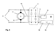
- Fig. 5 shows the DC motor system of Fig. 1 wherein the measuring circuit 30 is shown in more detail.
- the measuring circuit 30 comprises a signal generator 31, which provides a drive signal A with a specific frequency. Furthermore, a noise filter 2 is provided here in the embodiment of Fig. 1 that forms a resonant circuit with the complex resistance of one or more currently contacted windings of the DC motor 1.
- the drive signal A is in the Einkoppelpfad 3 of the noise filter 2 fed.
- the resulting measurement signal M is tapped behind the noise filter 2.
- the DC motor 1 acts here as a modulator which modulates the coupled drive signal A.
- the resulting modulated measurement signal M is tapped at the terminals of the DC motor 1 and fed to a detection unit 32 of the measurement circuit 30, which demodulates the resulting measurement signal M.
- the detection unit 32 determines, for example, the amplitude of the resulting from the coupling of the drive signal A measurement signal M.
- the assignment of the amplitude of the resulting measurement signal M for example, to an absolute rotation angle of the rotor of the DC motor 1 can in a determination unit 33 of the measuring circuit 30, with the detection unit 32nd connected.
Landscapes
- Engineering & Computer Science (AREA)
- Power Engineering (AREA)
- Physics & Mathematics (AREA)
- General Physics & Mathematics (AREA)
- Control Of Direct Current Motors (AREA)
- Control Of Motors That Do Not Use Commutators (AREA)
Description
- Die vorliegende Erfindung betrifft ein Gleichstrommotorsystem sowie ein Verfahren zum Ermitteln der Drehzahl und/oder des Drehwinkels eines Gleichstrommotors insbesondere eines erfindungsgemäßen Gleichstrommotorsystems.
- Zur Erfassung von Informationen über den Betriebszustand eines rotatorischen Elektromotors, insbesondere über die Drehzahl eines Gleichstrommotors, sind vielfältige Verfahren bekannt. Beispielsweise werden Sensoren, insbesondere Positionsgeber verwendet, die mit einem Detektor zusammenwirken, der diese Information aus der Stellung des Rotors und/oder aus der Änderung der Stellung des Rotors ermittelt. Oder die Wicklungen des Gleichstrommotors werden mit einem Strom angesteuert, und aus Schwankungen der Stromstärke wird auf die Drehzahl geschlossen. Auch aus dem Verlauf der Stromaufnahme beim Überstreichen der Kommutatorlamellen kann auf einen Wechsel zwischen den Kommutatorlamellen geschlossen werden, um die Drehzahl des Elektromotors zu ermitteln. Diese herkömmlichen Verfahren benötigen zusätzliche Sensoren oder aufwändige Filter, die teilweise schwer abzustimmen sind. Außerdem ist mit diesen Verfahren eine Bestimmung des Drehwinkels des Rotors nur schwer, ungenau oder gar nicht möglich.
- Bei Gleichstrommotoren entstehen Gasentladungen zwischen den Kommutatorlamellen und den die Kommutatorlamellen überstreichenden Bürsten, insbesondere beim Übergang einer Bürste von einer auf die nächste Kommutatorlamelle, die sich in Stromspitzen äußern und hochfrequente Störemissionen verursachen. Und auch bei schnellen Stromänderungen, beispielsweise bei Ein- und Ausschaltvorgängen elektrischer Verbraucher, entstehen im Bereich eines sehr breiten Frequenzbandes elektromagnetische Oberwellen.
- Um Störemissionen zu verringern, wird neben der Abschirmung der Störquellen die Entstehung solcher Störungen durch eine Begrenzung des Stromanstiegs reduziert, oder es werden Entstörfilter vorgesehen, die die Signale auf den Zuleitungen von und zur Störquelle filtern.
- Zur Reduzierung der von Gleichstrommotoren mit Kommutator verursachten Störemissionen sowie zur Oberwellenglättung beim Ein- und Ausschalten eines Gleichstrommotors werden üblicherweise Entstörfilter aus Widerständen, Kondensatoren und/oder Drosseln vorgesehen.
- Eine solche Entstörvorrichtung zeigt beispielsweise die Druckschrift
DE 10 2005 011 293 A1 , die neben der Kommutator- Entstörung gleichzeitig eine Abschaltspannugsimpuls- Begrenzung ermöglicht. Die Entstörvorrichtung weist zur Kommutator- Entstörung im elektrischen Pfad zumindest einer Anschlussleitung einen Durchlasskondensator und zusätzlich oder alternativ zwischen den Anschlussleitungen einen Cx- Kondensator zur Unterdrückung hochfrequenter Störemissionen auf. Der Durchlasskondensator wird mit Massepotential kontaktiert, so dass das Potential der durch diesen Kondensator kurzgeschlossenen Oberwellen auf das Massepotential gezogen wird und die Oberwellen stark gedämpft werden. Als Abschaltspannungsimpulsbegrenzung ist dem Gleichstrommotor ein elektrisches Bauteil, insbesondere ein Varistor parallel geschaltet. - Störemissionen in der Spannung oder im Strom eines Gleichstrommotors mit Kommutator können zur Bestimmung der Drehzahl ausgewertet werden, wie in
DE 19602362 beschrieben. - Aufgabe der vorliegenden Erfindung ist es, ein Gleichstrommotorsystem zu schaffen, das es ermöglicht, den Drehwinkel und/oder die Drehzahl eines Gleichstrommotors sehr genau und ohne Verwendung zusätzlicher Sensoren zu bestimmen und gleichzeitig den erforderlichen Schaltungs- und Bauteilaufwand zu minimieren.
- Die Aufgabe der Erfindung wird durch ein Gleichstrommotorsystem gemäß Patentanspruch 1 sowie ein Verfahren zum Ermitteln der Drehzahl und/oder des Drehwinkels eines Gleichstrommotors gemäß Patentanspruch 7 gelöst.
- Weitere vorteilhafte Ausgestaltungen der Erfindung sind in den Unteransprüchen angegeben.
- Gemäß einem ersten Aspekt umfasst das Gleichstrommotorsystem
- einen Gleichstrommotor mit einem Kommutator zum Ansteuern von Wicklungen eines Rotors des Gleichstrommotors,
- ein Entstörfilter zur Reduzierung von Störemissionen von und zum Gleichstrommotor, und
- eine Messschaltung zum Erfassen des Drehwinkels und/oder der Drehzahl des Gleichstrommotors, die mit Anschlüssen des Gleichstrommotors verbunden ist, wobei der Gleichstrommotor mit einem hochfrequenten Ansteuersignal beaufschlagbar, und am Gleichstrommotor ein resultierendes Messsignal abgreifbar und mittels der Messschaltung auswertbar ist,
- Das erfindungsgemäße Gleichstrommotorsystem umfasst demnach einen Gleichstrommotor mit einem Kommutator zum Ansteuern von Wicklungen eines Rotors des Gleichstrommotors, wobei der Kommutator ausgebildet ist, um abhängig von einem Drehwinkel des Rotors entweder eine erste Anzahl von Wicklungen oder eine davon unterschiedliche zweite Anzahl von Wicklungen gleichzeitig so zu kontaktieren, dass diese parallel zueinander verschaltet sind.
- Das Gleichstrommotorsystem umfasst weiterhin eine Messschaltung, die mit Anschlüssen des Gleichstrommotors verbunden ist.
- Die Messschaltung umfasst dabei bevorzugt einen Signalgenerator zum Bereitstellen des Ansteuersignals, das an den Gleichstrommotor anlegbar ist, so dass an dem Gleichstrommotor ein resultierendes Messsignal abgreifbar ist, eine Erfassungseinheit zum Auswerten des resultierenden Messsignals, und eine Bestimmungseinheit, um anhand des ausgewerteten Signals die Drehzahl und/oder den Drehwinkel des Rotors des Gleichstrommotors zu bestimmen. Sie ermöglicht es, durch Bereitstellen des Ansteuersignals an den Gleichstrommotor und durch Auswerten des resultierenden Messsignals Änderungen des komplexen Widerstands des Gleichstrommotors als Antwort auf das Ansteuersignal zu ermitteln.
- Dabei ändert sich nicht nur der komplexe Widerstand des Gleichstrommotors aufgrund der Änderung des komplexen Widerstandes der einzelnen Wicklungen des Gleichstrommotors, sondern insbesondere das Überstreichen mehrerer Kommutatorlamellen äußert sich in einer Änderung des komplexen Widerstandes.
- Es ist vorgesehen, insbesondere Änderungen eines Frequenzverhaltens des Gleichstrommotors während der Rotation aufgrund der drehzahl- und/oder drehwinkelabhängigen Änderungen seines komplexen Widerstandes bzw. Änderungen des Frequenzverhaltens einer Schaltung, die mit dem komplexen Widerstand des Gleichstrommotors zusammenwirkt, zum Bestimmen der Drehzahl und/oder des Drehwinkels zu verwenden.
- Dabei wirkt der sich drehende Gleichstrommotor als Modulator, so dass man aus dem demodulierten resultierenden Messsignal insbesondere die Drehzahl und/oder den Drehwinkel ableiten kann.
- Als Schaltung, mit der der komplexe Widerstand des Gleichstrommotors zusammenwirkt, wird hier erfindungsgemäß das Entstörfilter des Gleichstrommotors genutzt.
- Das erfindungsgemäße Gleichstrommotorsystem nutzt das Entstörfilter für den Gleichstrommotor daher nicht nur zur Entstörung der Störemissionen von und zum Gleichstrommotor, sondern es nutzt gleichzeitig die Möglichkeit, das Ansteuersignal zum Erfassen des Drehwinkels und/oder der Drehzahl des Gleichstrommotors in das Entstörfilter einzukoppeln.
- Da die für die Entstörung benötigten Bauteile zur Entstörung des Gleichstrommotors ohnehin benötigt werden, ist der Schaltungsaufwand für das erfindungsgemäße Gleichstrommotorsystem sehr gering.
- In einer bevorzugten Ausführungsform umfasst das Entstörfilter zwei Cy-Kondensatoren sowie einen Cx - Kondensator, wobei die Cy- Kondensatoren mittels einer gemeinsamen elektrischen Verbindung auf ein schwebendes Massepotential geführt sind. Dabei sind der Cx - Kondensator sowie die Cy - Kondensatoren vorgesehen, um hochfrequente symmetrische (Gegentakt-) sowie asymmetrische (Gleichtakt-) Störströme kurz zu schließen.
- In einer weiteren bevorzugten Ausführungsform umfasst das Entstörfilter zumindest eine Längsdrossel. Da der induktive Blindwiderstand mit steigender Frequenz zunimmt, stellt die Längsdrossel für hochfrequente Signale einen hohen Widerstand dar, so dass durch die Längsdrossel Störsignale gedämpft werden.
- Um das Ansteuersignal in das Gleichstrommotorsystem einzukoppeln, eignen sich insbesondere Kondensatoren oder Drosseln. Der Fachmann versteht, dass das Entstörfilter und insbesondere das Bauteil, in das das Ansteuersignal eingekoppelt wird, für die Frequenz des Ansteuersignals durchlässig sein müssen. Als Frequenz des Ansteuersignals wird bevorzugt eine Frequenz gewählt, die zumindest im MHz-Bereich liegt.
- Vorzugsweise ist das Ansteuersignal in die gemeinsame elektrische Verbindung und somit zwischen die Cy- Kondensatoren einkoppelbar. Das schwebende Massepotential, auf das die gemeinsame elektrische Verbindung geführt ist, wird dabei bevorzugt durch ein Gehäuse des Gleichstrommotors gebildet.
- Weiterhin bevorzugt ist das Ansteuersignal in einen elektrischen Pfad der Anschlussleitung einkoppelbar und damit der Versorgungsspannung des Gleichstrommotors überlagert.
- Ebenfalls bevorzugt umfasst der Cx- Kondensator eine Reihenschaltung aus zwei Kondensatoren und das Ansteuersignal ist zwischen diese beiden Kondensatoren einkoppelbar. Weiterhin bevorzugt ist die Längsdrossel ein Teil eines Übertragers und das Ansteuersignal ist über den Übertrager in das Entstörfilter einkoppelbar. Sofern das Ansteuersignal zwischen eine Reihenschaltung aus zwei den Cx-Kondensator bildenden Kondensatoren oder in eine als Übertrager ausgeführte Längsdrossel eingekoppelt wird, sind Entstörfilter einsetzbar, die auf Cy-Kondensatoren verzichten oder bei denen die Cy- Kondensatoren anstelle auf eine schwebende Masse auf Massepotential (GND) geführt sind.
- Der Gleichstrommotor wird daher mit dem Ansteuersignal beaufschlagt, um aus der Änderung des Frequenzverhaltens bzw. des komplexen Widerstandes des Gleichstrommotors als Antwort auf das Ansteuersignal auf die Drehzahl und/oder den Drehwinkel des Gleichstrommotors zu schließen. Dabei werden keine zusätzlichen Sensoren benötigt und die Drehzahl sowie der Drehwinkel des Gleichstrommotors sind sehr genau erfassbar. Außerdem nutzt das Gleichstrommotorsystem ohnehin für die Entstörung benötigte Bauteile, so dass der Bauteileaufwand sehr gering ist.
- Eine bevorzugte Ausführungsform, die die Aufgabe ebenfalls löst, ist ein Verfahren zum Ermitteln der Drehzahl und/oder des Drehwinkels eines Gleichstrommotors, insbesondere eines erfindungsgemäßen Gleichstrommotorsystems, mit folgenden Schritten
- Einkoppeln eines hochfrequenten Ansteuersignals in einen Einkoppelpfad eines Entstörfilters eines Gleichstrommotors,
- Abgreifen eines resultierenden Messsignals am Gleichstrommotor,
- Auswerten des resultierenden Messsignals und Bestimmen des Drehwinkels und/oder der Drehzahl des Gleichstrommotors.
- Bei dem erfindungsgemäßen Verfahren kann das Ansteuersignal über das Entstörfilter, das mit einem komplexen Widerstand des Gleichstrommotors ein Filter für das Ansteuersignal und/oder einen Schwingkreis bildet, an den Gleichstrommotor angelegt werden, so dass ein komplexer Widerstand des Gleichstrommotors das Frequenzverhalten des Filters und/oder des Schwingkreises beeinflusst. Eine Änderung des komplexen Widerstandes des Gleichstrommotors schlägt sich daher in einer Änderung des Frequenzverhaltens des Filters oder des Schwingkreises nieder.
- Durch Auswertung des resultierenden Messsignals, dessen Frequenzverhalten durch die Rotation des Gleichstrommotors sowie durch die jeweils kontaktierte Wicklung beziehungsweise kontaktierten Wicklungen des Gleichstrommotors beeinflusst ist, ist daher ein Rückschluss auf den Drehwinkel und/oder die Drehzahl des Gleichstrommotors möglich.
- Bevorzugt ist das hochfrequente Ansteuersignal periodisch.
- In dieser Ausführungsform kann aus dem Verlauf einer Amplitude des resultierenden Messsignals, eines Amplitudenverhältnisses zwischen den Amplituden des Ansteuersignals und des resultierenden Messsignals, einer Phasenverschiebung zwischen dem Ansteuersignal und dem resultierenden Messsignal, und/oder einem Verlauf einer Frequenzverschiebung zwischen dem resultierenden Messsignal und dem Ansteuersignal in der Messschaltung die Hauptfrequenz des ermittelten Verlaufs bestimmt und die Drehzahl ermittelt werden.
- Außerdem kann beispielsweise durch Identifizieren einer bestimmten Wicklung die absolute Position des Rotors bestimmt werden. Oder der Drehwinkel kann durch Vergleichen eines Abschnittes des Verlaufs des resultierenden Messsignals mit einem vorbestimmten Signalprofil ermittelt werden.
- Das obige Verfahren ermöglicht es in einfacher Weise ohne Vorsehen eines zusätzlichen Sensors den Drehwinkel und/oder die Drehzahl des Rotors zu bestimmen, wobei der Schaltungsaufwand durch die Nutzung des Entstörfilters sehr gering ist.
- Im Folgenden wird die Erfindung durch Figuren beschrieben. Die Figuren sind lediglich beispielhaft und schränken den allgemeinen Erfindungsgedanken nicht ein.
- Fig. 1 - Fig. 4
- zeigen verschiedene Ausführungsformen eines erfindungsgemäßen Gleichstrommotorsystems,
- Fig. 5
- zeigt das Gleichstrommotorsystem der
Fig. 1 , wobei die Messschaltung detaillierter dargestellt ist. -
Fig. 1 zeigt eine erste Ausführungsform eines erfindungsgemäßen Gleichstrommotorsystems. Das Gleichstrommotorsystem umfasst einen Gleichstrommotor 1 mit Kommutatoren 12, ein Entstörfilter 2, welches Störemissionen von und zum Gleichstrommotor 1 entstört, sowie eine Messschaltung 30. - Der Gleichstrommotor 1 wird mittels einer Gleichspannungsquelle, die zwischen Zuleitungen 4 angeordnet aber hier nicht dargestellt ist, gespeist. Das Entstörfilter 2 umfasst einen Einkoppelpfad 3 zum Einkoppeln eines hochfrequenten Ansteuersignals A, welches mittels eines Signalgenerators 31 der Messschaltung (siehe auch
Fig. 5 ) erzeugt wird. Das Ansteuersignal A wird zur Ermittlung von Eigenschaften des Gleichstrommotors 1 verwendet, insbesondere zur Ermittlung der Drehzahl und/oder des Drehwinkels des Gleichstrommotors 1, indem ein resultierendes Messsignal M in einer Erfassungseinheit 32 der Messschaltung 30 (siehe auchFig. 5 ) erfasst und in einer Bestimmungseinheit 33 der Messschaltung 30 (siehe auchFig. 5 ) ausgewertet wird. - Dabei wird die Änderung des komplexen Widerstandes des Gleichstrommotors 1 während seiner Rotation ausgenutzt, indem der komplexe Widerstand des Gleichstrommotors 1 mit dem Entstörfilter 2 beziehungsweise Komponenten des Entstörfilters 2 einen Schwingkreis bildet, dessen Frequenzverhalten sich während der Rotation des Gleichstrommotors 1 ändert. Aufgrund dessen ändert sich das resultierende Messsignal M, so dass anhand einer Auswertung des resultierenden Messsignals M Rückschlüsse auf den Gleichstrommotor 1 möglich sind.
- In der in
Fig. 1 dargestellten ersten Ausführungsform des Entstörfilters 2 ist der Einkoppelpfad 3 zwischen zwei in Reihe geschaltete Cy- Kondensatoren 5, 6 des Entstörfilters 2 geführt, die dem Gleichstrommotor 1 parallel geschaltet sind. Außerdem umfasst das Entstörfilter 2 einen weiteren dem Gleichstrommotor 1 sowie den beiden in Reihe geschalteten Cy- Kondensatoren 5, 6 parallel geschalteten Cx-Kondensator 7. - Die Cy- Kondensatoren 5, 6 sind mittels einer gemeinsamen elektrischen Verbindung 13 auf ein schwebendes Massepotential 11 geführt, welches hier das Gehäuse 11 des Gleichstrommotors 1 ist.
-
Fig. 2 zeigt eine zweite Ausführungsform eines erfindungsgemäßen Gleichstrommotorsystems. Die Gleichstrommotorsysteme derFig. 1 und derFig. 2 unterscheiden sich, indem der Cx- Kondensator 7 des Entstörfilters 2 hier zwei in Reihe geschaltete Kondensatoren umfasst, wobei der Einkoppelpfad 3 für das Ansteuersignal A in die Verbindung zwischen diese beiden in Reihe geschalteten Kondensatoren des Cx- Kondensators 7 geführt ist. - Die beiden Gleichstrommotorsysteme der
Fig. 1 und Fig. 2 sehen daher eine kapazitive Einkopplung des Ansteuersignals A vor. - Durch gestrichelte Pfeile zeigen die
Fig. 1 und dieFig. 2 außerdem die beiden alternativen Ausführungen, bei denen das Ansteuersignal A in einen elektrischen Pfad der beiden Anschlussleitungen 4 eingekoppelt und somit der Versorgungsspannung des Gleichstrommotors 1 überlagert wird. - Bei dem Gleichstrommotorsystem der
Fig. 3 umfasst das Entstörfilter 2 zusätzlich Längsdrosseln 8, 9, wobei zumindest eine der Längsdrosseln 8, 9 als Teil eines Übertragers 9 ausgeführt ist, um das Ansteuersignal A induktiv in den Einkoppelpfad 3 einzukoppeln. - Das Entstörfilter 2 des Gleichstrommotorsystems der
Fig. 4 sieht ebenfalls eine induktive Einkopplung des Ansteuersignals A vor, wobei hier ebenfalls eine der Längsdrosseln 8, 9, 10 in den speisenden Zuleitungen 4 des Gleichstrommotors 1 als Teil eines Übertragers 9 mit Einkoppelpfad 3 vorgesehen ist. - In den
Fig. 2 -Fig. 4 ist die Messschaltung der Übersicht halber nicht dargestellt. Gleichwohl gelten die inFig. 5 gemachten Ausführungen auch für diese Ausführungsformen des Gleichstrommotorsystems. -
Fig. 5 zeigt das Gleichstrommotorsystem derFig. 1 , wobei die Messschaltung 30 detaillierter dargestellt ist. - Die Messschaltung 30 umfasst einen Signalgenerator 31, der ein Ansteuersignal A mit einer bestimmten Frequenz bereitstellt. Weiterhin ist ein Entstörfilter 2 vorgesehen, hier in der Ausführungsform der
Fig. 1 , das mit dem komplexen Widerstand einer oder mehrerer aktuell kontaktierten Wicklungen des Gleichstrommotors 1 einen Schwingkreis bildet. Das Ansteuersignal A wird in den Einkoppelpfad 3 des Entstörfilters 2 eingespeist. Das resultierende Messsignal M wird hinter dem Entstörfilter 2 abgegriffen. - Der Gleichstrommotor 1 wirkt hier wie ein Modulator, der das eingekoppelte Ansteuersignal A moduliert. Das resultierende modulierte Messsignal M wird an den Anschlüssen des Gleichstrommotor 1 abgegriffen und einer Erfassungseinheit 32 der Messschaltung 30 zugeführt, die das resultierende Messsignal M demoduliert. Die Erfassungseinheit 32 ermittelt beispielsweise die Amplitude des aus der Einkopplung des Ansteuersignals A resultierenden Messsignals M. Die Zuordnung der Amplitude des resultierenden Messsignals M beispielsweise zu einem absoluten Drehwinkel des Rotors des Gleichstrommotors 1 kann in einer Bestimmungseinheit 33 der Messschaltung 30, die mit der Erfassungseinheit 32 verbunden ist, durchgeführt werden.
- Durch Auswertung von Verschiebungen der Amplitude, Phase und/oder der Frequenz des resultierenden Messsignals M im Vergleich zum Ansteuersignal A kann somit auf die Drehzahl und/oder den Drehwinkel des Gleichstrommotors 1 geschlossen werden.
- Aufgrund der Nutzung des Entstörfilters 2 zum Einkoppeln des definierten Ansteuersignals A ist der Schaltungsaufwand dabei sehr gering.
Claims (10)
- Gleichstrommotorsystem, umfassend- einen Gleichstrommotor (1) mit einem Kommutator (12) zum Ansteuern von wicklungen des Gleichstrommotors (1),wobei das Entstörfilter (2) einen Einkoppelpfad (3) für das hochfrequente Ansteuersignal (A) aufweist
ein Entstörfilter (2) zur Reduzierung von Störemissionen von und zum Gleichstrommotor (1), und
eine Messschaltung (30), wobei der Gleichstrommotor (1) mit einem hochfrequenten Ansteuersignal (A) beaufschlagbar, und am Gleichstrommotor (1) ein resultierendes Messsignal (M) abgreifbar und mittels der Messschaltung (30) auswertbar ist,
dadurch gekennzeichnet, dass
die Messschaltung (30) einen Signalgenerator (31) zum Erzeugen des Ansteuersignals (3) umfasst und zum Erfassen des Drehwinkels und/oder der Drehzahl des Gleichstrommotors (1) vorgesehen ist, und dass das Entstörfilter (2) für die Frequenz des Ansteuersignals (A) durchlässig ausgebildet ist. - Gleichstrommotorsystem nach Anspruch 1, dadurch gekennzeichnet, dass der Gleichstrommotor (1) mittels einer Gleichspannungsquelle gespeist ist.
- Gleichstrommotorsystem nach einem der vorherigen Ansprüche, dadurch gekennzeichnet, dass- das Ansteuersignal (A) der Versorgungsspannung überlagert ist, oder- der Einkoppelpfad (3) für das Ansteuersignal (A) zwischen zwei einen Cx- Kondensator (7) bildende, in Reihe geschaltete Kondensatoren vorgesehen ist, oder- der Einkoppelpfad (3) für das Ansteuersignal (A) zwischen zwei mittels einer gemeinsamen elektrischen Verbindung (13) auf ein schwebendes Massepotential (11) geführte Cy- Kondensatoren (5, 6) vorgesehen ist, oder- der Einkoppelpfad (3) für das Ansteuersignal (A) in eine als Teil eines Übertragers ausgebildete Längsdrossel (9) vorgesehen ist.
- Gleichstrommotorsystem nach einem der vorherigen Ansprüche, dadurch gekennzeichnet, dass das Entstörfilter (2) zwei Cy- Kondensatoren (5, 6) sowie einen Cx Kondensator (7) umfasst, wobei die Cy- Kondensatoren (5, 6) mittels einer gemeinsamen elektrischen Verbindung (13) auf ein schwebendes Massepotential (11) geführt sind.
- Gleichstrommotorsystem nach einem der vorherigen Ansprüche, dadurch gekennzeichnet, dass das Entstörfilter (2) zumindest eine Längsdrossel (8, 9, 10) umfasst:
- Verfahren zum Ermitteln der Drehzahl und/oder des Drehwinkels eines Gleichstrommotors (1) mit folgenden Schritten- Beaufschlagen eines Gleichstrommotorsystems, welches einen Gleichstrommotor (1), ein Entstörfilter (2) sowie eine Messschaltung (30) umfasst, mit einem Ansteuersignal (A);
Abgreifen eines resultierenden Messsignals (M) am Gleichstrommotor (1);- Auswerten des resultierenden Messsignals (M);dadurch gekennzeichnet, dass
das Ansteuersignal (A) ein hochfrequentes Ansteuersignal (A) ist, wobei aus dem resultierenden Messsignal (M) der Drehwinkelund/oder die Drehzahl des Gleichstrommotors (1) bestimmt wird, wobei das Entstörfilter (2) für die Frequenz des Ansteuersignals (A) durchlässig ist, und wobei das Ansteuersignal (A) in einen Einkoppelpfad (3) des Entstörfilters (2) des Gleichstrommotors (1) eingekoppelt wird. - Verfahren nach Anspruch 6, dadurch gekennzeichnet, dass durch Auswertung von Verschiebungen der Amplitude, Phase und/oder der Frequenz des resultierenden Messsignals (M) im Vergleich zum Ansteuersignal (A) auf die Drehzahl und/oder den Drehwinkel des Gleichstrommotors (1) geschlossen wird.
- Verfahren nach einem der Ansprüche 6 - 7, dadurch gekennzeichnet, dass der Gleichstrommotor (1) mittels einer Gleichspannungsquelle gespeist wird.
- Verfahren nach einem der Ansprüche 6 - 8, dadurch gekennzeichnet, dass- das Ansteuersignal der Versorgungsspannung des Gleichstrommotors überlagert ist, oder- das Ansteuersignal (A) zwischen zwei einen Cx- Kondensator (7) bildende, in Reihe geschaltete Kondensatoren eingekoppelt wird, oder- das Ansteuersignal (A) zwischen zwei mittels einer gemeinsamen elektrischen Verbindung (13) auf ein schwebendes Massepotential (11) geführte Cy- Kondensatoren (5, 6) eingekoppelt wird, oder- das Ansteuersignal (A) in eine als Teil eines Übertragers ausgebildete Längsdrossel (9) eingekoppelt wird.
- Verfahren nach einem der Ansprüche 6 - 9, dadurch gekennzeichnet, dass das hochfrequente Ansteuersignal (A) periodisch ist.
Applications Claiming Priority (2)
| Application Number | Priority Date | Filing Date | Title |
|---|---|---|---|
| DE102009026520A DE102009026520A1 (de) | 2009-05-28 | 2009-05-28 | Entstörfilter für einen Gleichstrommotor |
| PCT/EP2010/054269 WO2010136240A1 (de) | 2009-05-28 | 2010-03-31 | Entstörfilter für einen gleichstrommotor |
Publications (2)
| Publication Number | Publication Date |
|---|---|
| EP2436111A1 EP2436111A1 (de) | 2012-04-04 |
| EP2436111B1 true EP2436111B1 (de) | 2013-02-13 |
Family
ID=42333267
Family Applications (1)
| Application Number | Title | Priority Date | Filing Date |
|---|---|---|---|
| EP10712413A Not-in-force EP2436111B1 (de) | 2009-05-28 | 2010-03-31 | Entstörfilter für einen gleichstrommotor |
Country Status (3)
| Country | Link |
|---|---|
| EP (1) | EP2436111B1 (de) |
| DE (1) | DE102009026520A1 (de) |
| WO (1) | WO2010136240A1 (de) |
Families Citing this family (2)
| Publication number | Priority date | Publication date | Assignee | Title |
|---|---|---|---|---|
| DE102017217626A1 (de) * | 2017-10-04 | 2019-04-04 | Brose Fahrzeugteile Gmbh & Co. Kommanditgesellschaft, Bamberg | Verfahren und Vorrichtung zur Erfassung einer Rotationsgröße |
| KR20200062286A (ko) | 2017-10-04 | 2020-06-03 | 브로제 파초이크타일레 에스이 운트 코. 콤만디트게젤샤프트, 밤베르크 | 회전 변수를 결정하기 위한 방법 및 장치 |
Family Cites Families (6)
| Publication number | Priority date | Publication date | Assignee | Title |
|---|---|---|---|---|
| US4204156A (en) * | 1978-07-03 | 1980-05-20 | General Electric Company | Apparatus for aligning brushes of a dynamoelectric machine |
| DE19602362A1 (de) * | 1996-01-24 | 1997-07-31 | Teves Gmbh Alfred | Schaltungsanordnung zur Bestimmung der Drehzahl eines Kommutatormotors |
| DE10202161A1 (de) * | 2002-01-22 | 2003-08-07 | Bosch Gmbh Robert | Vorrichtung zur Funkentstörung einer elektrischen Kommutatormaschine |
| DE102005011293A1 (de) | 2005-03-11 | 2006-09-14 | Robert Bosch Gmbh | Entstörvorrichtung zur Unterdrückung hochfrequenter Störemissionen eines Gleichstrommotors |
| US20070031131A1 (en) * | 2005-08-04 | 2007-02-08 | Mountain Engineering Ii, Inc. | System for measuring the position of an electric motor |
| DE102007051251A1 (de) * | 2007-10-26 | 2009-04-30 | Robert Bosch Gmbh | Entstörvorrichtung für das Kommutierungssystem eines Gleichstrommotors |
-
2009
- 2009-05-28 DE DE102009026520A patent/DE102009026520A1/de not_active Withdrawn
-
2010
- 2010-03-31 WO PCT/EP2010/054269 patent/WO2010136240A1/de not_active Ceased
- 2010-03-31 EP EP10712413A patent/EP2436111B1/de not_active Not-in-force
Also Published As
| Publication number | Publication date |
|---|---|
| WO2010136240A1 (de) | 2010-12-02 |
| DE102009026520A1 (de) | 2010-12-02 |
| EP2436111A1 (de) | 2012-04-04 |
Similar Documents
| Publication | Publication Date | Title |
|---|---|---|
| DE69024975T2 (de) | Spektrumerfassung von lichtbögen und radiofrequenzen | |
| EP2130293B1 (de) | Verfahren und vorrichtung zur dreherfassung eines bürstenbetriebenen gleichstrommotors | |
| EP3053176B1 (de) | Verfahren und vorrichtung zum überwachen zumindest eines elektronischen schaltkontakts für ein fahrzeug | |
| DE60301329T2 (de) | Elektromotor-überwachungssystem | |
| EP1537428B1 (de) | Verfahren und vorrichtung zur erfassung von bürstenfeuer und funkenerosion an elektrischen maschinen | |
| EP3715883A1 (de) | Erfassen einer teilentladung | |
| DE69423238T2 (de) | Anordnung zur bestätigung des anhaltens eines motor | |
| EP3075075A1 (de) | Entstörfilter für einen gleichstrommotor und gleichstrommotor damit | |
| EP2776867A2 (de) | Objektfinder | |
| WO2010136240A1 (de) | Entstörfilter für einen gleichstrommotor | |
| DE102010012781A1 (de) | Drehmelder | |
| DE102020205027A1 (de) | Steuergerät zum Ansteuern einer elektrischen Maschine, Sensoranordnung zur Bestimmung einer Rotorposition einer elektrischen Maschine | |
| WO2019068517A1 (de) | VERFAHREN UND VORRICHTUNG ZUR ERFASSUNG EINER ROTATIONSGRÖßE | |
| DE102014211235A1 (de) | Vorrichtung zum Betreiben eines Resolvers, Resolvereinrichtung und Verfahren zum Betreiben einer Resolvereinrichtung | |
| WO2019179645A1 (de) | Verfahren sowie messanordnung zur erfassung eines elektromagnetischen störeinflusses auf einen leitungskern einer elektrischen leitung | |
| EP3521131A1 (de) | Sensor, system und verfahren zum erfassen von metallteilen | |
| EP3707479B1 (de) | Positionierung von motoren mittels kapazitiver messung | |
| EP4034898B1 (de) | Vorrichtung zur erfassung eines hochfrequenten ereignissignals in einer elektrischen rotierenden maschine | |
| DE102019107725A1 (de) | Vorrichtung und ein Verfahren zur Detektion eines Windungsschlusses einer Statorspule | |
| EP4187208B1 (de) | Anordnung und verfahren zur positionserfassung mit fehlererkennung mit einem lagegeber | |
| EP2266200B1 (de) | Elektromotor, motorsystem und verfahren zur bestimmung einer absoluten winkellage eines rotors eines elektromotors | |
| DE102009002654A1 (de) | Verfahren und Vorrichtung zum Bestimmen einer absoluten Winkellage eines Rotors eines kommutierten Elektromotors | |
| WO1999001774A1 (de) | Diagnoseeinrichtung zur erkennung von fehlschlüssen bei einem induktiven sensor | |
| EP2435836A1 (de) | Bestimmung von motoreigenschaften mittels einer messkomponente | |
| EP2249472A2 (de) | Verfahren und Vorrichtung zum Bestimmen einer absoluten Winkellage eines Rotors eines Elektromotors |
Legal Events
| Date | Code | Title | Description |
|---|---|---|---|
| PUAI | Public reference made under article 153(3) epc to a published international application that has entered the european phase |
Free format text: ORIGINAL CODE: 0009012 |
|
| 17P | Request for examination filed |
Effective date: 20111228 |
|
| AK | Designated contracting states |
Kind code of ref document: A1 Designated state(s): AT BE BG CH CY CZ DE DK EE ES FI FR GB GR HR HU IE IS IT LI LT LU LV MC MK MT NL NO PL PT RO SE SI SK SM TR |
|
| DAX | Request for extension of the european patent (deleted) | ||
| GRAP | Despatch of communication of intention to grant a patent |
Free format text: ORIGINAL CODE: EPIDOSNIGR1 |
|
| RIC1 | Information provided on ipc code assigned before grant |
Ipc: H02P 7/285 20060101AFI20120928BHEP Ipc: H02K 11/02 20060101ALI20120928BHEP Ipc: H02P 29/00 20060101ALI20120928BHEP Ipc: H01R 39/54 20060101ALI20120928BHEP Ipc: G01D 5/12 20060101ALI20120928BHEP Ipc: G01P 3/48 20060101ALI20120928BHEP |
|
| GRAS | Grant fee paid |
Free format text: ORIGINAL CODE: EPIDOSNIGR3 |
|
| GRAA | (expected) grant |
Free format text: ORIGINAL CODE: 0009210 |
|
| AK | Designated contracting states |
Kind code of ref document: B1 Designated state(s): AT BE BG CH CY CZ DE DK EE ES FI FR GB GR HR HU IE IS IT LI LT LU LV MC MK MT NL NO PL PT RO SE SI SK SM TR |
|
| REG | Reference to a national code |
Ref country code: GB Ref legal event code: FG4D Free format text: NOT ENGLISH |
|
| REG | Reference to a national code |
Ref country code: AT Ref legal event code: REF Ref document number: 596934 Country of ref document: AT Kind code of ref document: T Effective date: 20130215 |
|
| REG | Reference to a national code |
Ref country code: IE Ref legal event code: FG4D Free format text: LANGUAGE OF EP DOCUMENT: GERMAN |
|
| REG | Reference to a national code |
Ref country code: DE Ref legal event code: R096 Ref document number: 502010002317 Country of ref document: DE Effective date: 20130411 |
|
| REG | Reference to a national code |
Ref country code: NL Ref legal event code: VDEP Effective date: 20130213 |
|
| REG | Reference to a national code |
Ref country code: LT Ref legal event code: MG4D |
|
| PG25 | Lapsed in a contracting state [announced via postgrant information from national office to epo] |
Ref country code: BG Free format text: LAPSE BECAUSE OF FAILURE TO SUBMIT A TRANSLATION OF THE DESCRIPTION OR TO PAY THE FEE WITHIN THE PRESCRIBED TIME-LIMIT Effective date: 20130513 Ref country code: NO Free format text: LAPSE BECAUSE OF FAILURE TO SUBMIT A TRANSLATION OF THE DESCRIPTION OR TO PAY THE FEE WITHIN THE PRESCRIBED TIME-LIMIT Effective date: 20130513 Ref country code: ES Free format text: LAPSE BECAUSE OF FAILURE TO SUBMIT A TRANSLATION OF THE DESCRIPTION OR TO PAY THE FEE WITHIN THE PRESCRIBED TIME-LIMIT Effective date: 20130524 Ref country code: SE Free format text: LAPSE BECAUSE OF FAILURE TO SUBMIT A TRANSLATION OF THE DESCRIPTION OR TO PAY THE FEE WITHIN THE PRESCRIBED TIME-LIMIT Effective date: 20130213 Ref country code: LT Free format text: LAPSE BECAUSE OF FAILURE TO SUBMIT A TRANSLATION OF THE DESCRIPTION OR TO PAY THE FEE WITHIN THE PRESCRIBED TIME-LIMIT Effective date: 20130213 Ref country code: IS Free format text: LAPSE BECAUSE OF FAILURE TO SUBMIT A TRANSLATION OF THE DESCRIPTION OR TO PAY THE FEE WITHIN THE PRESCRIBED TIME-LIMIT Effective date: 20130613 |
|
| PG25 | Lapsed in a contracting state [announced via postgrant information from national office to epo] |
Ref country code: LV Free format text: LAPSE BECAUSE OF FAILURE TO SUBMIT A TRANSLATION OF THE DESCRIPTION OR TO PAY THE FEE WITHIN THE PRESCRIBED TIME-LIMIT Effective date: 20130213 Ref country code: PT Free format text: LAPSE BECAUSE OF FAILURE TO SUBMIT A TRANSLATION OF THE DESCRIPTION OR TO PAY THE FEE WITHIN THE PRESCRIBED TIME-LIMIT Effective date: 20130613 Ref country code: GR Free format text: LAPSE BECAUSE OF FAILURE TO SUBMIT A TRANSLATION OF THE DESCRIPTION OR TO PAY THE FEE WITHIN THE PRESCRIBED TIME-LIMIT Effective date: 20130514 Ref country code: FI Free format text: LAPSE BECAUSE OF FAILURE TO SUBMIT A TRANSLATION OF THE DESCRIPTION OR TO PAY THE FEE WITHIN THE PRESCRIBED TIME-LIMIT Effective date: 20130213 Ref country code: PL Free format text: LAPSE BECAUSE OF FAILURE TO SUBMIT A TRANSLATION OF THE DESCRIPTION OR TO PAY THE FEE WITHIN THE PRESCRIBED TIME-LIMIT Effective date: 20130213 Ref country code: SI Free format text: LAPSE BECAUSE OF FAILURE TO SUBMIT A TRANSLATION OF THE DESCRIPTION OR TO PAY THE FEE WITHIN THE PRESCRIBED TIME-LIMIT Effective date: 20130213 |
|
| BERE | Be: lapsed |
Owner name: ROBERT BOSCH G.M.B.H. Effective date: 20130331 |
|
| PG25 | Lapsed in a contracting state [announced via postgrant information from national office to epo] |
Ref country code: HR Free format text: LAPSE BECAUSE OF FAILURE TO SUBMIT A TRANSLATION OF THE DESCRIPTION OR TO PAY THE FEE WITHIN THE PRESCRIBED TIME-LIMIT Effective date: 20130213 |
|
| PG25 | Lapsed in a contracting state [announced via postgrant information from national office to epo] |
Ref country code: SK Free format text: LAPSE BECAUSE OF FAILURE TO SUBMIT A TRANSLATION OF THE DESCRIPTION OR TO PAY THE FEE WITHIN THE PRESCRIBED TIME-LIMIT Effective date: 20130213 Ref country code: NL Free format text: LAPSE BECAUSE OF FAILURE TO SUBMIT A TRANSLATION OF THE DESCRIPTION OR TO PAY THE FEE WITHIN THE PRESCRIBED TIME-LIMIT Effective date: 20130213 Ref country code: RO Free format text: LAPSE BECAUSE OF FAILURE TO SUBMIT A TRANSLATION OF THE DESCRIPTION OR TO PAY THE FEE WITHIN THE PRESCRIBED TIME-LIMIT Effective date: 20130213 Ref country code: EE Free format text: LAPSE BECAUSE OF FAILURE TO SUBMIT A TRANSLATION OF THE DESCRIPTION OR TO PAY THE FEE WITHIN THE PRESCRIBED TIME-LIMIT Effective date: 20130213 Ref country code: MC Free format text: LAPSE BECAUSE OF NON-PAYMENT OF DUE FEES Effective date: 20130331 Ref country code: CZ Free format text: LAPSE BECAUSE OF FAILURE TO SUBMIT A TRANSLATION OF THE DESCRIPTION OR TO PAY THE FEE WITHIN THE PRESCRIBED TIME-LIMIT Effective date: 20130213 Ref country code: DK Free format text: LAPSE BECAUSE OF FAILURE TO SUBMIT A TRANSLATION OF THE DESCRIPTION OR TO PAY THE FEE WITHIN THE PRESCRIBED TIME-LIMIT Effective date: 20130213 |
|
| PLBE | No opposition filed within time limit |
Free format text: ORIGINAL CODE: 0009261 |
|
| STAA | Information on the status of an ep patent application or granted ep patent |
Free format text: STATUS: NO OPPOSITION FILED WITHIN TIME LIMIT |
|
| REG | Reference to a national code |
Ref country code: IE Ref legal event code: MM4A |
|
| 26N | No opposition filed |
Effective date: 20131114 |
|
| PG25 | Lapsed in a contracting state [announced via postgrant information from national office to epo] |
Ref country code: IE Free format text: LAPSE BECAUSE OF NON-PAYMENT OF DUE FEES Effective date: 20130331 Ref country code: BE Free format text: LAPSE BECAUSE OF NON-PAYMENT OF DUE FEES Effective date: 20130331 |
|
| REG | Reference to a national code |
Ref country code: DE Ref legal event code: R097 Ref document number: 502010002317 Country of ref document: DE Effective date: 20131114 |
|
| PG25 | Lapsed in a contracting state [announced via postgrant information from national office to epo] |
Ref country code: MT Free format text: LAPSE BECAUSE OF FAILURE TO SUBMIT A TRANSLATION OF THE DESCRIPTION OR TO PAY THE FEE WITHIN THE PRESCRIBED TIME-LIMIT Effective date: 20130213 |
|
| REG | Reference to a national code |
Ref country code: CH Ref legal event code: PL |
|
| GBPC | Gb: european patent ceased through non-payment of renewal fee |
Effective date: 20140331 |
|
| PG25 | Lapsed in a contracting state [announced via postgrant information from national office to epo] |
Ref country code: CH Free format text: LAPSE BECAUSE OF NON-PAYMENT OF DUE FEES Effective date: 20140331 Ref country code: LI Free format text: LAPSE BECAUSE OF NON-PAYMENT OF DUE FEES Effective date: 20140331 Ref country code: GB Free format text: LAPSE BECAUSE OF NON-PAYMENT OF DUE FEES Effective date: 20140331 |
|
| PG25 | Lapsed in a contracting state [announced via postgrant information from national office to epo] |
Ref country code: SM Free format text: LAPSE BECAUSE OF FAILURE TO SUBMIT A TRANSLATION OF THE DESCRIPTION OR TO PAY THE FEE WITHIN THE PRESCRIBED TIME-LIMIT Effective date: 20130213 |
|
| PG25 | Lapsed in a contracting state [announced via postgrant information from national office to epo] |
Ref country code: TR Free format text: LAPSE BECAUSE OF FAILURE TO SUBMIT A TRANSLATION OF THE DESCRIPTION OR TO PAY THE FEE WITHIN THE PRESCRIBED TIME-LIMIT Effective date: 20130213 Ref country code: CY Free format text: LAPSE BECAUSE OF FAILURE TO SUBMIT A TRANSLATION OF THE DESCRIPTION OR TO PAY THE FEE WITHIN THE PRESCRIBED TIME-LIMIT Effective date: 20130213 |
|
| PG25 | Lapsed in a contracting state [announced via postgrant information from national office to epo] |
Ref country code: LU Free format text: LAPSE BECAUSE OF NON-PAYMENT OF DUE FEES Effective date: 20130331 Ref country code: HU Free format text: LAPSE BECAUSE OF FAILURE TO SUBMIT A TRANSLATION OF THE DESCRIPTION OR TO PAY THE FEE WITHIN THE PRESCRIBED TIME-LIMIT; INVALID AB INITIO Effective date: 20100331 Ref country code: MK Free format text: LAPSE BECAUSE OF FAILURE TO SUBMIT A TRANSLATION OF THE DESCRIPTION OR TO PAY THE FEE WITHIN THE PRESCRIBED TIME-LIMIT Effective date: 20130213 |
|
| REG | Reference to a national code |
Ref country code: FR Ref legal event code: PLFP Year of fee payment: 7 |
|
| REG | Reference to a national code |
Ref country code: AT Ref legal event code: MM01 Ref document number: 596934 Country of ref document: AT Kind code of ref document: T Effective date: 20150331 |
|
| PGFP | Annual fee paid to national office [announced via postgrant information from national office to epo] |
Ref country code: FR Payment date: 20160322 Year of fee payment: 7 |
|
| PGFP | Annual fee paid to national office [announced via postgrant information from national office to epo] |
Ref country code: DE Payment date: 20160525 Year of fee payment: 7 |
|
| PG25 | Lapsed in a contracting state [announced via postgrant information from national office to epo] |
Ref country code: AT Free format text: LAPSE BECAUSE OF NON-PAYMENT OF DUE FEES Effective date: 20150331 |
|
| PGFP | Annual fee paid to national office [announced via postgrant information from national office to epo] |
Ref country code: IT Payment date: 20160318 Year of fee payment: 7 |
|
| REG | Reference to a national code |
Ref country code: DE Ref legal event code: R119 Ref document number: 502010002317 Country of ref document: DE |
|
| REG | Reference to a national code |
Ref country code: FR Ref legal event code: ST Effective date: 20171130 |
|
| PG25 | Lapsed in a contracting state [announced via postgrant information from national office to epo] |
Ref country code: DE Free format text: LAPSE BECAUSE OF NON-PAYMENT OF DUE FEES Effective date: 20171003 Ref country code: FR Free format text: LAPSE BECAUSE OF NON-PAYMENT OF DUE FEES Effective date: 20170331 |
|
| PG25 | Lapsed in a contracting state [announced via postgrant information from national office to epo] |
Ref country code: IT Free format text: LAPSE BECAUSE OF NON-PAYMENT OF DUE FEES Effective date: 20170331 |