EP2435356B1 - A method for manufacturing a MOEMS apparatus having aligned structures in two planes - Google Patents
A method for manufacturing a MOEMS apparatus having aligned structures in two planes Download PDFInfo
- Publication number
- EP2435356B1 EP2435356B1 EP09787438.2A EP09787438A EP2435356B1 EP 2435356 B1 EP2435356 B1 EP 2435356B1 EP 09787438 A EP09787438 A EP 09787438A EP 2435356 B1 EP2435356 B1 EP 2435356B1
- Authority
- EP
- European Patent Office
- Prior art keywords
- active layer
- etched
- etching
- cavity
- layer
- Prior art date
- Legal status (The legal status is an assumption and is not a legal conclusion. Google has not performed a legal analysis and makes no representation as to the accuracy of the status listed.)
- Not-in-force
Links
Images


Classifications
-
- G—PHYSICS
- G02—OPTICS
- G02B—OPTICAL ELEMENTS, SYSTEMS OR APPARATUS
- G02B26/00—Optical devices or arrangements for the control of light using movable or deformable optical elements
- G02B26/08—Optical devices or arrangements for the control of light using movable or deformable optical elements for controlling the direction of light
-
- B—PERFORMING OPERATIONS; TRANSPORTING
- B81—MICROSTRUCTURAL TECHNOLOGY
- B81C—PROCESSES OR APPARATUS SPECIALLY ADAPTED FOR THE MANUFACTURE OR TREATMENT OF MICROSTRUCTURAL DEVICES OR SYSTEMS
- B81C1/00—Manufacture or treatment of devices or systems in or on a substrate
- B81C1/00436—Shaping materials, i.e. techniques for structuring the substrate or the layers on the substrate
- B81C1/00555—Achieving a desired geometry, i.e. controlling etch rates, anisotropy or selectivity
- B81C1/00603—Aligning features and geometries on both sides of a substrate, e.g. when double side etching
-
- G—PHYSICS
- G02—OPTICS
- G02B—OPTICAL ELEMENTS, SYSTEMS OR APPARATUS
- G02B26/00—Optical devices or arrangements for the control of light using movable or deformable optical elements
- G02B26/08—Optical devices or arrangements for the control of light using movable or deformable optical elements for controlling the direction of light
- G02B26/0816—Optical devices or arrangements for the control of light using movable or deformable optical elements for controlling the direction of light by means of one or more reflecting elements
- G02B26/0833—Optical devices or arrangements for the control of light using movable or deformable optical elements for controlling the direction of light by means of one or more reflecting elements the reflecting element being a micromechanical device, e.g. a MEMS mirror, DMD
- G02B26/0841—Optical devices or arrangements for the control of light using movable or deformable optical elements for controlling the direction of light by means of one or more reflecting elements the reflecting element being a micromechanical device, e.g. a MEMS mirror, DMD the reflecting element being moved or deformed by electrostatic means
-
- H—ELECTRICITY
- H02—GENERATION; CONVERSION OR DISTRIBUTION OF ELECTRIC POWER
- H02N—ELECTRIC MACHINES NOT OTHERWISE PROVIDED FOR
- H02N1/00—Electrostatic generators or motors using a solid moving electrostatic charge carrier
- H02N1/002—Electrostatic motors
- H02N1/006—Electrostatic motors of the gap-closing type
- H02N1/008—Laterally driven motors, e.g. of the comb-drive type
Definitions
- the present invention relates generally to micro opto-electro-mechanical devices and their manufacturing process and more particularly to methods for improving the accuracy of the etching step in the process of manufacturing such devices.
- Electro-static comb drives can be divided to an in-plane comb drive (“IPCD”) and vertical comb drive (“VCD”).
- the IPCD and VCD actuators are used to generalize the working principle of a double-sided comb-drive actuator and to obtain an angular motion. They are constructed from two sets of combs, a moving part (henceforth rotor) and static part (stator) interlaced together, for example the MOEMS illustrated in FIGs. 1A and 1B .
- the use of the two combs forms a free space capacitor, whereas the motion between the two combs changes the capacity of the free-space capacitor thus formed. Accordingly, upon applying a voltage difference between the stator and rotor combs, it induces vertical electrostatic force that creates a motion. However, in addition to the tilt motion, the voltage difference might also produce unwanted vertical and lateral motions of the mirror.
- FIG. 1C illustrates an example of a schematic cross-sectional view of the pure rotational actuation.
- the forces that cause vertical and lateral piston motions are canceled by the symmetric layout of the comb stators.
- the electrostatic forces are generated in the gaps between the combs shown in FIG. 1B . Since the capacity of a capacitor as described above is mainly influenced by its geometric shape, the dimensions of the combs strongly influence the obtained electrostatic force. A larger electrostatic force can be acquired when the aspect ratio increases (the aspect ratio is defined as the ratio between the height of the comb and the distance between every pair of adjacent teeth comprised in the comb).
- VCD Integrated Circuit
- prior art methods can generally be segmented to methods for fabricating the VCD from a two device layer wafers, which may be considered as a "self aligned" mode and methods for fabricating each of the combs of the VCD separately, using a different wafer followed by bonding the two (rotor and stator) wafers to create a single VCD.
- An example of such a self aligned mode for fabricating a VCD is described in US 6,713,367 .
- the method described by this publication includes the steps of etching in a semiconductor wafer a first comb with a coarse set of teeth, then a second semiconductor wafer is bonded to the first set of teeth, and another set of teeth is etched in the second wafer with teeth overlapping the teeth in the first comb.
- both top and bottom comb teeth of the VCD actuator are defined by a single fabrication mask, the difficulty of this method lies in the fact that it highly depends upon the accuracy of the machine to obtain sufficiently accurate alignment.
- the problems associated with wafers' bonding method are described in length by Jin-Woo Cho et al in "Electrostatic 1D Micro Scanner with Vertical Combs for HD resolution Display", Proc. Of SPIE vol. 6466, (2007 ). Basically a relative small divergence
- VCD fabrication methods provide VCD having relatively low aspect ratio.
- US 2005/219677 discloses a MOEMS apparatus manufactured from a double active layer silicon on insulator substrate wherein the stator and rotor fingers are defined by carrying out several etching using the same mask of resist. The resist mask is stripped only for completing definition of the bottom (stator) fingers.
- EP 1 792 870 discloses a manufacturing process wherein buried marks are formed in the intermediate insulating layer and etching of the first and second active layers is performed by etching respective cavities that reveal the respective buried marks.
- It is still another object of the present invention provide a method for manufacturing a MOEMS apparatus that eliminates the possibility for electric shortages due to overlapping combs' teeth.
- a method for fabricating a MOEMS apparatus from a double active layer silicon on insulator (DSOI) substrate that includes two active layers separated by an insulating layer comprising:
- etching the plurality of designated shapes and the at least one marker in the first active layer are carried out simultaneously.
- the thickness of the insulating layer e.g. the oxide layer
- the thickness of the insulating layer is determined so as to enable light passing through the at least one marker cavity that was etched in the first active layer, to reach the cavity etched in the second active layer.
- the method further comprising a step of enlarging the at least one cavity etched in the second active layer, in case that one or more of the at least one marker cavities etched in the first active layer have not been properly identified.
- the at least one marker cavity is included in the first plurality of designated shapes, thereby saving on the need to etch the at least one marker cavity in addition to the etching of that first plurality of designated shapes.
- the method further provided a step of converting the two layers device obtained by etching the first layer and the second layer, into a one layer device, by collapsing these two layers into a one layer device, e.g. by converting a vertical comb drive (VCD) engine into a very high aspect ratio in-plane comb drive (IPCD) engine.
- VCD vertical comb drive
- IPCD very high aspect ratio in-plane comb drive
- Fig. 1D presents a schematic example of a pre-fabricated commercially available double-active-layer SOI (Double Silicon on Insulator, "DSOI") wafer 100, prior to its processing.
- the DSOI wafer typically comprises either a substrate and two active layers or a substrate and one active layer, wherein the substrate itself is used as one of the two active layers.
- the active layer(s) and the substrate are bonded together before the starting of the fabrication process.
- the DSOI presented in this figure has (from bottom to top) a first active layer 110, an oxide layer 115, a second active layer 120, an oxide layer 125 and a silicon substrate 130.
- first active layer 110, second active layer 120 and substrate 130 is electrically isolated from the other by the respective oxide layer.
- Oxide layer 115 is located between the first and second active layers, and oxide layer 125 is located between the second active layer and the substrate.
- Each active layer may have a thickness of few to few tens of microns, whereas the oxide layers are typically narrower than the active layers and their thickness changes from less than a micron to few microns.
- Figs. 2A- 2F The steps of a process used according to the present invention for fabricating a comb structure for vertical comb drive are demonstrated in Figs. 2A- 2F .
- the process exemplified herein is one example of fabricating a comb structure for vertical comb drive out of several processes or certain variations in the process described herein, that can be carried out without departing from the scope of the present invention.
- a typical wafer 200 is shown in Fig. 2A which comprises two active layers 210 and 220, a substrate layer (handle) 230 and two oxide layers 215 and 225.
- Oxide layer 215 separates the first active layer 210 from the second active layer 220 whereas a second oxide layer 225 separates the second active layer 220 from substrate 230.
- the first step of the process is shown in Fig. 2B , where the first active layer 210 has been etched by applying a dry etch step, or by applying any other suitable process that is known in the art per se , in order to form the teeth of stator 240.
- the present invention should not be considered as being limited to which of the active layers would function as the rotor and which as the stator, although in this example active layer 210 is designated to be the stator and active layer 220 is designated to be the rotor.
- markers 250 and 250' are also being etched.
- this Fig illustrates a view side of the wafer, only two cavities that are adapted to be used as markers are shown. Preferably, more markers' cavities are used (and located on a different longititudal axis), to provide a two dimensional match of the mask to be prepared for the etching of the second active layer.
- the etching of the markers' cavities is carried out up to the oxide layer and is preferably carried out together with the etching of the stator's teeth.
- the markers' cavities may be etched at pre-defined locations, but in addition or in the alternative, they may be etched in non pre-determined locations but preferably close to the edges of the first active layer (so as not to interfere with the etching of stator 240).
- a glass layer 260 is bonded to the first active layer 210.
- the substrate layer 230 and oxide layer 225 are removed as illustrated in Fig. 2D , thereby revealing the second active layer 220.
- the next step is shown in Fig. 2E where two cavities (270 and 270') were etched in active layer 220. These two cavities are centered approximately in places that would match the centers of the markers' cavities etched in the first active layer.
- the accuracy in etching cavities 270 and 270' is not highly important because these cavities are used for providing reference point(s) for etching the second active layer.
- markers' cavities 250 and 250' become visible when viewing them from the top surface of the second active layer, i.e. from the surface of the cavities' top apertures, because the oxide layer 215 is very thin hence it is practically transparent.
- the next step is illustrated in Fig. 2F , where the locations of the markers' cavities are used as reference points for preparing a mask to be used for etching active layer 220 in the exact designated places, so that a precise etching of the rotor comb teeth 280 is achieved.
- Applying the suggested method allows fabricating a vertical comb drive with an accuracy that is higher than any accuracy that may be achieved while implementing another fabricating method known in the art.
- the aspect ratio obtained while using the above method was higher than 1:40 and the accuracy obtained better than ⁇ 0.5 ⁇ m.
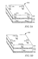
- FIGs. 3A and 3B illustrate two examples of deploying markers' cavities according to an embodiment of the invention in a DSOI wafer. These FIGs. show wafer 300 in which various cavities were etched (but without showing the etched rotor comb).
- the illustrated DSOI wafer comprises a first active layer 310, a second active layer 320, an oxide layer 315 separating between the first and the second active layers, a glass layer 360 bonded to the active layer 310.
- Cavities 350, 353 and two other cavities are used as marker cavities.
- cavities 370, 373, 376 and 379 are etched in the second active layer at locations that essentially match those of marker cavities 350, 373 and the other two marker cavities in the first layer.
- the etching of cavities 370, 373, 376 and 379 is carried out until reaching oxide layer 315. Thereafter, the exact locations of the centers of the marker cavities are identified and compared each with the centers of the respective cavities etched in the second layer. Upon determining the match between the centers of the marker cavities and the second layer cavities, any offset may be calculated and based thereon, the mask for etching the second layer device is prepared.
- FIG. 3B A similar process is described in FIG. 3B where the 4 marker cavities (of which only 350 is shown in this FIG.) and their corresponding cavities of the second layer, are located at different positions to enable different way of obtaining reference points for preparing the mask that would allow etching the second active layer with the required accuracy.
Landscapes
- Physics & Mathematics (AREA)
- Engineering & Computer Science (AREA)
- General Physics & Mathematics (AREA)
- Optics & Photonics (AREA)
- Geometry (AREA)
- Manufacturing & Machinery (AREA)
- Microelectronics & Electronic Packaging (AREA)
- Micromachines (AREA)
- Mechanical Light Control Or Optical Switches (AREA)
Description
- The present invention relates generally to micro opto-electro-mechanical devices and their manufacturing process and more particularly to methods for improving the accuracy of the etching step in the process of manufacturing such devices.
- Nowadays many MOEMS (Micro Optimal Electro-Mechanical Systems) applications use a tilting motion of a deformable element (e.g. element used for tilting micro mirrors). State-of-the-art electrostatic actuating devices are configured with an angular degree of freedom and are driven by electrostatic forces. Electro-static comb drives can be divided to an in-plane comb drive ("IPCD") and vertical comb drive ("VCD").
- The IPCD and VCD actuators are used to generalize the working principle of a double-sided comb-drive actuator and to obtain an angular motion. They are constructed from two sets of combs, a moving part (henceforth rotor) and static part (stator) interlaced together, for example the MOEMS illustrated in
FIGs. 1A and 1B . The use of the two combs forms a free space capacitor, whereas the motion between the two combs changes the capacity of the free-space capacitor thus formed. Accordingly, upon applying a voltage difference between the stator and rotor combs, it induces vertical electrostatic force that creates a motion. However, in addition to the tilt motion, the voltage difference might also produce unwanted vertical and lateral motions of the mirror.FIG. 1C illustrates an example of a schematic cross-sectional view of the pure rotational actuation. In this example the forces that cause vertical and lateral piston motions are canceled by the symmetric layout of the comb stators. The electrostatic forces are generated in the gaps between the combs shown inFIG. 1B . Since the capacity of a capacitor as described above is mainly influenced by its geometric shape, the dimensions of the combs strongly influence the obtained electrostatic force. A larger electrostatic force can be acquired when the aspect ratio increases (the aspect ratio is defined as the ratio between the height of the comb and the distance between every pair of adjacent teeth comprised in the comb). - Several methods are known in the art for fabricating VCD. These prior art methods can generally be segmented to methods for fabricating the VCD from a two device layer wafers, which may be considered as a "self aligned" mode and methods for fabricating each of the combs of the VCD separately, using a different wafer followed by bonding the two (rotor and stator) wafers to create a single VCD. An example of such a self aligned mode for fabricating a VCD is described in
US 6,713,367 . The method described by this publication includes the steps of etching in a semiconductor wafer a first comb with a coarse set of teeth, then a second semiconductor wafer is bonded to the first set of teeth, and another set of teeth is etched in the second wafer with teeth overlapping the teeth in the first comb. Even though both top and bottom comb teeth of the VCD actuator are defined by a single fabrication mask, the difficulty of this method lies in the fact that it highly depends upon the accuracy of the machine to obtain sufficiently accurate alignment. The problems associated with wafers' bonding method are described in length by Jin-Woo Cho et al in "Electrostatic 1D Micro Scanner with Vertical Combs for HD resolution Display", Proc. Of SPIE vol. 6466, (2007). Basically a relative small divergence - (even one that is within the system's tolerance) in aligning both wafers, might result in electric shortage between overlapping comb's teeth. Up to date, current VCD fabrication methods provide VCD having relatively low aspect ratio.
-
US 2005/219677 discloses a MOEMS apparatus manufactured from a double active layer silicon on insulator substrate wherein the stator and rotor fingers are defined by carrying out several etching using the same mask of resist. The resist mask is stripped only for completing definition of the bottom (stator) fingers. - Sun Y et al: "A high-aspect-ration two-axis electrostatic microactuator with extended travel range" Sensors and Actuators A, Elsevier Sequoia S.A. Lausanne CH, col. 102, no. 1-2, 1 December 2002, pages 49-60, discloses DRIE etching for forming high aspect ratio features as small as 2 µm.
-
EP 1 792 870 discloses a manufacturing process wherein buried marks are formed in the intermediate insulating layer and etching of the first and second active layers is performed by etching respective cavities that reveal the respective buried marks. - It is an object of the present invention to provide a method for manufacturing an electro-static comb drive with aspect ratio higher than 1:20.
- It is still another object of the present invention provide a method for manufacturing a MOEMS apparatus that eliminates the possibility for electric shortages due to overlapping combs' teeth.
- It is a yet a further object of the present invention to provide a method of fabricating an electro-static comb drive having small distances between adjacent comb teeth, thereby enabling to achieve high electrostatic force for actuation when using such a device.
- It is still another object of the present invention to provide a fabricating process that allows achieving alignment accuracy that is better than ±0.5µm.
- It is yet another object of the present invention to provide a fabricating process that enables achieving accurate etching through two device layers with unlimited thickness of insulating (oxide) layer therebetween.
- Other objets of this invention will become clear as the description of the invention proceeds.
- According to an aspect of the present invention, there is provided a method for fabricating a MOEMS apparatus from a double active layer silicon on insulator (DSOI) substrate that includes two active layers separated by an insulating layer, the method comprising:
- a. etching in the first active layer a first plurality of designated shapes and at least one cavity adapted to be used as a marker;
- b. etching in the second active layer at least one cavity at a location that essentially corresponds to the location of the at least one cavity that has been etched in the first active layer;
- c. identifying through the at least one cavity etched in the second active layer, the location of the at least one marker cavity etched in the first active layer;
- d. based upon the identification step, determining at least one reference point at the second active layer for etching a second plurality of designated shapes thereat; and
- e. in the second active layer, etching a second plurality of designated shapes located at pre-determined distances from the at least one reference point.
- According to another embodiment of the present invention, etching the plurality of designated shapes and the at least one marker in the first active layer are carried out simultaneously.
- According to another embodiment of the present invention the thickness of the insulating layer (e.g. the oxide layer) that separates the first and second active layers is determined so as to enable light passing through the at least one marker cavity that was etched in the first active layer, to reach the cavity etched in the second active layer.
- According to yet another embodiment of the present invention the method further comprising a step of enlarging the at least one cavity etched in the second active layer, in case that one or more of the at least one marker cavities etched in the first active layer have not been properly identified.
- According to another embodiment of the present invention the at least one marker cavity is included in the first plurality of designated shapes, thereby saving on the need to etch the at least one marker cavity in addition to the etching of that first plurality of designated shapes.
- According to still another embodiment, the method further provided a step of converting the two layers device obtained by etching the first layer and the second layer, into a one layer device, by collapsing these two layers into a one layer device, e.g. by converting a vertical comb drive (VCD) engine into a very high aspect ratio in-plane comb drive (IPCD) engine.
- For a more complete understanding of the present invention, reference is made to the following detailed description taken in conjunction with the accompanying drawings wherein:
-
FIGs. 1A and 1B present a typical MEOMS electro-static comb drive; -
FIG. 1C demonstrates an example of a schematic cross-sectional view of the pure rotation actuation; -
FIG. 1D presents a schematic example of a pre-fabricated DSOI wafer; -
FIGs. 2A to 2F present a schematic side view of the fabrication of the electro-static comb drive; and -
FIGs. 3A and 3B present an example of cavities deployed in a DSOI wafer for use as markers. - The present invention will be better understood and appreciated more fully when taken in conjunction with the accompanying drawings.
- Let us first consider
Fig. 1D which presents a schematic example of a pre-fabricated commercially available double-active-layer SOI (Double Silicon on Insulator, "DSOI")wafer 100, prior to its processing. The DSOI wafer typically comprises either a substrate and two active layers or a substrate and one active layer, wherein the substrate itself is used as one of the two active layers. The active layer(s) and the substrate are bonded together before the starting of the fabrication process. The DSOI presented in this figure has (from bottom to top) a firstactive layer 110, anoxide layer 115, a secondactive layer 120, anoxide layer 125 and asilicon substrate 130. Each of the three semiconductor layers, i.e. firstactive layer 110, secondactive layer 120 andsubstrate 130, is electrically isolated from the other by the respective oxide layer.Oxide layer 115 is located between the first and second active layers, andoxide layer 125 is located between the second active layer and the substrate. Each active layer may have a thickness of few to few tens of microns, whereas the oxide layers are typically narrower than the active layers and their thickness changes from less than a micron to few microns. - The steps of a process used according to the present invention for fabricating a comb structure for vertical comb drive are demonstrated in
Figs. 2A- 2F . As will be appreciated by those skilled in the art, the process exemplified herein is one example of fabricating a comb structure for vertical comb drive out of several processes or certain variations in the process described herein, that can be carried out without departing from the scope of the present invention. - All dimensions of the respective layers and of resulting product of the process should be understood as being illustrative for demonstration purposes only. A
typical wafer 200 is shown inFig. 2A which comprises twoactive layers oxide layers Oxide layer 215 separates the firstactive layer 210 from the secondactive layer 220 whereas asecond oxide layer 225 separates the secondactive layer 220 fromsubstrate 230. - The first step of the process is shown in
Fig. 2B , where the firstactive layer 210 has been etched by applying a dry etch step, or by applying any other suitable process that is known in the art per se, in order to form the teeth ofstator 240. As will be appreciated by those skilled in the art, the present invention should not be considered as being limited to which of the active layers would function as the rotor and which as the stator, although in this exampleactive layer 210 is designated to be the stator andactive layer 220 is designated to be the rotor. During this step, and in addition to etching the stator teeth,markers 250 and 250' are also being etched. Since this Fig, illustrates a view side of the wafer, only two cavities that are adapted to be used as markers are shown. Preferably, more markers' cavities are used (and located on a different longititudal axis), to provide a two dimensional match of the mask to be prepared for the etching of the second active layer. The etching of the markers' cavities is carried out up to the oxide layer and is preferably carried out together with the etching of the stator's teeth. The markers' cavities may be etched at pre-defined locations, but in addition or in the alternative, they may be etched in non pre-determined locations but preferably close to the edges of the first active layer (so as not to interfere with the etching of stator 240). In the next step, shown inFig. 2C , upon etching the markers'cavities 250 and 250' and stator combteeth 240, aglass layer 260 is bonded to the firstactive layer 210. Oncewafer 200 is bonded to theglass layer 260, thesubstrate layer 230 andoxide layer 225 are removed as illustrated inFig. 2D , thereby revealing the secondactive layer 220. The next step is shown inFig. 2E where two cavities (270 and 270') were etched inactive layer 220. These two cavities are centered approximately in places that would match the centers of the markers' cavities etched in the first active layer. According to the present invention, the accuracy in etchingcavities 270 and 270' is not highly important because these cavities are used for providing reference point(s) for etching the second active layer. Oncecavities 270 and 270' are etched, markers'cavities 250 and 250' become visible when viewing them from the top surface of the second active layer, i.e. from the surface of the cavities' top apertures, because theoxide layer 215 is very thin hence it is practically transparent. The next step is illustrated inFig. 2F , where the locations of the markers' cavities are used as reference points for preparing a mask to be used for etchingactive layer 220 in the exact designated places, so that a precise etching of therotor comb teeth 280 is achieved. Applying the suggested method allows fabricating a vertical comb drive with an accuracy that is higher than any accuracy that may be achieved while implementing another fabricating method known in the art. The aspect ratio obtained while using the above method was higher than 1:40 and the accuracy obtained better than ±0.5µm. -
FIGs. 3A and 3B illustrate two examples of deploying markers' cavities according to an embodiment of the invention in a DSOI wafer. These FIGs.show wafer 300 in which various cavities were etched (but without showing the etched rotor comb). The illustrated DSOI wafer, comprises a firstactive layer 310, a secondactive layer 320, anoxide layer 315 separating between the first and the second active layers, aglass layer 360 bonded to theactive layer 310.Cavities cavities marker cavities cavities oxide layer 315. Thereafter, the exact locations of the centers of the marker cavities are identified and compared each with the centers of the respective cavities etched in the second layer. Upon determining the match between the centers of the marker cavities and the second layer cavities, any offset may be calculated and based thereon, the mask for etching the second layer device is prepared. - A similar process is described in
FIG. 3B where the 4 marker cavities (of which only 350 is shown in this FIG.) and their corresponding cavities of the second layer, are located at different positions to enable different way of obtaining reference points for preparing the mask that would allow etching the second active layer with the required accuracy.
Claims (7)
- A method for manufacturing a MOEMS apparatus from a DSOI substrate, whereby DSOI denotes double active layer silicon on insulator, said substrate including two active layers (210, 220; 310, 320) separated by an insulating layer (215; 315), the method comprising:a. etching in said first active layer (210; 310) a first plurality of designated shapes (240) and at least one cavity (250, 205'; 350, 353) adapted to be used as a marker;b. etching in said second active layer (220; 320) at least one cavity (270, 270'; 370-379) at a location that essentially corresponds to a location of said at least one marker cavity (250, 205'; 350, 353) that has been etched in said first active layer (210; 310);c. identifying through said at least one cavity (270, 270' ; 370-379) etched in said second active layer (220; 320), said at least one marker cavity (250, 205'; 350, 353) etched in said first active layer (210; 310);d. based upon the identification step (step c), determining at least one reference point at said second active layer (220; 320); ande. in said second active layer, etching a second plurality of designated shapes (280) each located at a pre-determined distance from said at least one reference point.
- A method according to claim 1, wherein etching said first plurality of designated shapes (240), 353) and said at least one marker cavity (250, 205'; 350) in said first active layer (210; 310) are carried out simultaneously.
- A method according to claim 1, wherein a thickness of said insulating layer (215; 315) separating said first and second active layers (210, 220; 310, 320) is determined to enable light passing through said at least one marker cavity (270, 270'; 370-379) etched in said first active layer, to reach the cavity (270, 270'; 370-379) etched in said second active layer.
- A method according to claim 1, further comprising a step of enlarging said at least one cavity (270, 270'; 370-379) etched in said second active layer (220; 320), in case that one or more of said at least one marker cavity (250, 205'; 350, 353) etched in said first active layer (210; 310) have not been properly identified.
- A method according to claim 1, further comprising a step of converting said two layer device obtained by etching said first active layer (210; 310) and said second active layer (220; 320), into a one layered device.
- A method according to claim 1, wherein said at least one marker cavity (250, 205'; 350, 353) etched in said first active layer (210; 310) is included in said first plurality of designated shapes.
- A method according to claim 1, further comprising a step of collapsing the two layers device obtained by etching said first active layer (210; 310) and said second layer (220; 320), into a one layered device.
Applications Claiming Priority (1)
| Application Number | Priority Date | Filing Date | Title |
|---|---|---|---|
| PCT/IL2009/000516 WO2010137009A1 (en) | 2009-05-24 | 2009-05-24 | A moems apparatus comprising a comb drive and a method for manufacturing same |
Publications (2)
| Publication Number | Publication Date |
|---|---|
| EP2435356A1 EP2435356A1 (en) | 2012-04-04 |
| EP2435356B1 true EP2435356B1 (en) | 2014-01-08 |
Family
ID=41818609
Family Applications (1)
| Application Number | Title | Priority Date | Filing Date |
|---|---|---|---|
| EP09787438.2A Not-in-force EP2435356B1 (en) | 2009-05-24 | 2009-05-24 | A method for manufacturing a MOEMS apparatus having aligned structures in two planes |
Country Status (3)
| Country | Link |
|---|---|
| US (3) | US8305670B2 (en) |
| EP (1) | EP2435356B1 (en) |
| WO (1) | WO2010137009A1 (en) |
Cited By (1)
| Publication number | Priority date | Publication date | Assignee | Title |
|---|---|---|---|---|
| RU2652533C2 (en) * | 2014-02-25 | 2018-04-26 | Нортроп Грумман Литеф Гмбх | Component manufacturing method |
Families Citing this family (3)
| Publication number | Priority date | Publication date | Assignee | Title |
|---|---|---|---|---|
| US9335544B2 (en) * | 2013-03-15 | 2016-05-10 | Rit Wireless Ltd. | Electrostatically steerable actuator |
| US9670056B2 (en) | 2014-01-31 | 2017-06-06 | Stmicroelectronics S.R.L. | Electrostatically driven MEMS device |
| TWI605013B (en) | 2014-07-01 | 2017-11-11 | 村田製作所股份有限公司 | Micro-optical electromechanical scanning device and method for manufacturing it |
Family Cites Families (5)
| Publication number | Priority date | Publication date | Assignee | Title |
|---|---|---|---|---|
| US6713367B2 (en) | 2001-08-28 | 2004-03-30 | The Board Of Trustees Of The Leland Stanford Junior University | Self-aligned vertical combdrive actuator and method of fabrication |
| US7177063B2 (en) | 2003-08-12 | 2007-02-13 | Terraop Ltd. | Bouncing mode operated scanning micro-mirror |
| US7069784B1 (en) * | 2004-12-29 | 2006-07-04 | Honeywell International Inc. | Pendulous in-plane MEMS accelerometer device |
| KR100718141B1 (en) | 2005-12-01 | 2007-05-14 | 삼성전자주식회사 | Double sided etching method with embedded alignment mark |
| WO2009026232A1 (en) | 2007-08-20 | 2009-02-26 | Board Of Regents, The University Of Texas System | Apparatus for performing confocal endoscopy |
-
2009
- 2009-05-24 US US13/320,828 patent/US8305670B2/en not_active Expired - Fee Related
- 2009-05-24 EP EP09787438.2A patent/EP2435356B1/en not_active Not-in-force
- 2009-05-24 WO PCT/IL2009/000516 patent/WO2010137009A1/en not_active Ceased
-
2012
- 2012-10-30 US US13/663,550 patent/US8693074B2/en active Active
-
2014
- 2014-02-06 US US14/174,367 patent/US9459447B2/en active Active
Cited By (2)
| Publication number | Priority date | Publication date | Assignee | Title |
|---|---|---|---|---|
| RU2652533C2 (en) * | 2014-02-25 | 2018-04-26 | Нортроп Грумман Литеф Гмбх | Component manufacturing method |
| RU2652533C9 (en) * | 2014-02-25 | 2018-09-11 | Нортроп Грумман Литеф Гмбх | Component manufacturing method |
Also Published As
| Publication number | Publication date |
|---|---|
| US20120062973A1 (en) | 2012-03-15 |
| US20140153074A1 (en) | 2014-06-05 |
| EP2435356A1 (en) | 2012-04-04 |
| US9459447B2 (en) | 2016-10-04 |
| US20130050793A1 (en) | 2013-02-28 |
| US8693074B2 (en) | 2014-04-08 |
| WO2010137009A1 (en) | 2010-12-02 |
| US8305670B2 (en) | 2012-11-06 |
Similar Documents
| Publication | Publication Date | Title |
|---|---|---|
| US10649202B2 (en) | Micro-electro-mechanical device with a movable structure, in particular micromirror, and manufacturing process thereof | |
| CN111552072B (en) | Large-size MEMS vertical comb micro-mirror and preparation method thereof | |
| US7083997B2 (en) | Bonded wafer optical MEMS process | |
| KR100486716B1 (en) | 2-dimensional actuator and manufacturing method thereof | |
| US7026184B2 (en) | Method of fabricating microstructures and devices made therefrom | |
| CN111538154B (en) | Electrostatic driven MEMS micro-mirror array and preparation method thereof | |
| CN101056072B (en) | Staggered vertical comb driver processing method | |
| US6686639B1 (en) | High performance MEMS device fabricatable with high yield | |
| US7469588B2 (en) | MEMS vertical comb drive with improved vibration performance | |
| US20130181302A1 (en) | Method for making a suspended membrane structure with buried electrode | |
| Hah et al. | A self-aligned vertical comb-drive actuator on an SOI wafer for a 2D scanning micromirror | |
| KR100373739B1 (en) | Method for Fabrication of Electrostatic Vertical Actuators Using One Single-crystalline Silicon Wafer | |
| US20070069604A1 (en) | Mems device comprising an actuator generating a hysteresis driving motion | |
| US9459447B2 (en) | MOEMS apparatus and a method for manufacturing same | |
| US20080186557A1 (en) | Hidden hinge MEMS device | |
| EP1932803B1 (en) | MEMS device with Z-axis asymetry | |
| KR100888080B1 (en) | How to Build a Micromirror Array | |
| CN103596874A (en) | Out-of-plane travel restriction structures | |
| US20150131136A1 (en) | Micromechanical component and method for producing a micromechanical component | |
| Gallagher et al. | A review of fabrication processes for vertical comb drives | |
| CN113671689A (en) | MEMS rotating mirror structure with large mirror surface | |
| CN117776098A (en) | MEMS device, preparation method thereof and MEMS micro-mirror | |
| EP1619164A2 (en) | Vertical offset structure and method for fabricating the same | |
| US9382113B2 (en) | Method for fabricating a self-aligned vertical comb drive structure | |
| Lin et al. | A self-aligned fabrication method of dual comb drive using multilayers SOI process for optical MEMS applications |
Legal Events
| Date | Code | Title | Description |
|---|---|---|---|
| PUAI | Public reference made under article 153(3) epc to a published international application that has entered the european phase |
Free format text: ORIGINAL CODE: 0009012 |
|
| 17P | Request for examination filed |
Effective date: 20111216 |
|
| AK | Designated contracting states |
Kind code of ref document: A1 Designated state(s): AT BE BG CH CY CZ DE DK EE ES FI FR GB GR HR HU IE IS IT LI LT LU LV MC MK MT NL NO PL PT RO SE SI SK TR |
|
| DAX | Request for extension of the european patent (deleted) | ||
| 17Q | First examination report despatched |
Effective date: 20121212 |
|
| RIC1 | Information provided on ipc code assigned before grant |
Ipc: G02B 26/08 20060101ALI20130531BHEP Ipc: B81C 1/00 20060101AFI20130531BHEP |
|
| GRAP | Despatch of communication of intention to grant a patent |
Free format text: ORIGINAL CODE: EPIDOSNIGR1 |
|
| INTG | Intention to grant announced |
Effective date: 20130723 |
|
| GRAS | Grant fee paid |
Free format text: ORIGINAL CODE: EPIDOSNIGR3 |
|
| RAP1 | Party data changed (applicant data changed or rights of an application transferred) |
Owner name: STMICROELECTRONICS INTERNATIONAL N.V. |
|
| GRAA | (expected) grant |
Free format text: ORIGINAL CODE: 0009210 |
|
| RAP1 | Party data changed (applicant data changed or rights of an application transferred) |
Owner name: STMICROELECTRONICS INTERNATIONAL N.V. |
|
| AK | Designated contracting states |
Kind code of ref document: B1 Designated state(s): AT BE BG CH CY CZ DE DK EE ES FI FR GB GR HR HU IE IS IT LI LT LU LV MC MK MT NL NO PL PT RO SE SI SK TR |
|
| REG | Reference to a national code |
Ref country code: GB Ref legal event code: FG4D |
|
| REG | Reference to a national code |
Ref country code: CH Ref legal event code: EP |
|
| REG | Reference to a national code |
Ref country code: IE Ref legal event code: FG4D |
|
| REG | Reference to a national code |
Ref country code: AT Ref legal event code: REF Ref document number: 648617 Country of ref document: AT Kind code of ref document: T Effective date: 20140215 |
|
| REG | Reference to a national code |
Ref country code: DE Ref legal event code: R096 Ref document number: 602009021365 Country of ref document: DE Effective date: 20140220 |
|
| REG | Reference to a national code |
Ref country code: AT Ref legal event code: MK05 Ref document number: 648617 Country of ref document: AT Kind code of ref document: T Effective date: 20140108 |
|
| REG | Reference to a national code |
Ref country code: NL Ref legal event code: VDEP Effective date: 20140108 |
|
| REG | Reference to a national code |
Ref country code: LT Ref legal event code: MG4D |
|
| PG25 | Lapsed in a contracting state [announced via postgrant information from national office to epo] |
Ref country code: NO Free format text: LAPSE BECAUSE OF FAILURE TO SUBMIT A TRANSLATION OF THE DESCRIPTION OR TO PAY THE FEE WITHIN THE PRESCRIBED TIME-LIMIT Effective date: 20140408 Ref country code: IS Free format text: LAPSE BECAUSE OF FAILURE TO SUBMIT A TRANSLATION OF THE DESCRIPTION OR TO PAY THE FEE WITHIN THE PRESCRIBED TIME-LIMIT Effective date: 20140508 Ref country code: LT Free format text: LAPSE BECAUSE OF FAILURE TO SUBMIT A TRANSLATION OF THE DESCRIPTION OR TO PAY THE FEE WITHIN THE PRESCRIBED TIME-LIMIT Effective date: 20140108 |
|
| PG25 | Lapsed in a contracting state [announced via postgrant information from national office to epo] |
Ref country code: SE Free format text: LAPSE BECAUSE OF FAILURE TO SUBMIT A TRANSLATION OF THE DESCRIPTION OR TO PAY THE FEE WITHIN THE PRESCRIBED TIME-LIMIT Effective date: 20140108 Ref country code: CY Free format text: LAPSE BECAUSE OF FAILURE TO SUBMIT A TRANSLATION OF THE DESCRIPTION OR TO PAY THE FEE WITHIN THE PRESCRIBED TIME-LIMIT Effective date: 20140108 Ref country code: FI Free format text: LAPSE BECAUSE OF FAILURE TO SUBMIT A TRANSLATION OF THE DESCRIPTION OR TO PAY THE FEE WITHIN THE PRESCRIBED TIME-LIMIT Effective date: 20140108 Ref country code: AT Free format text: LAPSE BECAUSE OF FAILURE TO SUBMIT A TRANSLATION OF THE DESCRIPTION OR TO PAY THE FEE WITHIN THE PRESCRIBED TIME-LIMIT Effective date: 20140108 Ref country code: ES Free format text: LAPSE BECAUSE OF FAILURE TO SUBMIT A TRANSLATION OF THE DESCRIPTION OR TO PAY THE FEE WITHIN THE PRESCRIBED TIME-LIMIT Effective date: 20140108 Ref country code: PT Free format text: LAPSE BECAUSE OF FAILURE TO SUBMIT A TRANSLATION OF THE DESCRIPTION OR TO PAY THE FEE WITHIN THE PRESCRIBED TIME-LIMIT Effective date: 20140508 Ref country code: NL Free format text: LAPSE BECAUSE OF FAILURE TO SUBMIT A TRANSLATION OF THE DESCRIPTION OR TO PAY THE FEE WITHIN THE PRESCRIBED TIME-LIMIT Effective date: 20140108 |
|
| PG25 | Lapsed in a contracting state [announced via postgrant information from national office to epo] |
Ref country code: BE Free format text: LAPSE BECAUSE OF FAILURE TO SUBMIT A TRANSLATION OF THE DESCRIPTION OR TO PAY THE FEE WITHIN THE PRESCRIBED TIME-LIMIT Effective date: 20140108 Ref country code: LV Free format text: LAPSE BECAUSE OF FAILURE TO SUBMIT A TRANSLATION OF THE DESCRIPTION OR TO PAY THE FEE WITHIN THE PRESCRIBED TIME-LIMIT Effective date: 20140108 Ref country code: HR Free format text: LAPSE BECAUSE OF FAILURE TO SUBMIT A TRANSLATION OF THE DESCRIPTION OR TO PAY THE FEE WITHIN THE PRESCRIBED TIME-LIMIT Effective date: 20140108 |
|
| REG | Reference to a national code |
Ref country code: DE Ref legal event code: R097 Ref document number: 602009021365 Country of ref document: DE |
|
| PG25 | Lapsed in a contracting state [announced via postgrant information from national office to epo] |
Ref country code: DK Free format text: LAPSE BECAUSE OF FAILURE TO SUBMIT A TRANSLATION OF THE DESCRIPTION OR TO PAY THE FEE WITHIN THE PRESCRIBED TIME-LIMIT Effective date: 20140108 Ref country code: CZ Free format text: LAPSE BECAUSE OF FAILURE TO SUBMIT A TRANSLATION OF THE DESCRIPTION OR TO PAY THE FEE WITHIN THE PRESCRIBED TIME-LIMIT Effective date: 20140108 Ref country code: EE Free format text: LAPSE BECAUSE OF FAILURE TO SUBMIT A TRANSLATION OF THE DESCRIPTION OR TO PAY THE FEE WITHIN THE PRESCRIBED TIME-LIMIT Effective date: 20140108 Ref country code: RO Free format text: LAPSE BECAUSE OF FAILURE TO SUBMIT A TRANSLATION OF THE DESCRIPTION OR TO PAY THE FEE WITHIN THE PRESCRIBED TIME-LIMIT Effective date: 20140108 |
|
| PLBE | No opposition filed within time limit |
Free format text: ORIGINAL CODE: 0009261 |
|
| STAA | Information on the status of an ep patent application or granted ep patent |
Free format text: STATUS: NO OPPOSITION FILED WITHIN TIME LIMIT |
|
| PG25 | Lapsed in a contracting state [announced via postgrant information from national office to epo] |
Ref country code: PL Free format text: LAPSE BECAUSE OF FAILURE TO SUBMIT A TRANSLATION OF THE DESCRIPTION OR TO PAY THE FEE WITHIN THE PRESCRIBED TIME-LIMIT Effective date: 20140108 Ref country code: SK Free format text: LAPSE BECAUSE OF FAILURE TO SUBMIT A TRANSLATION OF THE DESCRIPTION OR TO PAY THE FEE WITHIN THE PRESCRIBED TIME-LIMIT Effective date: 20140108 |
|
| 26N | No opposition filed |
Effective date: 20141009 |
|
| PG25 | Lapsed in a contracting state [announced via postgrant information from national office to epo] |
Ref country code: LU Free format text: LAPSE BECAUSE OF FAILURE TO SUBMIT A TRANSLATION OF THE DESCRIPTION OR TO PAY THE FEE WITHIN THE PRESCRIBED TIME-LIMIT Effective date: 20140524 |
|
| REG | Reference to a national code |
Ref country code: CH Ref legal event code: PL |
|
| REG | Reference to a national code |
Ref country code: DE Ref legal event code: R097 Ref document number: 602009021365 Country of ref document: DE Effective date: 20141009 |
|
| GBPC | Gb: european patent ceased through non-payment of renewal fee |
Effective date: 20140524 |
|
| PG25 | Lapsed in a contracting state [announced via postgrant information from national office to epo] |
Ref country code: CH Free format text: LAPSE BECAUSE OF NON-PAYMENT OF DUE FEES Effective date: 20140531 Ref country code: MC Free format text: LAPSE BECAUSE OF FAILURE TO SUBMIT A TRANSLATION OF THE DESCRIPTION OR TO PAY THE FEE WITHIN THE PRESCRIBED TIME-LIMIT Effective date: 20140108 Ref country code: LI Free format text: LAPSE BECAUSE OF NON-PAYMENT OF DUE FEES Effective date: 20140531 |
|
| REG | Reference to a national code |
Ref country code: IE Ref legal event code: MM4A |
|
| REG | Reference to a national code |
Ref country code: FR Ref legal event code: ST Effective date: 20150130 |
|
| PG25 | Lapsed in a contracting state [announced via postgrant information from national office to epo] |
Ref country code: IE Free format text: LAPSE BECAUSE OF NON-PAYMENT OF DUE FEES Effective date: 20140524 |
|
| PG25 | Lapsed in a contracting state [announced via postgrant information from national office to epo] |
Ref country code: GB Free format text: LAPSE BECAUSE OF NON-PAYMENT OF DUE FEES Effective date: 20140524 Ref country code: FR Free format text: LAPSE BECAUSE OF NON-PAYMENT OF DUE FEES Effective date: 20140602 Ref country code: SI Free format text: LAPSE BECAUSE OF FAILURE TO SUBMIT A TRANSLATION OF THE DESCRIPTION OR TO PAY THE FEE WITHIN THE PRESCRIBED TIME-LIMIT Effective date: 20140108 |
|
| PG25 | Lapsed in a contracting state [announced via postgrant information from national office to epo] |
Ref country code: MT Free format text: LAPSE BECAUSE OF FAILURE TO SUBMIT A TRANSLATION OF THE DESCRIPTION OR TO PAY THE FEE WITHIN THE PRESCRIBED TIME-LIMIT Effective date: 20140108 |
|
| PG25 | Lapsed in a contracting state [announced via postgrant information from national office to epo] |
Ref country code: IT Free format text: LAPSE BECAUSE OF FAILURE TO SUBMIT A TRANSLATION OF THE DESCRIPTION OR TO PAY THE FEE WITHIN THE PRESCRIBED TIME-LIMIT Effective date: 20140108 Ref country code: BG Free format text: LAPSE BECAUSE OF FAILURE TO SUBMIT A TRANSLATION OF THE DESCRIPTION OR TO PAY THE FEE WITHIN THE PRESCRIBED TIME-LIMIT Effective date: 20140108 Ref country code: GR Free format text: LAPSE BECAUSE OF FAILURE TO SUBMIT A TRANSLATION OF THE DESCRIPTION OR TO PAY THE FEE WITHIN THE PRESCRIBED TIME-LIMIT Effective date: 20140409 |
|
| PG25 | Lapsed in a contracting state [announced via postgrant information from national office to epo] |
Ref country code: TR Free format text: LAPSE BECAUSE OF FAILURE TO SUBMIT A TRANSLATION OF THE DESCRIPTION OR TO PAY THE FEE WITHIN THE PRESCRIBED TIME-LIMIT Effective date: 20140108 Ref country code: HU Free format text: LAPSE BECAUSE OF FAILURE TO SUBMIT A TRANSLATION OF THE DESCRIPTION OR TO PAY THE FEE WITHIN THE PRESCRIBED TIME-LIMIT; INVALID AB INITIO Effective date: 20090524 |
|
| REG | Reference to a national code |
Ref country code: DE Ref legal event code: R082 Ref document number: 602009021365 Country of ref document: DE Representative=s name: SCHMITT-NILSON SCHRAUD WAIBEL WOHLFROM PATENTA, DE |
|
| PG25 | Lapsed in a contracting state [announced via postgrant information from national office to epo] |
Ref country code: MK Free format text: LAPSE BECAUSE OF FAILURE TO SUBMIT A TRANSLATION OF THE DESCRIPTION OR TO PAY THE FEE WITHIN THE PRESCRIBED TIME-LIMIT Effective date: 20140108 |
|
| PGFP | Annual fee paid to national office [announced via postgrant information from national office to epo] |
Ref country code: DE Payment date: 20230419 Year of fee payment: 15 |
|
| REG | Reference to a national code |
Ref country code: DE Ref legal event code: R119 Ref document number: 602009021365 Country of ref document: DE |
|
| PG25 | Lapsed in a contracting state [announced via postgrant information from national office to epo] |
Ref country code: DE Free format text: LAPSE BECAUSE OF NON-PAYMENT OF DUE FEES Effective date: 20241203 |