EP2434925B1 - Method for fabricating an applicator tip assembly for a skin formulation applicator - Google Patents
Method for fabricating an applicator tip assembly for a skin formulation applicator Download PDFInfo
- Publication number
- EP2434925B1 EP2434925B1 EP10781064.0A EP10781064A EP2434925B1 EP 2434925 B1 EP2434925 B1 EP 2434925B1 EP 10781064 A EP10781064 A EP 10781064A EP 2434925 B1 EP2434925 B1 EP 2434925B1
- Authority
- EP
- European Patent Office
- Prior art keywords
- casting
- fixture
- applicator
- base portion
- tip
- Prior art date
- Legal status (The legal status is an assumption and is not a legal conclusion. Google has not performed a legal analysis and makes no representation as to the accuracy of the status listed.)
- Active
Links
Images

Classifications
-
- A—HUMAN NECESSITIES
- A45—HAND OR TRAVELLING ARTICLES
- A45D—HAIRDRESSING OR SHAVING EQUIPMENT; EQUIPMENT FOR COSMETICS OR COSMETIC TREATMENTS, e.g. FOR MANICURING OR PEDICURING
- A45D34/00—Containers or accessories specially adapted for handling liquid toiletry or cosmetic substances, e.g. perfumes
- A45D34/04—Appliances specially adapted for applying liquid, e.g. using roller or ball
-
- B—PERFORMING OPERATIONS; TRANSPORTING
- B29—WORKING OF PLASTICS; WORKING OF SUBSTANCES IN A PLASTIC STATE IN GENERAL
- B29C—SHAPING OR JOINING OF PLASTICS; SHAPING OF MATERIAL IN A PLASTIC STATE, NOT OTHERWISE PROVIDED FOR; AFTER-TREATMENT OF THE SHAPED PRODUCTS, e.g. REPAIRING
- B29C39/00—Shaping by casting, i.e. introducing the moulding material into a mould or between confining surfaces without significant moulding pressure; Apparatus therefor
- B29C39/02—Shaping by casting, i.e. introducing the moulding material into a mould or between confining surfaces without significant moulding pressure; Apparatus therefor for making articles of definite length, i.e. discrete articles
- B29C39/021—Shaping by casting, i.e. introducing the moulding material into a mould or between confining surfaces without significant moulding pressure; Apparatus therefor for making articles of definite length, i.e. discrete articles by casting in several steps
-
- B—PERFORMING OPERATIONS; TRANSPORTING
- B29—WORKING OF PLASTICS; WORKING OF SUBSTANCES IN A PLASTIC STATE IN GENERAL
- B29C—SHAPING OR JOINING OF PLASTICS; SHAPING OF MATERIAL IN A PLASTIC STATE, NOT OTHERWISE PROVIDED FOR; AFTER-TREATMENT OF THE SHAPED PRODUCTS, e.g. REPAIRING
- B29C39/00—Shaping by casting, i.e. introducing the moulding material into a mould or between confining surfaces without significant moulding pressure; Apparatus therefor
- B29C39/02—Shaping by casting, i.e. introducing the moulding material into a mould or between confining surfaces without significant moulding pressure; Apparatus therefor for making articles of definite length, i.e. discrete articles
- B29C39/10—Shaping by casting, i.e. introducing the moulding material into a mould or between confining surfaces without significant moulding pressure; Apparatus therefor for making articles of definite length, i.e. discrete articles incorporating preformed parts or layers, e.g. casting around inserts or for coating articles
-
- A—HUMAN NECESSITIES
- A45—HAND OR TRAVELLING ARTICLES
- A45D—HAIRDRESSING OR SHAVING EQUIPMENT; EQUIPMENT FOR COSMETICS OR COSMETIC TREATMENTS, e.g. FOR MANICURING OR PEDICURING
- A45D40/00—Casings or accessories specially adapted for storing or handling solid or pasty toiletry or cosmetic substances, e.g. shaving soaps or lipsticks
- A45D40/0068—Jars
- A45D40/0075—Jars with dispensing means
Definitions
- This invention relates generally to appliances for applying skin treatment formulations to the facial area of the human body, and more particularly concerns an article and method for fabricating an applicator tip assembly used in such an appliance.
- the document US4919949A discloses a container for storage of refrigerated dough products under pressurized conditions.
- the document US4496070 discloses a disposable mould for making a test sample of set concrete.
- a single-use casting fixture which includes a casting section and a tear-away section, the casting section including a rim portion adapted to receive a base portion of an applicator tip assembly part, the casting section having an interior volume beneath the rim portion to receive flowable casting material suitable for contact with facial skin area of a user for application of skin formulations, wherein the silicone material fills the interior volume and when cured to solid form bonds to extending elements from the base portion, forming a firm engagement therewith, wherein the resulting combination of the casting fixture and the applicator tip assembly part can be stored until ready for use, and wherein the tear-away section permits convenient removal of the part from the casting fixture.
- the invention is a method for casting a tip portion of a tip applicator assembly used in a skin formulation applicator, wherein the tip portion is mated with a base portion of the tip applicator during casting, the method comprising the steps of: positioning the base portion of a tip applicator assembly in a casting fixture, the casting fixture including a cup section for receiving the base portion and at least one tear-away section, the casting fixture comprising a material which is readily separable from and will not adhere to the casting material comprising the tip portion of the part following casting thereof; pouring the casting material into a volume in the cup section beneath the positioned base portion, the casting material engaging and bonding to an extending part of the base portion; and allowing the casting material to cure, such that the base portion and the tip portion form a cohesive whole, wherein the casting fixture with the cast part therein can be stored until the tip applicator assembly is ready for use.
- Figure 1 shows an example of an appliance part 10 which is fashioned using the casting article and the fabrication method disclosed herein.
- part 10 is an applicator tip assembly used in an appliance for applying skin formulations to the facial area of the skin.
- the applicator tip assembly 10 is described in more detail in co-pending application Serial No. 12/474,426 assigned to the same assignee as the present invention.
- the applicator tip assembly 10 includes a tip portion 12 which makes physical contact with the user in operation of the applicator.
- the tip portion 12 must be very soft and, in one example, is approximately Shore scale OO Durometer 30.
- the applicator tip assembly 10 also includes a base portion 14 which is sufficiently rigid to be conveniently installed and removed from a drive end portion of the applicator motor.
- there are difficulties using conventional casting fixtures to produce the described applicator tip assembly because of the very different characteristics of base portion 14 and tip portion 12. These difficulties include high fixture costs to obtain high volumes of production, difficulties in removing the cast parts from the fixture, and keeping the resulting parts clean until delivery to the end user.
- Casting fixture 16 is a single use fixture, made from lubricious material such as low-density polyethylene.
- Casting fixture 16 includes a central cup-like section 18 and two opposing side tear-off wing sections 20 and 22.
- the wing sections include tear-off lines 24 which extend down the side of the cup section 18.
- the tear-off lines 24 are thinner than the remainder of the fixture.
- the thinned sections are approximately 0.005 inches thick, while the remainder of the casting fixture 16 is typically approximately 0.030 inches thick, although this can vary.
- the size of the fixture can also vary depending upon the part to be cast.
- the cup section 18 is approximately 0.300 inches high and 0.500 inches in diameter.
- the two wing sections 20 and 22 are approximately 0.600 inches long and extend directly outwardly from cup section 18.
- Each wing section includes a generally circular outer/outboard portion 28 and a narrower inner/inboard portion 30 which connects the outer portion to cup section 18.
- Each outer portion includes a small rim 32 along a portion of its periphery in order to facilitate tear-away of the wing sections.
- Top edge 34 of cup section 18 includes a lip 36 which extends around portions of the top edge 34 between the edges of inner portions 30 of the wing sections 20 and 22.
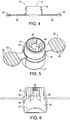
- a rigid base portion 14 with an outer wall 42 is positioned in fixture 16 such that a small outwardly extending portion 39 of upper edge 40 (shown inverted in Figure 6 ) of wall 42 can be snapped into lip 36 of cup section 18. This is shown most clearly in Figures 5 and 6 , which also show ribs 45-45 on the upper surface of wing sections 20 and 22. This leaves an interior volume 37 within cup section 18 beneath base portion 14.
- Silicone or other similar material 43 in liquid form, is poured through base portion 14 into the interior volume 37 of the cup section of the casting fixture. Sufficient material is provided to interior volume 37 that the material extends a small distance into the interior of base portion 14, as shown in Figure 6 .
- the engagement members 50-50 are partially encapsulated by the silicone material. This provides a reliable, strong connection between the silicone material, which defines the soft tip portion of the applicator assembly, and the more rigid base portion, with the rigid base portion providing the required reliable, strong attachment capability to a drive end of the applicator motor.
- the casting fixture shown herein is single use, as indicated above. After the cup is filled with silicon, it is allowed to cure in the casting fixture and then stored. The casting fixture with the part therein can be shipped directly to consumers. When an applicator assembly is to be replaced, the user simply tears away the strips 20 and 22 from the new assembly and the cast silicone tip portion comes away easily and cleanly from the casting fixture. The applicator assembly is then installed onto the drive end of the applicator motor. The casting fixture is then disposed of.
- the casting fixture disclosed above has several advantages, including its simplicity and low cost.
- the consumer can easily and readily remove the assembly from the fixture and install it.
- the part comes away cleanly from the fixture with the aid of the tear-away strips.
- the fixture arrangement also ensures that the part remains clean when it is provided to the user for replacement of existing parts.
Landscapes
- Engineering & Computer Science (AREA)
- Mechanical Engineering (AREA)
- Coating Apparatus (AREA)
- Casting Or Compression Moulding Of Plastics Or The Like (AREA)
- Media Introduction/Drainage Providing Device (AREA)
- Materials For Medical Uses (AREA)
Description
- This invention relates generally to appliances for applying skin treatment formulations to the facial area of the human body, and more particularly concerns an article and method for fabricating an applicator tip assembly used in such an appliance.
- Many parts used in small personal appliances, such as skin formulation applicators, are made by casting methods using a mold/fixture. It is important to control the cost of the cast parts to ensure product success in the marketplace. The cost of the mold and the details of the casting process are both important in controlling costs. The casting process can be slow and requires a large quantity of mold cavities, which are generally expensive, in order to meet high volume manufacturing requirements. In addition, problems may be encountered in removing cast parts from the fixtures, especially low durometer silicone parts. Further, the silicone parts can often be tacky after they have been removed from the cavity, requiring special handling techniques to ensure that the parts remain clean when they are provided to the user for replacement of existing parts. Still further, parts comprising low durometer silicone are difficult to attach directly to other elements, such as a drive end of a motor, after they have been cured and otherwise ready for use.
- The document
US4919949A discloses a container for storage of refrigerated dough products under pressurized conditions. The documentUS4496070 discloses a disposable mould for making a test sample of set concrete. - Hence, there is a need for both a casting fixture and a method of casting particular parts which are used in skin formulation applicators, to reliably produce clean parts inexpensively and to firmly affix the parts to a companion part during the casting process to produce a desired combination/assembly for the applicator.
- One example useful for understanding the invention is an article for casting parts, comprising: a single-use casting fixture which includes a casting section and a tear-away section, the casting section including a rim portion adapted to receive a base portion of an applicator tip assembly part, the casting section having an interior volume beneath the rim portion to receive flowable casting material suitable for contact with facial skin area of a user for application of skin formulations, wherein the silicone material fills the interior volume and when cured to solid form bonds to extending elements from the base portion, forming a firm engagement therewith, wherein the resulting combination of the casting fixture and the applicator tip assembly part can be stored until ready for use, and wherein the tear-away section permits convenient removal of the part from the casting fixture.
- The invention is a method for casting a tip portion of a tip applicator assembly used in a skin formulation applicator, wherein the tip portion is mated with a base portion of the tip applicator during casting, the method comprising the steps of: positioning the base portion of a tip applicator assembly in a casting fixture, the casting fixture including a cup section for receiving the base portion and at least one tear-away section, the casting fixture comprising a material which is readily separable from and will not adhere to the casting material comprising the tip portion of the part following casting thereof; pouring the casting material into a volume in the cup section beneath the positioned base portion, the casting material engaging and bonding to an extending part of the base portion; and allowing the casting material to cure, such that the base portion and the tip portion form a cohesive whole, wherein the casting fixture with the cast part therein can be stored until the tip applicator assembly is ready for use.
-
-
Figure 1 is an isometric view of an applicator tip assembly which is produced by use of the fabrication method disclosed herein. -
Figure 2 is a perspective view of the casting fixture disclosed herein. -
Figure 3 is a top view of the casting fixture ofFigure 2 . -
Figure 4 is a side elevational view of the casting fixture ofFigures 2 and 3 . -
Figure 5 is a perspective view of a casting fixture similar toFigures 2-4 with an applicator tip assembly received in position thereon. -
Figure 6 is a cross-sectional view showing the casting fixture ofFigure 5 , following filling of the casting fixture with silicone or similar material. -
Figure 1 shows an example of an appliance part 10 which is fashioned using the casting article and the fabrication method disclosed herein. In this example, part 10 is an applicator tip assembly used in an appliance for applying skin formulations to the facial area of the skin. The applicator tip assembly 10 is described in more detail in co-pending application Serial No.12/474,426 - Briefly, the applicator tip assembly 10 includes a
tip portion 12 which makes physical contact with the user in operation of the applicator. Thetip portion 12 must be very soft and, in one example, is approximately Shorescale OO Durometer 30. The applicator tip assembly 10 also includes abase portion 14 which is sufficiently rigid to be conveniently installed and removed from a drive end portion of the applicator motor. As indicated above, there are difficulties using conventional casting fixtures to produce the described applicator tip assembly because of the very different characteristics ofbase portion 14 andtip portion 12. These difficulties include high fixture costs to obtain high volumes of production, difficulties in removing the cast parts from the fixture, and keeping the resulting parts clean until delivery to the end user. - The present casting fixture is shown in
Figures 2-6 . Castingfixture 16 is a single use fixture, made from lubricious material such as low-density polyethylene.Casting fixture 16 includes a central cup-like section 18 and two opposing side tear-offwing sections lines 24 which extend down the side of thecup section 18. The tear-offlines 24 are thinner than the remainder of the fixture. The thinned sections are approximately 0.005 inches thick, while the remainder of thecasting fixture 16 is typically approximately 0.030 inches thick, although this can vary. The size of the fixture can also vary depending upon the part to be cast. In the embodiment shown, thecup section 18 is approximately 0.300 inches high and 0.500 inches in diameter. The twowing sections cup section 18. Each wing section includes a generally circular outer/outboard portion 28 and a narrower inner/inboard portion 30 which connects the outer portion tocup section 18. Each outer portion includes asmall rim 32 along a portion of its periphery in order to facilitate tear-away of the wing sections.Top edge 34 ofcup section 18 includes alip 36 which extends around portions of thetop edge 34 between the edges ofinner portions 30 of thewing sections - In the casting process, a
rigid base portion 14 with anouter wall 42 is positioned infixture 16 such that a small outwardly extendingportion 39 of upper edge 40 (shown inverted inFigure 6 ) ofwall 42 can be snapped intolip 36 ofcup section 18. This is shown most clearly inFigures 5 and 6 , which also show ribs 45-45 on the upper surface ofwing sections interior volume 37 withincup section 18 beneathbase portion 14. - In this process, the bottom of
base portion 14, which mates with a drive end of the applicator motor, as disclosed in detail in the '426 application, extends above the top of the casting fixture. Elements 44-44 ofbase portion 14 provide a capability of mating with the drive end of the applicator motor. Various arrangements to accomplish this result, however, are possible and are not a part of the present invention. Engagement member(s) 50, which in the embodiment shown could be a cylindrical member, or separate arcuate elements, extends downwardly intointerior volume 37 of the cup section. The actual casting of the applicator assembly part now begins. - Silicone or other
similar material 43, in liquid form, is poured throughbase portion 14 into theinterior volume 37 of the cup section of the casting fixture. Sufficient material is provided tointerior volume 37 that the material extends a small distance into the interior ofbase portion 14, as shown inFigure 6 . The engagement members 50-50 are partially encapsulated by the silicone material. This provides a reliable, strong connection between the silicone material, which defines the soft tip portion of the applicator assembly, and the more rigid base portion, with the rigid base portion providing the required reliable, strong attachment capability to a drive end of the applicator motor. - The casting fixture shown herein is single use, as indicated above. After the cup is filled with silicon, it is allowed to cure in the casting fixture and then stored. The casting fixture with the part therein can be shipped directly to consumers. When an applicator assembly is to be replaced, the user simply tears away the
strips - The casting fixture disclosed above has several advantages, including its simplicity and low cost. The consumer can easily and readily remove the assembly from the fixture and install it. The part comes away cleanly from the fixture with the aid of the tear-away strips. The fixture arrangement also ensures that the part remains clean when it is provided to the user for replacement of existing parts.
- Although a preferred embodiment has been disclosed for purposes of illustration, it should be understood that various changes and modifications and substitutions could be made in the preferred embodiment without departing from the scope of the invention as defined by the appended claims.
Claims (7)
- A method for casting a tip portion (12) of a tip applicator assembly (10) used in a skin formulation applicator, wherein the tip portion is mated with a base portion (14) of the tip applicator during casting, the method comprising the steps of:positioning the base portion of the tip applicator assembly in a casting fixture (16), the casting fixture including a cup section (18) for receiving the base portion and at least one tear- away section (20,22), the casting fixture comprising a material which is readily separable from and will not adhere to the casting material comprising the tip portion of the part following casting thereof;pouring the casting material into a volume (37) in the cup section beneath the positioned base portion, the casting material engaging and bonding to an extending part of the base portion; andallowing the casting material to cure, such that the base portion and the tip portion form a cohesive whole, wherein the casting fixture with the cast part therein can be stored until the tip applicator assembly is ready for use.
- The method of claim 1, wherein the casting material is silicone (43).
- The method of claim 2, wherein the silicone material is Shore scale OO Durometer 30.
- The method of clam 1, wherein the casting fixture includes two tear- away sections (20,22) extending from opposing ends of the cup section.
- The method of claim 1 wherein the casting fixture material is lubricious.
- The method of claim 4, wherein the tear-away sections are thinner than adjacent portions of the cup section.
- The method of claim 2, wherein the silicone material is characterized by a lack of a bonding with the cup section of the fixture during casting.
Applications Claiming Priority (2)
| Application Number | Priority Date | Filing Date | Title |
|---|---|---|---|
| US12/474,518 US8272862B2 (en) | 2009-05-29 | 2009-05-29 | Article and method for fabricating an applicator tip assembly for a skin formulation applicator |
| PCT/US2010/035978 WO2010138461A1 (en) | 2009-05-29 | 2010-05-24 | Article and method for fabricating an applicator tip assembly for a skin formulation applicator |
Publications (3)
| Publication Number | Publication Date |
|---|---|
| EP2434925A1 EP2434925A1 (en) | 2012-04-04 |
| EP2434925A4 EP2434925A4 (en) | 2018-01-03 |
| EP2434925B1 true EP2434925B1 (en) | 2019-08-14 |
Family
ID=43219319
Family Applications (1)
| Application Number | Title | Priority Date | Filing Date |
|---|---|---|---|
| EP10781064.0A Active EP2434925B1 (en) | 2009-05-29 | 2010-05-24 | Method for fabricating an applicator tip assembly for a skin formulation applicator |
Country Status (9)
| Country | Link |
|---|---|
| US (1) | US8272862B2 (en) |
| EP (1) | EP2434925B1 (en) |
| JP (1) | JP5834005B2 (en) |
| KR (1) | KR101729347B1 (en) |
| CN (1) | CN102458184B (en) |
| AU (1) | AU2010254264B2 (en) |
| CA (1) | CA2763902C (en) |
| SG (1) | SG176282A1 (en) |
| WO (1) | WO2010138461A1 (en) |
Families Citing this family (10)
| Publication number | Priority date | Publication date | Assignee | Title |
|---|---|---|---|---|
| USD742647S1 (en) | 2013-08-28 | 2015-11-10 | L'oreal Usa Creative, Inc. | Powered brush handle |
| USD715555S1 (en) | 2013-08-28 | 2014-10-21 | L'oreal Usa Creative, Inc. | Combined powered brush handle, brush head, and charger |
| USD715554S1 (en) | 2013-08-28 | 2014-10-21 | L'oreal Usa Creative, Inc. | Combined powered brush handle and brush head |
| USD715558S1 (en) | 2013-08-29 | 2014-10-21 | L'oreal Usa Creative, Inc. | Brush head |
| USD715557S1 (en) | 2013-08-29 | 2014-10-21 | L'oreal Usa Creative, Inc. | Brush head |
| USD715556S1 (en) | 2013-08-29 | 2014-10-21 | L'oreal Usa Creative, Inc. | Brush head |
| US10022025B2 (en) | 2016-05-20 | 2018-07-17 | Chirp Products, LLC | Dual motor cleansing brush |
| US11241083B2 (en) | 2017-07-13 | 2022-02-08 | Chirp Products, LLC | Cleansing brush head |
| USD864577S1 (en) | 2018-06-27 | 2019-10-29 | Fka Distributing Co., Llc | Skin care brush and massager |
| FR3097728B1 (en) * | 2019-06-28 | 2025-03-28 | Oreal | Device for sampling and applying a cosmetic composition |
Family Cites Families (38)
| Publication number | Priority date | Publication date | Assignee | Title |
|---|---|---|---|---|
| US875944A (en) * | 1906-03-31 | 1908-01-07 | Mary A Nash | Pan. |
| US1258209A (en) * | 1915-02-11 | 1918-03-05 | Emil Gathmann | Ingot-mold. |
| US1833858A (en) * | 1929-07-03 | 1931-11-24 | Samuel J Roberts | Ink well and attachment |
| US2166587A (en) * | 1938-06-01 | 1939-07-18 | Gathmann Res Inc | Ingot mold and ingot |
| US2716250A (en) * | 1952-08-27 | 1955-08-30 | Ever Dry Corp | Dispenser and dispensing head constructed to deliver the contents of a container to a fabric for saturation |
| US3429096A (en) * | 1965-02-12 | 1969-02-25 | Ekco Containers Inc | Method of making an applicator package |
| CA1078125A (en) * | 1975-11-11 | 1980-05-27 | Francis S. Crock | Apparatus for the construction of a domed structure such as an igloo |
| US4225254A (en) * | 1977-03-17 | 1980-09-30 | Holberg Steven E | Surgical scrub system |
| US4124141A (en) * | 1977-07-11 | 1978-11-07 | Armentrout James L | Sterile container |
| US4496070A (en) * | 1982-09-29 | 1985-01-29 | Lane Jr Samuel H | Container and lid forming a disposable mold |
| DK149152C (en) * | 1983-07-28 | 1986-09-15 | Jens Ove Nielsen | SALES PACKAGING OF THE DUNK OR BATTERY TYPE, AND LOW AND SAFETY CLOSES |
| US4940158A (en) * | 1987-09-22 | 1990-07-10 | American National Can Company | Container and seam ring for container |
| US4919949A (en) * | 1988-10-06 | 1990-04-24 | The Pillsbury Co. | Refrigerated dough container |
| NL8803215A (en) * | 1988-12-30 | 1990-07-16 | Crellin Bv | PLASTIC CHEESE VESSEL WITH CLAMPS COMPATIBLE WITH PLASTIC CHEESE VESSELS. |
| GB9021406D0 (en) * | 1990-10-02 | 1990-11-14 | Foseco Int | Hot top lining assembly for ingot moulds |
| DE59207974D1 (en) * | 1991-04-30 | 1997-03-13 | Kuhn Heinrich Metall | Metal tableware |
| DE69420178T2 (en) * | 1993-04-27 | 2000-03-09 | Sakura Color Products Corp. | Liquid application device and manufacture of the same |
| FR2706747B1 (en) * | 1993-06-25 | 1996-02-09 | Oreal | |
| US5507406A (en) * | 1994-04-26 | 1996-04-16 | Belford Patrick, Inc. | Tamperproof/tamper evident container |
| FR2799940B1 (en) * | 1999-10-22 | 2001-12-28 | Oreal | FOAM APPLICATOR COMPRISING ONE OR MORE PARTICULATE COMPOUNDS CONCENTRATE IN THE SURROUNDING AREA OF THE APPLICATION |
| FR2820010B1 (en) * | 2001-02-01 | 2003-04-04 | Oreal | DEVICE FOR PACKAGING AND APPLYING A PRODUCT |
| US6616364B2 (en) * | 2001-03-16 | 2003-09-09 | Robert Katz | Convertible surface contacting implement |
| US7044938B2 (en) * | 2002-07-17 | 2006-05-16 | La Bianco Kerrie L | Skin treatment apparatus and methods |
| US6688795B1 (en) * | 2002-11-06 | 2004-02-10 | E-L Management Corp. | Applicator package with disposable applicator pad assembly |
| US6910608B2 (en) * | 2002-11-12 | 2005-06-28 | Homax Products, Inc. | Storage systems and methods for aerosol accessories |
| US6883692B2 (en) * | 2002-11-20 | 2005-04-26 | Honda Giken Kogyo Kabushiki Kaisha | Sauce holder for fold out arm rest |
| JP2005245989A (en) * | 2004-03-02 | 2005-09-15 | Taiyo Kurihara | Electric beauty treatment apparatus |
| FR2870696B1 (en) * | 2004-05-27 | 2006-09-01 | Oreal | DEVICE FOR PACKAGING AND APPLYING A PRODUCT |
| US7335188B2 (en) * | 2004-06-12 | 2008-02-26 | Graf Christian D | Lumbar puncture fluid collection device |
| EP1623651A1 (en) * | 2004-08-06 | 2006-02-08 | Schwan-STABILO Cosmetics GmbH & Co. KG | Applicator and method for producing an applicator |
| FR2875110B1 (en) * | 2004-09-10 | 2006-12-22 | Oreal | DEVICE FOR APPLYING A PRODUCT PROVIDED WITH A REMOVABLE APPLICATION MEMBER |
| US7273086B2 (en) * | 2004-10-26 | 2007-09-25 | Alcoa Inc. | Lubricant for improved surface quality of cast aluminum and method |
| DE502005004882D1 (en) * | 2005-05-10 | 2008-09-11 | Dentaco Gmbh | Once dispensing device |
| US20070045329A1 (en) * | 2005-08-29 | 2007-03-01 | Te-Shun Yeh | Cup having a burn-preventing apparatus |
| US7786626B2 (en) * | 2006-11-03 | 2010-08-31 | Pacific Bioscience Laboratories, Inc. | Oscillating motor for a personal care appliance |
| US7878123B2 (en) * | 2007-04-13 | 2011-02-01 | Jason Jackson | Single rail film dolly and slider |
| US8469909B2 (en) * | 2009-05-29 | 2013-06-25 | L'oreal, Sa | Motor for a personal skin care appliance |
| US9763508B2 (en) * | 2009-05-29 | 2017-09-19 | L'oreal | Applicator tip assembly for skin formulation applicator |
-
2009
- 2009-05-29 US US12/474,518 patent/US8272862B2/en not_active Expired - Fee Related
-
2010
- 2010-05-24 SG SG2011088085A patent/SG176282A1/en unknown
- 2010-05-24 AU AU2010254264A patent/AU2010254264B2/en not_active Ceased
- 2010-05-24 WO PCT/US2010/035978 patent/WO2010138461A1/en not_active Ceased
- 2010-05-24 CA CA2763902A patent/CA2763902C/en not_active Expired - Fee Related
- 2010-05-24 CN CN201080032949.XA patent/CN102458184B/en not_active Expired - Fee Related
- 2010-05-24 EP EP10781064.0A patent/EP2434925B1/en active Active
- 2010-05-24 KR KR1020117031293A patent/KR101729347B1/en not_active Expired - Fee Related
- 2010-05-24 JP JP2012513161A patent/JP5834005B2/en not_active Expired - Fee Related
Non-Patent Citations (1)
| Title |
|---|
| None * |
Also Published As
| Publication number | Publication date |
|---|---|
| KR101729347B1 (en) | 2017-05-02 |
| EP2434925A1 (en) | 2012-04-04 |
| AU2010254264A1 (en) | 2011-12-22 |
| CA2763902C (en) | 2017-02-28 |
| KR20120024870A (en) | 2012-03-14 |
| SG176282A1 (en) | 2012-01-30 |
| EP2434925A4 (en) | 2018-01-03 |
| US20100301520A1 (en) | 2010-12-02 |
| CA2763902A1 (en) | 2010-12-02 |
| US8272862B2 (en) | 2012-09-25 |
| AU2010254264B2 (en) | 2015-10-01 |
| CN102458184A (en) | 2012-05-16 |
| WO2010138461A1 (en) | 2010-12-02 |
| CN102458184B (en) | 2014-11-05 |
| JP5834005B2 (en) | 2015-12-16 |
| JP2012527963A (en) | 2012-11-12 |
| HK1170643A1 (en) | 2013-03-08 |
Similar Documents
| Publication | Publication Date | Title |
|---|---|---|
| CA2763902C (en) | Article and method for fabricating an applicator tip assembly for a skin formulation applicator | |
| US11980274B2 (en) | Lip balm applicator | |
| US20180255906A1 (en) | Cosmetic container | |
| KR102420172B1 (en) | Shaping method of solid cosmetic material | |
| CN1129393A (en) | Food packaging method and related manufacturing components | |
| CN114615910B (en) | Packaging Deodorant Stick Products | |
| CN113347903A (en) | Packaging deodorant stick products | |
| GB2197778A (en) | Manufacture of confection | |
| WO2013079069A1 (en) | Spread container | |
| US20080143018A1 (en) | Process for the preparation of a poured cosmetic product with a superficial relief | |
| CN107207117B (en) | A cup-shaped container for moulded food and method for releasing moulded food by means of aeration device | |
| HK1170643B (en) | Article and method for fabricating an applicator tip assembly for a skin formulation applicator | |
| US10919686B2 (en) | Plastic container for food product having a plurality of frangible vent holes | |
| KR20180123232A (en) | Capsule type ice cream container with discharge hole stopper | |
| US20100282861A1 (en) | Disposable pod and battery operated chocolate fountain | |
| JP3413593B2 (en) | Container filling device | |
| EP3821756A1 (en) | Blister package having applicator therein | |
| KR20170110373A (en) | Reusable cosmetic vessel | |
| JP5783782B2 (en) | Container with applicator | |
| KR20160125258A (en) | Ice cream extrusion apparatus | |
| JP2014162481A (en) | Method for charging with viscous material and charger of the same | |
| HK1228697B (en) | Lip balm with spherical surface and method for producing | |
| JPH0537099U (en) | Elastic mold |
Legal Events
| Date | Code | Title | Description |
|---|---|---|---|
| PUAI | Public reference made under article 153(3) epc to a published international application that has entered the european phase |
Free format text: ORIGINAL CODE: 0009012 |
|
| 17P | Request for examination filed |
Effective date: 20111128 |
|
| AK | Designated contracting states |
Kind code of ref document: A1 Designated state(s): AL AT BE BG CH CY CZ DE DK EE ES FI FR GB GR HR HU IE IS IT LI LT LU LV MC MK MT NL NO PL PT RO SE SI SK SM TR |
|
| DAX | Request for extension of the european patent (deleted) | ||
| RAP1 | Party data changed (applicant data changed or rights of an application transferred) |
Owner name: L'OREAL, S.A. |
|
| RA4 | Supplementary search report drawn up and despatched (corrected) |
Effective date: 20171130 |
|
| RIC1 | Information provided on ipc code assigned before grant |
Ipc: A45D 33/16 20060101AFI20171124BHEP |
|
| GRAP | Despatch of communication of intention to grant a patent |
Free format text: ORIGINAL CODE: EPIDOSNIGR1 |
|
| STAA | Information on the status of an ep patent application or granted ep patent |
Free format text: STATUS: GRANT OF PATENT IS INTENDED |
|
| INTG | Intention to grant announced |
Effective date: 20190129 |
|
| RIN1 | Information on inventor provided before grant (corrected) |
Inventor name: PILCHER, KENNETH A. Inventor name: REISHUS, RICHARD A. Inventor name: HERLIN, GREGORY W. |
|
| GRAS | Grant fee paid |
Free format text: ORIGINAL CODE: EPIDOSNIGR3 |
|
| GRAJ | Information related to disapproval of communication of intention to grant by the applicant or resumption of examination proceedings by the epo deleted |
Free format text: ORIGINAL CODE: EPIDOSDIGR1 |
|
| GRAL | Information related to payment of fee for publishing/printing deleted |
Free format text: ORIGINAL CODE: EPIDOSDIGR3 |
|
| STAA | Information on the status of an ep patent application or granted ep patent |
Free format text: STATUS: REQUEST FOR EXAMINATION WAS MADE |
|
| GRAR | Information related to intention to grant a patent recorded |
Free format text: ORIGINAL CODE: EPIDOSNIGR71 |
|
| STAA | Information on the status of an ep patent application or granted ep patent |
Free format text: STATUS: GRANT OF PATENT IS INTENDED |
|
| GRAA | (expected) grant |
Free format text: ORIGINAL CODE: 0009210 |
|
| STAA | Information on the status of an ep patent application or granted ep patent |
Free format text: STATUS: THE PATENT HAS BEEN GRANTED |
|
| INTC | Intention to grant announced (deleted) | ||
| INTG | Intention to grant announced |
Effective date: 20190704 |
|
| AK | Designated contracting states |
Kind code of ref document: B1 Designated state(s): AL AT BE BG CH CY CZ DE DK EE ES FI FR GB GR HR HU IE IS IT LI LT LU LV MC MK MT NL NO PL PT RO SE SI SK SM TR |
|
| REG | Reference to a national code |
Ref country code: GB Ref legal event code: FG4D |
|
| REG | Reference to a national code |
Ref country code: CH Ref legal event code: EP Ref country code: AT Ref legal event code: REF Ref document number: 1165983 Country of ref document: AT Kind code of ref document: T Effective date: 20190815 |
|
| REG | Reference to a national code |
Ref country code: IE Ref legal event code: FG4D |
|
| REG | Reference to a national code |
Ref country code: DE Ref legal event code: R096 Ref document number: 602010060576 Country of ref document: DE |
|
| REG | Reference to a national code |
Ref country code: NL Ref legal event code: MP Effective date: 20190814 |
|
| REG | Reference to a national code |
Ref country code: LT Ref legal event code: MG4D |
|
| PG25 | Lapsed in a contracting state [announced via postgrant information from national office to epo] |
Ref country code: FI Free format text: LAPSE BECAUSE OF FAILURE TO SUBMIT A TRANSLATION OF THE DESCRIPTION OR TO PAY THE FEE WITHIN THE PRESCRIBED TIME-LIMIT Effective date: 20190814 Ref country code: NO Free format text: LAPSE BECAUSE OF FAILURE TO SUBMIT A TRANSLATION OF THE DESCRIPTION OR TO PAY THE FEE WITHIN THE PRESCRIBED TIME-LIMIT Effective date: 20191114 Ref country code: NL Free format text: LAPSE BECAUSE OF FAILURE TO SUBMIT A TRANSLATION OF THE DESCRIPTION OR TO PAY THE FEE WITHIN THE PRESCRIBED TIME-LIMIT Effective date: 20190814 Ref country code: HR Free format text: LAPSE BECAUSE OF FAILURE TO SUBMIT A TRANSLATION OF THE DESCRIPTION OR TO PAY THE FEE WITHIN THE PRESCRIBED TIME-LIMIT Effective date: 20190814 Ref country code: BG Free format text: LAPSE BECAUSE OF FAILURE TO SUBMIT A TRANSLATION OF THE DESCRIPTION OR TO PAY THE FEE WITHIN THE PRESCRIBED TIME-LIMIT Effective date: 20191114 Ref country code: SE Free format text: LAPSE BECAUSE OF FAILURE TO SUBMIT A TRANSLATION OF THE DESCRIPTION OR TO PAY THE FEE WITHIN THE PRESCRIBED TIME-LIMIT Effective date: 20190814 Ref country code: PT Free format text: LAPSE BECAUSE OF FAILURE TO SUBMIT A TRANSLATION OF THE DESCRIPTION OR TO PAY THE FEE WITHIN THE PRESCRIBED TIME-LIMIT Effective date: 20191216 Ref country code: LT Free format text: LAPSE BECAUSE OF FAILURE TO SUBMIT A TRANSLATION OF THE DESCRIPTION OR TO PAY THE FEE WITHIN THE PRESCRIBED TIME-LIMIT Effective date: 20190814 |
|
| REG | Reference to a national code |
Ref country code: AT Ref legal event code: MK05 Ref document number: 1165983 Country of ref document: AT Kind code of ref document: T Effective date: 20190814 |
|
| PG25 | Lapsed in a contracting state [announced via postgrant information from national office to epo] |
Ref country code: AL Free format text: LAPSE BECAUSE OF FAILURE TO SUBMIT A TRANSLATION OF THE DESCRIPTION OR TO PAY THE FEE WITHIN THE PRESCRIBED TIME-LIMIT Effective date: 20190814 Ref country code: LV Free format text: LAPSE BECAUSE OF FAILURE TO SUBMIT A TRANSLATION OF THE DESCRIPTION OR TO PAY THE FEE WITHIN THE PRESCRIBED TIME-LIMIT Effective date: 20190814 Ref country code: GR Free format text: LAPSE BECAUSE OF FAILURE TO SUBMIT A TRANSLATION OF THE DESCRIPTION OR TO PAY THE FEE WITHIN THE PRESCRIBED TIME-LIMIT Effective date: 20191115 Ref country code: IS Free format text: LAPSE BECAUSE OF FAILURE TO SUBMIT A TRANSLATION OF THE DESCRIPTION OR TO PAY THE FEE WITHIN THE PRESCRIBED TIME-LIMIT Effective date: 20191214 Ref country code: ES Free format text: LAPSE BECAUSE OF FAILURE TO SUBMIT A TRANSLATION OF THE DESCRIPTION OR TO PAY THE FEE WITHIN THE PRESCRIBED TIME-LIMIT Effective date: 20190814 |
|
| PG25 | Lapsed in a contracting state [announced via postgrant information from national office to epo] |
Ref country code: TR Free format text: LAPSE BECAUSE OF FAILURE TO SUBMIT A TRANSLATION OF THE DESCRIPTION OR TO PAY THE FEE WITHIN THE PRESCRIBED TIME-LIMIT Effective date: 20190814 |
|
| PG25 | Lapsed in a contracting state [announced via postgrant information from national office to epo] |
Ref country code: IT Free format text: LAPSE BECAUSE OF FAILURE TO SUBMIT A TRANSLATION OF THE DESCRIPTION OR TO PAY THE FEE WITHIN THE PRESCRIBED TIME-LIMIT Effective date: 20190814 Ref country code: RO Free format text: LAPSE BECAUSE OF FAILURE TO SUBMIT A TRANSLATION OF THE DESCRIPTION OR TO PAY THE FEE WITHIN THE PRESCRIBED TIME-LIMIT Effective date: 20190814 Ref country code: PL Free format text: LAPSE BECAUSE OF FAILURE TO SUBMIT A TRANSLATION OF THE DESCRIPTION OR TO PAY THE FEE WITHIN THE PRESCRIBED TIME-LIMIT Effective date: 20190814 Ref country code: DK Free format text: LAPSE BECAUSE OF FAILURE TO SUBMIT A TRANSLATION OF THE DESCRIPTION OR TO PAY THE FEE WITHIN THE PRESCRIBED TIME-LIMIT Effective date: 20190814 Ref country code: EE Free format text: LAPSE BECAUSE OF FAILURE TO SUBMIT A TRANSLATION OF THE DESCRIPTION OR TO PAY THE FEE WITHIN THE PRESCRIBED TIME-LIMIT Effective date: 20190814 Ref country code: AT Free format text: LAPSE BECAUSE OF FAILURE TO SUBMIT A TRANSLATION OF THE DESCRIPTION OR TO PAY THE FEE WITHIN THE PRESCRIBED TIME-LIMIT Effective date: 20190814 |
|
| PG25 | Lapsed in a contracting state [announced via postgrant information from national office to epo] |
Ref country code: CZ Free format text: LAPSE BECAUSE OF FAILURE TO SUBMIT A TRANSLATION OF THE DESCRIPTION OR TO PAY THE FEE WITHIN THE PRESCRIBED TIME-LIMIT Effective date: 20190814 Ref country code: IS Free format text: LAPSE BECAUSE OF FAILURE TO SUBMIT A TRANSLATION OF THE DESCRIPTION OR TO PAY THE FEE WITHIN THE PRESCRIBED TIME-LIMIT Effective date: 20200224 Ref country code: SM Free format text: LAPSE BECAUSE OF FAILURE TO SUBMIT A TRANSLATION OF THE DESCRIPTION OR TO PAY THE FEE WITHIN THE PRESCRIBED TIME-LIMIT Effective date: 20190814 Ref country code: SK Free format text: LAPSE BECAUSE OF FAILURE TO SUBMIT A TRANSLATION OF THE DESCRIPTION OR TO PAY THE FEE WITHIN THE PRESCRIBED TIME-LIMIT Effective date: 20190814 |
|
| REG | Reference to a national code |
Ref country code: DE Ref legal event code: R097 Ref document number: 602010060576 Country of ref document: DE |
|
| PLBE | No opposition filed within time limit |
Free format text: ORIGINAL CODE: 0009261 |
|
| STAA | Information on the status of an ep patent application or granted ep patent |
Free format text: STATUS: NO OPPOSITION FILED WITHIN TIME LIMIT |
|
| PG2D | Information on lapse in contracting state deleted |
Ref country code: IS |
|
| PGFP | Annual fee paid to national office [announced via postgrant information from national office to epo] |
Ref country code: DE Payment date: 20200512 Year of fee payment: 11 Ref country code: FR Payment date: 20200414 Year of fee payment: 11 |
|
| 26N | No opposition filed |
Effective date: 20200603 |
|
| PG25 | Lapsed in a contracting state [announced via postgrant information from national office to epo] |
Ref country code: SI Free format text: LAPSE BECAUSE OF FAILURE TO SUBMIT A TRANSLATION OF THE DESCRIPTION OR TO PAY THE FEE WITHIN THE PRESCRIBED TIME-LIMIT Effective date: 20190814 |
|
| PGFP | Annual fee paid to national office [announced via postgrant information from national office to epo] |
Ref country code: GB Payment date: 20200513 Year of fee payment: 11 |
|
| PG25 | Lapsed in a contracting state [announced via postgrant information from national office to epo] |
Ref country code: MC Free format text: LAPSE BECAUSE OF FAILURE TO SUBMIT A TRANSLATION OF THE DESCRIPTION OR TO PAY THE FEE WITHIN THE PRESCRIBED TIME-LIMIT Effective date: 20190814 Ref country code: CH Free format text: LAPSE BECAUSE OF NON-PAYMENT OF DUE FEES Effective date: 20200531 Ref country code: LI Free format text: LAPSE BECAUSE OF NON-PAYMENT OF DUE FEES Effective date: 20200531 |
|
| REG | Reference to a national code |
Ref country code: BE Ref legal event code: MM Effective date: 20200531 |
|
| PG25 | Lapsed in a contracting state [announced via postgrant information from national office to epo] |
Ref country code: LU Free format text: LAPSE BECAUSE OF NON-PAYMENT OF DUE FEES Effective date: 20200524 |
|
| PG25 | Lapsed in a contracting state [announced via postgrant information from national office to epo] |
Ref country code: IE Free format text: LAPSE BECAUSE OF NON-PAYMENT OF DUE FEES Effective date: 20200524 |
|
| PG25 | Lapsed in a contracting state [announced via postgrant information from national office to epo] |
Ref country code: BE Free format text: LAPSE BECAUSE OF NON-PAYMENT OF DUE FEES Effective date: 20200531 |
|
| REG | Reference to a national code |
Ref country code: DE Ref legal event code: R119 Ref document number: 602010060576 Country of ref document: DE |
|
| GBPC | Gb: european patent ceased through non-payment of renewal fee |
Effective date: 20210524 |
|
| PG25 | Lapsed in a contracting state [announced via postgrant information from national office to epo] |
Ref country code: GB Free format text: LAPSE BECAUSE OF NON-PAYMENT OF DUE FEES Effective date: 20210524 Ref country code: DE Free format text: LAPSE BECAUSE OF NON-PAYMENT OF DUE FEES Effective date: 20211201 |
|
| PG25 | Lapsed in a contracting state [announced via postgrant information from national office to epo] |
Ref country code: MT Free format text: LAPSE BECAUSE OF FAILURE TO SUBMIT A TRANSLATION OF THE DESCRIPTION OR TO PAY THE FEE WITHIN THE PRESCRIBED TIME-LIMIT Effective date: 20190814 Ref country code: FR Free format text: LAPSE BECAUSE OF NON-PAYMENT OF DUE FEES Effective date: 20210531 Ref country code: CY Free format text: LAPSE BECAUSE OF FAILURE TO SUBMIT A TRANSLATION OF THE DESCRIPTION OR TO PAY THE FEE WITHIN THE PRESCRIBED TIME-LIMIT Effective date: 20190814 |
|
| PG25 | Lapsed in a contracting state [announced via postgrant information from national office to epo] |
Ref country code: MK Free format text: LAPSE BECAUSE OF FAILURE TO SUBMIT A TRANSLATION OF THE DESCRIPTION OR TO PAY THE FEE WITHIN THE PRESCRIBED TIME-LIMIT Effective date: 20190814 |