EP2434835A1 - Coordinated multi-point transmission COMP data and signalling on X2-interface using additional VLAN identifier - Google Patents
Coordinated multi-point transmission COMP data and signalling on X2-interface using additional VLAN identifier Download PDFInfo
- Publication number
- EP2434835A1 EP2434835A1 EP10178477A EP10178477A EP2434835A1 EP 2434835 A1 EP2434835 A1 EP 2434835A1 EP 10178477 A EP10178477 A EP 10178477A EP 10178477 A EP10178477 A EP 10178477A EP 2434835 A1 EP2434835 A1 EP 2434835A1
- Authority
- EP
- European Patent Office
- Prior art keywords
- network
- data
- protocol
- base station
- ethernet
- Prior art date
- Legal status (The legal status is an assumption and is not a legal conclusion. Google has not performed a legal analysis and makes no representation as to the accuracy of the status listed.)
- Granted
Links
Images




Classifications
-
- H—ELECTRICITY
- H04—ELECTRIC COMMUNICATION TECHNIQUE
- H04W—WIRELESS COMMUNICATION NETWORKS
- H04W92/00—Interfaces specially adapted for wireless communication networks
- H04W92/16—Interfaces between hierarchically similar devices
- H04W92/20—Interfaces between hierarchically similar devices between access points
-
- H—ELECTRICITY
- H04—ELECTRIC COMMUNICATION TECHNIQUE
- H04B—TRANSMISSION
- H04B7/00—Radio transmission systems, i.e. using radiation field
- H04B7/02—Diversity systems; Multi-antenna system, i.e. transmission or reception using multiple antennas
- H04B7/022—Site diversity; Macro-diversity
- H04B7/024—Co-operative use of antennas of several sites, e.g. in co-ordinated multipoint or co-operative multiple-input multiple-output [MIMO] systems
-
- H—ELECTRICITY
- H04—ELECTRIC COMMUNICATION TECHNIQUE
- H04L—TRANSMISSION OF DIGITAL INFORMATION, e.g. TELEGRAPHIC COMMUNICATION
- H04L12/00—Data switching networks
- H04L12/28—Data switching networks characterised by path configuration, e.g. LAN [Local Area Networks] or WAN [Wide Area Networks]
- H04L12/46—Interconnection of networks
- H04L12/4641—Virtual LANs, VLANs, e.g. virtual private networks [VPN]
- H04L12/4645—Details on frame tagging
-
- H—ELECTRICITY
- H04—ELECTRIC COMMUNICATION TECHNIQUE
- H04W—WIRELESS COMMUNICATION NETWORKS
- H04W72/00—Local resource management
- H04W72/20—Control channels or signalling for resource management
- H04W72/27—Control channels or signalling for resource management between access points
-
- H—ELECTRICITY
- H04—ELECTRIC COMMUNICATION TECHNIQUE
- H04W—WIRELESS COMMUNICATION NETWORKS
- H04W8/00—Network data management
- H04W8/26—Network addressing or numbering for mobility support
-
- H—ELECTRICITY
- H04—ELECTRIC COMMUNICATION TECHNIQUE
- H04W—WIRELESS COMMUNICATION NETWORKS
- H04W88/00—Devices specially adapted for wireless communication networks, e.g. terminals, base stations or access point devices
- H04W88/08—Access point devices
Definitions
- the invention provides a mobile communication method and system in a network using coordinated multipoint, CoMP, transmission, the network comprising at least one base station serving a plurality of mobile terminals.
- feeder link data for each mobile terminal are transmitted using Ethernet protocol; shared data between base stations involved in the CoMP transmission is exchanged using Ethernet protocol; and downlink channel state information, CSI, measured by each mobile terminal is transmitted to the serving base station also using Ethernet protocol.
- Fig. 1 the evolution of interference reduction schemes from the second to the fourth generation of mobile networks is shown.
- 2G: GSM the same frequency is reused only in distant cells. This simple scheme is called frequency reuse.
- the signal strength is naturally reduced as a function of distance, and in this way, much less interference is received in the cell of interest.
- Interference-aware scheduling is a cross-layer (PHY and MAC) optimization, and may be one of the last innovation steps of 3G technology.
- the CSI is used to perform joint signal processing for all the data streams intended for all terminals served in all cells at the CU.
- the goal of this processing is also sketched in the figure, i.e. the desired signals interfere constructively while the interference from the other base station interferes destructively.
- One prerequisite is that all BS transmit coherently, which means that the phase must not change within the coherence time.
- Coherent transmission is more easily realized using a centralized architecture at first sight.
- MIMO algorithms which can be used for cooperative joint transmission with non-cooperative, distributed receivers.
- the information theoretic limit is achieved by the so-called Costa theorem [11] stating that if interference is perfectly known already at the transmitter, ideally, all interference can be removed and a performance can be achieved as in an isolated cell (see reference [6]).
- Practical schemes, such as joint zero forcing or block- diagonal transmission may be less efficient but it is possible to achieve already a large fraction of the potential CoMP gains if the interference is removed prior to the transmission.
- the centralized architecture however, has several practical drawbacks.
- Radio frequency signals are centrally generated and modulated onto a laser diode, transmitted over fiber and recovered using a photodiode.
- RoF technology is highly developed. There are problems at high RF frequencies where the modulation transfer function of the laser diode is reduced and the signal is distorted.
- Optical modulation using a Mach-Zender Interferometer (MZI) is still possible at higher RF frequencies but very costly in practice. Having multiple sectors with multiple antennas per sector at one site implies that multiple RF signals need to be transmitted over the same fiber. This can be done by using wavelength-division multiplexing (WDM). Although this is technically feasible, dedicated optical WDM multiplexers and de-multiplexers for each link from the CU to each base station may be very costly. Multiplexing in the electrical domain costs less.
- Phase noise is a general drawback of distributed baseband-to-RF conversion applied in RRHs. Even if the carrier frequencies are locked to the CPRI or OBSAI symbol clock, phase noise at distributed radio heads is uncorrelated.
- the RF phase shall be constant during the coherence interval (given by the time needed in the feedback loop for multi-cell channel estimation, feedback and application of the joint pre-coder). Realistic values are in the order of 10 ms for LTE. This condition imposes high requirements for local oscillators (LO) at distributed radio heads, compared to previous mobile networks where phase variations are tracked for the serving base station on a time scale below 1 ms.
- LO local oscillators
- phase noise is reduced by -20 dBc/Hz if we go from 10 kHz to 100 kHz offset from the carrier. If we increase the coherence interval by a factor of 10 this is equivalent to slowed down the phase variation by a factor of 10. Rescaling the frequency axis enables us to estimate that, for coherent CoMP in the downlink, the phase noise at the base station LOs shall be 20 dB lower than for LTE.
- Transmitting quantized baseband waveforms over fiber means also that the backhaul traffic is multiplied compared to the data rate.
- the corresponding factor is given by the resolution of the DA converter output, e.g. 12 bits per I and Q signal gives 24 bits per sample and per antenna.
- the maximum data rate on the feeder network (S1) is specified in the order of 300 Mbit/s for a 20 MHz carrier.
- the required data rate on each of the links in a star network from the CU to one base station is 30.72*10 6 Hz*4*24 bit ⁇ 3 Gbit/s.
- the distributed architecture will be described in the following.
- Fig. 3 For implementation in mobile networks, the distributed architecture shown in Fig. 3 has been proposed (see references [12], [13], [14]). This architecture has several advantages in the view of network operator's requirements. First of all, all processing is situated in the serving base station being able to exchange information with other base stations. Furthermore, the networking between the base stations shall be based on flat, IP based architecture using standard low-cost Ethernet equipment. Finally, not all but a limited set of base stations transmit data jointly to multiple terminals in their cells ( Fig. 3a ). Performance evaluation shows that rather than defining fixed sets, the cooperating set should be selected dynamically depending on the position of the terminals. By reducing the set size, complexity, feedback overhead and backhaul traffic are reduced. Of course, the larger the set, the better is the performance.
- BSs are synchronized in a distribuzted manner e.g. by using a global time and phase-locked frequency references with low phase noise derived from the global positioning system (GPS).
- GPS global positioning system
- BS exchange data and CSI needed over the backhaul network.
- CSI and data shall be exchanged rapidly, to minimize feedback delays and to reduce the latency in the network. So they are exchanged over the direct X2 link in the backhaul, see Fig. 3b .
- X2 is a low-latency signalling network, see [15].
- SAE system architecture evolution
- the BS then applies the the local set of rows from the overall weight matrix to perform the locally relevant linear combination of all data streams needed to compute the particular waveforms transmitted from the local antennas.
- the corresponding matrix-vector multiplication is of smaller size, compared to the centralized concept. I.e. for the data preprocessing, the same effort is needed as in the centralitzed concept. Waveforms are transmitted over the air and they interfere constructively for the desired signal and destructively for the unwanted interference.
- the invention providers a mobile communication method in a network using coordinated multipoint, CoMP, transmission, the network comprising at least one base station serving a plurality of mobile terminals, wherein each network data and signaling packet to be exchanged within the cooperation cluster is tagged with an additional identifier defining the set of base stations in the cluster.
- the network data packets are preferably Ethernet data packets, and each Ethernet data packet is preferably tagged with a Virtual Local Area Networks, VLAN, group number (VLAN identifier, VID).
- VLAN Virtual Local Area Networks
- VID Virtual Local Area Networks
- the network protocol may be Ethernet protocol or multicast IP protocol or any other group networking protocol and the identifiers are VLAN tags, IP multicast addresses or any other identifier for the networking group, respectively, being assigned over a wireless downlink control channel to the terminals and used within the group for organizing the data flows.
- feeder link data for each mobile terminal are transmitted using a network protocol; shared data between base stations involved in the CoMP transmission is exchanged using the same network protocol; and downlink channel state information, CSI, measured by each mobile terminal is transmitted to the serving base station using the same network protocol.
- the network protocol may be Ethernet or IP multicasting.
- the mobile communication method in a network using coordinated multipoint, CoMP, transmission, the network comprising at least one base station serving a plurality of mobile terminals, wherein feeder link data for each mobile terminal are transmitted using a network protocol; shared data between base stations involved in the CoMP transmission is exchanged using the same network protocol; and downlink channel state information, CSI, measured by each mobile terminal is transmitted to the serving base station using the same network protocol.
- the data flow for a given terminal over the S1 link from the advanced gateway, aGW is terminated at the serving master base station enhanced NodeB, eNB, and, data are then packed into transport blocks, encoded and mapped onto the radio bearer, RB, and after the MAC layer, the already mapped and encoded data are copied and the copy is forwarded over the X2 interface to all base stations involved in the CoMP transmission.
- the channel state information, CSI, fed back from each terminal to the serving base may be provided as frequency-domain feedback only for those RBs likely to be assigned to a user.
- the channel state information, CSI, fed back from each terminal to the serving base is provided in the delay domain.
- the channel state information, CSI, fed back from each terminal to the serving base using preferably Ethernet or IP protocol, is transmitted in parallel to the uplink user data.
- the packets are formed so that a terminal always packs the entire multi-cell channel matrix in a given sub-band in one packet.
- each network data packet is tagged with an additional identifier.
- each Ethernet data packet is tagged with a Virtual Local Area Networks, VLAN, group number.
- each IP data packet contains a multicast address as a group number. The VLAN group number is located in the packet at the position being used, in untagged frames, by the EtherType/Size field.
- a mobile communication system in a network using coordinated multipoint, CoMP, transmission comprising at least one base station serving a plurality of mobile terminals, the system being characterized in that each network data and signaling packet to be exchanged within the cooperation cluster is tagged with an additional identifier defining the set of base stations in the cluster.
- the network data packets may be Ethernet data packets, and wherein each Ethernet data packet is tagged with a Virtual Local Area Networks, VLAN, group number.
- a mobile communication system in a network using coordinated multipoint, CoMP, transmission comprising at least one base station serving a plurality of mobile terminals, wherein feeder link data for each mobile terminal are transmitted using a network protocol; the bases stations involved in the CoMP transmission are adapted to exchange shared data between themselves using the same network protocol; and each mobile terminal is adapted to transmit measured downlink channel state information, CSI, to the serving base station using the same network protocol.
- each network data packet is tagged with an additional identifier.
- the network protocol may be the Ethernet protocol, and wherein each Ethernet data packet is tagged with a Virtual Local Area Networks, VLAN, group number.
- the network protocol is the Internet protocol, and wherein the IP packet has a multicast address.
- the invention also provides a base station in a mobile communication system in a network using coordinated multipoint, CoMP, transmission, the network comprising at least one base station serving a plurality of mobile terminals, wherein the base station is adapted to receive feeder link data for each mobile terminal using Ethernet protocol; is adapted to exchange shared data with other base stations using Ethernet protocol; and is adapted to receive from each mobile terminal it serves measured downlink channel state information, CSI, using Ethernet protocol.
- the invention also provides a base station in a mobile communication system in a network using coordinated multipoint, CoMP, transmission, the network comprising at least one base station serving a plurality of mobile terminals, wherein the base station is adapted to receive feeder link data for each mobile terminal using IP protocol; is adapted to exchange shared data with other base stations using IP protocol; and is adapted to receive from each mobile terminal it serves measured downlink channel state information, CSI, using IP protocol.
- the base station comprises a VLAN-enabled Ethernet switch capable of doing packet-switching depending on the VLAN identifier.
- the base station comprises a multicast-enabled IP router capable of doing IP packet switching based on the multi-cast address.
- the invention's general approach is that all these streams are organized using the classical Ethernet protocol so that low-cost networking equipment can be used for the backhaul.
- Feeder data are intended for the mobile terminal served by the base station.
- the feeder data are organized in IP packets and transmitted over the S1 interface. Normally, such traffic is transported over Ethernet anyway.
- data are transmitted in a first hop over S1 from the aGW to the serving eNB.
- Data are then packed into transport blocks, encoded and mapped onto the radio bearer, RB.
- the MAC layer we copy these already mapped and encoded data and forward the copy in a second hop over X2 to all base stations involved in the CoMP transmission.
- the invention has the advantage that data bits, and not IQ samples, are exchanged between the base stations.
- the load in the backhaul is significantly reduced in this way.
- it is easier to synchronize the data at all BS at this stage in the transmission chain where all network and MAC layer processing is already completed.
- retransmissions are also controlled locally and need no additional coordination between the BS.
- the X2 interface does not introduce to much latency, the delay due to data exchange is easily compensated using buffers at the precoder inputs.
- the third stream is the multi-cell channel state information, CSI, fed back from each terminal to the serving base.
- CSI channel state information
- the provision of feedback causes a significant overhead and several techniques are suited to minimize the feedback overhead. Firstly, one may provide frequency-domain feedback only for those RBs likely to be assigned to a user. This divides the amount of feedback provided by each terminal by the number of terminals in a cell, in case of a fully loaded cell.
- a second alternative is to feedback the channel in the delay domain, instead of in the frequency domain. I.e. one would in principle Fourier-transform the channel, estimate the most relevant taps and feed back to the BS a list of the complex tap amplitudes and their delays.
- this subband is a contiguous aggregation of sub-carriers.
- the terminal estimates the most relevant taps and their delays and sends them back to the base station.
- the invention propose to send such feedback as Ethernet packets over the air, in parallel to the uplink user data. These packets are formed so that a terminal always packs the entire multi-cell channel matrix in a given sub-band in one packet with or without prior compression. Such packets are fed out of the receiver signal processing chain using a dedicated Ethernet port marked as "CSI" at the terminal.
- Ethernet packets increases the implementation effort at first sight but it enables many new opportunities for the organization of the mobile network.
- the invention provides a powerful measurement interface which may even be used at the application layer, e.g. to switch the transmission quality of a video stream depending on the instantanous channel state.
- the invention enables a simple and powerful method to organize the feeder data, CSI and shared data flows in the backhaul of the cooperative base station system.
- the concept can be extended to more than two base stations and subgroups of base stations can be selected in a very flexible manner for the purpose of cooperative transmission. Furthermore it is ensured that not more data are passed through the network than actually needed.
- the signaling network is shown in Fig. 6 for two cooperative base stations. It relies on widely available low-cost equipment for the IEEE802.3 Ethernet standard. Furthermore, the invention takes profit of an existing standard extension, namely the so-called Virtual Local Area Networks, VLANs, described in IEEE 802.1q. VLANs are based on a packet-switching technique which requires the use of an additional VLAN tag field in each packet (see Fig. 7 ).
- VLAN-enabled Ethernet switches can be configured so that a packet at a given input is switched to a certain output port depending on the VID.
- VID the number of bits in the VLAN.
- up to 4094 different input-output switching tables can be predefined.
- this VLAN functionality can be used very efficiently to multiplex and demultiplex the different types of traffic: CSI feedback in uplink direction, exchange of data between cooperative BS and application data of the MT (see Fig. 6 ).
- the CSI is packed into a standard Ethernet packet using a multicast address.
- Packets denoted as C1 in Fig. 6 are created by the physical layer processing and sent to port 2 of the MT over Ethernet.
- Next there is a switch adding the VLAN tag to the C1 packets identifying them as CSI feedback to be distributed in a specific set of cooperative base stations. Identification of both the cluster and the traffic type is encoded in the VID.
- VLAN switches in the network are preconfigured eventually by the mobility management entity (MME) in the SAE network or any other entity organizing the flow of any data stream in the CoMP network.
- MME mobility management entity
- This entity knows the physical network topology. It derives the routes in the network over which the messages flow optimally to support the CoMP transmission.
- the packet switching rules for all possible cluster configurations are preconfigured using fixed switching tables depending on the VIDs.
- the serving base station has to inform the terminal over the downlink control channel which VID address is used in the CSI packets identifying the assigned cooperation cluster.
- Both signals i.e. the assignment of the VID and the corresponding VLAN tags in the CSI packets fed back over the uplink are transmitted over the air. Thus they are detectable, and thus the use of the proposed method can be proven.
- IP application data (denoted as D) for the terminal served by the base staion are identified at input 5 (see Fig. 6 ).
- the CSI is multiplexed with data on output 1.
- Port 1 at the MT can be regarded as a transparent Ethernet tunnel to the serving BS over the wireless link.
- the multiplexed up-link traffic is fed again into a VLAN switch. Based on the VIDs, the switch splits CSI and data packets and forwards them into different ports.
- the CSI stream C1 is copied into several output ports: The input of the precoder at BS1 (2), a mirror of port 2 used for monitoring and measurements (4) and the inter-BS link (6) denoted as X2 interface in the LTE/SAE standardization.
- a shared data stream SD1 containing the already encoded and scheduled downlink data for MT1 is also forwarded to port 6 of the switch.
- the switch at BS2 in Fig. 6 performs equivalent packet switching. As a result, the data streams C2 and SD2 arrive on port 6 of the switch and they forwarded to port 2 and 3 of BS1, respectively.
- the invention enables the efficient organization of user data, CSI feedback and shared data flows in the network behind a mobile radio system using cooperative base stations.
- the method is based on existing network protocols and allows the use of cheap off-the-shelf equipment.
- VID VLAN identifier
- the assignment of the VLAN identifier (VID) over the downlink control channel and the use of it for the CSI feedback over the uplink are both clearly detectable.
- CoMP coordinated multipoint
Landscapes
- Engineering & Computer Science (AREA)
- Computer Networks & Wireless Communication (AREA)
- Signal Processing (AREA)
- Computer Security & Cryptography (AREA)
- Mobile Radio Communication Systems (AREA)
Abstract
Description
- The invention provides a mobile communication method and system in a network using coordinated multipoint, CoMP, transmission, the network comprising at least one base station serving a plurality of mobile terminals. According to the invention, feeder link data for each mobile terminal are transmitted using Ethernet protocol; shared data between base stations involved in the CoMP transmission is exchanged using Ethernet protocol; and downlink channel state information, CSI, measured by each mobile terminal is transmitted to the serving base station also using Ethernet protocol.
- In mobile networks, inter-cell interference is the limiting factor. In
Fig. 1 , the evolution of interference reduction schemes from the second to the fourth generation of mobile networks is shown. In the 2nd generation (2G: GSM), the same frequency is reused only in distant cells. This simple scheme is called frequency reuse. The signal strength is naturally reduced as a function of distance, and in this way, much less interference is received in the cell of interest. - In the 3rd generation (3G: CDMA2000, WCDMA, 1xEVDO, HSDPA, HSUPA, LTE Rel. 8), frequency is reused in each cell. Significant inter-cell interference is received especially at the cell borders between adjacent sectors and sectors facing each other from adjacent sites. By integrating multiple antennas into base stations (BS) and terminals, the interference can be reduced. At the base station, several beams can be selected out of a fixed set. At the terminal, the classical optimum combining can be used [1], also known as interference rejection combining (IRC). This means that base station and terminals optimize their spatiotemporal transmission and reception to reduce the unwanted interference from other cells. Essential prerequisites to apply IRC effectively in OFDM-based cellular systems have been worked out recently [7]. In particular, the cells shall be operated synchronously and cell-specific pilots shall be used.
- These two features have been recently identified also in 3GPP for
LTE Release 10. Terminals sense the frequency-selective signal-to-interference ratio after their equalizers thus inform the base station about frequency resources where they are less exposed to interference. If this information is fed back to the base station, the scheduler can assign these resources selectively to the users. This approach has been recently denoted as interference-aware scheduling [8] and it must not be confused with interference diversity operating w/o feedback [9]. This approach is able to fulfill the IMT-Advanced requirements, and is therefore the most promising candidate technology forRelease 10. It has been shown in [10] that the expected MIMO gains can be realized in this way also in the interference-limited scenario, i.e. the capacity almost doubles for all users in the cell if the number of antennas is doubled. Interference-aware scheduling is a cross-layer (PHY and MAC) optimization, and may be one of the last innovation steps of 3G technology. - In the 4th generation, generalized multiple-input multiple-output (MIMO) techniques will be used with the goal to remove the interference ultimately (see references [2], [3], [4], [5]). Information theory considers the centralized network architecture; see
Fig. 2a . The antennas of all BSs are the inputs of the generalized MIMO system and terminal antennas are the outputs. Over a star-like backhaul network, BS antennas are connected to a central unit (CU). For the joint transmission scheme, perfect synchronization, unlimited backhaul capacity and negligible delay are assumed further. Each terminal measures the downlink channel state information (CSI) including the interference to all base stations and feeds this information back over the uplink to the CU in the network (seeFig. 2b ). The CSI is used to perform joint signal processing for all the data streams intended for all terminals served in all cells at the CU. The goal of this processing is also sketched in the figure, i.e. the desired signals interfere constructively while the interference from the other base station interferes destructively. One prerequisite is that all BS transmit coherently, which means that the phase must not change within the coherence time. - In the following, the centralized architecture approach will be described in more detail.
- Coherent transmission is more easily realized using a centralized architecture at first sight. There is a whole class of MIMO algorithms which can be used for cooperative joint transmission with non-cooperative, distributed receivers. The information theoretic limit is achieved by the so-called Costa theorem [11] stating that if interference is perfectly known already at the transmitter, ideally, all interference can be removed and a performance can be achieved as in an isolated cell (see reference [6]). Practical schemes, such as joint zero forcing or block- diagonal transmission may be less efficient but it is possible to achieve already a large fraction of the potential CoMP gains if the interference is removed prior to the transmission.
- The centralized architecture, however, has several practical drawbacks.
- One realization is radio-over-fiber (RoF) technology, i.e. there is only a single local oscillator (LO) at the CU. Radio frequency signals are centrally generated and modulated onto a laser diode, transmitted over fiber and recovered using a photodiode. RoF technology is highly developed. There are problems at high RF frequencies where the modulation transfer function of the laser diode is reduced and the signal is distorted. Optical modulation using a Mach-Zender Interferometer (MZI) is still possible at higher RF frequencies but very costly in practice. Having multiple sectors with multiple antennas per sector at one site implies that multiple RF signals need to be transmitted over the same fiber. This can be done by using wavelength-division multiplexing (WDM). Although this is technically feasible, dedicated optical WDM multiplexers and de-multiplexers for each link from the CU to each base station may be very costly. Multiplexing in the electrical domain costs less.
- Note that all waveforms shall be transmitted synchronously from all BS. This means that the propagation delays in the star network fed by the CU shall be controlled individually in each link. The delay between transmissions shall be less than the OFDM guard interval. This can be managed by measuring the propagation time in each link and equalizing the delays at the CU base band processing unit using first-in first-out (FIFO) queues. Instead of RoF, nowadays it is getting common to transmit quantized IQ samples of the waveforms over fiber using protocols such as CPRI or OBSAI (baseband-over-fiber, BoF). BoF is commonly used in remote radio heads (RRH) where all the RF electrics is close to the antenna and only the signal processing is located at the CU.
- Phase noise is a general drawback of distributed baseband-to-RF conversion applied in RRHs. Even if the carrier frequencies are locked to the CPRI or OBSAI symbol clock, phase noise at distributed radio heads is uncorrelated. The RF phase shall be constant during the coherence interval (given by the time needed in the feedback loop for multi-cell channel estimation, feedback and application of the joint pre-coder). Realistic values are in the order of 10 ms for LTE. This condition imposes high requirements for local oscillators (LO) at distributed radio heads, compared to previous mobile networks where phase variations are tracked for the serving base station on a time scale below 1 ms.
- To give an estimate: Frequently phase noise is reduced by -20 dBc/Hz if we go from 10 kHz to 100 kHz offset from the carrier. If we increase the coherence interval by a factor of 10 this is equivalent to slowed down the phase variation by a factor of 10. Rescaling the frequency axis enables us to estimate that, for coherent CoMP in the downlink, the phase noise at the base station LOs shall be 20 dB lower than for LTE.
- Transmitting quantized baseband waveforms over fiber means also that the backhaul traffic is multiplied compared to the data rate. The corresponding factor is given by the resolution of the DA converter output, e.g. 12 bits per I and Q signal gives 24 bits per sample and per antenna. For example, if a LTE base station has 4 antennas, the maximum data rate on the feeder network (S1) is specified in the order of 300 Mbit/s for a 20 MHz carrier. The required data rate on each of the links in a star network from the CU to one base station is 30.72*106Hz*4*24 bit ≈ 3 Gbit/s.
- The distributed architecture will be described in the following.
- For implementation in mobile networks, the distributed architecture shown in
Fig. 3 has been proposed (see references [12], [13], [14]). This architecture has several advantages in the view of network operator's requirements. First of all, all processing is situated in the serving base station being able to exchange information with other base stations. Furthermore, the networking between the base stations shall be based on flat, IP based architecture using standard low-cost Ethernet equipment. Finally, not all but a limited set of base stations transmit data jointly to multiple terminals in their cells (Fig. 3a ). Performance evaluation shows that rather than defining fixed sets, the cooperating set should be selected dynamically depending on the position of the terminals. By reducing the set size, complexity, feedback overhead and backhaul traffic are reduced. Of course, the larger the set, the better is the performance. - As fundamental and additional requirements for the distributed concept it is highlighted that all BSs are synchronized in a distribuzted manner e.g. by using a global time and phase-locked frequency references with low phase noise derived from the global positioning system (GPS). Moreover, BS exchange data and CSI needed over the backhaul network. Note that CSI and data shall be exchanged rapidly, to minimize feedback delays and to reduce the latency in the network. So they are exchanged over the direct X2 link in the backhaul, see
Fig. 3b . X2 is a low-latency signalling network, see [15]. - In the system architecture evolution (SAE) defining the network behind LTE, see
Fig. 3c , the data flow for a given terminal comes over the S1 link from the advanced gateway (aGW). This flow is terminated as in LTE Rel. 8 at the serving base station denoted as master eNB (enhanced NodeB). After passing the data through the HARQ and MAC layer (seeFig. 4 ), the data are exchanged between the master and all slave eNBs in the cooperative set. There are timing constraints, which can be fulfilled with buffer memories. The basic requirement is that the same data symbol is jointly transmitted by all cooperating base stations on the same resource element. - Now, reference is again made to
Fig. 3b . Since data and all CSI are now available locally, not a CU but each BS is now the genius itself, and all necessary information for joint processing is available locally. Each base station knows the full multicell multiuser channel matrix and computes the weight matrices for the joint transmission locally. This redundant computation of the weights is perhaps the price to be paid in terms of complexity to fulfill the network operator's desire of a distributed CoMP network architecture. - The BS then applies the the local set of rows from the overall weight matrix to perform the locally relevant linear combination of all data streams needed to compute the particular waveforms transmitted from the local antennas. The corresponding matrix-vector multiplication is of smaller size, compared to the centralized concept. I.e. for the data preprocessing, the same effort is needed as in the centralitzed concept. Waveforms are transmitted over the air and they interfere constructively for the desired signal and destructively for the unwanted interference.
- In this way, the same interference reduction as with the centralized concept can be achieved, but in a distributed manner. But there are obvious practical advantages: Data instead of IQ sample transfer is a lighter burden for the backhaul compared to the centralized approach. Furthermore, latency constraints for the data transfer can be relaxed since waveforms are computed locally at each base station. Data exchange can be realized with latencies of a few ms.
- In the distributed approach, however, the question has been left open how to organize the several flows of information in the CoMP network efficiently and with low latency.
- The invention is defined in the claims.
- According to a first aspect, the invention providers a mobile communication method in a network using coordinated multipoint, CoMP, transmission, the network comprising at least one base station serving a plurality of mobile terminals, wherein each network data and signaling packet to be exchanged within the cooperation cluster is tagged with an additional identifier defining the set of base stations in the cluster.
- The network data packets are preferably Ethernet data packets, and each Ethernet data packet is preferably tagged with a Virtual Local Area Networks, VLAN, group number (VLAN identifier, VID). Thus, the network protocol may be Ethernet protocol or multicast IP protocol or any other group networking protocol and the identifiers are VLAN tags, IP multicast addresses or any other identifier for the networking group, respectively, being assigned over a wireless downlink control channel to the terminals and used within the group for organizing the data flows.
- According to a preferred embodiment of the invention, feeder link data for each mobile terminal are transmitted using a network protocol; shared data between base stations involved in the CoMP transmission is exchanged using the same network protocol; and downlink channel state information, CSI, measured by each mobile terminal is transmitted to the serving base station using the same network protocol. The network protocol may be Ethernet or IP multicasting.
- According to second aspect, the mobile communication method in a network using coordinated multipoint, CoMP, transmission, the network comprising at least one base station serving a plurality of mobile terminals, wherein feeder link data for each mobile terminal are transmitted using a network protocol; shared data between base stations involved in the CoMP transmission is exchanged using the same network protocol; and downlink channel state information, CSI, measured by each mobile terminal is transmitted to the serving base station using the same network protocol.
- According to both aspects it is preferred that the data flow for a given terminal over the S1 link from the advanced gateway, aGW, is terminated at the serving master base station enhanced NodeB, eNB, and, data are then packed into transport blocks, encoded and mapped onto the radio bearer, RB, and after the MAC layer, the already mapped and encoded data are copied and the copy is forwarded over the X2 interface to all base stations involved in the CoMP transmission.
- The channel state information, CSI, fed back from each terminal to the serving base may be provided as frequency-domain feedback only for those RBs likely to be assigned to a user. Alternatively, the channel state information, CSI, fed back from each terminal to the serving base, is provided in the delay domain. The channel state information, CSI, fed back from each terminal to the serving base using preferably Ethernet or IP protocol, is transmitted in parallel to the uplink user data.
- It is preferred that the packets are formed so that a terminal always packs the entire multi-cell channel matrix in a given sub-band in one packet.
- It is also preferred that each network data packet is tagged with an additional identifier. Preferably, each Ethernet data packet is tagged with a Virtual Local Area Networks, VLAN, group number. Alternatively, each IP data packet contains a multicast address as a group number. The VLAN group number is located in the packet at the position being used, in untagged frames, by the EtherType/Size field.
- Further according to the first aspect, a mobile communication system in a network using coordinated multipoint, CoMP, transmission, the network comprising at least one base station serving a plurality of mobile terminals, the system being characterized in that each network data and signaling packet to be exchanged within the cooperation cluster is tagged with an additional identifier defining the set of base stations in the cluster. The network data packets may be Ethernet data packets, and wherein each Ethernet data packet is tagged with a Virtual Local Area Networks, VLAN, group number.
- Further according to the second aspect, there is provided a mobile communication system in a network using coordinated multipoint, CoMP, transmission, the network comprising at least one base station serving a plurality of mobile terminals, wherein feeder link data for each mobile terminal are transmitted using a network protocol; the bases stations involved in the CoMP transmission are adapted to exchange shared data between themselves using the same network protocol; and each mobile terminal is adapted to transmit measured downlink channel state information, CSI, to the serving base station using the same network protocol. Preferably, each network data packet is tagged with an additional identifier. The network protocol may be the Ethernet protocol, and wherein each Ethernet data packet is tagged with a Virtual Local Area Networks, VLAN, group number. Alternatively, the network protocol is the Internet protocol, and wherein the IP packet has a multicast address.
- The invention also provides a base station in a mobile communication system in a network using coordinated multipoint, CoMP, transmission, the network comprising at least one base station serving a plurality of mobile terminals, wherein the base station is adapted to receive feeder link data for each mobile terminal using Ethernet protocol; is adapted to exchange shared data with other base stations using Ethernet protocol; and is adapted to receive from each mobile terminal it serves measured downlink channel state information, CSI, using Ethernet protocol.
- The invention also provides a base station in a mobile communication system in a network using coordinated multipoint, CoMP, transmission, the network comprising at least one base station serving a plurality of mobile terminals, wherein the base station is adapted to receive feeder link data for each mobile terminal using IP protocol; is adapted to exchange shared data with other base stations using IP protocol; and is adapted to receive from each mobile terminal it serves measured downlink channel state information, CSI, using IP protocol.
- It is preferred for the mobile communication systems or the base stations that the base station comprises a VLAN-enabled Ethernet switch capable of doing packet-switching depending on the VLAN identifier.
- It is also preferred for the mobile communication systems or the base stations that the base station comprises a multicast-enabled IP router capable of doing IP packet switching based on the multi-cast address.
- The invention will now be described in more detail with reference to the drawings.
- Fig. 1
- shows the evolution of interference reduction schemes in mobile networks;
- Figs. 2a, 2b
- show the centralized CoMP architecture;
- Figs. 3a - 3c
- show the distributed CoMP architecture;
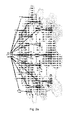
- Fig. 4
- shows how data are shared between the base stations after the entire MAC layer processing, which can be left decentralized, accordingly;
- Fig. 5
- shows an exemplary implementation of shared data exhange using Ethernet at cooperative base stations;
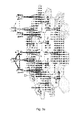
- Fig. 6
- shows CSI feedback and multiplexing with the shared data flow on the X2 interface; and
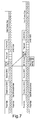
- Fig. 7
- shows how VLAN tags are used to identify the cooperation cluster and to organize the data flows.
- The invention will now be described in more detail. Again, according to the invention, three types of data streams are to be considered:
- Feeder link data for the terminal
- Shared data signals
- CSI coming from the terminals
- The invention's general approach is that all these streams are organized using the classical Ethernet protocol so that low-cost networking equipment can be used for the backhaul.
- Feeder data are intended for the mobile terminal served by the base station. In Long Term Evolution, LTE, the feeder data are organized in IP packets and transmitted over the S1 interface. Normally, such traffic is transported over Ethernet anyway.
- As indicated in
Fig. 3c , data are transmitted in a first hop over S1 from the aGW to the serving eNB. Data are then packed into transport blocks, encoded and mapped onto the radio bearer, RB. After the MAC layer we copy these already mapped and encoded data and forward the copy in a second hop over X2 to all base stations involved in the CoMP transmission. - Compared to the centralized approach, the invention has the advantage that data bits, and not IQ samples, are exchanged between the base stations. The load in the backhaul is significantly reduced in this way. Moreover, it is easier to synchronize the data at all BS at this stage in the transmission chain where all network and MAC layer processing is already completed. Thus, retransmissions are also controlled locally and need no additional coordination between the BS. Given that the X2 interface does not introduce to much latency, the delay due to data exchange is easily compensated using buffers at the precoder inputs.
- Since these shared data are already encoded, the maximum data rate on the X2 interface is given by the inverse of the code rate η times the peak rate in the system. For an exemplary 2x2 CoMP implementation with two base stations, this gives 2.150 = 300 Mbit/s. Consider a large network when K base stations in a cluster perform coherent downlink CoMP. X2 is a logical interface and it is assumed here that it will be physically realized over the feeder link at each base station. Hence, the X2 traffic is added to the own S1 data coming over the feeder link as well. In such a setup, a simple equation can be derived for the backhaul required by the distributed CoMP approach. It is given as

- Note that the backhaul scales superlinearly with the cluster size K. The more base stations are in the cluster, the higher is the throughput.
- In order to organize such common use of physical Ethernet links for e.g. user data and shared data, the data exchange between the cooperative base stations is organized as Ethernet traffic as well. The practical signal flow in the base stations and their communication over the X2 interface are shown in
Fig. 5 . - Summarizing the invention's synchroneous data exchange, first it reduces the backhaul load significantly. Second, it tolerates delays up to milliseconds which may occur in the real-world backhaul. Third, the data exchange is easily organized over standard Ethernet, which makes the multiplexing with the CSI very easy (see below).
- The third stream is the multi-cell channel state information, CSI, fed back from each terminal to the serving base. The provision of feedback causes a significant overhead and several techniques are suited to minimize the feedback overhead. Firstly, one may provide frequency-domain feedback only for those RBs likely to be assigned to a user. This divides the amount of feedback provided by each terminal by the number of terminals in a cell, in case of a fully loaded cell.
- A second alternative is to feedback the channel in the delay domain, instead of in the frequency domain. I.e. one would in principle Fourier-transform the channel, estimate the most relevant taps and feed back to the BS a list of the complex tap amplitudes and their delays.
- A combination of both methods might be useful as well. Let us assign a certain frequency subband to a terminal, within which cooperative transmission is potentially used. Ideally, this subband is a contiguous aggregation of sub-carriers. Inside this subband having a reduced bandwidth and therefore also a reduced temporal resolution, the terminal estimates the most relevant taps and their delays and sends them back to the base station.
- Next one may exploit correlation in time- and frequency domains. At low mobility and in a channel with limited multipath, correlation is very likely. In a scenario where demanding users are not likely to be mobile, the feedback rate can be reduced significantly. However, there is an inevitable up-link delay in the order of 5 ms for LTE. Moreover, the distribution of the CSI over the network and the computation of the precoder weights takes additional time. The overall delay calls for the use of prediction techniques.
- The invention propose to send such feedback as Ethernet packets over the air, in parallel to the uplink user data. These packets are formed so that a terminal always packs the entire multi-cell channel matrix in a given sub-band in one packet with or without prior compression. Such packets are fed out of the receiver signal processing chain using a dedicated Ethernet port marked as "CSI" at the terminal.
- Using Ethernet packets increases the implementation effort at first sight but it enables many new opportunities for the organization of the mobile network. First, it becomes very easy to record the CSI on standard computers, i.e. the invention provides a powerful measurement interface which may even be used at the application layer, e.g. to switch the transmission quality of a video stream depending on the instantanous channel state.
- Second, the invention enables a simple and powerful method to organize the feeder data, CSI and shared data flows in the backhaul of the cooperative base station system. The concept can be extended to more than two base stations and subgroups of base stations can be selected in a very flexible manner for the purpose of cooperative transmission. Furthermore it is ensured that not more data are passed through the network than actually needed.
- The signaling network is shown in
Fig. 6 for two cooperative base stations. It relies on widely available low-cost equipment for the IEEE802.3 Ethernet standard. Furthermore, the invention takes profit of an existing standard extension, namely the so-called Virtual Local Area Networks, VLANs, described in IEEE 802.1q. VLANs are based on a packet-switching technique which requires the use of an additional VLAN tag field in each packet (seeFig. 7 ). - The additional VLAN tag field has the following format:
-
- Tag Protocol Identifier (TPID): a 16-bit field set to a value of 0x8100 in order to identify the frame as an IEEE 802.1Q-tagged frame. This field is located at the same position as the EtherType/Size field in untagged frames, and is used to distinguish the frame from untagged frames.
- Priority Code Point (PCP): a 3-bit field which refers to the IEEE 802.1p priority. It indicates the frame priority level from 0 (lowest) to 7 (highest), which can be used to prioritize different classes of traffic (voice, video, data, etc).
- Canonical Format Indicator (CFI): a 1-bit field. If the value of this field is 1, the MAC address is in non-canonical format. If the value is 0, the MAC address is in canonical format. It is always set to zero for Ethernet switches. CFI is used for compatibility between Ethernet and Token Ring networks.
- VLAN Identifier (VID): a 12-bit field specifying the VLAN to which the frame belongs. A value of 0 means that the frame does not belong to any VLAN; in this case the 802.1Q tag specifies only a priority and is referred to as a priority tag. The hexadecimal value of 0xFFF is reserved. All other values may be used as VLAN identifiers, allowing up to 4094 VLANs.
- VLAN-enabled Ethernet switches can be configured so that a packet at a given input is switched to a certain output port depending on the VID. In a given switch, up to 4094 different input-output switching tables can be predefined.
- In the CoMP network, this VLAN functionality can be used very efficiently to multiplex and demultiplex the different types of traffic: CSI feedback in uplink direction, exchange of data between cooperative BS and application data of the MT (see
Fig. 6 ). The CSI is packed into a standard Ethernet packet using a multicast address. Packets denoted as C1 inFig. 6 are created by the physical layer processing and sent toport 2 of the MT over Ethernet. Next there is a switch adding the VLAN tag to the C1 packets identifying them as CSI feedback to be distributed in a specific set of cooperative base stations. Identification of both the cluster and the traffic type is encoded in the VID. - VLAN switches in the network are preconfigured eventually by the mobility management entity (MME) in the SAE network or any other entity organizing the flow of any data stream in the CoMP network. This entity knows the physical network topology. It derives the routes in the network over which the messages flow optimally to support the CoMP transmission. In each Ethernet switch, the packet switching rules for all possible cluster configurations are preconfigured using fixed switching tables depending on the VIDs. For organizing the traffic flow, the serving base station has to inform the terminal over the downlink control channel which VID address is used in the CSI packets identifying the assigned cooperation cluster.
- Both signals, i.e. the assignment of the VID and the corresponding VLAN tags in the CSI packets fed back over the uplink are transmitted over the air. Thus they are detectable, and thus the use of the proposed method can be proven.
- By using an accompanied VID, IP application data (denoted as D) for the terminal served by the base staion are identified at input 5 (see
Fig. 6 ). In the VLAN switch, the CSI is multiplexed with data onoutput 1.Port 1 at the MT can be regarded as a transparent Ethernet tunnel to the serving BS over the wireless link. - At the BS, the multiplexed up-link traffic is fed again into a VLAN switch. Based on the VIDs, the switch splits CSI and data packets and forwards them into different ports. The CSI stream C1 is copied into several output ports: The input of the precoder at BS1 (2), a mirror of
port 2 used for monitoring and measurements (4) and the inter-BS link (6) denoted as X2 interface in the LTE/SAE standardization. In addition to the C1 stream, a shared data stream SD1 containing the already encoded and scheduled downlink data for MT1 is also forwarded toport 6 of the switch. The switch at BS2 inFig. 6 performs equivalent packet switching. As a result, the data streams C2 and SD2 arrive onport 6 of the switch and they forwarded toport - In summary, the invention enables the efficient organization of user data, CSI feedback and shared data flows in the network behind a mobile radio system using cooperative base stations. The method is based on existing network protocols and allows the use of cheap off-the-shelf equipment. The assignment of the VLAN identifier (VID) over the downlink control channel and the use of it for the CSI feedback over the uplink are both clearly detectable. One may frequently find other terminals transmitting their feedback in other cells using the same VIDs. This proofs the use of VIDs for the purpose of coordinated multipoint (CoMP) transmission.
- While the invention has been illustrated and described in detail in the drawings and foregoing description, such illustration and description are to be considered illustrative or exemplary and not restrictive. It will be understood that changes and modifications may be made by those of ordinary skill within the scope of the following claims. In particular, the present invention covers further embodiments with any combination of features from different embodiments described above and below.
- Furthermore, in the claims the word "comprising" does not exclude other elements or steps, and the indefinite article "a" or "an" does not exclude a plurality. A single unit may fulfil the functions of several features recited in the claims. The terms "essentially", "about", "approximately" and the like in connection with an attribute or a value particularly also define exactly the attribute or exactly the value, respectively. Any reference signs in the claims should not be construed as limiting the scope.
-
- [1] J. Winters, Optimum combining in digital mobile radio with cochannel interference, IEEE Transactions on Vehicular Technology, Vol. 33, No. 3, pp. 144-155, Aug 1984.
- [2] P. Baier, M. Meurer, T. Weber, and H. Troger, "Joint transmission (JT), an alternative rationale for the downlink of time division CDMA using multi-element transmit antennas," Proc. IEEE ISSSTA '00, 2000.
- [3] S. Shamai and B. Zaidel, "Enhancing the cellular downlink capacity via co-processing at the transmitting end," Proc. IEEE VTC '01 Spring, vol. 3, pp. 1745-1749, 2001.
- [4] T. Weber, I. Maniatis, A. Sklavos, Y. Liu, E. Costa, H. Haas, and E. Schulz, "Joint transmission and detection integrated network (JOINT), a generic proposal for beyond 3G systems," Proc. ICT'02, vol. 3, pp. 479-483, 2002.
- [5] A. Goldsmith, S. Jafar, N. Jindal, and S. Vishwanath, "Capacity limits of MIMO channels," IEEE J. Sel. Areas Commun., vol. 21, no. 5, pp. 684-702, June 2003.
- [6] H. Huang and S. Venkatesan, "Asymptotic downlink capacity of coordinated cellular networks," Proc. ACSSC '04, vol. 1, pp. 850-855, 2004.
- [7] L. Thiele, V. Jungnickel, "Adaptive MIMO transmission in a realistic multicell scenario," Proc. IEEE Radio and Wireless Symposium, 2008, pp.531-534, Jan. 2008.
- [8] V. Jungnickel, M. Schellmann, L. Thiele, T. Wirth, T. Haustein, O. Koch, E. Zirwas, and E. Schulz, "Interference aware scheduling in the multiuser MIMO-OFDM downlink," IEEE Commun. Mag., vol. 47, pp. 56-66, 2009.
- [9] H. Olofsson, J. Naslund, J. Skold, "Interference diversity gain in frequency hopping GSM," in Proc. IEEE 45th Vehicular Technology Conference 1995, Vol. 1, pp. 102-106.
- [10] L. Thiele, M. Schellmann, W. Zirwas, and V. Jungnickel, Capacity Scaling of Multiuser MIMO with Limited Feedback in a Multicell Environment, 41 st Asilomar Conference on Signals, Systems and Computers, Monterey, USA, IEEE, Nov. 2007, invited
- [11] M. H. M. Costa, "Writing on dirty paper," IEEE Trans. Inf. Theory, vol. IT-29, No. 3, pp. 439-441, May 1983.
- [12] W. Zirwas, J. H. Kim, V. Jungnickel, M. Schubert, T. Weber, A. Ahrens, and M. Haardt, Distributed Antenna Systems. Auerbach, 2007, ch. 10, Distributed Organization of Cooperative Antenna Systems, pp. 279-311.
- [13] V. Jungnickel, L. Thiele, M. Schellmann, T. Wirth, W. Zirwas, T. Haustein, and E. Schulz, "Implementation concepts for distributed cooperative transmission," Proc. ACSSC '08, oct 2008.
- [14] W. Zirwas, W. Mennerich, M. Schubert, L. Thiele, V. Jungnickel, and E. Schulz, Cooperative Transmission Schemes. CRC Press, Taylor and Francis Group, 2009.
- [15] 3GPP TS 36.300 v8.2.0, "Technical specification group radio access network; evolved universal terrestrial radio access (e-utra) and evolved universal terrestrial radio access network (e-utran); overall description; .
Claims (25)
- Mobile communication method in a network using coordinated multipoint, CoMP, transmission, the network comprising at least one base station serving a plurality of mobile terminals, the method being characterized in that each network data and signaling packet to be exchanged within the cooperation cluster is tagged with an additional identifier defining the set of base stations in the cluster.
- The method of claim 1, wherein the network data packets are Ethernet data packets, and wherein each Ethernet data packet is tagged with a Virtual Local Area Networks, VLAN, group number (VLAN identifier, VID).
- The method of claim 1, wherein the network protocol is Ethernet protocol or multicast IP protocol or any other group networking protocol and the identifiers are VLAN tags, IP multicast addresses or any other identifier for the networking group, respectively, being assigned over a wireless downlink control channel to the terminals and used within the group for organizing the data flows.
- The method of any of the preceding claims, wherein
feeder link data for each mobile terminal are transmitted using a network protocol; shared data between base stations involved in the CoMP transmission is exchanged using the same network protocol; and
downlink channel state information, CSI, measured by each mobile terminal is transmitted to the serving base station using the same network protocol. - The method of claim 4, wherein the network protocol is Ethernet or IP multicasting.
- Mobile communication method in a network using coordinated multipoint, CoMP, transmission, the network comprising at least one base station serving a plurality of mobile terminals, the method being characterized in that
feeder link data for each mobile terminal are transmitted using a network protocol; shared data between base stations involved in the CoMP transmission is exchanged using the same network protocol; and
downlink channel state information, CSI, measured by each mobile terminal is transmitted to the serving base station using the same network protocol. - The method of any of claims 4 to 6, wherein the data flow for a given terminal over the S1 link from the advanced gateway, aGW, is terminated at the serving master base station enhanced NodeB, eNB, and, data are then packed into transport blocks, encoded and mapped onto the radio bearer, RB, and after the MAC layer, the already mapped and encoded data are copied and the copy is forwarded over the X2 interface to all base stations involved in the CoMP transmission.
- The method of any of claims 4 to 7, wherein the channel state information, CSI, fed back from each terminal to the serving base is provided as frequency-domain feedback only for those RBs likely to be assigned to a user.
- The method of any of claims 4 to 8, wherein the channel state information, CSI, fed back from each terminal to the serving base, is provided in the delay domain.
- The method of any of claims 4 to 9, wherein the channel state information, CSI, fed back from each terminal to the serving base using preferably Ethernet or IP protocol, is transmitted in parallel to the uplink user data.
- The method of claim 10, wherein the packets are formed so that a terminal always packs the entire multi-cell channel matrix in a given sub-band in one packet.
- The method of any of claims 6 to 11, each network data packet is tagged with an additional identifier.
- The method of claim 12, wherein each Ethernet data packet is tagged with a Virtual Local Area Networks, VLAN, group number.
- The method of claim 12, wherein each IP data packet contains a multicast address as a group number.
- The method of claim 13, wherein the VLAN group number is located in the packet at the position being used, in untagged frames, by the EtherType/Size field.
- Mobile communication system in a network using coordinated multipoint, CoMP, transmission, the network comprising at least one base station serving a plurality of mobile terminals, the system being characterized in that each network data and signaling packet to be exchanged within the cooperation cluster is tagged with an additional identifier defining the set of base stations in the cluster.
- The system of claim 16, wherein the network data packets are Ethernet data packets, and wherein each Ethernet data packet is tagged with a Virtual Local Area Networks, VLAN, group number.
- Mobile communication system in a network using coordinated multipoint, CoMP, transmission, the network comprising at least one base station serving a plurality of mobile terminals, the system being characterized in that
feeder link data for each mobile terminal are transmitted using a network protocol; the bases stations involved in the CoMP transmission are adapted to exchange shared data between themselves using the same network protocol; and
each mobile terminal is adapted to transmit measured downlink channel state information, CSI, to the serving base station using the same network protocol. - The system of claim 18, wherein each network data packet is tagged with an additional identifier.
- The system of claim 19, wherein the network protocol is the Ethernet protocol, and wherein each Ethernet data packet is tagged with a Virtual Local Area Networks, VLAN, group number.
- The system of claim 19, wherein the network protocol is the Internet protocol, and wherein the IP packet has a multicast address.
- Base station in a mobile communication system in a network using coordinated multipoint, CoMP, transmission, the network comprising at least one base station serving a plurality of mobile terminals, the base station being characterized in that
it is adapted to receive feeder link data for each mobile terminal using Ethernet protocol;
it is adapted to exchange shared data with other base stations using Ethernet protocol;
and
it is adapted to receive from each mobile terminal it serves measured downlink channel state information, CSI, using Ethernet protocol. - Base station in a mobile communication system in a network using coordinated multipoint, CoMP, transmission, the network comprising at least one base station serving a plurality of mobile terminals, the base station being characterized in that
it is adapted to receive feeder link data for each mobile terminal using IP protocol;
it is adapted to exchange shared data with other base stations using IP protocol; and
it is adapted to receive from each mobile terminal it serves measured downlink channel state information, CSI, using IP protocol. - The mobile communication system of claim 17 or 20, or the base station of claim 22, wherein the base station comprises a VLAN-enabled Ethernet switch capable of doing packet-switching depending on the VLAN identifier..
- The mobile communication system of claim 17 or 20, or the base station of claim 23, wherein the base station comprises a multicast-enabled IP router capable of doing IP packet switching based on the multi-cast address.
Priority Applications (4)
| Application Number | Priority Date | Filing Date | Title |
|---|---|---|---|
| EP10178477.5A EP2434835B1 (en) | 2010-09-22 | 2010-09-22 | Coordinated multi-point transmission COMP data and signalling on X2-interface using additional VLAN identifier |
| ES10178477T ES2426401T3 (en) | 2010-09-22 | 2010-09-22 | Data and coordinated multipoint transmission signaling, CoMP on the X2 interface using an additional VLAN identifier |
| PL10178477T PL2434835T3 (en) | 2010-09-22 | 2010-09-22 | Coordinated multi-point transmission COMP data and signalling on X2-interface using additional VLAN identifier |
| HRP20130693AT HRP20130693T1 (en) | 2010-09-22 | 2013-07-23 | Coordinated multi-point transmission comp data and signalling on x2-interface using additional vlan identifier |
Applications Claiming Priority (1)
| Application Number | Priority Date | Filing Date | Title |
|---|---|---|---|
| EP10178477.5A EP2434835B1 (en) | 2010-09-22 | 2010-09-22 | Coordinated multi-point transmission COMP data and signalling on X2-interface using additional VLAN identifier |
Publications (2)
| Publication Number | Publication Date |
|---|---|
| EP2434835A1 true EP2434835A1 (en) | 2012-03-28 |
| EP2434835B1 EP2434835B1 (en) | 2013-07-10 |
Family
ID=43598118
Family Applications (1)
| Application Number | Title | Priority Date | Filing Date |
|---|---|---|---|
| EP10178477.5A Active EP2434835B1 (en) | 2010-09-22 | 2010-09-22 | Coordinated multi-point transmission COMP data and signalling on X2-interface using additional VLAN identifier |
Country Status (4)
| Country | Link |
|---|---|
| EP (1) | EP2434835B1 (en) |
| ES (1) | ES2426401T3 (en) |
| HR (1) | HRP20130693T1 (en) |
| PL (1) | PL2434835T3 (en) |
Cited By (9)
| Publication number | Priority date | Publication date | Assignee | Title |
|---|---|---|---|---|
| WO2013136043A1 (en) * | 2012-03-13 | 2013-09-19 | Airspan Networks Inc. | Cooperative components in a wireless feeder network |
| CN105450560A (en) * | 2014-08-14 | 2016-03-30 | 华为技术有限公司 | Method for channel feedback transmission |
| WO2017081207A1 (en) | 2015-11-10 | 2017-05-18 | Fraunhofer-Gesellschaft zur Förderung der angewandten Forschung e.V. | System and method for providing a wireless communication with a mobile device |
| EP3107326A4 (en) * | 2014-02-14 | 2017-08-09 | Nec Corporation | Network control device, communication device, control method, communication method, and program |
| EP3277037A1 (en) * | 2016-07-29 | 2018-01-31 | Deutsche Telekom AG | Communication system for communicating in a communication network |
| EP2636159B1 (en) * | 2010-11-05 | 2018-06-20 | Telefonaktiebolaget LM Ericsson (publ) | Comp operation in cellular communication networks |
| WO2018136180A1 (en) * | 2017-01-17 | 2018-07-26 | Qualcomm Incorporated | Methods and systems for simultaneous multi access point transmissions on a wireless channel |
| CN109194763A (en) * | 2018-09-21 | 2019-01-11 | 北京邮电大学 | Caching method based on small base station self-organizing cooperative in a kind of super-intensive network |
| US10356735B2 (en) | 2013-03-07 | 2019-07-16 | Hewlett Packard Enterprise Development Lp | Synchronizing signal transmissions by antenna apparatuses |
-
2010
- 2010-09-22 EP EP10178477.5A patent/EP2434835B1/en active Active
- 2010-09-22 PL PL10178477T patent/PL2434835T3/en unknown
- 2010-09-22 ES ES10178477T patent/ES2426401T3/en active Active
-
2013
- 2013-07-23 HR HRP20130693AT patent/HRP20130693T1/en unknown
Non-Patent Citations (20)
| Title |
|---|
| "Technical specification group radio access network; evolved universal terrestrial radio access (e-utra) and evolved universal terrestrial radio access network (e-utran); overall description; stage 2", TECH. REP., 2007, pages 9 |
| A. GOLDSMITH; S. JAFAR; N. JINDAL; S. VISHWANATH: "Capacity limits of MIMO channels", IEEE J. SEL. AREAS COMMUN., vol. 21, no. 5, June 2003 (2003-06-01), pages 684 - 702 |
| ALCATEL-LUCENT: "Consideration of Backhaul Technology Evolution in Support of CoMP", 3GPP DRAFT; R1-093344, 3RD GENERATION PARTNERSHIP PROJECT (3GPP), MOBILE COMPETENCE CENTRE ; 650, ROUTE DES LUCIOLES ; F-06921 SOPHIA-ANTIPOLIS CEDEX ; FRANCE, no. Shenzhen, China; 20090824, 24 August 2009 (2009-08-24), XP050388124 * |
| FOULI K ET AL: "The road to carrier-grade ethernet -[Topics in optical communications]", IEEE COMMUNICATIONS MAGAZINE, IEEE SERVICE CENTER, PISCATAWAY, US, vol. 47, no. 3, 1 March 2009 (2009-03-01), pages S30 - S38, XP011254107, ISSN: 0163-6804 * |
| H. HUANG; S. VENKATESAN: "Asymptotic downlink capacity of coordinated cellular networks", PROC. ACSSC '04, vol. 1, 2004, pages 850 - 855 |
| H. OLOFSSON; J. NASLUND; J. SKOLD: "Interference diversity gain in frequency hopping GSM", PROC. IEEE 45TH VEHICULAR TECHNOLOGY CONFERENCE, vol. 1, 1995, pages 102 - 106 |
| J. WINTERS: "Optimum combining in digital mobile radio with cochannel interference", IEEE TRANSACTIONS ON VEHICULAR TECHNOLOGY, vol. 33, no. 3, August 1984 (1984-08-01), pages 144 - 155 |
| JUNGNICKEL V ET AL: "Coordinated Multipoint Trials in the Downlink", GLOBECOM WORKSHOPS, 2009 IEEE, IEEE, PISCATAWAY, NJ, USA, 30 November 2009 (2009-11-30), pages 1 - 7, XP031585744, ISBN: 978-1-4244-5626-0 * |
| L. THIELE; M. SCHELLMANN; W. ZIRWAS; V. JUNGNICKEL: "Capacity Scaling of Multiuser MIMO with Limited Feedback in a Multicell Environment", 41ST ASILOMAR CONFERENCE ON SIGNALS, SYSTEMS AND COMPUTERS, November 2007 (2007-11-01) |
| L. THIELE; V. JUNGNICKEL: "Adaptive MIMO transmission in a realistic multicell scenario", PROC. IEEE RADIO AND WIRELESS SYMPOSIUM, vol. 2008, January 2008 (2008-01-01), pages 531 - 534 |
| M. H. M. COSTA: "Writing on dirty paper", IEEE TRANS. INF. THEORY, vol. IT-29, no. 3, May 1983 (1983-05-01), pages 439 - 441 |
| P. BAIER; M. MEURER; T. WEBER; H. TROGER: "Joint transmission (JT), an alternative rationale for the downlink of time division CDMA using multi-element transmit antennas", PROC. IEEE ISSSTA '00, 2000 |
| S. SHAMAI; B. ZAIDEL: "Enhancing the cellular downlink capacity via co-processing at the transmitting end", PROC. IEEE VTC '01 SPRING, vol. 3, 2001, pages 1745 - 1749 |
| SANCHEZ R ET AL: "Ethernet as a carrier grade technology: developments and innovations", IEEE COMMUNICATIONS MAGAZINE, IEEE SERVICE CENTER, PISCATAWAY, US, vol. 46, no. 9, 1 September 2008 (2008-09-01), pages 88 - 94, XP011234293, ISSN: 0163-6804, DOI: 10.1109/MCOM.2008.4623712 * |
| T. WEBER; 1. MANIATIS; A. SKLAVOS; Y. LIU; E. COSTA; H. HAAS; E. SCHULZ: "Joint transmission and detection integrated network (JOINT), a generic proposal for beyond 3G systems", PROC. ICT'02, vol. 3, 2002, pages 479 - 483 |
| V. JUNGNICKEL, A. FORCK, S. JAECKEL, F. BAUERMEISTER, S. SCHIFFERMUELLER, S. SCHUBERT, S. WAHLS, L. THIELE, T. HAUSTEIN, W. KREHER: "Field Trials using Coordinated Multi-PointTransmission in the Downlink", 3 October 2011 (2011-10-03), pages 1 - 6, XP002624923, Retrieved from the Internet <URL:http://www.mk.tu-berlin.de/publikationen/objects/2010/publikation.2010-10-03.2608149548/datei> [retrieved on 20110224] * |
| V. JUNGNICKEL; L. THIELE; M. SCHELLMANN; T. WIRTH; W. ZIRWAS; T. HAUSTEIN; E. SCHULZ: "Implementation concepts for distributed cooperative transmission", PROC. ACSSC, 8 October 2008 (2008-10-08) |
| V. JUNGNICKEL; M. SCHELLMANN; L. THIELE; T. WIRTH; T. HAUSTEIN; O. KOCH; E. ZIRWAS; E. SCHULZ: "Interference aware scheduling in the multiuser MIMO-OFDM downlink", IEEE COMMUN. MAG., vol. 47, 2009, pages 56 - 66 |
| W. ZIRWAS; J. H. KIM; V. JUNGNICKEL; M. SCHUBERT; T. WEBER; A. AHRENS; M. HAARDT: "Distributed Organization of Cooperative Antenna Systems", 2007, article "Distributed Antenna Systems", pages: 279 - 311 |
| W. ZIRWAS; W. MENNERICH; M. SCHUBERT; L. THIELE; V. JUNGNICKEL; E. SCHULZ: "Cooperative Transmission Schemes", 2009, CRC PRESS, TAYLOR AND FRANCIS GROUP |
Cited By (16)
| Publication number | Priority date | Publication date | Assignee | Title |
|---|---|---|---|---|
| EP2636159B1 (en) * | 2010-11-05 | 2018-06-20 | Telefonaktiebolaget LM Ericsson (publ) | Comp operation in cellular communication networks |
| US9560676B2 (en) | 2012-03-13 | 2017-01-31 | Airspan Networks Inc. | Cooperative components in a wireless feeder network |
| WO2013136043A1 (en) * | 2012-03-13 | 2013-09-19 | Airspan Networks Inc. | Cooperative components in a wireless feeder network |
| US10356735B2 (en) | 2013-03-07 | 2019-07-16 | Hewlett Packard Enterprise Development Lp | Synchronizing signal transmissions by antenna apparatuses |
| EP3107326A4 (en) * | 2014-02-14 | 2017-08-09 | Nec Corporation | Network control device, communication device, control method, communication method, and program |
| EP3145139A4 (en) * | 2014-08-14 | 2017-08-02 | Huawei Technologies Co. Ltd. | Method for transmitting channel feedback |
| CN105450560B (en) * | 2014-08-14 | 2019-02-12 | 华为技术有限公司 | A method for channel feedback transmission |
| CN105450560A (en) * | 2014-08-14 | 2016-03-30 | 华为技术有限公司 | Method for channel feedback transmission |
| US10506565B2 (en) | 2014-08-14 | 2019-12-10 | Huawei Technologies Co., Ltd. | Channel feedback information transmission method and apparatus |
| US11160063B2 (en) | 2014-08-14 | 2021-10-26 | Huawei Technologies Co., Ltd. | Channel feedback information transmission method and apparatus |
| WO2017081207A1 (en) | 2015-11-10 | 2017-05-18 | Fraunhofer-Gesellschaft zur Förderung der angewandten Forschung e.V. | System and method for providing a wireless communication with a mobile device |
| US10326524B2 (en) | 2015-11-10 | 2019-06-18 | Fraunhofer-Gesellschaft Zur Foerderung Der Angewandten Forschung E.V. | System and method for providing a wireless communication with a mobile device |
| EP3277037A1 (en) * | 2016-07-29 | 2018-01-31 | Deutsche Telekom AG | Communication system for communicating in a communication network |
| WO2018019993A1 (en) * | 2016-07-29 | 2018-02-01 | Deutsche Telekom Ag | Communications system for communication in a communications network |
| WO2018136180A1 (en) * | 2017-01-17 | 2018-07-26 | Qualcomm Incorporated | Methods and systems for simultaneous multi access point transmissions on a wireless channel |
| CN109194763A (en) * | 2018-09-21 | 2019-01-11 | 北京邮电大学 | Caching method based on small base station self-organizing cooperative in a kind of super-intensive network |
Also Published As
| Publication number | Publication date |
|---|---|
| PL2434835T3 (en) | 2013-11-29 |
| EP2434835B1 (en) | 2013-07-10 |
| HRP20130693T1 (en) | 2013-10-11 |
| ES2426401T3 (en) | 2013-10-23 |
Similar Documents
| Publication | Publication Date | Title |
|---|---|---|
| EP2434835B1 (en) | Coordinated multi-point transmission COMP data and signalling on X2-interface using additional VLAN identifier | |
| Gomes et al. | Fronthaul evolution: from CPRI to Ethernet | |
| Jungnickel et al. | Coordinated multipoint trials in the downlink | |
| Irmer et al. | Coordinated multipoint: Concepts, performance, and field trial results | |
| JP2024023451A (en) | Utilization of inter-cell multiplexing gain in wireless cellular systems | |
| CN103190085B (en) | Enhanced base station and method for communicating over an enhanced distributed antenna system (eDAS) | |
| CN102239659B (en) | Method and communication network element for transmitting reference signals | |
| Liu et al. | Redesigning fronthaul for next-generation networks: beyond baseband samples and point-to-point links | |
| US8494077B2 (en) | Method and communication system for transmitting data in a multiple-input multiple-output (MIMO) system | |
| Jungnickel et al. | Field trials using coordinated multi-point transmission in the downlink | |
| CN114828252B (en) | Method and apparatus for multi-point data transmission | |
| CN109565364A (en) | Signal processing in spatial multiplexing MIMO communication | |
| GB2479658A (en) | Compensating for propagation delays in coordinated multi-point transmission | |
| Jungnickel et al. | Implementation concepts for distributed cooperative transmission | |
| EP3444976B1 (en) | Wireless communication system, central station apparatus, distributed station apparatus, communication method of central station apparatus, and communication method of distributed station apparatus | |
| KR20230066275A (en) | Multi-antenna based precoding method and apparatus in wireless communication system | |
| EP4500715A1 (en) | Channel state information (csi) measurement and reporting for scalable multiple-input multiple-output (mimo) communication on a downlink | |
| Manolakis et al. | Impairment modeling for joint transmission CoMP | |
| Ibing et al. | Joint transmission and detection in hexagonal grid for 3GPP LTE | |
| WO2024168461A1 (en) | Methods for performing simultaneous measurements within a synchronization signal block (ssb) measurement timing configuration (smtc) window | |
| WO2024168460A1 (en) | Methods for reducing beam sweeping time for a user equipment | |
| JP6064017B2 (en) | Method and communication network element for transmitting a reference signal | |
| Haustein | Field trials using coordinated multi-point transmission in the downlink | |
| Somalaxmi et al. | PERFORMANCE ANALYSIS OF MU-MIMO ANTENNA WITH CARRIER AGGREGATION RESOURCE ALLOCATION TECHNIQUE IN LTE-A NETWORK | |
| Pleshkova et al. | Development of a Simulation Model of Multiband Radio Transmission Network for Access to Audio Information in Open RAN |
Legal Events
| Date | Code | Title | Description |
|---|---|---|---|
| PUAI | Public reference made under article 153(3) epc to a published international application that has entered the european phase |
Free format text: ORIGINAL CODE: 0009012 |
|
| 17P | Request for examination filed |
Effective date: 20110727 |
|
| AK | Designated contracting states |
Kind code of ref document: A1 Designated state(s): AL AT BE BG CH CY CZ DE DK EE ES FI FR GB GR HR HU IE IS IT LI LT LU LV MC MK MT NL NO PL PT RO SE SI SK SM TR |
|
| AX | Request for extension of the european patent |
Extension state: BA ME RS |
|
| RIC1 | Information provided on ipc code assigned before grant |
Ipc: H04W 72/04 20090101ALN20121109BHEP Ipc: H04L 12/46 20060101ALI20121109BHEP Ipc: H04B 7/02 20060101ALI20121109BHEP Ipc: H04W 92/20 20090101AFI20121109BHEP Ipc: H04W 8/26 20090101ALN20121109BHEP Ipc: H04W 88/08 20090101ALN20121109BHEP |
|
| RIC1 | Information provided on ipc code assigned before grant |
Ipc: H04B 7/02 20060101ALI20121129BHEP Ipc: H04L 12/46 20060101ALI20121129BHEP Ipc: H04W 8/26 20090101ALN20121129BHEP Ipc: H04W 72/04 20090101ALN20121129BHEP Ipc: H04W 92/20 20090101AFI20121129BHEP Ipc: H04W 88/08 20090101ALN20121129BHEP |
|
| GRAP | Despatch of communication of intention to grant a patent |
Free format text: ORIGINAL CODE: EPIDOSNIGR1 |
|
| GRAS | Grant fee paid |
Free format text: ORIGINAL CODE: EPIDOSNIGR3 |
|
| GRAA | (expected) grant |
Free format text: ORIGINAL CODE: 0009210 |
|
| RIN1 | Information on inventor provided before grant (corrected) |
Inventor name: JUNGNICKEL. DR. VOLKER Inventor name: BAUERMEISTER, FRANK Inventor name: HAUSTEIN, DR. THOMAS Inventor name: FORCK, FRANK Inventor name: MUELLER, JUERGEN Inventor name: JAECKEL, STEPHAN Inventor name: KREHER, WOLFGANG |
|
| AK | Designated contracting states |
Kind code of ref document: B1 Designated state(s): AL AT BE BG CH CY CZ DE DK EE ES FI FR GB GR HR HU IE IS IT LI LT LU LV MC MK MT NL NO PL PT RO SE SI SK SM TR |
|
| REG | Reference to a national code |
Ref country code: GB Ref legal event code: FG4D |
|
| REG | Reference to a national code |
Ref country code: CH Ref legal event code: EP Ref country code: AT Ref legal event code: REF Ref document number: 621565 Country of ref document: AT Kind code of ref document: T Effective date: 20130715 |
|
| REG | Reference to a national code |
Ref country code: HR Ref legal event code: TUEP Ref document number: P20130693 Country of ref document: HR |
|
| REG | Reference to a national code |
Ref country code: RO Ref legal event code: EPE |
|
| REG | Reference to a national code |
Ref country code: IE Ref legal event code: FG4D |
|
| REG | Reference to a national code |
Ref country code: DE Ref legal event code: R096 Ref document number: 602010008368 Country of ref document: DE Effective date: 20130905 |
|
| REG | Reference to a national code |
Ref country code: HR Ref legal event code: T1PR Ref document number: P20130693 Country of ref document: HR |
|
| REG | Reference to a national code |
Ref country code: NL Ref legal event code: T3 |
|
| REG | Reference to a national code |
Ref country code: GR Ref legal event code: EP Ref document number: 20130401667 Country of ref document: GR Effective date: 20130920 |
|
| REG | Reference to a national code |
Ref country code: ES Ref legal event code: FG2A Ref document number: 2426401 Country of ref document: ES Kind code of ref document: T3 Effective date: 20131023 |
|
| PG25 | Lapsed in a contracting state [announced via postgrant information from national office to epo] |
Ref country code: SI Free format text: LAPSE BECAUSE OF FAILURE TO SUBMIT A TRANSLATION OF THE DESCRIPTION OR TO PAY THE FEE WITHIN THE PRESCRIBED TIME-LIMIT Effective date: 20130710 |
|
| REG | Reference to a national code |
Ref country code: PL Ref legal event code: T3 |
|
| REG | Reference to a national code |
Ref country code: SK Ref legal event code: T3 Ref document number: E 14953 Country of ref document: SK |
|
| REG | Reference to a national code |
Ref country code: LT Ref legal event code: MG4D |
|
| PG25 | Lapsed in a contracting state [announced via postgrant information from national office to epo] |
Ref country code: SE Free format text: LAPSE BECAUSE OF FAILURE TO SUBMIT A TRANSLATION OF THE DESCRIPTION OR TO PAY THE FEE WITHIN THE PRESCRIBED TIME-LIMIT Effective date: 20130710 Ref country code: NO Free format text: LAPSE BECAUSE OF FAILURE TO SUBMIT A TRANSLATION OF THE DESCRIPTION OR TO PAY THE FEE WITHIN THE PRESCRIBED TIME-LIMIT Effective date: 20131010 Ref country code: IS Free format text: LAPSE BECAUSE OF FAILURE TO SUBMIT A TRANSLATION OF THE DESCRIPTION OR TO PAY THE FEE WITHIN THE PRESCRIBED TIME-LIMIT Effective date: 20131110 Ref country code: CY Free format text: LAPSE BECAUSE OF FAILURE TO SUBMIT A TRANSLATION OF THE DESCRIPTION OR TO PAY THE FEE WITHIN THE PRESCRIBED TIME-LIMIT Effective date: 20130814 Ref country code: LT Free format text: LAPSE BECAUSE OF FAILURE TO SUBMIT A TRANSLATION OF THE DESCRIPTION OR TO PAY THE FEE WITHIN THE PRESCRIBED TIME-LIMIT Effective date: 20130710 Ref country code: PT Free format text: LAPSE BECAUSE OF FAILURE TO SUBMIT A TRANSLATION OF THE DESCRIPTION OR TO PAY THE FEE WITHIN THE PRESCRIBED TIME-LIMIT Effective date: 20131111 Ref country code: BE Free format text: LAPSE BECAUSE OF FAILURE TO SUBMIT A TRANSLATION OF THE DESCRIPTION OR TO PAY THE FEE WITHIN THE PRESCRIBED TIME-LIMIT Effective date: 20130710 |
|
| PG25 | Lapsed in a contracting state [announced via postgrant information from national office to epo] |
Ref country code: LV Free format text: LAPSE BECAUSE OF FAILURE TO SUBMIT A TRANSLATION OF THE DESCRIPTION OR TO PAY THE FEE WITHIN THE PRESCRIBED TIME-LIMIT Effective date: 20130710 Ref country code: FI Free format text: LAPSE BECAUSE OF FAILURE TO SUBMIT A TRANSLATION OF THE DESCRIPTION OR TO PAY THE FEE WITHIN THE PRESCRIBED TIME-LIMIT Effective date: 20130710 |
|
| PG25 | Lapsed in a contracting state [announced via postgrant information from national office to epo] |
Ref country code: CY Free format text: LAPSE BECAUSE OF FAILURE TO SUBMIT A TRANSLATION OF THE DESCRIPTION OR TO PAY THE FEE WITHIN THE PRESCRIBED TIME-LIMIT Effective date: 20130710 |
|
| PG25 | Lapsed in a contracting state [announced via postgrant information from national office to epo] |
Ref country code: MC Free format text: LAPSE BECAUSE OF FAILURE TO SUBMIT A TRANSLATION OF THE DESCRIPTION OR TO PAY THE FEE WITHIN THE PRESCRIBED TIME-LIMIT Effective date: 20130710 Ref country code: DK Free format text: LAPSE BECAUSE OF FAILURE TO SUBMIT A TRANSLATION OF THE DESCRIPTION OR TO PAY THE FEE WITHIN THE PRESCRIBED TIME-LIMIT Effective date: 20130710 Ref country code: EE Free format text: LAPSE BECAUSE OF FAILURE TO SUBMIT A TRANSLATION OF THE DESCRIPTION OR TO PAY THE FEE WITHIN THE PRESCRIBED TIME-LIMIT Effective date: 20130710 |
|
| PLBE | No opposition filed within time limit |
Free format text: ORIGINAL CODE: 0009261 |
|
| STAA | Information on the status of an ep patent application or granted ep patent |
Free format text: STATUS: NO OPPOSITION FILED WITHIN TIME LIMIT |
|
| 26N | No opposition filed |
Effective date: 20140411 |
|
| REG | Reference to a national code |
Ref country code: HU Ref legal event code: AG4A Ref document number: E019396 Country of ref document: HU |
|
| REG | Reference to a national code |
Ref country code: IE Ref legal event code: MM4A |
|
| REG | Reference to a national code |
Ref country code: DE Ref legal event code: R097 Ref document number: 602010008368 Country of ref document: DE Effective date: 20140411 |
|
| PG25 | Lapsed in a contracting state [announced via postgrant information from national office to epo] |
Ref country code: IE Free format text: LAPSE BECAUSE OF NON-PAYMENT OF DUE FEES Effective date: 20130922 |
|
| REG | Reference to a national code |
Ref country code: CH Ref legal event code: PL |
|
| PG25 | Lapsed in a contracting state [announced via postgrant information from national office to epo] |
Ref country code: SM Free format text: LAPSE BECAUSE OF FAILURE TO SUBMIT A TRANSLATION OF THE DESCRIPTION OR TO PAY THE FEE WITHIN THE PRESCRIBED TIME-LIMIT Effective date: 20130710 |
|
| PG25 | Lapsed in a contracting state [announced via postgrant information from national office to epo] |
Ref country code: MT Free format text: LAPSE BECAUSE OF FAILURE TO SUBMIT A TRANSLATION OF THE DESCRIPTION OR TO PAY THE FEE WITHIN THE PRESCRIBED TIME-LIMIT Effective date: 20130710 |
|
| PG25 | Lapsed in a contracting state [announced via postgrant information from national office to epo] |
Ref country code: CH Free format text: LAPSE BECAUSE OF NON-PAYMENT OF DUE FEES Effective date: 20140930 Ref country code: BG Free format text: LAPSE BECAUSE OF FAILURE TO SUBMIT A TRANSLATION OF THE DESCRIPTION OR TO PAY THE FEE WITHIN THE PRESCRIBED TIME-LIMIT Effective date: 20130710 Ref country code: LU Free format text: LAPSE BECAUSE OF NON-PAYMENT OF DUE FEES Effective date: 20130922 Ref country code: LI Free format text: LAPSE BECAUSE OF NON-PAYMENT OF DUE FEES Effective date: 20140930 Ref country code: MK Free format text: LAPSE BECAUSE OF FAILURE TO SUBMIT A TRANSLATION OF THE DESCRIPTION OR TO PAY THE FEE WITHIN THE PRESCRIBED TIME-LIMIT Effective date: 20130710 |
|
| REG | Reference to a national code |
Ref country code: FR Ref legal event code: PLFP Year of fee payment: 7 |
|
| REG | Reference to a national code |
Ref country code: FR Ref legal event code: PLFP Year of fee payment: 8 |
|
| REG | Reference to a national code |
Ref country code: FR Ref legal event code: PLFP Year of fee payment: 9 |
|
| PG25 | Lapsed in a contracting state [announced via postgrant information from national office to epo] |
Ref country code: AL Free format text: LAPSE BECAUSE OF FAILURE TO SUBMIT A TRANSLATION OF THE DESCRIPTION OR TO PAY THE FEE WITHIN THE PRESCRIBED TIME-LIMIT Effective date: 20130710 |
|
| REG | Reference to a national code |
Ref country code: HR Ref legal event code: ODRP Ref document number: P20130693 Country of ref document: HR Payment date: 20190917 Year of fee payment: 10 |
|
| REG | Reference to a national code |
Ref country code: HR Ref legal event code: ODRP Ref document number: P20130693 Country of ref document: HR Payment date: 20200909 Year of fee payment: 11 |
|
| REG | Reference to a national code |
Ref country code: HR Ref legal event code: ODRP Ref document number: P20130693 Country of ref document: HR Payment date: 20210917 Year of fee payment: 12 |
|
| REG | Reference to a national code |
Ref country code: HR Ref legal event code: ODRP Ref document number: P20130693 Country of ref document: HR Payment date: 20220914 Year of fee payment: 13 |
|
| REG | Reference to a national code |
Ref country code: HR Ref legal event code: ODRP Ref document number: P20130693 Country of ref document: HR Payment date: 20230913 Year of fee payment: 14 |
|
| REG | Reference to a national code |
Ref country code: HR Ref legal event code: ODRP Ref document number: P20130693 Country of ref document: HR Payment date: 20240919 Year of fee payment: 15 |
|
| PGFP | Annual fee paid to national office [announced via postgrant information from national office to epo] |
Ref country code: DE Payment date: 20250919 Year of fee payment: 16 |
|
| REG | Reference to a national code |
Ref country code: HR Ref legal event code: ODRP Ref document number: P20130693 Country of ref document: HR Payment date: 20250915 Year of fee payment: 16 |
|
| PGFP | Annual fee paid to national office [announced via postgrant information from national office to epo] |
Ref country code: GR Payment date: 20250918 Year of fee payment: 16 |
|
| PGFP | Annual fee paid to national office [announced via postgrant information from national office to epo] |
Ref country code: TR Payment date: 20250912 Year of fee payment: 16 Ref country code: PL Payment date: 20250910 Year of fee payment: 16 Ref country code: NL Payment date: 20250922 Year of fee payment: 16 |
|
| PGFP | Annual fee paid to national office [announced via postgrant information from national office to epo] |
Ref country code: HU Payment date: 20250918 Year of fee payment: 16 Ref country code: GB Payment date: 20250923 Year of fee payment: 16 |
|
| PGFP | Annual fee paid to national office [announced via postgrant information from national office to epo] |
Ref country code: HR Payment date: 20250915 Year of fee payment: 16 |
|
| PGFP | Annual fee paid to national office [announced via postgrant information from national office to epo] |
Ref country code: FR Payment date: 20250922 Year of fee payment: 16 Ref country code: AT Payment date: 20250918 Year of fee payment: 16 |
|
| PGFP | Annual fee paid to national office [announced via postgrant information from national office to epo] |
Ref country code: CZ Payment date: 20250909 Year of fee payment: 16 |
|
| PGFP | Annual fee paid to national office [announced via postgrant information from national office to epo] |
Ref country code: RO Payment date: 20250918 Year of fee payment: 16 |
|
| PGFP | Annual fee paid to national office [announced via postgrant information from national office to epo] |
Ref country code: SK Payment date: 20250912 Year of fee payment: 16 |
|
| PGFP | Annual fee paid to national office [announced via postgrant information from national office to epo] |
Ref country code: IT Payment date: 20250930 Year of fee payment: 16 |
|
| PGFP | Annual fee paid to national office [announced via postgrant information from national office to epo] |
Ref country code: ES Payment date: 20251020 Year of fee payment: 16 |