EP2434497A1 - Nuclear reactor containment structure - Google Patents
Nuclear reactor containment structure Download PDFInfo
- Publication number
- EP2434497A1 EP2434497A1 EP10777530A EP10777530A EP2434497A1 EP 2434497 A1 EP2434497 A1 EP 2434497A1 EP 10777530 A EP10777530 A EP 10777530A EP 10777530 A EP10777530 A EP 10777530A EP 2434497 A1 EP2434497 A1 EP 2434497A1
- Authority
- EP
- European Patent Office
- Prior art keywords
- reactor containment
- emergency cooling
- sump
- baffle plate
- pool
- Prior art date
- Legal status (The legal status is an assumption and is not a legal conclusion. Google has not performed a legal analysis and makes no representation as to the accuracy of the status listed.)
- Withdrawn
Links
- 239000000110 cooling liquid Substances 0.000 claims abstract description 50
- 238000001914 filtration Methods 0.000 claims abstract description 19
- 238000005086 pumping Methods 0.000 claims abstract description 12
- 230000001105 regulatory effect Effects 0.000 claims description 3
- 239000000498 cooling water Substances 0.000 description 60
- 239000002826 coolant Substances 0.000 description 9
- 239000012530 fluid Substances 0.000 description 9
- XLYOFNOQVPJJNP-UHFFFAOYSA-N water Substances O XLYOFNOQVPJJNP-UHFFFAOYSA-N 0.000 description 9
- 230000009467 reduction Effects 0.000 description 4
- 239000007921 spray Substances 0.000 description 4
- 238000013459 approach Methods 0.000 description 2
- 239000011810 insulating material Substances 0.000 description 2
- 238000004519 manufacturing process Methods 0.000 description 2
- 230000007246 mechanism Effects 0.000 description 2
- 241000272165 Charadriidae Species 0.000 description 1
- 238000006243 chemical reaction Methods 0.000 description 1
- 230000002153 concerted effect Effects 0.000 description 1
- 238000001816 cooling Methods 0.000 description 1
- 230000003247 decreasing effect Effects 0.000 description 1
- 238000013461 design Methods 0.000 description 1
- 230000000694 effects Effects 0.000 description 1
- 230000004992 fission Effects 0.000 description 1
- 230000002401 inhibitory effect Effects 0.000 description 1
- 239000007788 liquid Substances 0.000 description 1
- 238000012423 maintenance Methods 0.000 description 1
- 230000003340 mental effect Effects 0.000 description 1
- 239000002184 metal Substances 0.000 description 1
- 238000000034 method Methods 0.000 description 1
- 238000012986 modification Methods 0.000 description 1
- 230000004048 modification Effects 0.000 description 1
- 230000003134 recirculating effect Effects 0.000 description 1
Images


Classifications
-
- G—PHYSICS
- G21—NUCLEAR PHYSICS; NUCLEAR ENGINEERING
- G21C—NUCLEAR REACTORS
- G21C15/00—Cooling arrangements within the pressure vessel containing the core; Selection of specific coolants
- G21C15/18—Emergency cooling arrangements; Removing shut-down heat
-
- G—PHYSICS
- G21—NUCLEAR PHYSICS; NUCLEAR ENGINEERING
- G21C—NUCLEAR REACTORS
- G21C9/00—Emergency protection arrangements structurally associated with the reactor, e.g. safety valves provided with pressure equalisation devices
- G21C9/004—Pressure suppression
-
- G—PHYSICS
- G21—NUCLEAR PHYSICS; NUCLEAR ENGINEERING
- G21D—NUCLEAR POWER PLANT
- G21D1/00—Details of nuclear power plant
-
- G—PHYSICS
- G21—NUCLEAR PHYSICS; NUCLEAR ENGINEERING
- G21D—NUCLEAR POWER PLANT
- G21D3/00—Control of nuclear power plant
- G21D3/04—Safety arrangements
-
- G—PHYSICS
- G21—NUCLEAR PHYSICS; NUCLEAR ENGINEERING
- G21C—NUCLEAR REACTORS
- G21C9/00—Emergency protection arrangements structurally associated with the reactor, e.g. safety valves provided with pressure equalisation devices
-
- Y—GENERAL TAGGING OF NEW TECHNOLOGICAL DEVELOPMENTS; GENERAL TAGGING OF CROSS-SECTIONAL TECHNOLOGIES SPANNING OVER SEVERAL SECTIONS OF THE IPC; TECHNICAL SUBJECTS COVERED BY FORMER USPC CROSS-REFERENCE ART COLLECTIONS [XRACs] AND DIGESTS
- Y02—TECHNOLOGIES OR APPLICATIONS FOR MITIGATION OR ADAPTATION AGAINST CLIMATE CHANGE
- Y02E—REDUCTION OF GREENHOUSE GAS [GHG] EMISSIONS, RELATED TO ENERGY GENERATION, TRANSMISSION OR DISTRIBUTION
- Y02E30/00—Energy generation of nuclear origin
-
- Y—GENERAL TAGGING OF NEW TECHNOLOGICAL DEVELOPMENTS; GENERAL TAGGING OF CROSS-SECTIONAL TECHNOLOGIES SPANNING OVER SEVERAL SECTIONS OF THE IPC; TECHNICAL SUBJECTS COVERED BY FORMER USPC CROSS-REFERENCE ART COLLECTIONS [XRACs] AND DIGESTS
- Y02—TECHNOLOGIES OR APPLICATIONS FOR MITIGATION OR ADAPTATION AGAINST CLIMATE CHANGE
- Y02E—REDUCTION OF GREENHOUSE GAS [GHG] EMISSIONS, RELATED TO ENERGY GENERATION, TRANSMISSION OR DISTRIBUTION
- Y02E30/00—Energy generation of nuclear origin
- Y02E30/30—Nuclear fission reactors
Definitions
- the present invention relates to a reactor containment structure which is used in a pressurized water reactor.
- the application concerted is to claim the right of priority to Japanese Patent Application No. 2009-122495 filed on May 20, 2009 , with the content cited herewith.
- a primary coolant (light water).
- the primary coolant is heated by thermal energy generate by nuclear fission reactions of a nuclear power reactor and the heated primary coolant heated to a high temperature is fed to a steam generator.
- a secondary coolant (light water) is boiled to notate a turbine generator with high temperature and high pressure steam, thereby generating electric power.
- a safety structure is adapted in order to prevent a nuclear power reactor from being excessively heated on occurrence of a loss-of-primary-coolant accident.
- the safety structure is provided mainly with a reactor containment vessel and a pumping device.
- the reactor containment vessel is provide mainly with a reactor containment chamber, a pool (sump pool) and a sump.
- the reactor containment chamber contains a nuclear power reactor.
- the pool is installed inside the reactor containment vessel so as to be below the reactor containment chamber adjacently, and an emergency cooling liquid is stored in the pool.
- the sump is installed at a lower part of the pool.
- the reactor containment chamber there is installed an opening part for allowing the emergency cooling liquid inside the reactor containment chamber to flow into the pool.
- the pumping device sucks the emergency cooling liquid from the sump and discharges the liquid from an upper part of the reactor containment chamber.
- the emergency cooling liquid is sucked by the pumping device from the sump at the lower part of the pool and discharged from the upper part of the reactor containment chamber.
- the discharged emergency cooling liquid flows into the pool from the opening part of the reactor containment chamber.
- the discharged cooling liquid is again sucked by the pumping device to circulate inside the safety structure.
- the reactor containment structure disclosed in Patent Document I below is provided at an opening on a floor of a reactor containment chamber with a second sump which functions as a temporary storage tank for emergency cooling water. Further, a second screen is installed at a part where water flows from the second sump to the pool, That is, debris is trapped by the second screen so as not to flow into the pool, thereby inhabiting adhesion of the debris to the sump screen.
- Patent Document 1 Japanese Published Unexamined Patent Application No. H7-260977
- the above-described pressurized water reactor has a problem that it is impossible to install the second sump at every opening. That is, it is structurally impossibly to install the above-described second sump, for example, at an opening part of a companionway (hatch) installed between the pool and the reactor containment chamber. Further, it can be considered to configure the opening part openable/closable. However, if the opening part of the companionway (hatch) is made openable/closable, there are problem such as a reduction in maintenance performance and a reduction in circulation efficiency of emergency cooling water.
- the present invention providers a reactor containment structure which is capable of inhibiting adhesion of debris to a debris filtering body and simplifying a configuration of an opening part.
- the reactor containment structure of the present invention is configured with the following:
- the baffle plate may be curved in a direction spaced away from the sump. That is, the baffle plate may be curved and spaced away from the sump. According to this configuration, it is possible to increase the strength of the baffle plate in relation to fluid loads of the emergency cooling liquid which flows into the pool to which the baffle plate is subjected. Accordingly, the baffle plate can be made thinned. Further, the baffle plate is reduced in resistance with respect to the emergency cooling liquid, by which the emergency cooling liquid flows smoothly without stagnation.
- the baffle plate may be bent in a direction spaced away from the sump. That is, the baffle plate may be spaced away from the sump so as to be folded down. According to this configuration, it is possible to manufacture the baffle plate easily.
- auxiliary plate that regulates the flow channel width of the emergency cooling liquid. According to this configuration, it is possible to easily control the flow of the emergency cooling liquid which floes into the pool.
- the baffle plate may be installed in such a manner the ratio of L/D is from 1 to 1.5, which is a ratio of a direct distance (direct dimension) L connecting the both end parts of the baffle plate in a direction at which the emergency cooling liquid flows to the How channel width D. According to this configuration, it is possible to make the fluid loads of the emergency cooling liquid small to which the baffle plate is subjected.
- the reactor containment structure of the present intention it is possible to inhibit adhesion of debris to the debris filtering body and simplify a configuration of the opening part.
- Fig. 1 is a schematic view which shows the reactor containment structure 1 of the embodiment of the present invention.
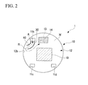
- Fig. 2 is a sectional view taken along the line I-I in Fig. 1 .
- the reactor containment structure 1 is provided with a reactor containment vessel 10 which contains a nuclear power reactor 5 and also with a circulating pump (pumping device, pump body) 20.
- the reactor containment vessel 10 is provide with a reactor containment chamber 11 which contains the nuclear power reactor 5 and also with a pool (sump pool) 12 in which emergency cooling water (emergency cooling liquid) W is stored.
- the reactor containment chamber 11 is installed inside the reactor containment vessel 10.
- the reactor containment chamber 11 contains a steam generator, a pressurizer, and so on, which are not illustrated, together with the nuclear power reactor 5.
- opening parts 11b, 11c, 11d communicate with a lower floor are installed on a floor part 11a of the reactor containment chamber 11.
- the pool 12 is installed inside the reactor containment vessel 10 so as to be below the reactor containment chamber 11 adjacently.
- the emergency cooling water W is stored in the pool 12. That is, the pool 12 is installed on a lower floor of the reactor comtainment vessel 10 and, more specifically, installed on the basement floor of the reactor cotainment vessel 10.
- a circulation sump (sump) 13 is installed bellow a bottom part 12a of the pool 12.
- the circulation sump 13 is installed so as to be lower by one step than the bottom part 12a of the pool 12.
- the circulation sump 13 is provided with a sump screen (debris filtering body) 14 for filtering debris such as broken pieces contained in the emergency cooling water W.
- the sump screen 14 is installed so as to cover an opening part of the circulation sump 13.
- a structure 19 which is shown in Fig. 2 is a structure such as a supporting pillar, for example.
- the sump screen 14 is formed in the shape of a box in which one surface is opened.
- the sump screen 14 is installed in such a manner that the opened side is superimposed on the opening part of the circulation sump 13. That is, the sump screen 14 covers the opening part of the circulation sump 13 in a condition where the open side of the sump screen 14 is arranged lower in position than the bottom side thereof. Further, as shown in Fig. 1 , the sump screen 14 is submerged entirely for effectively utilizing entire area of the sump screen in trapping broken pieces.
- the circulating pump 20 is connected to one end part of a suction side piping 20a.
- the other end part of the suction side piping 20a is connected to the circulation sump 13 and opened at the circulation sump 13.
- the circulating pump 20 is connected to a discharge side piping 20b.
- the discharge side piping 20b is connected to spray nozzles 20c mounted at an upper part 11f of the reactor containment chamber 11.
- the reactor containment structure 1 actuates the circulating pump 20 on occurrence of a loss-of-primary-coolant accident in association with breakage of a piping part 5a of the nuclear power reactor 5.
- the circulating pump 20 sucks the emergency cooling water W stored in the pool 12 from the circulation sump 13.
- the circulating pump 20 discharged the sucked emergency cooling water W through the spray nozzles 20c installed at the upper part 11f of the reactor containment chamber 11.
- the circulating pump 20 discharges the emergency cooling water W through the spray nozzles 20c to supply the emergency cooling water W to the nuclear power reactor 5, thereby cooling the nuclear power reactor 5.
- the reactor containment structure 1 allows the emergency cooling water W in the pool 12 to circulate.
- Below the opening part 11b there are installed structures such as stairs and a ladder which are not illustrated. Due to the influence of the structures (not illustrated), the emergency cooling water W flows in the direction indicated by an arrow A in Fig. 2 (a direction from the back to the front on the space in Fig. 1 ) when flowing from the opening part 11b into the pool 12.
- the reactor containment structure I is provided with the baffle plate 30 and the auxiliary plate 40.
- the baffle plate 30 and the auxiliary plate 40 are installed below the opening part 11b which is the closest to the circulation sump 13.
- the baffle plate 30 is installed so as to extend from downward to upward from the bottom part 12a of the pool 12 to the floor part 11a of the reactor containment chamber 11.
- the baffle plate 30 is curved so as to gradually approach a wall part 12b of the pool 12, as it moves away from an end part below the opening part 11b to the direction indicated by the arrow A.
- An end part of the baffle plate 30, opposite to the opening part 11b extends up to the vicinity of the wall part 12b.
- the baffle plate 30 guides the emergency cooling water W which flows into the pool 12 from the opening part 11b in a direction spaced away from the circulation sump 13.
- the baffle plate 30 regulates the flow channel R of the emergency cooling water W which flows from the opening part 11b in a direction spaced away from the circulation sump 13.
- the emergency cooling water W which flows into the pool 12 from the opening part 11b flows along the baffle plate 30 so as to be spaced away from the circulation sump 13, as shown in Fig. 2 . That is, the emergency cooling water W flows in such a manner that a direct distance from the circulation sump 13 is gradually increased.
- the auxiliary plate 40 is installed so as to extend from downward to upward from the bottom part 12a of the pool to the floor part 11a of the reactor containment chamber 11.
- the auxiliary plate 40 is installed along the baffle plale 30 at a position which is closer to the wall part 12b than the baffle plate 30.
- the auxiliary plate 40 is curved so as to gradually approach the wall part 12b of the pool 12 as it moves away from a lower end of the opening part 11b to the direction indicated by the arrow A.
- An end part opposite to the opening part 11b of the auxiliary plate 40 extends up to the vicinity of the wall part 12b.
- the auxiliary plate 40 and the baffle plate 30 regulate the width of the flow channel R of the emergency cooling water W which flows from the opening part 11b.
- Fig. 3 is an enlarged view of the baffle plate 30 and the auxiliary plate 40.
- the baffle plate 30 and the auxiliary plate 40 are curved so that the flow channel width D which is a width of the flow channel R between the baffle plate 30 and the auxiliary plate 40 is substantially equal from one end part 30b of the baffle plate 30 to the other end part 30a thereof.
- a direct distance between the one end part 30b of the baffle plate 30 and the other end part 30a is given as L.
- the baffle plate 30 and the auxiliary plate 40 are installed in such a manner that the ratio of L/D is to be 1.2, which is a ratio of the direct distance L to the flow channel width D.
- a high-pressure primary coolant is ejected, by which debris such as broken pieces of heat-insulating materials and mental pieces is scattered inside the reactor containment chamber 11.
- the circulating pump 20 is actuated to suck the emergency cooling water W in the circulation sump 13.
- the circulating pump 20 supplies the sucked emergency cooling water W to the nuclear power realtor 5 from the spray nozzles 20c installed at the upper part 11f of the reactor containment chamber 11.
- the emergency cooling water W which has been supplied to the nuclear power reactor 5 cools the nuclear power reactor 5 and runs off the floor part 11a.
- the emergency cooling water W which has run off the floor part 11a flows into the pool 12 from the opening parts 11b, 11c, 11d, together with the debris.
- the emergency cooling water W flows between the baffle plate 30 and the auxiliary plate 40 so as to be spaced away from the circulation sump 13.
- the emergency cooling water W passes between the baffle plate 30 and the auxiliary plate 40 and, thereafter, flows toward the circulation sump 13.
- the emergency cooling water W passes through the sump screen 14 and flows into the circulation sump 13. That is, the emergency cooling water W is bypassed by the baffle plate 30 so as to be moved away from the circulation sump 3 and, thereafter, flows into the circulation sump 13.
- the baffle plate 30 is formed cursed. Therefore, the baffle plate 30 is reduced in resistance with respect to the emergency cooling water W and the emergency cooling water W flows smoothly without any stagnation of the emergency cooling water W. Further, where the ratio of L/D is smaller than 1, which is a ratio of a direct distance L between both end parts of the baffle plate 30 to the flow channel width D between the baffle plate 30 and the auxiliary plate 40, it is difficult to sufficiently bypass the flow of the emergency cooling water W.
- the baffle plate 30 becomes great in fluid loads of the emergency cooling water W to which the baffle plate 30 is subjected.
- the ratio of L/D is set to be 1.2. Therefore, the baffle plate 30 and the auxiliary plate 40 are able to sufficiently bypass the flow of the emergency cooling water W with respect to the circulation sump 13, and the flow channel R can be extended.
- the baffle plate 30 is curved, by which the fluid loads of the emergency cooling water W can be decreased to prevent the baffle plate 30 and the auxiliary plate 40 from breakage.
- the baffle plate 30 is increased in section modulus by being curved. Therefore, the baffle plate 30 can be increased in strength to prevent the baffle plate 30 from breakage. As a it it is possible to maintain the flow channel R against the fluid force of the emergency cooling water W.
- the baffle plate 30 is installed, by which the flow channel R is extended to be longer than conventional cases. Therefore, most of the debris contained in the emergency cooling water W settles on the bottom part 12a of the pool 12 and accumulates thereon while the emergency cooling water W Hows along the flow channel R. Thereby, the debris contained in the emergency cooling water W hardly reaches the sump screen 14.
- the debris hardly reaches the sump screen 14 and also hardly adheres to the sump screen 14. Therefore, the circulating pump 20 is prevented from an increase in loads, and the emergency cooling water W is then prevented from a reduction in circulation efficiency. As a result, the emergency cooling water W is favorably circulated the reactor containment structure 1 to maintain good in safety of the nuclear power reactor 5.
- a distance of the emergency cooling water W which flows into the pool 12 and reaches the sump screen 14 can be made longer by the baffle plate 30.
- the debris contained in the emergency cooling water W is made to settle on the bottom part 12a of the pool 12 on its way to the circulation sump 13, thus inhabiting arrival of the debris at the sump screen 14. It is, therefore, possible to inhibit adhesion of the debris to the sump screen 14.
- the configuration can be simplified. Therefore, according to the reactor containment structure 1 of the present embodiment, it is possible to inhibit adhesion of the debris to the sump screen 14 and simplify a configuration of the opening part 11b.
- the baffle plate 30 is curved so as to be spaced away from the circulation sump 13, it is possible to increase the strength of the baffle plate 30 to fluid loads of the emergency cooling water No to which the baffle plate 30 is subjected. Thereby, the baffle plate 30 can be made thinner. Still further, the emergency cooling water W is reduced in resistance from the baffle plate 30 and flows smoothly without stagnation of the emergency cooling water W which flows along the baffle plate 30.
- the auxiliary plate 40 for regulating the flow channel width D of the emergency cooling water W. Therefore, it is possible to present the flow of the emergency cooling water W from deceiving resistance from other structures (for example, that similar to the structure 19). In addition it is also possible to easily control the flow of the emergency cooling water W which flows into the pool 12.
- the ratio ofL/D is smaller than 1. which is a ratio of a direct distance L connecting the end part 30a of the battle plate 30 with the end part 30b thereof to the flow channel width D, it is difficult to sufficiently bypass the flow of the emergency cooling water W and guide the flow to the circulation sump 13.
- the ratio of L/D is greater than 1.5, the baffle plate 30 becomes great in fluid loads of the emergency cooling water W to which the baffle plate 30 is subjected.
- the ratio of L/D is 1.2. Therefore, the flow of the emergency cooling water W can be bypassed to guide the flow to the circulation sump 13. It is, thereby, possible to make the fluid loads of the emergency cooling water W small to which the baffle plate 30 is subjected.
- Fig. 4 is an enlarged sectional view that shows the baffle prate 31 and the auxiliary plate 41 which are modified examples of the above-described baffle plate 30 and the auxiliary plate 40.
- the baffle plate 31 is bent so as to be folded drown in a direction spaced away from the circulation sump 13 .
- the auxiliary plate 41 is installed so as to extend along the baffle plate 31, A How channel between the baffle plate 31 and the auxiliary plate 41 is substantially equal in width from one end part of the baffle plate 31 to the other end part excluding the bent part. According, to this configuration, it is possible to bend the baffle plate 31 and the auxiliary plate 41 by flexibly corresponding to the arrangement relationship with other structures (for example, that similar to the structure 19). It is also possible to easily manufacture the baffle plate 30.
- the above-described embodiment is configured in such a manner that the baffle plate 30 is installed from the bottom part 12a of the pool 12 to the floor part 11a thereof.
- the height of the baffle plate 30 from the bottom part 12a of the pool 12 suffices if the height exceeds the water level of the emergency cooling water W which has been stored in the pool 12. Thereby, as with the above-described embodiment, it is possible to inhibit arrival of the debris at the sump screen 14.
- the height of the baffle plate 30 is lower than the water level of the pool 12, it is possible to control a direction at which some of the emergency cooling water W flows. Therefore, the flow channel of the emergency cooling water W can be partially extended and the debris contained in some of the emergency cooling water W is made to settle in a greater amount compared to conventional cases. Thus, adhesion of the debris to the sump screen 14 can be inhibited at a certain percentage.
- the ratio of L/D is set to be 1.2, the ratio may be set in a range of 1.0 to 1.5.
- the baffle plate the shape of which is curved or bent
- the baffle plate may be formed straight. In this case as well, it is possible to increase an arrival distance from the opening part 11b to the circulation sump 13. Therefore, debris can be settled in a greater amount compared to conventional cases and adhesion of the debris to the sump screen 14 is inhibited.
- no baffle plate is installed below the opening parts 11c, 11d.
- a similar baffle plate may be installed below the opening parts 11c, 11d. In this case, an opening part closer to the circulation sump 13 is able to better reduce debris adhered to the sump screen 14 than a case where no battle plate is installed.
- the present invention relates to a reactor containment structure which is provided with a reactor containment vessel, a reactor containment chamber which is installed inside the reactor containment vessel to contain a nuclear power reactor, a pool which is installed inside the reactor containment vessel so as to be below the reactor containment chamber adjacently and in which an emergency cooling liquid is stored, an opening part which allows the emergency cooling liquid to flow into the pool from the reactor containment chamber, a sump which is installed below the pool, a debris filtering body which is installed at the sump to filter debris contained in the emergency cooling liquid, a pumping device which sucks the emergency cooling liquid from the sump to discharge the emergency cooling liquid into the reactor containment chamber, and a baffle plate which guides the emergency cooling liquid that Hows into the pool from the opening part in a direction spaced away from the sump, according to the reactor containment structure of the present intention, it is possible to inhibit adhesion of the debris to the debris filtering body and simplify a configuration of the opening part at a companionway (hatch) installed between the pool and the reactor
Landscapes
- Physics & Mathematics (AREA)
- Engineering & Computer Science (AREA)
- Plasma & Fusion (AREA)
- General Engineering & Computer Science (AREA)
- High Energy & Nuclear Physics (AREA)
- Business, Economics & Management (AREA)
- Emergency Management (AREA)
- Structure Of Emergency Protection For Nuclear Reactors (AREA)
Abstract
The reactor containment structure is provides with a reactor containment vessel (10), a reactor containment chamber (11) which is installed inside the reactor containment vessel (10) to contain a nuclear power reactor (5), a pool (12) which is installed inside the reactor containment vessel (10) so as to be below the reactor containment chamber (11) adjacently and in which an emergency cooling liquid (W) is stored, an opening part (11b) which allows the emergency cooling liquid (W) to flow into the pool (12) from the reactor containment chamber (11), a sump (13) which is installed below the pool (12), a debris filtering body (14) which is installed at the sump (13) to filter debris contained in the emergency cooling liquid (W), a pumping device (20) which sucks the emergency cooling liquid (W) from the sump (13) and discharges the emergency cooling liquid (W) into the reactor containment chamber (11) and a baffle plate (30) which guides the emergency cooling liquid (W) that flows into the pool (12) from the opening part (11b) in a direction spaced away from the sump (13).
Description
- The present invention relates to a reactor containment structure which is used in a pressurized water reactor.
The application concerted is to claim the right of priority to Japanese Patent Application No.2009-122495 filed on May 20, 2009 - As widely known, in a pressurized water reactor, pressure is applied so as not to boil a primary coolant (light water). The primary coolant is heated by thermal energy generate by nuclear fission reactions of a nuclear power reactor and the heated primary coolant heated to a high temperature is fed to a steam generator. Thereby, a secondary coolant (light water) is boiled to notate a turbine generator with high temperature and high pressure steam, thereby generating electric power.
- In such a pressurized water reactor, a safety structure is adapted in order to prevent a nuclear power reactor from being excessively heated on occurrence of a loss-of-primary-coolant accident. The safety structure is provided mainly with a reactor containment vessel and a pumping device.
The reactor containment vessel is provide mainly with a reactor containment chamber, a pool (sump pool) and a sump. The reactor containment chamber contains a nuclear power reactor. The pool is installed inside the reactor containment vessel so as to be below the reactor containment chamber adjacently, and an emergency cooling liquid is stored in the pool. The sump is installed at a lower part of the pool. Further, at a lower part of the reactor containment chamber, there is installed an opening part for allowing the emergency cooling liquid inside the reactor containment chamber to flow into the pool.
The pumping device sucks the emergency cooling liquid from the sump and discharges the liquid from an upper part of the reactor containment chamber.
In the above-described safety structure, the emergency cooling liquid is sucked by the pumping device from the sump at the lower part of the pool and discharged from the upper part of the reactor containment chamber. The discharged emergency cooling liquid flows into the pool from the opening part of the reactor containment chamber. In addition, the discharged cooling liquid is again sucked by the pumping device to circulate inside the safety structure. - In the above-described safely structure, on occurrence of a loss-of-primary-cootant accident, ejection of a high-pressure primary coolant produces debris such as pieces of heat-insulating materials and metal pieces, and the debris flows into the pool. Therefore, a debris filtering body such as a sump screen is installed at the sump so that no debris is sucked into the pumping device. However, a large quantity of the debris adhered to the debris filtering body will result in an increase in load of the pumping device or a reduction in circulation efficiency. Therefore, it is desirable to avoid adhesion of a large quantity of debris to the debris filtering body.
- For example, the reactor containment structure disclosed in Patent Document I below is provided at an opening on a floor of a reactor containment chamber with a second sump which functions as a temporary storage tank for emergency cooling water. Further, a second screen is installed at a part where water flows from the second sump to the pool, That is, debris is trapped by the second screen so as not to flow into the pool, thereby inhabiting adhesion of the debris to the sump screen.
- Patent Document 1: Japanese Published Unexamined Patent Application No.
H7-260977 - However, the above-described pressurized water reactor has a problem that it is impossible to install the second sump at every opening. That is, it is structurally impossibly to install the above-described second sump, for example, at an opening part of a companionway (hatch) installed between the pool and the reactor containment chamber. Further, it can be considered to configure the opening part openable/closable. However, if the opening part of the companionway (hatch) is made openable/closable, there are problem such as a reduction in maintenance performance and a reduction in circulation efficiency of emergency cooling water.
- The present invention providers a reactor containment structure which is capable of inhibiting adhesion of debris to a debris filtering body and simplifying a configuration of an opening part.
- In order to achieve the above object, the reactor containment structure of the present invention is configured with the following:
- a reactor containment vessel which is provide with a reactor containment chamber halving an opening part communicate with a lower floor at a lower part of a room containing a nuclear power reactor, a sump pool installed on the lower floor to store an emergency cooling liquid, and a sump installed at a lower part of the sump pool;
- a debris filtering body which is installed at the sump; and
- a pump body which sucks the emergency cooling liquid from the sump to discharge the emergency cooling liquid from an upper part of the reactor containment chamber.
- a reactor containment vessel;
- a reactor containment chamber which is installed inside the reactor containment vessel to contain a nuclear power reactor;
- a pool which is installed inside the reactor containment vessel so as to be below the reactor containment chamber adjacently and in which an emergency cooling liquid is stored;
- an opening part which allows the emergency cooling liquid to flow from the reactor containment chamber to the pool;
- a sump which is installed below the pool;
- a debris filtering body which is installed at the sump to filter debris contained in the emergency cooling liquid,
- a pumping device which sucks the emergency cooling liquid from the sump and discharges the emergency cooling liquid into the reactor containment chamber; and
- a baffle plate for guiding the emergency cooling liquid which flows into the pool from the opening part in a direction spaced away from the sump.
- The baffle plate may be curved in a direction spaced away from the sump. That is, the baffle plate may be curved and spaced away from the sump.
According to this configuration, it is possible to increase the strength of the baffle plate in relation to fluid loads of the emergency cooling liquid which flows into the pool to which the baffle plate is subjected. Accordingly, the baffle plate can be made thinned.
Further, the baffle plate is reduced in resistance with respect to the emergency cooling liquid, by which the emergency cooling liquid flows smoothly without stagnation. - The baffle plate may be bent in a direction spaced away from the sump. That is, the baffle plate may be spaced away from the sump so as to be folded down.
According to this configuration, it is possible to manufacture the baffle plate easily. - Still further, there may be installed along the baffle plate an auxiliary plate that regulates the flow channel width of the emergency cooling liquid.
According to this configuration, it is possible to easily control the flow of the emergency cooling liquid which floes into the pool. - The baffle plate may be installed in such a manner the ratio of L/D is from 1 to 1.5, which is a ratio of a direct distance (direct dimension) L connecting the both end parts of the baffle plate in a direction at which the emergency cooling liquid flows to the How channel width D.
According to this configuration, it is possible to make the fluid loads of the emergency cooling liquid small to which the baffle plate is subjected. - According to the reactor containment structure of the present intention, it is possible to inhibit adhesion of debris to the debris filtering body and simplify a configuration of the opening part.
-
-
Fig. 1 is a schematic view of a reactor containment structure 1 of an embodiment of the present intention. -
Fig. 2 is a sectional view which shows major parts of the reactor containment structure 1 of the embodiment of the present invention, and a sectional view taken along the line I-I inFig. 1 . -
Fig. 3 is an enlarged sectional view which shows major parts of the reactor containment structure I of the embodiment of the present intention, and an enlarged sectional view of abaffle plate 30 and anauxiliary plate 40. -
Fig. 4 is an enlarged sectional view of abaffle plate 31 and anauxiliary plate 41 which are modified examples of thebaffle plate 30 and theauxiliary plate 40 of the embodiment of the present invention. - A description will be given of the embodiment of the present invention with reference to the drawings.
Fig. 1 is a schematic view which shows the reactor containment structure 1 of the embodiment of the present invention.Fig. 2 is a sectional view taken along the line I-I inFig. 1 .
As shown inFig. 1 , the reactor containment structure 1 is provided with areactor containment vessel 10 which contains anuclear power reactor 5 and also with a circulating pump (pumping device, pump body) 20. - The
reactor containment vessel 10 is provide with areactor containment chamber 11 which contains thenuclear power reactor 5 and also with a pool (sump pool) 12 in which emergency cooling water (emergency cooling liquid) W is stored.
Thereactor containment chamber 11 is installed inside thereactor containment vessel 10. Thereactor containment chamber 11 contains a steam generator, a pressurizer, and so on, which are not illustrated, together with thenuclear power reactor 5. As shown inFig. 1 andFig. 2 , openingparts floor part 11a of thereactor containment chamber 11. - The
pool 12 is installed inside thereactor containment vessel 10 so as to be below thereactor containment chamber 11 adjacently. The emergency cooling water W is stored in thepool 12. That is, thepool 12 is installed on a lower floor of thereactor comtainment vessel 10 and, more specifically, installed on the basement floor of thereactor cotainment vessel 10.
As shown inFig. 1 . a circulation sump (sump) 13 is installed bellow abottom part 12a of thepool 12. Thecirculation sump 13 is installed so as to be lower by one step than thebottom part 12a of thepool 12. Thecirculation sump 13 is provided with a sump screen (debris filtering body) 14 for filtering debris such as broken pieces contained in the emergency cooling water W. Thesump screen 14 is installed so as to cover an opening part of thecirculation sump 13.
Astructure 19 which is shown inFig. 2 is a structure such as a supporting pillar, for example. - The
sump screen 14 is formed in the shape of a box in which one surface is opened. Thesump screen 14 is installed in such a manner that the opened side is superimposed on the opening part of thecirculation sump 13. That is, thesump screen 14 covers the opening part of thecirculation sump 13 in a condition where the open side of thesump screen 14 is arranged lower in position than the bottom side thereof. Further, as shown inFig. 1 , thesump screen 14 is submerged entirely for effectively utilizing entire area of the sump screen in trapping broken pieces.
In place of thesump screen 14. there may be used a debris filtering body in which plate members halving through holes are stacked in a multiple stage. - As shown in
Fig. 1 . the circulatingpump 20 is connected to one end part of asuction side piping 20a. The other end part of thesuction side piping 20a is connected to thecirculation sump 13 and opened at thecirculation sump 13. Further, the circulatingpump 20 is connected to adischarge side piping 20b. Thedischarge side piping 20b is connected to spraynozzles 20c mounted at anupper part 11f of thereactor containment chamber 11. - The reactor containment structure 1 actuates the circulating
pump 20 on occurrence of a loss-of-primary-coolant accident in association with breakage of apiping part 5a of thenuclear power reactor 5. The circulatingpump 20 sucks the emergency cooling water W stored in thepool 12 from thecirculation sump 13. The circulatingpump 20 discharged the sucked emergency cooling water W through thespray nozzles 20c installed at theupper part 11f of thereactor containment chamber 11. The circulatingpump 20 discharges the emergency cooling water W through thespray nozzles 20c to supply the emergency cooling water W to thenuclear power reactor 5, thereby cooling thenuclear power reactor 5. - The emergency cooling water W which has cooled the
nuclear power reactors 5 and runs off thefloor part 11a flows into thepool 12 from the openingparts
I 1d. As described so far, the reactor containment structure 1 allows the emergency cooling water W in thepool 12 to circulate.
Here, below theopening part 11b, there are installed structures such as stairs and a ladder which are not illustrated. Due to the influence of the structures (not illustrated), the emergency cooling water W flows in the direction indicated by an arrow A inFig. 2 (a direction from the back to the front on the space inFig. 1 ) when flowing from theopening part 11b into thepool 12. - As shown in
Fig. 1 andFig. 2 , the reactor containment structure I is provided with thebaffle plate 30 and theauxiliary plate 40. Thebaffle plate 30 and theauxiliary plate 40 are installed below theopening part 11b which is the closest to thecirculation sump 13.
As shown inFig. 1 , thebaffle plate 30 is installed so as to extend from downward to upward from thebottom part 12a of thepool 12 to thefloor part 11a of thereactor containment chamber 11. As shown inFig. 2 , thebaffle plate 30 is curved so as to gradually approach awall part 12b of thepool 12, as it moves away from an end part below theopening part 11b to the direction indicated by the arrow A. An end part of thebaffle plate 30, opposite to theopening part 11b, extends up to the vicinity of thewall part 12b. - The
baffle plate 30 guides the emergency cooling water W which flows into thepool 12 from theopening part 11b in a direction spaced away from thecirculation sump 13. In other words, thebaffle plate 30 regulates the flow channel R of the emergency cooling water W which flows from theopening part 11b in a direction spaced away from thecirculation sump 13. Thereby, the emergency cooling water W which flows into thepool 12 from theopening part 11b flows along thebaffle plate 30 so as to be spaced away from thecirculation sump 13, as shown inFig. 2 . That is, the emergency cooling water W flows in such a manner that a direct distance from thecirculation sump 13 is gradually increased. - As shown in
Fig. 1 , theauxiliary plate 40 is installed so as to extend from downward to upward from thebottom part 12a of the pool to thefloor part 11a of thereactor containment chamber 11. As shown inFig. 2 , theauxiliary plate 40 is installed along thebaffle plale 30 at a position which is closer to thewall part 12b than thebaffle plate 30. Theauxiliary plate 40 is curved so as to gradually approach thewall part 12b of thepool 12 as it moves away from a lower end of theopening part 11b to the direction indicated by the arrow A. An end part opposite to theopening part 11b of theauxiliary plate 40 extends up to the vicinity of thewall part 12b.
In the present embodiment, theauxiliary plate 40 and thebaffle plate 30 regulate the width of the flow channel R of the emergency cooling water W which flows from theopening part 11b. -
Fig. 3 is an enlarged view of thebaffle plate 30 and theauxiliary plate 40.
As shown inFig. 3 , thebaffle plate 30 and theauxiliary plate 40 are curved so that the flow channel width D which is a width of the flow channel R between thebaffle plate 30 and theauxiliary plate 40 is substantially equal from oneend part 30b of thebaffle plate 30 to theother end part 30a thereof. Here, a direct distance between the oneend part 30b of thebaffle plate 30 and theother end part 30a is given as L. At this time, thebaffle plate 30 and theauxiliary plate 40 are installed in such a manner that the ratio of L/D is to be 1.2, which is a ratio of the direct distance L to the flow channel width D. - In the reactor containment structure 1 shown in
Fig. 1 , on occurrence of a loss-of-primary-coolant accident, a high-pressure primary coolant is ejected, by which debris such as broken pieces of heat-insulating materials and mental pieces is scattered inside thereactor containment chamber 11.
At this time, the circulatingpump 20 is actuated to suck the emergency cooling water W in thecirculation sump 13. The circulatingpump 20 supplies the sucked emergency cooling water W to thenuclear power realtor 5 from thespray nozzles 20c installed at theupper part 11f of thereactor containment chamber 11. The emergency cooling water W which has been supplied to thenuclear power reactor 5 cools thenuclear power reactor 5 and runs off thefloor part 11a. The emergency cooling water W which has run off thefloor part 11a flows into thepool 12 from the openingparts - The emergency cooling water W which flows into the
pool 12 from theopening part 11b flows inside thepool 12 along the flow channel R as shown inFig. 2 .
First, the emergency cooling water W flows between thebaffle plate 30 and theauxiliary plate 40 so as to be spaced away from thecirculation sump 13. The emergency cooling water W passes between thebaffle plate 30 and theauxiliary plate 40 and, thereafter, flows toward thecirculation sump 13. Then, the emergency cooling water W passes through thesump screen 14 and flows into thecirculation sump 13. That is, the emergency cooling water W is bypassed by thebaffle plate 30 so as to be moved away from the circulation sump 3 and, thereafter, flows into thecirculation sump 13. - When the emergency cooling water flows from the
opening part 11b to thepool 12, the fluid loads are exerted from the emergency cooling water W to thebaffle plate 30. Here, thebaffle plate 30 is formed cursed. Therefore, thebaffle plate 30 is reduced in resistance with respect to the emergency cooling water W and the emergency cooling water W flows smoothly without any stagnation of the emergency cooling water W.
Further, where the ratio of L/D is smaller than 1, which is a ratio of a direct distance L between both end parts of thebaffle plate 30 to the flow channel width D between thebaffle plate 30 and theauxiliary plate 40, it is difficult to sufficiently bypass the flow of the emergency cooling water W. Also where the ratio of L/D is greater than 1.5, thebaffle plate 30 becomes great in fluid loads of the emergency cooling water W to which thebaffle plate 30 is subjected. In the present embodiment, the ratio of L/D is set to be 1.2. Therefore, thebaffle plate 30 and theauxiliary plate 40 are able to sufficiently bypass the flow of the emergency cooling water W with respect to thecirculation sump 13, and the flow channel R can be extended.
Stilt further, thebaffle plate 30 is curved, by which the fluid loads of the emergency cooling water W can be decreased to prevent thebaffle plate 30 and theauxiliary plate 40 from breakage. In addition, thebaffle plate 30 is increased in section modulus by being curved. Therefore, thebaffle plate 30 can be increased in strength to prevent thebaffle plate 30 from breakage. As a it it is possible to maintain the flow channel R against the fluid force of the emergency cooling water W. - As the flow channel R of the emergency cooling water W which flows into the
pool 12 from theopening part 11b and reaches thecirculation sump 13 is longer in distance, debris contained in the emergency cooling water W settles on thebottom part 12a of thepool 12 is accordingly increased in amount. In the present embodiment, thebaffle plate 30 is installed, by which the flow channel R is extended to be longer than conventional cases. Therefore, most of the debris contained in the emergency cooling water W settles on thebottom part 12a of thepool 12 and accumulates thereon while the emergency cooling water W Hows along the flow channel R. Thereby, the debris contained in the emergency cooling water W hardly reaches thesump screen 14. - As described so far, the debris hardly reaches the
sump screen 14 and also hardly adheres to thesump screen 14. Therefore, the circulatingpump 20 is prevented from an increase in loads, and the emergency cooling water W is then prevented from a reduction in circulation efficiency. As a result, the emergency cooling water W is favorably circulated the reactor containment structure 1 to maintain good in safety of thenuclear power reactor 5. - As so far described, in the reactor containment structure 1 of the present embodiment, a distance of the emergency cooling water W which flows into the
pool 12 and reaches thesump screen 14 can be made longer by thebaffle plate 30. Thereby, the debris contained in the emergency cooling water W is made to settle on thebottom part 12a of thepool 12 on its way to thecirculation sump 13, thus inhabiting arrival of the debris at thesump screen 14. It is, therefore, possible to inhibit adhesion of the debris to thesump screen 14.
Further, since a necessity for installing a sump structure at theopening part 11b or installing an opening/closing mechanism is eliminated, the configuration can be simplified.
Therefore, according to the reactor containment structure 1 of the present embodiment, it is possible to inhibit adhesion of the debris to thesump screen 14 and simplify a configuration of theopening part 11b. - Further, since the
baffle plate 30 is curved so as to be spaced away from thecirculation sump 13, it is possible to increase the strength of thebaffle plate 30 to fluid loads of the emergency cooling water No to which thebaffle plate 30 is subjected. Thereby, thebaffle plate 30 can be made thinner.
Still further, the emergency cooling water W is reduced in resistance from thebaffle plate 30 and flows smoothly without stagnation of the emergency cooling water W which flows along thebaffle plate 30. - In addition, there is installed along the
baffle plate 30 theauxiliary plate 40 for regulating the flow channel width D of the emergency cooling water W. Therefore, it is possible to present the flow of the emergency cooling water W from deceiving resistance from other structures (for example, that similar to the structure 19). In addition it is also possible to easily control the flow of the emergency cooling water W which flows into thepool 12. - Here, where the ratio ofL/D is smaller than 1. which is a ratio of a direct distance L connecting the
end part 30a of thebattle plate 30 with theend part 30b thereof to the flow channel width D, it is difficult to sufficiently bypass the flow of the emergency cooling water W and guide the flow to thecirculation sump 13. Further, where the ratio of L/D is greater than 1.5, thebaffle plate 30 becomes great in fluid loads of the emergency cooling water W to which thebaffle plate 30 is subjected.
In the present embodiment, the ratio of L/D is 1.2. Therefore, the flow of the emergency cooling water W can be bypassed to guide the flow to thecirculation sump 13. It is, thereby, possible to make the fluid loads of the emergency cooling water W small to which thebaffle plate 30 is subjected. -
Fig. 4 is an enlarged sectional view that shows the baffle prate 31 and theauxiliary plate 41 which are modified examples of the above-describedbaffle plate 30 and theauxiliary plate 40.
As shown inFig. 4 , thebaffle plate 31 is bent so as to be folded drown in a direction spaced away from thecirculation sump 13 . Theauxiliary plate 41 is installed so as to extend along thebaffle plate 31, A How channel between thebaffle plate 31 and theauxiliary plate 41 is substantially equal in width from one end part of thebaffle plate 31 to the other end part excluding the bent part.
According, to this configuration, it is possible to bend thebaffle plate 31 and theauxiliary plate 41 by flexibly corresponding to the arrangement relationship with other structures (for example, that similar to the structure 19). It is also possible to easily manufacture thebaffle plate 30. - Procedures, shapes and combinations of individual members shown in the above-described embodiments are only examples and can be modified in various ways based on design requirements, and so on, within a scope not departing from the gist of the present intention.
For example, the above-described embodiment is configured in such a manner that thebaffle plate 30 is installed from thebottom part 12a of thepool 12 to thefloor part 11a thereof. However, the height of thebaffle plate 30 from thebottom part 12a of thepool 12 suffices if the height exceeds the water level of the emergency cooling water W which has been stored in thepool 12. Thereby, as with the above-described embodiment, it is possible to inhibit arrival of the debris at thesump screen 14.
Further, even where the height of thebaffle plate 30 is lower than the water level of thepool 12, it is possible to control a direction at which some of the emergency cooling water W flows. Therefore, the flow channel of the emergency cooling water W can be partially extended and the debris contained in some of the emergency cooling water W is made to settle in a greater amount compared to conventional cases. Thus, adhesion of the debris to thesump screen 14 can be inhibited at a certain percentage. - Further, although in the above-described embodiment, the ratio of L/D is set to be 1.2, the ratio may be set in a range of 1.0 to 1.5.
- Still further, in the above-described embodiment, a description has been given of the baffle plate, the shape of which is curved or bent, However, the baffle plate may be formed straight. In this case as well, it is possible to increase an arrival distance from the
opening part 11b to thecirculation sump 13. Therefore, debris can be settled in a greater amount compared to conventional cases and adhesion of the debris to thesump screen 14 is inhibited. - In addition, in the above-described embodiment, no baffle plate is installed below the opening
parts parts circulation sump 13 is able to better reduce debris adhered to thesump screen 14 than a case where no battle plate is installed. - A description has been so far made for preferred embodiments of the present intention, to which the present invention shall not be, however, restricted. The present invention may be subjected to addition, omission, replacement and other modifications of the configuration within a scope not deporting from the gist of the present invention. The present invention shall not be restricted to the above description but will be restricted only by the scope of the adhered claims.
- The present invention relates to a reactor containment structure which is provided with a reactor containment vessel, a reactor containment chamber which is installed inside the reactor containment vessel to contain a nuclear power reactor, a pool which is installed inside the reactor containment vessel so as to be below the reactor containment chamber adjacently and in which an emergency cooling liquid is stored, an opening part which allows the emergency cooling liquid to flow into the pool from the reactor containment chamber, a sump which is installed below the pool, a debris filtering body which is installed at the sump to filter debris contained in the emergency cooling liquid, a pumping device which sucks the emergency cooling liquid from the sump to discharge the emergency cooling liquid into the reactor containment chamber, and a baffle plate which guides the emergency cooling liquid that Hows into the pool from the opening part in a direction spaced away from the sump, according to the reactor containment structure of the present intention, it is possible to inhibit adhesion of the debris to the debris filtering body and simplify a configuration of the opening part at a companionway (hatch) installed between the pool and the reactor containment chamber.
-
- 1: reactor containment structure
- 5: nuclear power reactor
- 10: reactor containment vessel
- 11: reactor containment chamber
- 11a: floor part
- 11b. 11c and 11d: opening part
- 11f: upper part
- 12: pool (sump pool)
- 13: recirculation sump (sump)
- 14: sump screen (debris filtering body)
- 20: recirculating (pumping device, pump body)
- 30, 31: baffle plate
- 30a. 30b: both end parts
- 40, 41: auxiliary plate
- D: flow channel width
- L: direct distance dimension
- R: flow channel
- W: emergency cooling water (emergency cooling liquid)
In the reactor containment structure of the present invention, a baffle plate is installed for regulating a flow channel of the emergency cooling liquid which flows again into the sump pool in such a direction that is spaced away from the sump.
That is, in order to solve the above problems, the reactor containment structure of the present invention is configured with the following:
Further, since a necessity for installing a sump structure at an opening part or an opening/closing mechanism is eliminated, the opening part can be simplified in configuration.
Therefore, according to the reactor containment structure of the present invention, it is possible to inhibit adhesion of the debris to the debris filtering body and simplify a configuration of the opening part.
Claims (5)
- A reactor containment structure comprising:a reactor containment vessel;a reactor containment chamber which is installed inside the reactor containment vessel to contain a nuclear power reactor;a pool which is installed inside the reactor containment vessel so as to be below the reactor containment chamber adjacently and in which an emergency cooling liquid is stored;an opening part which allows the emergency cooling liquid to flow into the pool from the reactor containment chamber;a sump which is installed below the pool;a debris filtering body which is installed at the sump to filter debris contained in the emergency cooling liquid;a pumping device which sucks the emergency cooling liquid from the sump to discharge the emergency cooling liquid into the reactor containment chamber; anda baffle plate which guides the emergency cooling liquid that flows into the pool from the opening part in a direction spaced away from the sump.
- The reactor containment structure according to claim 1, wherein the baffle plate is curved in a direction spaced away from the sump.
- The reactor containment structure according to claim 1, wherein the baffle plate is bent in a direction spaced away from the sump.
- The reactor containment structure according to claim 2 or claim 3, wherein an auxiliary plate for regulating a flow channel width of the emergency cooling liquid is installed along the baffle plate.
- The reactor containment structure according to claim 4, wherein the baffle plate is from 1 to 1.5 in a ratio of L/D, which is a ratio of a direct distance L connecting both end pans of the baffle plate in a direction at which the emergency cooling liquid flows to the flow channel width D.
Applications Claiming Priority (2)
| Application Number | Priority Date | Filing Date | Title |
|---|---|---|---|
| JP2009122495A JP2010271147A (en) | 2009-05-20 | 2009-05-20 | Nuclear reactor containment structure |
| PCT/JP2010/003211 WO2010134291A1 (en) | 2009-05-20 | 2010-05-12 | Nuclear reactor containment structure |
Publications (1)
| Publication Number | Publication Date |
|---|---|
| EP2434497A1 true EP2434497A1 (en) | 2012-03-28 |
Family
ID=43125984
Family Applications (1)
| Application Number | Title | Priority Date | Filing Date |
|---|---|---|---|
| EP10777530A Withdrawn EP2434497A1 (en) | 2009-05-20 | 2010-05-12 | Nuclear reactor containment structure |
Country Status (6)
| Country | Link |
|---|---|
| US (1) | US20120051487A1 (en) |
| EP (1) | EP2434497A1 (en) |
| JP (1) | JP2010271147A (en) |
| KR (1) | KR20120013391A (en) |
| CA (1) | CA2761518A1 (en) |
| WO (1) | WO2010134291A1 (en) |
Families Citing this family (4)
| Publication number | Priority date | Publication date | Assignee | Title |
|---|---|---|---|---|
| WO2012145020A1 (en) | 2011-04-21 | 2012-10-26 | Performance Contracting, Inc. | Multimodal debris trap |
| JP2013156195A (en) * | 2012-01-31 | 2013-08-15 | Mitsubishi Heavy Ind Ltd | Water pit structure for nuclear reactor fuel replacement |
| US9738440B2 (en) * | 2012-12-20 | 2017-08-22 | Ge-Hitachi Nuclear Energy Americas Llc | Entrainment-reducing assembly, system including the assembly, and method of reducing entrainment of gases with the assembly |
| JP6655292B2 (en) * | 2015-02-04 | 2020-02-26 | 三菱重工業株式会社 | Reactor containment structure |
Family Cites Families (6)
| Publication number | Priority date | Publication date | Assignee | Title |
|---|---|---|---|---|
| JPS554535A (en) * | 1978-06-27 | 1980-01-14 | Nippon Atomic Ind Group Co | Vent mechanism |
| JPH02122300A (en) * | 1988-11-01 | 1990-05-09 | Toshiba Corp | Reactor container |
| JPH07174880A (en) * | 1993-12-20 | 1995-07-14 | Toshiba Corp | Reactor containment vessel and its reactor plant |
| JPH07248392A (en) * | 1994-03-09 | 1995-09-26 | Toshiba Corp | Containment vessel |
| JPH07260977A (en) * | 1994-03-18 | 1995-10-13 | Mitsubishi Heavy Ind Ltd | Recirculation sump structure in water pit for fuel replacement |
| ATE316413T1 (en) * | 2004-01-29 | 2006-02-15 | Cci Ag | PROTECTIVE SCREEN FOR SHIELDING A SUCTION ROOM |
-
2009
- 2009-05-20 JP JP2009122495A patent/JP2010271147A/en not_active Withdrawn
-
2010
- 2010-05-12 EP EP10777530A patent/EP2434497A1/en not_active Withdrawn
- 2010-05-12 US US13/319,537 patent/US20120051487A1/en not_active Abandoned
- 2010-05-12 CA CA2761518A patent/CA2761518A1/en not_active Abandoned
- 2010-05-12 KR KR1020117027317A patent/KR20120013391A/en not_active Ceased
- 2010-05-12 WO PCT/JP2010/003211 patent/WO2010134291A1/en not_active Ceased
Non-Patent Citations (1)
| Title |
|---|
| See references of WO2010134291A1 * |
Also Published As
| Publication number | Publication date |
|---|---|
| JP2010271147A (en) | 2010-12-02 |
| WO2010134291A1 (en) | 2010-11-25 |
| US20120051487A1 (en) | 2012-03-01 |
| KR20120013391A (en) | 2012-02-14 |
| CA2761518A1 (en) | 2010-11-25 |
Similar Documents
| Publication | Publication Date | Title |
|---|---|---|
| EP2434496A1 (en) | Nuclear reactor containment structure | |
| US20120051487A1 (en) | Reactor containment structure | |
| US10290379B2 (en) | Passive containment cooling and filtered venting system, and nuclear power plant | |
| EP2434495A1 (en) | Nuclear reactor containment structure | |
| US5265136A (en) | Sodium cooled fast reactor | |
| EP0531086A1 (en) | Reactor core isolation cooling system | |
| CN1892922A (en) | Reactor containment shell and boiling water reactor power plant | |
| CA2846055A1 (en) | Pressurized water reactor with compact passive safety systems | |
| CN109643587B (en) | Nuclear reactor provided with a raised heat exchanger | |
| US11915836B2 (en) | Cooling system in a nuclear plant | |
| US9938942B2 (en) | Fuel supply system | |
| KR100934024B1 (en) | Safety injection tank | |
| CN110544543A (en) | safety water protection device and reactor with same | |
| EP2738032B1 (en) | Tank system for a motor vehicle | |
| EP3447834B1 (en) | Container-type battery | |
| US8739722B2 (en) | Tank arrangement adapted for a submersible pump | |
| SE508996C2 (en) | A nuclear reactor plant | |
| KR102401319B1 (en) | redox flow battery | |
| KR100266506B1 (en) | Reactor cavity flooding system | |
| JP7105719B2 (en) | ATWS countermeasure equipment and natural circulation boiling water reactor equipped with it | |
| JP7363745B2 (en) | gas liquid separator | |
| CA3029766C (en) | Nuclear reactor provided with raised heat exchanger | |
| JPH0755978A (en) | Water injection device for reactor containment cooling system | |
| WO2007056028A2 (en) | Trash rack for nuclear power plant |
Legal Events
| Date | Code | Title | Description |
|---|---|---|---|
| PUAI | Public reference made under article 153(3) epc to a published international application that has entered the european phase |
Free format text: ORIGINAL CODE: 0009012 |
|
| 17P | Request for examination filed |
Effective date: 20111117 |
|
| AK | Designated contracting states |
Kind code of ref document: A1 Designated state(s): AL AT BE BG CH CY CZ DE DK EE ES FI FR GB GR HR HU IE IS IT LI LT LU LV MC MK MT NL NO PL PT RO SE SI SK SM TR |
|
| DAX | Request for extension of the european patent (deleted) | ||
| STAA | Information on the status of an ep patent application or granted ep patent |
Free format text: STATUS: THE APPLICATION HAS BEEN WITHDRAWN |
|
| 18W | Application withdrawn |
Effective date: 20130109 |