EP2434468A1 - Assistance system for a vehicle to generate overtaking instructions - Google Patents
Assistance system for a vehicle to generate overtaking instructions Download PDFInfo
- Publication number
- EP2434468A1 EP2434468A1 EP11182120A EP11182120A EP2434468A1 EP 2434468 A1 EP2434468 A1 EP 2434468A1 EP 11182120 A EP11182120 A EP 11182120A EP 11182120 A EP11182120 A EP 11182120A EP 2434468 A1 EP2434468 A1 EP 2434468A1
- Authority
- EP
- European Patent Office
- Prior art keywords
- vehicle
- module
- overtaking
- assistance system
- distance
- Prior art date
- Legal status (The legal status is an assumption and is not a legal conclusion. Google has not performed a legal analysis and makes no representation as to the accuracy of the status listed.)
- Granted
Links
Images


Classifications
-
- G—PHYSICS
- G08—SIGNALLING
- G08G—TRAFFIC CONTROL SYSTEMS
- G08G1/00—Traffic control systems for road vehicles
- G08G1/16—Anti-collision systems
- G08G1/161—Decentralised systems, e.g. inter-vehicle communication
- G08G1/163—Decentralised systems, e.g. inter-vehicle communication involving continuous checking
-
- B—PERFORMING OPERATIONS; TRANSPORTING
- B60—VEHICLES IN GENERAL
- B60W—CONJOINT CONTROL OF VEHICLE SUB-UNITS OF DIFFERENT TYPE OR DIFFERENT FUNCTION; CONTROL SYSTEMS SPECIALLY ADAPTED FOR HYBRID VEHICLES; ROAD VEHICLE DRIVE CONTROL SYSTEMS FOR PURPOSES NOT RELATED TO THE CONTROL OF A PARTICULAR SUB-UNIT
- B60W30/00—Purposes of road vehicle drive control systems not related to the control of a particular sub-unit, e.g. of systems using conjoint control of vehicle sub-units
- B60W30/08—Active safety systems predicting or avoiding probable or impending collision or attempting to minimise its consequences
-
- G—PHYSICS
- G01—MEASURING; TESTING
- G01S—RADIO DIRECTION-FINDING; RADIO NAVIGATION; DETERMINING DISTANCE OR VELOCITY BY USE OF RADIO WAVES; LOCATING OR PRESENCE-DETECTING BY USE OF THE REFLECTION OR RERADIATION OF RADIO WAVES; ANALOGOUS ARRANGEMENTS USING OTHER WAVES
- G01S13/00—Systems using the reflection or reradiation of radio waves, e.g. radar systems; Analogous systems using reflection or reradiation of waves whose nature or wavelength is irrelevant or unspecified
- G01S13/88—Radar or analogous systems specially adapted for specific applications
- G01S13/93—Radar or analogous systems specially adapted for specific applications for anti-collision purposes
- G01S13/931—Radar or analogous systems specially adapted for specific applications for anti-collision purposes of land vehicles
-
- G—PHYSICS
- G08—SIGNALLING
- G08G—TRAFFIC CONTROL SYSTEMS
- G08G1/00—Traffic control systems for road vehicles
- G08G1/16—Anti-collision systems
- G08G1/161—Decentralised systems, e.g. inter-vehicle communication
Definitions
- the present invention relates to an assistance system for a vehicle according to the preamble of the independent claim.
- Such systems comprise inter alia cruise control systems catering for the topography of the road ahead, and lane departure warning systems which monitor the vehicle's position on the road.
- US 2008/0027607 refers to a system for making it easier to overtake which takes into account inter alia the speeds of the vehicles involved.
- EP 2,169,649 refers to an assisting system for helping a driver to plan an overtaking manoeuvre.
- the system takes into account the intended itinerary for the vehicle which is to be overtaken. This is communicated wirelessly between the two vehicles.
- the object of the present invention is to propose an improved system which makes it easier to plan overtaking and assess whether overtaking another heavy vehicle is possible, which system is particularly suited to heavy vehicles.
- the description of the invention pertains primarily to the assistance system being provided in a heavy vehicle, e.g. a truck or a bus, but it may also be provided with advantage in a lighter vehicle, e.g. a car.
- the solution according to the invention is based on calculations which cover current vehicle speed, maximum power output or maximum torque, weight and location of both vehicles, and result in an estimate of their mean speeds at a given distance ahead.
- the distance comes from, for example, a so-called "look-ahead" function which expresses the topography of the road for a certain distance ahead of the vehicle, e.g. 2 km.
- the locations of the vehicles and their estimated speeds serve as a basis for calculating how far apart the vehicles will be when they have travelled the given distance. This may for example reveal that the vehicle behind will have passed the vehicle ahead by 100 m. This distance may then be used to assess whether an overtaking manoeuvre is appropriate.
- An advantage of the function according to the invention is that it provides an estimate of how far apart the vehicles will be at a given distance ahead in real time irrespective of whether the road is flat, uphill or downhill.
- the system comprises preferably a display unit adapted to indicating visually to the driver whether the system considers that an overtaking manoeuvre is or is not feasible.
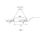
- Figure 1 depicts an imaginary scenario in which a truck V1 approaches a truck V2 from behind and is likely to wish to overtake uphill.
- a communication link is established between the vehicles, and vehicle parameters VP2 are transmitted to the first truck V1.
- the diagram also includes arrows indicating that both trucks receive location signals via GPS.
- the distance D between the vehicles is illustrated as the distance between their respective forward portions.
- the assistance system 2 is adapted to being fitted in a vehicle V1.
- the system comprises a position module 4 adapted to determining the vehicle's current location which is delivered in the form of a location signal to the vehicle's CAN (controller area network) bus.
- the system further comprises a map module 6 containing map data and adapted to delivering to the CAN bus a map signal 8 containing information which in conjunction with the location signal defines a future horizon with a predetermined length for a section of road ahead of the vehicle.
- the horizon is built up for a section of road ahead comprising small segments each about 20 metres long. Each segment comprises a gradient and an altitude but may also comprise relevant information such as bends, speed limits and road markings.
- the total length of a horizon depends on available memory capacity. When the vehicle is travelling forwards, the module will add fresh segments and delete past segments so that the total length of the horizon is always the same.
- the map module and the GPS receiver in the form of the position module are depicted in Figure 2 as separate modules but may be combined as a single module.
- the position module may be a separate module while the map module forms part of an overtaking module 14.
- the assistance system further comprises a communication module 10 adapted to identifying a vehicle V2 and to establishing with it a communication link 12 for transmitting and receiving information according to a predetermined communication protocol.
- the communication between the vehicles is preferably by an expanded version of the standard WLAN protocol IEEE 802.11 ITS (Intelligent Transport Systems) known as IEEE 802.11 p which operates within the 5.9 GHz frequency band and is dedicated to ITS.
- IEEE 802.11 p Intelligent Transport Systems
- IEEE 802.11 p Intelligent Transport Systems
- Each vehicle is provided with a transmitting and receiving unit which continually searches the surroundings for another vehicle with a similar unit. If another vehicle is detected, a two-way communication link is established between the vehicles and exchanges of information can take place.
- a typical maximum distance for establishing contact between the vehicles may be of the order of 500-600 metres.
- the assistance system comprises according to the invention an overtaking module 14 comprising a calculation unit 16 and a memory unit 18 such that the overtaking module is adapted to receiving from the CAN bus a first set of vehicle parameters VP1 for the driver's vehicle V1.
- vehicle parameters VP1 comprise at least the vehicle's total weight, speed and location and one or more parameters related to its engine power.
- the parameters related to the vehicle's engine power are available on the CAN bus as indicated by a hollow arrow from system V1 which represents inter alia the engine of vehicle V1.
- the communication module 10 is adapted to receiving from vehicle V2 a second set of vehicle parameters VP2 comprising at least the vehicle's total weight, speed and location and one or more parameters relating to its engine power, and to transmitting these vehicle parameters to said overtaking module.
- vehicle V2 be provided with a communication module 10' adapted to communicating with the communication module 10 in vehicle V1 and to transmitting the vehicle parameters VP2 via the communication link 12. It is also necessary for there to be in V2 a position module 4' and preferably a CAN bus which passes on relevant parameters from systems in V2 to the communication module 10'.
- the overtaking module 14 is adapted to determining that said vehicle V2 is a vehicle ahead. This is done by, for example, comparing the locations and directions of movement of the vehicles. Both kinds of information are obtained from the position module.
- the calculation unit 16 in the overtaking module 14 is adapted to continuously calculating the distance D between the driver's vehicle and the vehicle ahead at one or more predetermined locations for the driver's vehicle, based on the vehicle parameters VP1 and VP2.
- the distance D is therefore zero when the vehicles are side by side. As the lengths of the vehicles are known, it is easy to calculate the distance between the forward portion of the vehicle behind and the rear portion of the vehicle ahead.
- the calculated distance D is stored continuously in said memory unit 18.
- the calculation unit is further adapted to analysing how D changes over time and the overtaking module is adapted to generating overtaking instructions based on the analysis and intended for presentation to the driver of vehicle V1.
- the overtaking instructions may for example be presented via the information cluster 20, e.g. via a display.
- the distance between the vehicles calculated by the equation is that at the end of the horizon.
- the end of the horizon is as far ahead of vehicle V1 as the distance D can be calculated. It is of course possible, as discussed below, to opt to calculate the distance between the vehicles at a point ahead of vehicle V1 which is nearer than the end of the horizon, within for example the range 400-700 metres, e.g. 600 metres.
- said predetermined future location for the driver's vehicle is within the range 1.5-2 km, preferably 2 km.
- the distance between the vehicles at more than one future location, e.g. at 600 metres and 2 km.
- the calculation unit analyses the calculated distance values between the vehicles and, if the distance between them becomes zero, it determines their location at which such is the case.
- said parameter related to the vehicle's engine power is the engine's maximum power output.
- said parameter related to the vehicle's engine power is the maximum torque which the vehicle's powered wheels generate.
- the overtaking module 14 is adapted to determining that said vehicle V2 is a vehicle ahead, in which case the calculation unit in the overtaking module is adapted to continuously calculating the distance D between the driver's vehicle and the vehicle ahead at one or more predetermined future locations of the driver's vehicle, based on the vehicle parameters VP1 and VP2.
- a number of limit values indicating the distance between the vehicles after a predetermined number of metres may be set, inter alia to enable an overtaking manoeuvre to take place safely.
- limit value might be that the overtaking vehicle should be 100 metres ahead of the vehicle overtaken after two kilometres of driving from current location for the driver of vehicle V1 to be given the instructions that overtaking is feasible. Another limit value might be that if the vehicle is only 50 metres ahead of the overtaken vehicle after two kilometres of driving from current location the instruction that overtaking is not appropriate is given.
- the invention is particularly applicable in relation to driving on hills, but there are situations in driving on level roads where the invention may provide the driver with valuable information. Such a situation is where there is a change ahead in the number of traffic lanes, e.g. where two lanes merge to become a single lane one kilometre from current location.
- the present invention may also make things easier for the driver when driving downhill, e.g. if an overtaking vehicle is heavier its speed might well increase downhill.
- the assistance system may with advantage be implemented in the vehicle's computer, e.g. by means of C code.
- the main task is to calculate the speed or time required to travel the distance defined by the length of the horizon.
- the speed depends on the balance of forces which act upon the vehicle, viz. the air resistance, the friction between wheels and road, the resistance when driving uphill and the opposite downhill, and the power generated by the engine.
- There are two different ways of calculating this power either on the basis of the maximum torque which the engine can generate or on the basis of the maximum power output.
- the maximum torque which the vehicle's powered wheels generate is determined by the maximum torque which the engine generates being known and by arriving at the torque of the powered wheels by multiplying by the total gear ratio of the power train.
- An advantage of using the maximum torque is that the torque curve is relatively constantly at the speeds at which the engine most commonly runs.
- a disadvantage may be that the power on the powered wheels depends on the gear ratio, which is likely to change on steep hills, a factor which affects the calculations and has to be catered for.
- the maximum power output affords the advantage of it being the same for the whole power train apart from minor friction losses.
- the maximum power output occurs at high engine speeds, which may for example mean that on moderate climbs the propulsive force may possibly be overestimated.
- the calculations are based on a simplified vehicle model, e.g. disregarding the power train's moment of inertia which in this context is of little significance in that the vehicle's weight is dominant in high gears. Nor do the calculations take into account the losses along the power train.
- the model comprises equations for the rolling resistance, the air resistance and the resistance on hills. As mentioned above, there are two ways of calculating the propulsive force imparted by the engine.
- the force of gravity results in a perpendicular force on which the rolling resistance depends, and a force when travelling on hills, which most affects the total resistance on steep hills.
- time derivative for the amount of movement is of the nature of F eng - F air - F roll - F slope in which F eng is the propulsive force calculated on the basis of power output or torque, Fair the air resistance, F roll the rolling resistance, and Slope the resistance on hills.
- the calculation uses an algorithm which arrives at a calculated distance between two vehicles at any desired point ahead of the rear vehicle.
- the location of that point is limited by the length of the horizon which is covered by the map module and which is also used by intelligent cruise controls, which future horizon includes information about road gradients.
- the future horizon is 2 km, but according to another embodiment it is 600 metres.
- the algorithm approximates the time t1 which is determined by the mean speed during all the segments within the horizon, which is the time the driver's vehicle, vehicle V1, takes to travel from the nearest segment to the furthest segment within the horizon.
- vehicle V2 which is a known distance D P ahead of vehicle V1. This calculation starts from the segment nearest to V2 and is done for the whole of V2's horizon, resulting in a time t2 which is therefore the time which V2 needs to travel the whole horizon.
- These calculated times may be used to calculate the distance D H between vehicles V 1 and V2 at the end of the horizon.
- a fresh calculation is then done after a predetermined period of time which may be of the order of one or a few seconds.
- the algorithm thus delivers in real time a freshly estimated distance D H at the location one horizon ahead of vehicle V1.
- the equation thus calculates the distance S2 which vehicle V2 would have travelled at its mean speed during the same time as vehicle V1 has travelled. S1 is then subtracted from this distance to arrive at the distance between the vehicles if they started from the same point. Therefore the current distance between the vehicles D P is then subtracted from this distance. The distance between the vehicles therefore becomes negative when vehicle V1 is behind vehicle V2, as depicted in Figures 3 and 4 .
- the vehicle parameters VP2 required from vehicle V2 ahead are the vehicle's total weight, the vehicle's speed, the vehicle's location, and one or more parameters related to the vehicle's engine power, e.g. maximum power output or maximum torque.
- Vehicle weight is an important parameter and may inter alia be determined by input data from various systems of the vehicle, e.g. the brake system, the cruise control and other systems. It is also possible to determine the vehicle's weight by measuring the pressure on its various axles.
- Information about the engine's maximum torque is available via CAN as a reference value for other torque values for the engine which form part of this reference value.
- the engine's maximum power output may be calculated on the basis of information about its torque at the engine speed at which the engine delivers maximum power output.
- the vehicle's speed is available via CAN.
- the equation includes the current distance D P between the vehicles, which may be calculated on the basis of their locations determined by GPS measurement.
- Figure 3 depicts a simulation with the two vehicles illustrated in Figure 1 .
- the y axis denotes the distance between the vehicles in metres.
- a negative distance means that vehicle V1 is behind vehicle V2. When the vehicles are side by side, the distance between them is therefore zero.
- the x axis denotes the length of the section of road in metres.
- the vehicles travel along a 9 km section designated R with a 2 km long upgrade.
- the distance between them is represented by the curve Dp (current distance) and is initially -200 m.
- the two vehicles have the same maximum power output but differ greatly in weight.
- the vehicle ahead weighs 50 tonnes and the vehicle behind 30 tonnes.
- the vehicle behind maintains a somewhat higher speed causing the distance between the vehicles to continually decrease.
- the line designated D H1 represents the function's estimate of the distance between the vehicles 2 km ahead. For example, after about 3000 m the function estimates that the vehicles will be side by side, which is illustrated by the circle marked "1". At the circle marked "2" it may be seen that the distance then actually became 0 m after 5 km of driving. The driver of the vehicle behind may thus, even before the hill, be informed that the distance will continue to decrease uphill and that overtaking may be appropriate.
- the diagram also has a second line D H2 representing the function's estimate of the distance between the vehicles 600 metres ahead.
- the arrow marked A points at the location where the function has built up enough information to indicate the distance between the vehicles 2 km ahead of vehicle V1, i.e. when the initialisation has ended.
- Figure 4 illustrates a scenario in which the vehicle weights are reversed such that the vehicle behind is now the heavier. The same notations are used as in Figure 3 . In this case it is seen that the distance between the vehicles will instead begin to increase again when they start to climb and the driver of the vehicle behind may then dispense with commencing an overtaking manoeuvre.
Landscapes
- Engineering & Computer Science (AREA)
- Physics & Mathematics (AREA)
- Radar, Positioning & Navigation (AREA)
- Remote Sensing (AREA)
- General Physics & Mathematics (AREA)
- Electromagnetism (AREA)
- Computer Networks & Wireless Communication (AREA)
- Automation & Control Theory (AREA)
- Transportation (AREA)
- Mechanical Engineering (AREA)
- Traffic Control Systems (AREA)
Abstract
Description
- The present invention relates to an assistance system for a vehicle according to the preamble of the independent claim.
- There is constantly ongoing work to improve traffic safety, comprising inter alia use of intelligent assistance systems which make it easier for vehicle drivers to take account of the surroundings when driving. Such systems comprise inter alia cruise control systems catering for the topography of the road ahead, and lane departure warning systems which monitor the vehicle's position on the road.
- These systems are implementable both in heavy vehicles, e.g. trucks and buses, and in cars. One of the differences between driving a heavy vehicle and driving a car pertains to the ratio between the vehicle's weight and power output. A car often has a large power output surplus and is often able to maintain its desired speed even in hilly terrain, unlike a heavy vehicle which has a small power output relative to its weight. It is therefore often difficult for a truck driver to know whether it is appropriate to overtake another truck, e.g. uphill on a motorway, which might lead to an undesirable traffic situation in which the trucks block both lanes.
- There are various proposals for making things easier for the driver.
US 2008/0027607 refers to a system for making it easier to overtake which takes into account inter alia the speeds of the vehicles involved. -
EP 2,169,649 refers to an assisting system for helping a driver to plan an overtaking manoeuvre. The system takes into account the intended itinerary for the vehicle which is to be overtaken. This is communicated wirelessly between the two vehicles. - As mentioned above, it is sometimes not possible, particularly for heavy vehicles, to maintain constant speed uphill, which may result in problems in relation to overtaking. The object of the present invention is to propose an improved system which makes it easier to plan overtaking and assess whether overtaking another heavy vehicle is possible, which system is particularly suited to heavy vehicles.
- The above objects are achieved with the invention defined by the independent claim.
- Preferred embodiments are defined by the dependent claims.
- The description of the invention pertains primarily to the assistance system being provided in a heavy vehicle, e.g. a truck or a bus, but it may also be provided with advantage in a lighter vehicle, e.g. a car.
- The solution according to the invention is based on calculations which cover current vehicle speed, maximum power output or maximum torque, weight and location of both vehicles, and result in an estimate of their mean speeds at a given distance ahead. The distance comes from, for example, a so-called "look-ahead" function which expresses the topography of the road for a certain distance ahead of the vehicle, e.g. 2 km.
- The locations of the vehicles and their estimated speeds serve as a basis for calculating how far apart the vehicles will be when they have travelled the given distance. This may for example reveal that the vehicle behind will have passed the vehicle ahead by 100 m. This distance may then be used to assess whether an overtaking manoeuvre is appropriate.
- An advantage of the function according to the invention is that it provides an estimate of how far apart the vehicles will be at a given distance ahead in real time irrespective of whether the road is flat, uphill or downhill.
- The system comprises preferably a display unit adapted to indicating visually to the driver whether the system considers that an overtaking manoeuvre is or is not feasible.
-
-
Figure 1 is a schematic diagram illustrating an application of the present invention. -
Figure 2 is a block diagram illustrating the present invention. -
Figures 3 and 4 are graphs illustrating the present invention. -
Figure 1 depicts an imaginary scenario in which a truck V1 approaches a truck V2 from behind and is likely to wish to overtake uphill. According to the invention, a communication link is established between the vehicles, and vehicle parameters VP2 are transmitted to the first truck V1. The diagram also includes arrows indicating that both trucks receive location signals via GPS. The distance D between the vehicles is illustrated as the distance between their respective forward portions. - The invention will now be described in detail with reference to the block diagram in
Figure 2 . - The
assistance system 2 according to the invention is adapted to being fitted in a vehicle V1. The system comprises aposition module 4 adapted to determining the vehicle's current location which is delivered in the form of a location signal to the vehicle's CAN (controller area network) bus. The system further comprises amap module 6 containing map data and adapted to delivering to the CAN bus amap signal 8 containing information which in conjunction with the location signal defines a future horizon with a predetermined length for a section of road ahead of the vehicle. - In conjunction with information from the position module, e.g. a GPS receiver, the horizon is built up for a section of road ahead comprising small segments each about 20 metres long. Each segment comprises a gradient and an altitude but may also comprise relevant information such as bends, speed limits and road markings. The total length of a horizon depends on available memory capacity. When the vehicle is travelling forwards, the module will add fresh segments and delete past segments so that the total length of the horizon is always the same.
- According to the present invention, the map module and the GPS receiver in the form of the position module are depicted in
Figure 2 as separate modules but may be combined as a single module. Moreover, according to a variant, the position module may be a separate module while the map module forms part of anovertaking module 14. - The assistance system further comprises a
communication module 10 adapted to identifying a vehicle V2 and to establishing with it acommunication link 12 for transmitting and receiving information according to a predetermined communication protocol. The communication between the vehicles is preferably by an expanded version of the standard WLAN protocol IEEE 802.11 ITS (Intelligent Transport Systems) known as IEEE 802.11 p which operates within the 5.9 GHz frequency band and is dedicated to ITS. A substantial difference compared with ordinary WLANs is that this protocol needs no central unit for communicating, because when one node makes contact with another they will automatically establish a connection. Other protocols for communication between the vehicles are of course possible within the scope of the present invention, e.g. ordinary WLAN 802.11g, various mobile networks (e.g. GPRS, 3G, 4g) and millimetre wave communication. - Each vehicle is provided with a transmitting and receiving unit which continually searches the surroundings for another vehicle with a similar unit. If another vehicle is detected, a two-way communication link is established between the vehicles and exchanges of information can take place. A typical maximum distance for establishing contact between the vehicles may be of the order of 500-600 metres.
- The assistance system comprises according to the invention an
overtaking module 14 comprising acalculation unit 16 and amemory unit 18 such that the overtaking module is adapted to receiving from the CAN bus a first set of vehicle parameters VP1 for the driver's vehicle V1. The vehicle parameters VP1 comprise at least the vehicle's total weight, speed and location and one or more parameters related to its engine power. The parameters related to the vehicle's engine power are available on the CAN bus as indicated by a hollow arrow from system V1 which represents inter alia the engine of vehicle V1. - The
communication module 10 is adapted to receiving from vehicle V2 a second set of vehicle parameters VP2 comprising at least the vehicle's total weight, speed and location and one or more parameters relating to its engine power, and to transmitting these vehicle parameters to said overtaking module. A consequent prerequisite for the assistance system according to the invention to work is that vehicle V2 be provided with a communication module 10' adapted to communicating with thecommunication module 10 in vehicle V1 and to transmitting the vehicle parameters VP2 via thecommunication link 12. It is also necessary for there to be in V2 a position module 4' and preferably a CAN bus which passes on relevant parameters from systems in V2 to the communication module 10'. - The overtaking
module 14 is adapted to determining that said vehicle V2 is a vehicle ahead. This is done by, for example, comparing the locations and directions of movement of the vehicles. Both kinds of information are obtained from the position module. - If it is found that the vehicle V2 is a vehicle ahead, the
calculation unit 16 in theovertaking module 14 is adapted to continuously calculating the distance D between the driver's vehicle and the vehicle ahead at one or more predetermined locations for the driver's vehicle, based on the vehicle parameters VP1 and VP2. - The distance D is therefore zero when the vehicles are side by side. As the lengths of the vehicles are known, it is easy to calculate the distance between the forward portion of the vehicle behind and the rear portion of the vehicle ahead.
- The calculated distance D is stored continuously in said
memory unit 18. The calculation unit is further adapted to analysing how D changes over time and the overtaking module is adapted to generating overtaking instructions based on the analysis and intended for presentation to the driver of vehicle V1. The overtaking instructions may for example be presented via theinformation cluster 20, e.g. via a display. - The assistance system according to the invention is used to calculate the distance DH between the vehicles one horizon ahead of vehicle V1 by the equation

in which
DH is the distance between the vehicles at the end of the horizon,
Dp the current distance between the vehicles,
S1 the distance travelled by vehicle V1 during time t1, and
S2 the distance travelled by vehicle V2 during time t2. - The equation is explained in detail below.
- The distance between the vehicles calculated by the equation is that at the end of the horizon. The end of the horizon is as far ahead of vehicle V1 as the distance D can be calculated. It is of course possible, as discussed below, to opt to calculate the distance between the vehicles at a point ahead of vehicle V1 which is nearer than the end of the horizon, within for example the range 400-700 metres, e.g. 600 metres.
- According to a preferred embodiment, said predetermined future location for the driver's vehicle is within the range 1.5-2 km, preferably 2 km.
- According to a further embodiment, it is of course possible to opt to calculate the distance between the vehicles at more than one future location, e.g. at 600 metres and 2 km.
- According to a preferred embodiment, the calculation unit analyses the calculated distance values between the vehicles and, if the distance between them becomes zero, it determines their location at which such is the case.
- According to an embodiment, said parameter related to the vehicle's engine power is the engine's maximum power output.
- According to another embodiment, said parameter related to the vehicle's engine power is the maximum torque which the vehicle's powered wheels generate.
- These two embodiments are explained further on.
- The overtaking
module 14 is adapted to determining that said vehicle V2 is a vehicle ahead, in which case the calculation unit in the overtaking module is adapted to continuously calculating the distance D between the driver's vehicle and the vehicle ahead at one or more predetermined future locations of the driver's vehicle, based on the vehicle parameters VP1 and VP2. - A number of limit values indicating the distance between the vehicles after a predetermined number of metres may be set, inter alia to enable an overtaking manoeuvre to take place safely.
- An example of a limit value might be that the overtaking vehicle should be 100 metres ahead of the vehicle overtaken after two kilometres of driving from current location for the driver of vehicle V1 to be given the instructions that overtaking is feasible. Another limit value might be that if the vehicle is only 50 metres ahead of the overtaken vehicle after two kilometres of driving from current location the instruction that overtaking is not appropriate is given.
- The invention is particularly applicable in relation to driving on hills, but there are situations in driving on level roads where the invention may provide the driver with valuable information. Such a situation is where there is a change ahead in the number of traffic lanes, e.g. where two lanes merge to become a single lane one kilometre from current location.
- The present invention may also make things easier for the driver when driving downhill, e.g. if an overtaking vehicle is heavier its speed might well increase downhill.
- The assistance system may with advantage be implemented in the vehicle's computer, e.g. by means of C code.
- The main task is to calculate the speed or time required to travel the distance defined by the length of the horizon. The speed depends on the balance of forces which act upon the vehicle, viz. the air resistance, the friction between wheels and road, the resistance when driving uphill and the opposite downhill, and the power generated by the engine. There are two different ways of calculating this power, either on the basis of the maximum torque which the engine can generate or on the basis of the maximum power output.
- The maximum torque which the vehicle's powered wheels generate is determined by the maximum torque which the engine generates being known and by arriving at the torque of the powered wheels by multiplying by the total gear ratio of the power train. An advantage of using the maximum torque is that the torque curve is relatively constantly at the speeds at which the engine most commonly runs. A disadvantage may be that the power on the powered wheels depends on the gear ratio, which is likely to change on steep hills, a factor which affects the calculations and has to be catered for.
- Using instead the maximum power output affords the advantage of it being the same for the whole power train apart from minor friction losses. The maximum power output occurs at high engine speeds, which may for example mean that on moderate climbs the propulsive force may possibly be overestimated.
- The calculations are based on a simplified vehicle model, e.g. disregarding the power train's moment of inertia which in this context is of little significance in that the vehicle's weight is dominant in high gears. Nor do the calculations take into account the losses along the power train.
- The model comprises equations for the rolling resistance, the air resistance and the resistance on hills. As mentioned above, there are two ways of calculating the propulsive force imparted by the engine.
- The force of gravity results in a perpendicular force on which the rolling resistance depends, and a force when travelling on hills, which most affects the total resistance on steep hills.
- To sum up, this means that the time derivative for the amount of movement is of the nature of

in which
Feng is the propulsive force calculated on the basis of power output or torque,
Fair the air resistance,
Froll the rolling resistance, and
Slope the resistance on hills. - As this relationship is time-dependent, the speed of a vehicle at the beginning and end of a horizon of known length can be calculated.
- Calculating the distance between the vehicles will now be described in detail. The calculation uses an algorithm which arrives at a calculated distance between two vehicles at any desired point ahead of the rear vehicle. The location of that point is limited by the length of the horizon which is covered by the map module and which is also used by intelligent cruise controls, which future horizon includes information about road gradients. According to an embodiment the future horizon is 2 km, but according to another embodiment it is 600 metres.
- The algorithm approximates the time t1 which is determined by the mean speed during all the segments within the horizon, which is the time the driver's vehicle, vehicle V1, takes to travel from the nearest segment to the furthest segment within the horizon. The same calculation is done for the vehicle ahead, vehicle V2, which is a known distance DP ahead of vehicle V1. This calculation starts from the segment nearest to V2 and is done for the whole of V2's horizon, resulting in a time t2 which is therefore the time which V2 needs to travel the whole horizon.
- These calculated times may be used to calculate the distance DH between vehicles V 1 and V2 at the end of the horizon. A fresh calculation is then done after a predetermined period of time which may be of the order of one or a few seconds. The algorithm thus delivers in real time a freshly estimated distance DH at the location one horizon ahead of vehicle V1.
- The distance DH between the vehicles one horizon ahead of vehicle V1 is calculated by the equation

in which
DH is the distance between the vehicles at the end of the horizon,
DP the current distance between the vehicles,
S1 the distance travelled by vehicle V1 during time t1, and
S2 the distance travelled by vehicle V2 during time t2. - The equation thus calculates the distance S2 which vehicle V2 would have travelled at its mean speed during the same time as vehicle V1 has travelled. S1 is then subtracted from this distance to arrive at the distance between the vehicles if they started from the same point. Therefore the current distance between the vehicles DP is then subtracted from this distance. The distance between the vehicles therefore becomes negative when vehicle V1 is behind vehicle V2, as depicted in
Figures 3 and 4 . - The vehicle parameters VP2 required from vehicle V2 ahead are
the vehicle's total weight,
the vehicle's speed,
the vehicle's location, and
one or more parameters related to the vehicle's engine power, e.g. maximum power output or maximum torque. - Vehicle weight is an important parameter and may inter alia be determined by input data from various systems of the vehicle, e.g. the brake system, the cruise control and other systems. It is also possible to determine the vehicle's weight by measuring the pressure on its various axles.
- Information about the engine's maximum torque is available via CAN as a reference value for other torque values for the engine which form part of this reference value.
- The engine's maximum power output may be calculated on the basis of information about its torque at the engine speed at which the engine delivers maximum power output.
- The vehicle's speed is available via CAN.
- The equation includes the current distance DP between the vehicles, which may be calculated on the basis of their locations determined by GPS measurement.
-
Figure 3 depicts a simulation with the two vehicles illustrated inFigure 1 . - The y axis denotes the distance between the vehicles in metres. A negative distance means that vehicle V1 is behind vehicle V2. When the vehicles are side by side, the distance between them is therefore zero. The x axis denotes the length of the section of road in metres.
- The vehicles travel along a 9 km section designated R with a 2 km long upgrade.
- The distance between them is represented by the curve Dp (current distance) and is initially -200 m.
- The two vehicles have the same maximum power output but differ greatly in weight. The vehicle ahead weighs 50 tonnes and the vehicle behind 30 tonnes. The vehicle behind maintains a somewhat higher speed causing the distance between the vehicles to continually decrease. The line designated DH1 represents the function's estimate of the distance between the
vehicles 2 km ahead. For example, after about 3000 m the function estimates that the vehicles will be side by side, which is illustrated by the circle marked "1". At the circle marked "2" it may be seen that the distance then actually became 0 m after 5 km of driving. The driver of the vehicle behind may thus, even before the hill, be informed that the distance will continue to decrease uphill and that overtaking may be appropriate. - The diagram also has a second line DH2 representing the function's estimate of the distance between the vehicles 600 metres ahead.
- The arrow marked A points at the location where the function has built up enough information to indicate the distance between the
vehicles 2 km ahead of vehicle V1, i.e. when the initialisation has ended. -
Figure 4 illustrates a scenario in which the vehicle weights are reversed such that the vehicle behind is now the heavier. The same notations are used as inFigure 3 . In this case it is seen that the distance between the vehicles will instead begin to increase again when they start to climb and the driver of the vehicle behind may then dispense with commencing an overtaking manoeuvre. - The present invention is not restricted to the preferred embodiments described above. Sundry alternatives, modifications and equivalents may be used. The embodiments described above are therefore not to be regarded as limiting the invention's protective scope which is defined by the attached claims.
-
- 2
- assistance system
- 4
- position module
- 6
- map module
- 8
- map signal
- 10
- communication module
- 12
- communication link
- 14
- overtaking module
- 16
- calculation unit
- 18
- memory unit
- 20
- instrument cluster
Claims (10)
- An assistance system (2) situated in a vehicle V1, which system comprises a position module (4) adapted to determining the vehicle's current location,
a map module (6) containing map data and adapted to delivering a map signal (8) comprising information which defines a future horizon with a predetermined length for a future section of road for the vehicle, and
a communication module (10) adapted to identifying a vehicle V2 and to establishing a communication link (12) with said vehicle for transmitting and receiving information according to a predetermined communication protocol,
characterised in that the assistance system further comprises an overtaking module (14) comprising a calculation unit (16) and a memory unit (18) and adapted to receiving a first set of vehicle parameters VP1 for the driver's vehicle V1, which parameters comprise at least the vehicle's total weight, speed and location and one or more parameters related to its engine power,
the communication module (10) is adapted to receiving from vehicle V2 a second set of vehicle parameters VP2 which comprise at least the vehicle's total weight, speed and location and one or more parameters related to its engine power, and to conveying these vehicle parameters to said overtaking module,
the overtaking module (14) is adapted to determining that said vehicle V2 is a vehicle ahead, in which case the calculation unit (16) in the overtaking module is adapted to continuously calculating the distance D between the driver's vehicle and the vehicle ahead at one or more predetermined future locations for the driver's vehicle, based on the vehicle parameters VP1 and VP2,
the calculated distances D are stored continuously in said memory unit (18),
the calculation unit (16) is further adapted to analysing how D changes,
and the overtaking module (14) is adapted to generating overtaking instructions based on the analysis and intended to be presented to the driver of vehicle V1. - An assistance system according to claim 1, in which the distance DH between the vehicles one horizon ahead of vehicle V1 is calculated by the equation

DH is the distance between the vehicles at the end of the horizon,
DP the current distance between the vehicles,
S 1 the distance travelled by vehicle V 1 during time t1, and
S2 the distance travelled by vehicle V2 during time t2. - An assistance system according to claim 1 or 2, in which said analysis establishes whether the distance between the vehicles becomes zero, in which case the analysis determines the location for the vehicles where this occurs.
- An assistance system according to any one of claims 1-3, in which said parameter related to the vehicle's engine power is the engine's maximum power output.
- An assistance system according to any one of claims 1-3, in which said parameter related to the vehicle's engine power is the maximum torque which its powered wheels generate.
- An assistance system according to any one of claims 1-5, in which said map data comprise information about road gradients, changes in the traffic lane divisions, and speed limit changes.
- An assistance system according to any one of claims 1-6, in which said predetermined future location for the driver's vehicle is within the range 400-700 metres, preferably 600 metres.
- An assistance system according to any one of claims 1-6, in which said predetermined future location for the driver's vehicle is within the range 1.5-2 km, preferably 2 km.
- An assistance system according to any one of claims 1-6, in which said predetermined future locations for the driver's vehicle are 600 m and 2 km.
- An assistance system according to claims 1-9, in which said predetermined communication protocol is WLAN according to IEEE 802.11p.
Applications Claiming Priority (1)
| Application Number | Priority Date | Filing Date | Title |
|---|---|---|---|
| SE1050999A SE535194C2 (en) | 2010-09-28 | 2010-09-28 | Assistance system for a vehicle to generate overtaking instructions |
Publications (2)
| Publication Number | Publication Date |
|---|---|
| EP2434468A1 true EP2434468A1 (en) | 2012-03-28 |
| EP2434468B1 EP2434468B1 (en) | 2016-07-06 |
Family
ID=45044306
Family Applications (1)
| Application Number | Title | Priority Date | Filing Date |
|---|---|---|---|
| EP11182120.3A Active EP2434468B1 (en) | 2010-09-28 | 2011-09-21 | Assistance system for a vehicle to generate overtaking instructions |
Country Status (3)
| Country | Link |
|---|---|
| EP (1) | EP2434468B1 (en) |
| BR (1) | BRPI1104592A2 (en) |
| SE (1) | SE535194C2 (en) |
Cited By (3)
| Publication number | Priority date | Publication date | Assignee | Title |
|---|---|---|---|---|
| WO2014168557A1 (en) * | 2013-04-08 | 2014-10-16 | Scania Cv Ab | Overtaking adviser |
| DE102017104592A1 (en) | 2017-03-06 | 2018-09-06 | Saf-Holland Gmbh | System to support a safe overhaul process |
| US10762718B2 (en) | 2017-02-17 | 2020-09-01 | Fca Us Llc | System and method for determining minimal negative distance between two objects |
Citations (3)
| Publication number | Priority date | Publication date | Assignee | Title |
|---|---|---|---|---|
| WO2006037360A1 (en) * | 2004-10-05 | 2006-04-13 | Bayerische Motoren Werke Aktiengesellschaft | Driver information system for information on the possibility of carrying out overtaking manoeuvres |
| US20080027607A1 (en) | 2004-04-21 | 2008-01-31 | Siemens Aktiengesellschaft | Assistance System for Motor Vehicles |
| EP2169649A1 (en) | 2008-09-24 | 2010-03-31 | Robert Bosch GmbH | Method for providing a recommendation for carrying out an overtaking manoeuvre |
-
2010
- 2010-09-28 SE SE1050999A patent/SE535194C2/en unknown
-
2011
- 2011-09-21 EP EP11182120.3A patent/EP2434468B1/en active Active
- 2011-09-21 BR BRPI1104592-2A patent/BRPI1104592A2/en active Search and Examination
Patent Citations (3)
| Publication number | Priority date | Publication date | Assignee | Title |
|---|---|---|---|---|
| US20080027607A1 (en) | 2004-04-21 | 2008-01-31 | Siemens Aktiengesellschaft | Assistance System for Motor Vehicles |
| WO2006037360A1 (en) * | 2004-10-05 | 2006-04-13 | Bayerische Motoren Werke Aktiengesellschaft | Driver information system for information on the possibility of carrying out overtaking manoeuvres |
| EP2169649A1 (en) | 2008-09-24 | 2010-03-31 | Robert Bosch GmbH | Method for providing a recommendation for carrying out an overtaking manoeuvre |
Non-Patent Citations (1)
| Title |
|---|
| TECHNICAL COMMITTEE: "Car 2 Car Communication Consortium Manifesto - Overview of the C2C-CC System", 28 August 2007 (2007-08-28), pages 1 - 94, XP002665680, Retrieved from the Internet <URL:http://elib.dlr.de/48380/1/C2C-CC_manifesto_v1.1.pdf> [retrieved on 20111209] * |
Cited By (4)
| Publication number | Priority date | Publication date | Assignee | Title |
|---|---|---|---|---|
| WO2014168557A1 (en) * | 2013-04-08 | 2014-10-16 | Scania Cv Ab | Overtaking adviser |
| US10762718B2 (en) | 2017-02-17 | 2020-09-01 | Fca Us Llc | System and method for determining minimal negative distance between two objects |
| DE102017104592A1 (en) | 2017-03-06 | 2018-09-06 | Saf-Holland Gmbh | System to support a safe overhaul process |
| DE102017104592B4 (en) * | 2017-03-06 | 2020-10-08 | Saf-Holland Gmbh | System to support a safe overhaul process |
Also Published As
| Publication number | Publication date |
|---|---|
| SE535194C2 (en) | 2012-05-15 |
| SE1050999A1 (en) | 2012-03-29 |
| EP2434468B1 (en) | 2016-07-06 |
| BRPI1104592A2 (en) | 2015-05-19 |
Similar Documents
| Publication | Publication Date | Title |
|---|---|---|
| EP3052356B1 (en) | System and method for controlling a vehicle platoon with a common position-based driving strategy | |
| EP3098574B1 (en) | Device for determining a fuel consumption behavior | |
| EP3118079B1 (en) | Road surface submergence estimation device | |
| JP4466718B2 (en) | Traveling locus generation method and traveling locus generation device | |
| JP4918076B2 (en) | Hybrid vehicle control device and hybrid vehicle | |
| EP3052355B1 (en) | A system and a method for vehicle platoons comprising at least two vehicles. | |
| US20230019462A1 (en) | MPC-Based Trajectory Tracking of a First Vehicle Using Trajectory Information on a Second Vehicle | |
| WO2015047179A1 (en) | Control unit and method to control a vehicle in a vehicle platoon based on the predicted behaviour of the preceeding vehicle | |
| SE538766C2 (en) | Method and control unit in a central node for determining a velocity profile for each vehicle comprised in a platoon of grouped vehicles | |
| US20190225218A1 (en) | Vehicle control apparatus | |
| US12030491B2 (en) | Ascertaining a trajectory for a first vehicle while taking into consideration the drive behavior of a second vehicle | |
| JP2019098914A (en) | Pre-congestion deceleration notification apparatus | |
| US20200398810A1 (en) | Predictive grade optimization in cruise control | |
| EP3145777A1 (en) | Method and system for improving the operating efficiency of a vehicle during driving of a vehicle along a route of travel | |
| EP3145781A1 (en) | Method and system for adapting the acceleration of a vehicle during driving of the vehicle along a route of travel | |
| JPH10261194A (en) | Vehicle group formation control device and method | |
| EP2434468B1 (en) | Assistance system for a vehicle to generate overtaking instructions | |
| SE538817C2 (en) | A method and a control unit for determining a set of velocity profiles for a platoon of grouped vehicles | |
| EP3871058B1 (en) | A method for controlling a platoon of vehicles | |
| EP3145778B1 (en) | Method and system for adapting the velocity of a vehicle during driving of the vehicle along a route of travel | |
| JP3451148B2 (en) | Car navigation system | |
| DE102016003433B4 (en) | Method and control unit for determining a speed profile | |
| D'Amato et al. | Development and on-board testing of an ADAS-based methodology to enhance cruise control features towards CO2 reduction | |
| CN113246949B (en) | Cruise control method for automatically following distance | |
| JP2001344686A (en) | Platoon running control device |
Legal Events
| Date | Code | Title | Description |
|---|---|---|---|
| PUAI | Public reference made under article 153(3) epc to a published international application that has entered the european phase |
Free format text: ORIGINAL CODE: 0009012 |
|
| AK | Designated contracting states |
Kind code of ref document: A1 Designated state(s): AL AT BE BG CH CY CZ DE DK EE ES FI FR GB GR HR HU IE IS IT LI LT LU LV MC MK MT NL NO PL PT RO RS SE SI SK SM TR |
|
| AX | Request for extension of the european patent |
Extension state: BA ME |
|
| RIN1 | Information on inventor provided before grant (corrected) |
Inventor name: BACKLUND, TOMAS |
|
| 17P | Request for examination filed |
Effective date: 20120928 |
|
| GRAP | Despatch of communication of intention to grant a patent |
Free format text: ORIGINAL CODE: EPIDOSNIGR1 |
|
| INTG | Intention to grant announced |
Effective date: 20160225 |
|
| GRAS | Grant fee paid |
Free format text: ORIGINAL CODE: EPIDOSNIGR3 |
|
| GRAA | (expected) grant |
Free format text: ORIGINAL CODE: 0009210 |
|
| AK | Designated contracting states |
Kind code of ref document: B1 Designated state(s): AL AT BE BG CH CY CZ DE DK EE ES FI FR GB GR HR HU IE IS IT LI LT LU LV MC MK MT NL NO PL PT RO RS SE SI SK SM TR |
|
| REG | Reference to a national code |
Ref country code: GB Ref legal event code: FG4D |
|
| REG | Reference to a national code |
Ref country code: AT Ref legal event code: REF Ref document number: 811196 Country of ref document: AT Kind code of ref document: T Effective date: 20160715 Ref country code: CH Ref legal event code: EP |
|
| REG | Reference to a national code |
Ref country code: IE Ref legal event code: FG4D |
|
| REG | Reference to a national code |
Ref country code: DE Ref legal event code: R096 Ref document number: 602011027887 Country of ref document: DE |
|
| REG | Reference to a national code |
Ref country code: FR Ref legal event code: PLFP Year of fee payment: 6 |
|
| REG | Reference to a national code |
Ref country code: NL Ref legal event code: MP Effective date: 20160706 |
|
| REG | Reference to a national code |
Ref country code: LT Ref legal event code: MG4D |
|
| REG | Reference to a national code |
Ref country code: AT Ref legal event code: MK05 Ref document number: 811196 Country of ref document: AT Kind code of ref document: T Effective date: 20160706 |
|
| PG25 | Lapsed in a contracting state [announced via postgrant information from national office to epo] |
Ref country code: NO Free format text: LAPSE BECAUSE OF FAILURE TO SUBMIT A TRANSLATION OF THE DESCRIPTION OR TO PAY THE FEE WITHIN THE PRESCRIBED TIME-LIMIT Effective date: 20161006 Ref country code: IT Free format text: LAPSE BECAUSE OF FAILURE TO SUBMIT A TRANSLATION OF THE DESCRIPTION OR TO PAY THE FEE WITHIN THE PRESCRIBED TIME-LIMIT Effective date: 20160706 Ref country code: RS Free format text: LAPSE BECAUSE OF FAILURE TO SUBMIT A TRANSLATION OF THE DESCRIPTION OR TO PAY THE FEE WITHIN THE PRESCRIBED TIME-LIMIT Effective date: 20160706 Ref country code: NL Free format text: LAPSE BECAUSE OF FAILURE TO SUBMIT A TRANSLATION OF THE DESCRIPTION OR TO PAY THE FEE WITHIN THE PRESCRIBED TIME-LIMIT Effective date: 20160706 Ref country code: IS Free format text: LAPSE BECAUSE OF FAILURE TO SUBMIT A TRANSLATION OF THE DESCRIPTION OR TO PAY THE FEE WITHIN THE PRESCRIBED TIME-LIMIT Effective date: 20161106 Ref country code: LT Free format text: LAPSE BECAUSE OF FAILURE TO SUBMIT A TRANSLATION OF THE DESCRIPTION OR TO PAY THE FEE WITHIN THE PRESCRIBED TIME-LIMIT Effective date: 20160706 Ref country code: HR Free format text: LAPSE BECAUSE OF FAILURE TO SUBMIT A TRANSLATION OF THE DESCRIPTION OR TO PAY THE FEE WITHIN THE PRESCRIBED TIME-LIMIT Effective date: 20160706 Ref country code: FI Free format text: LAPSE BECAUSE OF FAILURE TO SUBMIT A TRANSLATION OF THE DESCRIPTION OR TO PAY THE FEE WITHIN THE PRESCRIBED TIME-LIMIT Effective date: 20160706 |
|
| PG25 | Lapsed in a contracting state [announced via postgrant information from national office to epo] |
Ref country code: LV Free format text: LAPSE BECAUSE OF FAILURE TO SUBMIT A TRANSLATION OF THE DESCRIPTION OR TO PAY THE FEE WITHIN THE PRESCRIBED TIME-LIMIT Effective date: 20160706 Ref country code: AT Free format text: LAPSE BECAUSE OF FAILURE TO SUBMIT A TRANSLATION OF THE DESCRIPTION OR TO PAY THE FEE WITHIN THE PRESCRIBED TIME-LIMIT Effective date: 20160706 Ref country code: BE Free format text: LAPSE BECAUSE OF NON-PAYMENT OF DUE FEES Effective date: 20160706 Ref country code: GR Free format text: LAPSE BECAUSE OF FAILURE TO SUBMIT A TRANSLATION OF THE DESCRIPTION OR TO PAY THE FEE WITHIN THE PRESCRIBED TIME-LIMIT Effective date: 20161007 Ref country code: SE Free format text: LAPSE BECAUSE OF FAILURE TO SUBMIT A TRANSLATION OF THE DESCRIPTION OR TO PAY THE FEE WITHIN THE PRESCRIBED TIME-LIMIT Effective date: 20160706 Ref country code: PL Free format text: LAPSE BECAUSE OF FAILURE TO SUBMIT A TRANSLATION OF THE DESCRIPTION OR TO PAY THE FEE WITHIN THE PRESCRIBED TIME-LIMIT Effective date: 20160706 Ref country code: ES Free format text: LAPSE BECAUSE OF FAILURE TO SUBMIT A TRANSLATION OF THE DESCRIPTION OR TO PAY THE FEE WITHIN THE PRESCRIBED TIME-LIMIT Effective date: 20160706 Ref country code: PT Free format text: LAPSE BECAUSE OF FAILURE TO SUBMIT A TRANSLATION OF THE DESCRIPTION OR TO PAY THE FEE WITHIN THE PRESCRIBED TIME-LIMIT Effective date: 20161107 |
|
| REG | Reference to a national code |
Ref country code: DE Ref legal event code: R097 Ref document number: 602011027887 Country of ref document: DE |
|
| PG25 | Lapsed in a contracting state [announced via postgrant information from national office to epo] |
Ref country code: MC Free format text: LAPSE BECAUSE OF FAILURE TO SUBMIT A TRANSLATION OF THE DESCRIPTION OR TO PAY THE FEE WITHIN THE PRESCRIBED TIME-LIMIT Effective date: 20160706 Ref country code: RO Free format text: LAPSE BECAUSE OF FAILURE TO SUBMIT A TRANSLATION OF THE DESCRIPTION OR TO PAY THE FEE WITHIN THE PRESCRIBED TIME-LIMIT Effective date: 20160706 Ref country code: EE Free format text: LAPSE BECAUSE OF FAILURE TO SUBMIT A TRANSLATION OF THE DESCRIPTION OR TO PAY THE FEE WITHIN THE PRESCRIBED TIME-LIMIT Effective date: 20160706 |
|
| REG | Reference to a national code |
Ref country code: CH Ref legal event code: PL |
|
| PLBE | No opposition filed within time limit |
Free format text: ORIGINAL CODE: 0009261 |
|
| STAA | Information on the status of an ep patent application or granted ep patent |
Free format text: STATUS: NO OPPOSITION FILED WITHIN TIME LIMIT |
|
| PG25 | Lapsed in a contracting state [announced via postgrant information from national office to epo] |
Ref country code: BG Free format text: LAPSE BECAUSE OF FAILURE TO SUBMIT A TRANSLATION OF THE DESCRIPTION OR TO PAY THE FEE WITHIN THE PRESCRIBED TIME-LIMIT Effective date: 20161006 Ref country code: SK Free format text: LAPSE BECAUSE OF FAILURE TO SUBMIT A TRANSLATION OF THE DESCRIPTION OR TO PAY THE FEE WITHIN THE PRESCRIBED TIME-LIMIT Effective date: 20160706 Ref country code: DK Free format text: LAPSE BECAUSE OF FAILURE TO SUBMIT A TRANSLATION OF THE DESCRIPTION OR TO PAY THE FEE WITHIN THE PRESCRIBED TIME-LIMIT Effective date: 20160706 Ref country code: CZ Free format text: LAPSE BECAUSE OF FAILURE TO SUBMIT A TRANSLATION OF THE DESCRIPTION OR TO PAY THE FEE WITHIN THE PRESCRIBED TIME-LIMIT Effective date: 20160706 Ref country code: SM Free format text: LAPSE BECAUSE OF FAILURE TO SUBMIT A TRANSLATION OF THE DESCRIPTION OR TO PAY THE FEE WITHIN THE PRESCRIBED TIME-LIMIT Effective date: 20160706 |
|
| 26N | No opposition filed |
Effective date: 20170407 |
|
| REG | Reference to a national code |
Ref country code: IE Ref legal event code: MM4A |
|
| PG25 | Lapsed in a contracting state [announced via postgrant information from national office to epo] |
Ref country code: LI Free format text: LAPSE BECAUSE OF NON-PAYMENT OF DUE FEES Effective date: 20160930 Ref country code: IE Free format text: LAPSE BECAUSE OF NON-PAYMENT OF DUE FEES Effective date: 20160921 Ref country code: CH Free format text: LAPSE BECAUSE OF NON-PAYMENT OF DUE FEES Effective date: 20160930 |
|
| REG | Reference to a national code |
Ref country code: FR Ref legal event code: PLFP Year of fee payment: 7 |
|
| PG25 | Lapsed in a contracting state [announced via postgrant information from national office to epo] |
Ref country code: LU Free format text: LAPSE BECAUSE OF NON-PAYMENT OF DUE FEES Effective date: 20160921 Ref country code: SI Free format text: LAPSE BECAUSE OF FAILURE TO SUBMIT A TRANSLATION OF THE DESCRIPTION OR TO PAY THE FEE WITHIN THE PRESCRIBED TIME-LIMIT Effective date: 20160706 |
|
| PG25 | Lapsed in a contracting state [announced via postgrant information from national office to epo] |
Ref country code: CY Free format text: LAPSE BECAUSE OF FAILURE TO SUBMIT A TRANSLATION OF THE DESCRIPTION OR TO PAY THE FEE WITHIN THE PRESCRIBED TIME-LIMIT Effective date: 20160706 Ref country code: HU Free format text: LAPSE BECAUSE OF FAILURE TO SUBMIT A TRANSLATION OF THE DESCRIPTION OR TO PAY THE FEE WITHIN THE PRESCRIBED TIME-LIMIT; INVALID AB INITIO Effective date: 20110921 |
|
| PG25 | Lapsed in a contracting state [announced via postgrant information from national office to epo] |
Ref country code: TR Free format text: LAPSE BECAUSE OF FAILURE TO SUBMIT A TRANSLATION OF THE DESCRIPTION OR TO PAY THE FEE WITHIN THE PRESCRIBED TIME-LIMIT Effective date: 20160706 Ref country code: MT Free format text: LAPSE BECAUSE OF NON-PAYMENT OF DUE FEES Effective date: 20160930 Ref country code: MK Free format text: LAPSE BECAUSE OF FAILURE TO SUBMIT A TRANSLATION OF THE DESCRIPTION OR TO PAY THE FEE WITHIN THE PRESCRIBED TIME-LIMIT Effective date: 20160706 |
|
| REG | Reference to a national code |
Ref country code: FR Ref legal event code: PLFP Year of fee payment: 8 |
|
| PG25 | Lapsed in a contracting state [announced via postgrant information from national office to epo] |
Ref country code: AL Free format text: LAPSE BECAUSE OF FAILURE TO SUBMIT A TRANSLATION OF THE DESCRIPTION OR TO PAY THE FEE WITHIN THE PRESCRIBED TIME-LIMIT Effective date: 20160706 |
|
| P01 | Opt-out of the competence of the unified patent court (upc) registered |
Effective date: 20230518 |
|
| PGFP | Annual fee paid to national office [announced via postgrant information from national office to epo] |
Ref country code: DE Payment date: 20250730 Year of fee payment: 15 |
|
| PGFP | Annual fee paid to national office [announced via postgrant information from national office to epo] |
Ref country code: GB Payment date: 20250731 Year of fee payment: 15 |
|
| PGFP | Annual fee paid to national office [announced via postgrant information from national office to epo] |
Ref country code: FR Payment date: 20250808 Year of fee payment: 15 |