EP2434254A1 - Stock thickness anomaly detection device - Google Patents
Stock thickness anomaly detection device Download PDFInfo
- Publication number
- EP2434254A1 EP2434254A1 EP11182377A EP11182377A EP2434254A1 EP 2434254 A1 EP2434254 A1 EP 2434254A1 EP 11182377 A EP11182377 A EP 11182377A EP 11182377 A EP11182377 A EP 11182377A EP 2434254 A1 EP2434254 A1 EP 2434254A1
- Authority
- EP
- European Patent Office
- Prior art keywords
- photoeye
- mask
- slot
- detection device
- stock
- Prior art date
- Legal status (The legal status is an assumption and is not a legal conclusion. Google has not performed a legal analysis and makes no representation as to the accuracy of the status listed.)
- Granted
Links
- 238000001514 detection method Methods 0.000 title claims abstract description 41
- 230000003287 optical effect Effects 0.000 claims abstract description 16
- 230000000903 blocking effect Effects 0.000 claims description 15
- 238000002360 preparation method Methods 0.000 description 4
- 230000035945 sensitivity Effects 0.000 description 3
- 230000009977 dual effect Effects 0.000 description 2
- 230000003321 amplification Effects 0.000 description 1
- 239000006227 byproduct Substances 0.000 description 1
- 230000001419 dependent effect Effects 0.000 description 1
- 238000004519 manufacturing process Methods 0.000 description 1
- 239000000463 material Substances 0.000 description 1
- 238000000034 method Methods 0.000 description 1
- 230000004048 modification Effects 0.000 description 1
- 238000012986 modification Methods 0.000 description 1
- 238000003199 nucleic acid amplification method Methods 0.000 description 1
- 238000004513 sizing Methods 0.000 description 1
Images







Classifications
-
- B—PERFORMING OPERATIONS; TRANSPORTING
- B29—WORKING OF PLASTICS; WORKING OF SUBSTANCES IN A PLASTIC STATE IN GENERAL
- B29D—PRODUCING PARTICULAR ARTICLES FROM PLASTICS OR FROM SUBSTANCES IN A PLASTIC STATE
- B29D30/00—Producing pneumatic or solid tyres or parts thereof
- B29D30/0061—Accessories, details or auxiliary operations not otherwise provided for
-
- G—PHYSICS
- G01—MEASURING; TESTING
- G01B—MEASURING LENGTH, THICKNESS OR SIMILAR LINEAR DIMENSIONS; MEASURING ANGLES; MEASURING AREAS; MEASURING IRREGULARITIES OF SURFACES OR CONTOURS
- G01B11/00—Measuring arrangements characterised by the use of optical techniques
- G01B11/02—Measuring arrangements characterised by the use of optical techniques for measuring length, width or thickness
- G01B11/06—Measuring arrangements characterised by the use of optical techniques for measuring length, width or thickness for measuring thickness ; e.g. of sheet material
- G01B11/0691—Measuring arrangements characterised by the use of optical techniques for measuring length, width or thickness for measuring thickness ; e.g. of sheet material of objects while moving
-
- B—PERFORMING OPERATIONS; TRANSPORTING
- B29—WORKING OF PLASTICS; WORKING OF SUBSTANCES IN A PLASTIC STATE IN GENERAL
- B29D—PRODUCING PARTICULAR ARTICLES FROM PLASTICS OR FROM SUBSTANCES IN A PLASTIC STATE
- B29D30/00—Producing pneumatic or solid tyres or parts thereof
- B29D30/0061—Accessories, details or auxiliary operations not otherwise provided for
- B29D2030/0066—Tyre quality control during manufacturing
Definitions
- the invention relates generally to splice detection devices for use in tire building manufacturing lines and, more particular, to splice detection devices that detect overlap splices in stock prior to being wound onto a tire.
- Overlap splices are a by-product of a non-continuous stock preparation process and are common in conventional tire building.
- Two notable examples are ply stock and spiral overlay stock when it is wound on large spools. Both have lapped splices built in during the stock preparation process to form a continuous strip or sheet. The splices also hold the strip or sheet together during the tire building process. Since they create a discontinuity in the tire, these double-thick splices may prove undesirable and may be unacceptable in a tire.
- the invention relates to a device in accordance with claim 1.
- a detection device detects a thickness anomaly region within a strip of stock and includes a first roller operatively rotating as the strip of stock passes over a first roller surface; a pivotally mounted pinch roller positioned to operatively pivot about a pivot axis against the strip of stock passing over the first roller; a photoeye mask positioned to rotate about the pivot axis responsive to pivotal movement of the pinch roller; a photoeye slot within the photoeye mask extending between a slot leading end and a slot trailing end; and the transmitting and receiving optical devices positioned on opposite sides of the photoeye slot of the photoeye mask and operative in an photoeye mask-aligned position to project a centered through-beam through the photoeye slot between the transmitting and receiving optical devices.
- the through-beam is blocked by the photoeye mask as the photoeye mask operatively rotates a preset deflection angle out of the photoeye mask-aligned position and into a photoeye mask blocking position.
- the preset deflection angle required to rotate the photoeye mask between the photoeye mask-aligned and photoeye mask blocking positions is adjustable.
- the photoeye mask slot preferably tapers in width between the leading and trailing ends.
- the transmitting and receiving optical devices preferably position along the photoeye mask slot and are preferably adjustable to selectively calibrate the detection device to differing nominal thicknesses of stock.
- the photoeye mask rotates in opposite first and second directions about the pivot axis responsive to corresponding pivotal movement of the pinch roller in opposite first and second directions.
- Rotation in the first direction of the photoeye mask into the first photoeye mask blocking position may be operatively indicative of a stock-out condition between the first roller and the pinch roller and rotation in the second direction of the photoeye mask may be operatively indicative of the presence of a splice within the strip of stock between the first roller and the pinch roller.
- the duration of the disruption of signal between the optical transmitting device and the receiving device preferably indicates whether the anomaly encountered within the strip of stock is a splice or a stock-out occurrence.
- a detection device 10 for detecting thickness anomaly within a strip stock.
- the detection device 10 is useful for myriad applications such as in a tire building line having non-continuous stock preparation.
- the ply stock and spiral overlay stock in conventional tire building are wound on large spools and have splices built in during stock preparation in order to form a continuous strip or sheet. Such splices create a discontinuity in the tire and are generally undesirable.
- the device 10 operates in one aspect to detect the presence of such double thickness overlap splices in the stock and, additionally, as will be explained, provide the dual function of detecting a stock-out situation for a wide range of stock thicknesses.
- FIGS. 1 through 5 illustrate a positioning of device 10 at some convenient location after a strip or sheet of stock 72 has been removed from a stock spool (not shown).
- the device assembly 10 includes a mounting plate 12 having a pinch roller 14 and stationary roller 20 rotationally mounted thereto.
- the roller 20 rotates about an axis 22.
- the pinch roller 14 is rigidly affixed to a pivot arm 16 that connects to a pivot shaft 18 extending through the plate 10.
- Pinch roller 14 rotates about a pin 19 as shown.
- the stationary roller 20 receives the strip of stock 72 thereabout and may be driven such as by motor 23 or free wheeling.
- the pinch roller 14 is mounted on the pivot arm 16 which is rigidly attached to the pivot shaft 18.
- Shaft 18 is free to pivot in a bearing housing 40 mounted to the plate 12.
- the photoeye mask is a thin plate having an elongate photoeye slot 64.
- the slot 64 is tapered between a leading slot end 66 and a trailing slot end 68 with at a taper angle of 2.45 degrees.
- the slot 64 is further cut so that the slot centerline is at an angle of 3.96 degrees to a long edge 50 of the mask 48 as shown.
- the slot taper angle provides a narrower gap when the photoeye is adjusted by moving it to the left , which is done for thinner gauge strips.
- the combination of moving the sensing point further from the pinch roller pivot shaft and the narrower slot there makes it more sensitive when the stock is thinner.
- the sizing of the slot and taper angle is done to allow the device to trip at approximately +/- 40 percent of the stock gauge, rather than at a specific thickness.
- the nominal position of the arm will change, as the pinch roller will be contacting a different thickness.
- the slot angle is set so that the photoeye beam will be centered in the slot with a single thickness being pinched (nominal position) with the sensor adjusted for the gauge.
- a through-beam photoeye device 52 is mounted to the plate 12 and includes an optical transmitter 54 and receiver 56 pair.
- a pair of photoeye cables 58, 60 deliver a light beam to the pair 54, 56 and transmit the return signal back to a processor (not shown).
- the through beam photoeye pair 54, 56 is mounted so that by means of a through-beam of light 62 it either looks through the photoeye slot 64 or is blocked by the mask 48.
- the through-beam of light 62 is small in diameter, approximately one mm, by using flexible fiber-optic photoeye cables 58,60 mounted with right angle tips 55, 57 oriented toward the slot 64.
- a spring 42 is connected between the mounting plate 12 and the photoeye mask pivot arm 46 through spring posts 44, 70, respectively.
- the spring force on the pivot arm 46 provides a small torque to the pivot shaft 18 that forces the pinch roller 14 against the strip 72.
- the right angle through beam fiber-optic tips 55, 57 are mounted to a photoeye slide bracket 26.
- the bracket 26 is mounted in a linear slot 30 in the mounting plate 12, providing an axis of movement used for adjusting the splice detection device for different strip thicknesses.
- the bracket location for a given strip gauge is set by aligning a groove 34 in a bracket T-bar 35 with an appropriate mark on a strip gauge adjustment scale 32 mounted on the front side of the mounting plate 12.
- a handle facilitates repositioning of the bracket 26 along the scale 32 to a desired strip thickness value 36.
- the bracket 26 is locked at the desired location with a locking screw and knob combination 28 forcing the T-bar 35 against the edge of the slot 30 when tightened.
- the through-beam 62 of the photoeye device 52 will be aligned at an appropriate position along the slot 64 and with the center of the tapered slot 64 in the photoeye mask 48.
- a splice 74 constituting a thickness anomaly, passes between the pinch roller 14 and the stationary roller 20, the extra thickness will cause the pinch roller 14 to move in direction 76, causing the pivot shaft 18 to rotate a commensurate extent. Rotation of the shaft 18 forces photoeye mask pivot arm 46 to pivot, forcing a pivotal movement of the mask 48 in the direction of arrow 78.
- Movement of the mask 48 moves the tapered slot 64 out of alignment with the photoeye beam 62, blocking it. See FIGS. 6 and 7 .
- This provides a momentary signal interpreted by the control system that a splice has been detected.
- spring 42 causes the pinch roller 14 to move against the strip 72, causing the mask 48 to resume an aligned position wherein the beam 62 is re-centered through the through slot 64.
- a momentary signal thus signals and is interpreted as the presence of a splice.
- FIGS. 10 and 11 illustrate deployment of the detection device 10 to detect thickness anomaly in a thinner gauge strip or sheet stock 84 having an overlap splice 86 present.
- the illustrative gauge setting for the FIG. 1 stock thickness is indicated as .060 of an inch while, in FIGS. 10 and 11 , for illustration purposes the gauge is .020 of an inch.
- the bracket 26 is unclamped by clamp 28, moved along the slot 24 until the cursor notch 34 is at the desired thickness. Clamp 28 is tightened to fix the bracket in the desired setting. Movement of the clamp 28, as shown by FIG. 11 , moves the photoeye device 52 rearward along the slot 64 of the photoeye mask 48 toward the narrower slot trailing end 68. Light beam 66 remains centered through the narrower portion of slot 64 as shown.
- the detection device thus is calibrated to detect the thickness of the thinner slot and any anomaly present within the strip such as splice 86 or the absence of the strip in a stock-out situation.
- the detection device 10 detects thickness anomaly within a strip stock region between the roller 20 and the pivotally mounted pinch roller 14.
- the photoeye mask 46 is mounted to pivotally rotate in either a clockwise or counterclockwise direction responsive to directional pivotal movement of the pinch roller 14, whereby indicating either a splice anomaly within the strip or a stock-out anomaly within the strip.
- the tapered photoeye slot 64 within the photoeye mask 46 extends between a wider slot leading end and a narrower slot trailing end to accommodate an adjustment of the detection device 10 to strips having differing thickness.
- the transmitting and receiving optical devices 54, 56 positioned on opposite sides of the photoeye slot 64 operate in an photoeye mask-aligned position to project a narrow, centered through-beam 62 through the photoeye slot 64.
- Right angled optical device tips 55, 57 to the slot ensure the beam is aligned and sufficiently narrow to pass through any position along the tapering slot.
- the through-beam 62 is blocked by the photoeye mask as the photoeye mask operatively rotates (in either a clockwise or counterclockwise direction) a preset deflection angle out of the photoeye mask-aligned position and into a photoeye mask blocking position.
- the location of the beam 62 through the narrower portions of the slot 64 result in a smaller preset deflection angle required to rotate the photoeye mask between the photoeye mask-aligned and photoeye mask blocking positions.
- the tapered photoeye slot 64 and the strip gauge adjustment scale 32 are configured to accomplish two goals with one adjustment when the detection device 10 is set to a different strip gauge.
- a different strip gauge will result in the nominal position of the pinch roller 14 and the photoeye mask 48 to change.
- the strip gauge adjustment scale markings 32 and the slot angle ⁇ in the photoeye mask 48 relative to the mask leading edge 50 are set such that the photoeye beam 62 will remain centered in the photoeye slot when the adjustment mechanism is set to match the strip gauge.
- the sensitivity of the detector device 10 must be adjusted as the strip gauge changes to improve sensing reliability. When a thinner strip is used the photoeye is adjusted by moving farther from the pivot shaft 18 of the pinch roller 14. This increases the sensitivity of the device in two ways.
- the slot is tapered and narrower farther away from the pivot, resulting in less motion of the mask required to block the beam.
- the slot taper angle and slot position are designed to provide approximately the same percentage of gauge change required to block the photoeye for all gauges.
- the subject device 10 is useful to detect overlapped splices in any machinery processing flexible strip or sheet materials. Examples in the tire building industry would be spiral overlay or ply appliers or letoffs, but the invention contemplates a wider application potential than the tire industry.
- the small diameter of the beam 62 minimizes switch hysteresis and improves accuracy while the photoeye mask slot design provides a means to sense dual thickness anomaly such as lap splices and stock-out conditions.
- the adjustment mechanism utilizing the angled, tapered slot provides both set point and sensitivity modification in a single, readily facilitated adjustment. It will be appreciated that the pinch roller and pivot arm 14, 16 provides for a mechanical amplification to the photoeye mask of the strip thickness changes resulting from a splice or stock-out condition.
Landscapes
- Physics & Mathematics (AREA)
- General Physics & Mathematics (AREA)
- Engineering & Computer Science (AREA)
- Mechanical Engineering (AREA)
- Length Measuring Devices By Optical Means (AREA)
Abstract
Description
- The invention relates generally to splice detection devices for use in tire building manufacturing lines and, more particular, to splice detection devices that detect overlap splices in stock prior to being wound onto a tire.
- Overlap splices are a by-product of a non-continuous stock preparation process and are common in conventional tire building. Two notable examples are ply stock and spiral overlay stock when it is wound on large spools. Both have lapped splices built in during the stock preparation process to form a continuous strip or sheet. The splices also hold the strip or sheet together during the tire building process. Since they create a discontinuity in the tire, these double-thick splices may prove undesirable and may be unacceptable in a tire.
- Accordingly, it is desirable to provide a means of sensing overlap splices in stock prior to being wound onto a tire.
- The invention relates to a device in accordance with
claim 1. - Dependent claims refer to preferred embodiments of the invention.
- According to a preferred aspect of the invention, a detection device detects a thickness anomaly region within a strip of stock and includes a first roller operatively rotating as the strip of stock passes over a first roller surface; a pivotally mounted pinch roller positioned to operatively pivot about a pivot axis against the strip of stock passing over the first roller; a photoeye mask positioned to rotate about the pivot axis responsive to pivotal movement of the pinch roller; a photoeye slot within the photoeye mask extending between a slot leading end and a slot trailing end; and the transmitting and receiving optical devices positioned on opposite sides of the photoeye slot of the photoeye mask and operative in an photoeye mask-aligned position to project a centered through-beam through the photoeye slot between the transmitting and receiving optical devices.
- According to another preferred aspect, the through-beam is blocked by the photoeye mask as the photoeye mask operatively rotates a preset deflection angle out of the photoeye mask-aligned position and into a photoeye mask blocking position. The preset deflection angle required to rotate the photoeye mask between the photoeye mask-aligned and photoeye mask blocking positions is adjustable.
- The photoeye mask slot preferably tapers in width between the leading and trailing ends. The transmitting and receiving optical devices preferably position along the photoeye mask slot and are preferably adjustable to selectively calibrate the detection device to differing nominal thicknesses of stock.
- In yet a further preferred aspect, the photoeye mask rotates in opposite first and second directions about the pivot axis responsive to corresponding pivotal movement of the pinch roller in opposite first and second directions. Rotation in the first direction of the photoeye mask into the first photoeye mask blocking position may be operatively indicative of a stock-out condition between the first roller and the pinch roller and rotation in the second direction of the photoeye mask may be operatively indicative of the presence of a splice within the strip of stock between the first roller and the pinch roller. The duration of the disruption of signal between the optical transmitting device and the receiving device preferably indicates whether the anomaly encountered within the strip of stock is a splice or a stock-out occurrence.
- The invention will be described by way of example and with reference to the accompanying drawings in which:
-
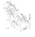
FIG. 1 is a front plan view of the detection device assembly. -
FIG. 2 is an enlarged partial front plan view of the adjustment scale of the device. -
FIG. 3 is a rear plan view of the detection device assembly. -
FIG. 4 is a front perspective view of the device roller assembly. -
FIG. 5 a rear perspective view of the detection device assembly. -
FIG. 6 is a front plan view of the detection device encountering a strip stock splice. -
FIG. 7 is a rear perspective view of the detection device responding to a splice encounter. -
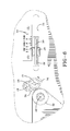
FIG. 8 is a front plan view of the detection device encountering a stock-out occurrence. -
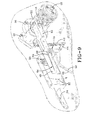
FIG. 9 is a rear perspective view of the detection device responding to the stock-out occurrence. -
FIG. 10 is a front plan view of the detection device adjusted for a thinner stock utilization. -
FIG. 11 is a rear perspective view of the detection device adjusted for a thinner stock utilization. - Referring initially to
FIGS. 1 ,2 ,3 ,4 , and5 , adetection device 10 is shown for detecting thickness anomaly within a strip stock. Thedetection device 10 is useful for myriad applications such as in a tire building line having non-continuous stock preparation. The ply stock and spiral overlay stock in conventional tire building are wound on large spools and have splices built in during stock preparation in order to form a continuous strip or sheet. Such splices create a discontinuity in the tire and are generally undesirable. Thedevice 10 operates in one aspect to detect the presence of such double thickness overlap splices in the stock and, additionally, as will be explained, provide the dual function of detecting a stock-out situation for a wide range of stock thicknesses. -
FIGS. 1 through 5 illustrate a positioning ofdevice 10 at some convenient location after a strip or sheet ofstock 72 has been removed from a stock spool (not shown). Thedevice assembly 10 includes amounting plate 12 having apinch roller 14 andstationary roller 20 rotationally mounted thereto. Theroller 20 rotates about anaxis 22. Thepinch roller 14 is rigidly affixed to apivot arm 16 that connects to apivot shaft 18 extending through theplate 10.Pinch roller 14 rotates about apin 19 as shown. Thestationary roller 20 receives the strip ofstock 72 thereabout and may be driven such as bymotor 23 or free wheeling. Thepinch roller 14 is mounted on thepivot arm 16 which is rigidly attached to thepivot shaft 18. Shaft 18 is free to pivot in a bearinghousing 40 mounted to theplate 12. - On the back side of the plate 12 a
photoeye mask 48 andpivot arm 46 are rigidly clamped to thepivot shaft 18. The photoeye mask is a thin plate having anelongate photoeye slot 64. Theslot 64 is tapered between a leadingslot end 66 and atrailing slot end 68 with at a taper angle of 2.45 degrees. Theslot 64 is further cut so that the slot centerline is at an angle of 3.96 degrees to along edge 50 of themask 48 as shown. The slot taper angle provides a narrower gap when the photoeye is adjusted by moving it to the left , which is done for thinner gauge strips. The combination of moving the sensing point further from the pinch roller pivot shaft and the narrower slot there makes it more sensitive when the stock is thinner. The sizing of the slot and taper angle is done to allow the device to trip at approximately +/- 40 percent of the stock gauge, rather than at a specific thickness. - When a different gauge stock is put into the sensor the nominal position of the arm will change, as the pinch roller will be contacting a different thickness. The slot angle is set so that the photoeye beam will be centered in the slot with a single thickness being pinched (nominal position) with the sensor adjusted for the gauge.
- A through-
beam photoeye device 52 is mounted to theplate 12 and includes anoptical transmitter 54 andreceiver 56 pair. A pair ofphotoeye cables pair beam photoeye pair light 62 it either looks through thephotoeye slot 64 or is blocked by themask 48. The through-beam oflight 62 is small in diameter, approximately one mm, by using flexible fiber-optic photoeye cables right angle tips slot 64. - A
spring 42 is connected between themounting plate 12 and the photoeyemask pivot arm 46 throughspring posts pivot arm 46 provides a small torque to thepivot shaft 18 that forces thepinch roller 14 against thestrip 72. The right angle through beam fiber-optic tips photoeye slide bracket 26. Thebracket 26 is mounted in alinear slot 30 in themounting plate 12, providing an axis of movement used for adjusting the splice detection device for different strip thicknesses. The bracket location for a given strip gauge is set by aligning agroove 34 in a bracket T-bar 35 with an appropriate mark on a stripgauge adjustment scale 32 mounted on the front side of themounting plate 12. A handle facilitates repositioning of thebracket 26 along thescale 32 to a desiredstrip thickness value 36. Thebracket 26 is locked at the desired location with a locking screw andknob combination 28 forcing the T-bar 35 against the edge of theslot 30 when tightened. - When the
strip 72 is threaded as shown inFIG. 1 and thephotoeye slide bracket 26 is adjusted to the proper stock nominal thickness along thescale 32, the through-beam 62 of thephotoeye device 52 will be aligned at an appropriate position along theslot 64 and with the center of the taperedslot 64 in thephotoeye mask 48. When asplice 74, constituting a thickness anomaly, passes between thepinch roller 14 and thestationary roller 20, the extra thickness will cause thepinch roller 14 to move indirection 76, causing thepivot shaft 18 to rotate a commensurate extent. Rotation of theshaft 18 forces photoeyemask pivot arm 46 to pivot, forcing a pivotal movement of themask 48 in the direction ofarrow 78. Movement of themask 48 moves the taperedslot 64 out of alignment with thephotoeye beam 62, blocking it. SeeFIGS. 6 and7 . This provides a momentary signal interpreted by the control system that a splice has been detected. Once thesplice 74 passes therollers spring 42 causes thepinch roller 14 to move against thestrip 72, causing themask 48 to resume an aligned position wherein thebeam 62 is re-centered through the throughslot 64. A momentary signal thus signals and is interpreted as the presence of a splice. - As shown in
FIGS. 8 and9 , should the end of thestrip 72 pass between thepinch roller 14 and thestationary roller 20, the absence of the strip will cause the pinch roller to move in direction 80 (opposite to the direction 76), causing thepivot shaft 18 to directionally rotate (in an opposite direction to shown byFIGS. 6 and7 ) a commensurate extent. Rotation of theshaft 18 forces photoeyemask pivot arm 46 to pivot, forcing a pivotal movement of themask 48 in the direction of arrow 82 (opposite toarrow 78 ofFIGS. 6 and7 ). Movement of themask 48 moves theslot 64 out of alignment with thephotoeye beam 62, blocking it. This produces a signal of indefinitely long duration interpreted by the control system as indicative of a stock-out occurrence, i.e. that the strip no longer is present between the rollers.. Once strip stock is re-threaded between the rollers, themask 48 is repositioned from a blocking position back into an aligned position that re-centers thebeam 62 through the through-slot 64. A signal of longer duration thus may be interpreted to signal a stock-out event while a signal of shorter duration the presence of a splice. -
FIGS. 10 and11 illustrate deployment of thedetection device 10 to detect thickness anomaly in a thinner gauge strip orsheet stock 84 having anoverlap splice 86 present. The illustrative gauge setting for theFIG. 1 stock thickness is indicated as .060 of an inch while, inFIGS. 10 and11 , for illustration purposes the gauge is .020 of an inch. For the thinner gauge stock, thebracket 26 is unclamped byclamp 28, moved along theslot 24 until thecursor notch 34 is at the desired thickness.Clamp 28 is tightened to fix the bracket in the desired setting. Movement of theclamp 28, as shown byFIG. 11 , moves thephotoeye device 52 rearward along theslot 64 of thephotoeye mask 48 toward the narrowerslot trailing end 68.Light beam 66 remains centered through the narrower portion ofslot 64 as shown. The detection device thus is calibrated to detect the thickness of the thinner slot and any anomaly present within the strip such assplice 86 or the absence of the strip in a stock-out situation. - From the foregoing, it will be seen that the
detection device 10 detects thickness anomaly within a strip stock region between theroller 20 and the pivotally mountedpinch roller 14. Thephotoeye mask 46 is mounted to pivotally rotate in either a clockwise or counterclockwise direction responsive to directional pivotal movement of thepinch roller 14, whereby indicating either a splice anomaly within the strip or a stock-out anomaly within the strip. Thetapered photoeye slot 64 within thephotoeye mask 46 extends between a wider slot leading end and a narrower slot trailing end to accommodate an adjustment of thedetection device 10 to strips having differing thickness. The transmitting and receivingoptical devices photoeye slot 64 operate in an photoeye mask-aligned position to project a narrow, centered through-beam 62 through thephotoeye slot 64. Right angledoptical device tips beam 62 is blocked by the photoeye mask as the photoeye mask operatively rotates (in either a clockwise or counterclockwise direction) a preset deflection angle out of the photoeye mask-aligned position and into a photoeye mask blocking position. For narrower stock thicknesses, the location of thebeam 62 through the narrower portions of theslot 64 result in a smaller preset deflection angle required to rotate the photoeye mask between the photoeye mask-aligned and photoeye mask blocking positions. - The
tapered photoeye slot 64 and the stripgauge adjustment scale 32 are configured to accomplish two goals with one adjustment when thedetection device 10 is set to a different strip gauge. First, a different strip gauge will result in the nominal position of thepinch roller 14 and thephotoeye mask 48 to change. The strip gaugeadjustment scale markings 32 and the slot angle θ in thephotoeye mask 48 relative to themask leading edge 50 are set such that thephotoeye beam 62 will remain centered in the photoeye slot when the adjustment mechanism is set to match the strip gauge. Secondly, the sensitivity of thedetector device 10 must be adjusted as the strip gauge changes to improve sensing reliability. When a thinner strip is used the photoeye is adjusted by moving farther from thepivot shaft 18 of thepinch roller 14. This increases the sensitivity of the device in two ways. First, the farther from thepivot shaft 10 the more the tapered photoeye slot moves for a given change in strip thickness. Secondarily, the slot is tapered and narrower farther away from the pivot, resulting in less motion of the mask required to block the beam. The slot taper angle and slot position are designed to provide approximately the same percentage of gauge change required to block the photoeye for all gauges. - The
subject device 10 is useful to detect overlapped splices in any machinery processing flexible strip or sheet materials. Examples in the tire building industry would be spiral overlay or ply appliers or letoffs, but the invention contemplates a wider application potential than the tire industry. The small diameter of thebeam 62 minimizes switch hysteresis and improves accuracy while the photoeye mask slot design provides a means to sense dual thickness anomaly such as lap splices and stock-out conditions. The adjustment mechanism utilizing the angled, tapered slot provides both set point and sensitivity modification in a single, readily facilitated adjustment. It will be appreciated that the pinch roller andpivot arm
Claims (15)
- A detection device for detecting a thickness anomaly region within a strip of stock (72), the device (10) comprising:(A) a first roller (20) operatively rotating as the strip of stock (72) passes over a first roller surface;(B) a pivotally mounted pinch roller (14) positioned to operatively pivot about a pivot axis (18) against the strip of stock (72) when passing over the first roller (20);(C) a photoeye mask (48) positioned to rotate about the pivot axis (18) responsive to pivotal movement of the pinch roller (14);(D) a photoeye slot (64) within the photoeye mask (48) extending between a slot leading end (66) and a slot trailing end (68); and(E) a photoeye device comprising paired transmitting and receiving optical devices (54, 56), the transmitting and receiving devices (54, 56) positioned on opposite sides of the photoeye slot (64) of the photoeye mask (48) and operative in an photoeye mask aligned position to project a substantially centered through-beam (52) through the photoeye slot (64) between the transmitting and receiving optical devices (54, 56).
- The detection device of claim 1 wherein the through-beam (52) is blocked by the photoeye mask (48) as the photoeye mask operatively rotates a preset deflection angle out of a photoeye mask aligned position and into a photoeye mask blocking position.
- The detection device of claim 1 or 2 wherein further comprising biasing means (42) for biasing the pinch roller (14) toward the first roller surface.
- The detection device of at least one of the previous claims wherein a magnitude of the preset deflection angle required to rotate the photoeye mask (48) between the photoeye mask-aligned and photoeye mask blocking positions is adjustable and/or wherein the relative position of the transmitting and receiving optical devices (54, 56) along the photoeye slot (64) is adjustable.
- The detection device of at least one of the previous claims wherein the transmitting and receiving optical devices (54, 56) are oriented at right angles to a longitudinal centerline of the slot (64) and the position of the through-beam (52) within the slot operatively calibrates the splice detection device (10) to differing nominal thicknesses of stock.
- The detection device of at least one of the previous claims wherein the photoeye slot (64) narrows in width between the leading and trailing ends (66, 68) and a longitudinal centerline through the photoeye slot (64) is angled with respect to a leading edge (66) of the photoeye mask (48); and/or wherein a longitudinal centerline through the photoeye slot (64) is angled with respect to a leading edge (66) of the photoeye mask (48).
- The detection device of at least one of the previous claims wherein a magnitude of the preset deflection angle required to rotate the photoeye mask (48) between a photoeye mask aligned and a photoeye mask blocking position is operatively adjustable by varying the position of the transmitting and receiving devices (54, 56) along the photoeye slot (64).
- The detection device of claim 7 wherein adjustment of the transmitting and receiving optical devices along the photoeye slot operatively calibrates the splice detection device to differing nominal thicknesses of stock.
- The detection device of at least one of the previous claims wherein the photoeye slot (64) narrows or tapers in width between the leading and trailing ends (66, 68).
- The detection device of at least one of the previous claims wherein the photoeye mask (48) operatively rotates in opposite first and second directions about the pivot axis (18) responsive to a corresponding pivotal movement of the pinch roller (14) in opposite first and second directions.
- The detection device of claim 10 wherein the through-beam (52) is blocked by the photoeye mask (48) as the photoeye mask operatively rotates through a respective first and a second preset deflection angle in either of the first and second directions out of a photoeye mask aligned position and into respective first and second photoeye mask blocking positions.
- The detection device of claim 10 wherein rotation in the first direction of the photoeye mask (48) into a first photoeye mask blocking position is operatively indicative of a stock-out condition between the first roller (20) and the pinch roller (14).
- The detection device of at least one of the previous claims wherein the rotation in the second direction of the photoeye mask (48) into the second photoeye mask blocking position is operatively indicative of the presence of a splice (74) within the strip of stock (72) between the first roller (20) and the pinch roller (14).
- The detection device of at least one of the previous claims wherein the magnitude of the first and second preset deflection angles respectively required to rotate the photoeye mask (48) between the photoeye mask aligned and the first and second photoeye mask blocking positions is adjustable.
- The detection device of at least one of the previous claims, wherein(i) the relative position of the transmitting and receiving optical devices (54, 56) along the photoeye slot (64) and relative distance from the pinch roller (14) is adjustable; and/or(ii) adjustment of the transmitting and receiving optical devices (54, 56) along the photoeye slot (64) and relative distance from the pinch roller (14) operatively calibrates the splice detection device (10) to differing nominal thicknesses of stock (72).
Applications Claiming Priority (1)
| Application Number | Priority Date | Filing Date | Title |
|---|---|---|---|
| US12/888,551 US8222593B2 (en) | 2010-09-23 | 2010-09-23 | Stock thickness anomaly detection device |
Publications (2)
| Publication Number | Publication Date |
|---|---|
| EP2434254A1 true EP2434254A1 (en) | 2012-03-28 |
| EP2434254B1 EP2434254B1 (en) | 2013-09-04 |
Family
ID=45023538
Family Applications (1)
| Application Number | Title | Priority Date | Filing Date |
|---|---|---|---|
| EP11182377.9A Not-in-force EP2434254B1 (en) | 2010-09-23 | 2011-09-22 | Stock thickness anomaly detection device |
Country Status (4)
| Country | Link |
|---|---|
| US (1) | US8222593B2 (en) |
| EP (1) | EP2434254B1 (en) |
| CN (1) | CN102435144B (en) |
| BR (1) | BRPI1104908A2 (en) |
Families Citing this family (3)
| Publication number | Priority date | Publication date | Assignee | Title |
|---|---|---|---|---|
| DE102013200919A1 (en) * | 2013-01-22 | 2014-07-24 | Robert Bosch Gmbh | Apparatus and method for monitoring and calibrating a device for measuring the tread depth of a tire |
| CN108716882B (en) * | 2018-05-10 | 2021-07-02 | 蒋祥初 | Maintenance check out test set of cladding machine |
| CN119793915B (en) * | 2024-12-31 | 2025-12-02 | 北京克莱斯瑞控释药业有限公司 | A quality testing device for transdermal patch production applications |
Citations (8)
| Publication number | Priority date | Publication date | Assignee | Title |
|---|---|---|---|---|
| US1875617A (en) * | 1929-05-31 | 1932-09-06 | Goodyear Tire & Rubber | Measuring instrument |
| US5029837A (en) * | 1988-06-14 | 1991-07-09 | Minolta Camera Kabushiki Kaisha | Sheet feeding apparatus |
| US5213318A (en) * | 1992-01-02 | 1993-05-25 | Am International Incorporated | Signature gatherer with light detector misfeed sensors |
| US20030116724A1 (en) * | 2001-12-24 | 2003-06-26 | Lg N-Sys Inc. | Paper thickness detecting device |
| US20030209657A1 (en) * | 2002-05-08 | 2003-11-13 | Vejtasa David S. | Displacement measurement system and sheet feed system incorporating the same |
| DE10237767C1 (en) * | 2002-08-17 | 2003-11-20 | Nordenia Deutschland Gronau | Detecting frequency and thickness of foreign matter inclusions in sheet passed through rollers, employs optical beam to measure gap width |
| WO2004022323A1 (en) * | 2002-09-03 | 2004-03-18 | Continental Mabor - Indústria De Pneus, S.A. | An automatic control and monitoring system for splice overlapping tolerance in textile ply |
| US7693802B2 (en) * | 2006-01-23 | 2010-04-06 | Neopost Technologies | System for determining postage rates on the basis of the thickness of the mail items |
Family Cites Families (5)
| Publication number | Priority date | Publication date | Assignee | Title |
|---|---|---|---|---|
| DE2315471C3 (en) * | 1973-03-28 | 1981-10-22 | Fritz Schwarzer GmbH, 8000 München | Positioner for electrical tracking devices in registration systems |
| US3894232A (en) * | 1974-05-08 | 1975-07-08 | Teletype Corp | Rotationally adjustable support mechanism |
| CN2155006Y (en) * | 1993-07-02 | 1994-02-02 | 北京泰兴数据工程有限公司 | Paper thickness detecting device |
| KR20060073674A (en) * | 2004-12-24 | 2006-06-28 | 노틸러스효성 주식회사 | Feeder overlap feed detection device and method |
| CN101373133B (en) * | 2007-08-22 | 2010-06-09 | 致伸科技股份有限公司 | Floating type sheet thickness detection device |
-
2010
- 2010-09-23 US US12/888,551 patent/US8222593B2/en not_active Expired - Fee Related
-
2011
- 2011-09-16 BR BRPI1104908-1A patent/BRPI1104908A2/en not_active IP Right Cessation
- 2011-09-22 EP EP11182377.9A patent/EP2434254B1/en not_active Not-in-force
- 2011-09-23 CN CN201110285488.3A patent/CN102435144B/en not_active Expired - Fee Related
Patent Citations (8)
| Publication number | Priority date | Publication date | Assignee | Title |
|---|---|---|---|---|
| US1875617A (en) * | 1929-05-31 | 1932-09-06 | Goodyear Tire & Rubber | Measuring instrument |
| US5029837A (en) * | 1988-06-14 | 1991-07-09 | Minolta Camera Kabushiki Kaisha | Sheet feeding apparatus |
| US5213318A (en) * | 1992-01-02 | 1993-05-25 | Am International Incorporated | Signature gatherer with light detector misfeed sensors |
| US20030116724A1 (en) * | 2001-12-24 | 2003-06-26 | Lg N-Sys Inc. | Paper thickness detecting device |
| US20030209657A1 (en) * | 2002-05-08 | 2003-11-13 | Vejtasa David S. | Displacement measurement system and sheet feed system incorporating the same |
| DE10237767C1 (en) * | 2002-08-17 | 2003-11-20 | Nordenia Deutschland Gronau | Detecting frequency and thickness of foreign matter inclusions in sheet passed through rollers, employs optical beam to measure gap width |
| WO2004022323A1 (en) * | 2002-09-03 | 2004-03-18 | Continental Mabor - Indústria De Pneus, S.A. | An automatic control and monitoring system for splice overlapping tolerance in textile ply |
| US7693802B2 (en) * | 2006-01-23 | 2010-04-06 | Neopost Technologies | System for determining postage rates on the basis of the thickness of the mail items |
Also Published As
| Publication number | Publication date |
|---|---|
| EP2434254B1 (en) | 2013-09-04 |
| CN102435144A (en) | 2012-05-02 |
| BRPI1104908A2 (en) | 2013-02-05 |
| US8222593B2 (en) | 2012-07-17 |
| CN102435144B (en) | 2015-01-07 |
| US20120074302A1 (en) | 2012-03-29 |
Similar Documents
| Publication | Publication Date | Title |
|---|---|---|
| EP2434254B1 (en) | Stock thickness anomaly detection device | |
| EP1040066B1 (en) | Strip guiding apparatus and associated method for maintaining lateral position | |
| US6695027B2 (en) | Speed matching system for a web splicer mechanism in a web-fed printing press or the like | |
| US10946893B2 (en) | Apparatus and method for detecting motor failure | |
| WO2009051469A1 (en) | Live tape position sensor | |
| US11231337B2 (en) | Method for detecting a tensile stress of a circumferential belt | |
| KR20030054157A (en) | Sensing apparatus for thickness of transit body | |
| EP2523883B1 (en) | Unreeling assembly, particularly for labeling devices | |
| JP2008037653A (en) | Roller for transferring and stretching tape material | |
| US11781853B2 (en) | Measurement device and method for measuring an advancement of a cable | |
| US10294056B2 (en) | Web guiding device and device for processing a web of material | |
| EP2067729B1 (en) | Yarn tension sensor for yarn-feeding devices | |
| US5465495A (en) | Lens shape measuring instrument | |
| US12066141B2 (en) | Slippage detection | |
| US20040118965A1 (en) | Fiber payout follower | |
| JP2010063516A (en) | Sewing machine | |
| EP3847300B1 (en) | Sensor device and method for detecting an abnormal condition of a waste ribbon | |
| JPH04225107A (en) | Method and apparatus for measuring waving amount of band plate | |
| JP2001205593A (en) | Method and apparatus for measuring and cutting width of sheet material | |
| US12264027B2 (en) | Media loading devices | |
| JP2718994B2 (en) | Inspection equipment for ear rubber of corded coating sheet | |
| JPH09329514A (en) | Wire tension detector | |
| JPH0616282A (en) | Thickness detector | |
| JPH05147785A (en) | Web alignment device in paper feed section | |
| WO2002066957A1 (en) | A method and a device for positioning a sample |
Legal Events
| Date | Code | Title | Description |
|---|---|---|---|
| PUAI | Public reference made under article 153(3) epc to a published international application that has entered the european phase |
Free format text: ORIGINAL CODE: 0009012 |
|
| AK | Designated contracting states |
Kind code of ref document: A1 Designated state(s): AL AT BE BG CH CY CZ DE DK EE ES FI FR GB GR HR HU IE IS IT LI LT LU LV MC MK MT NL NO PL PT RO RS SE SI SK SM TR |
|
| AX | Request for extension of the european patent |
Extension state: BA ME |
|
| 17P | Request for examination filed |
Effective date: 20120928 |
|
| GRAP | Despatch of communication of intention to grant a patent |
Free format text: ORIGINAL CODE: EPIDOSNIGR1 |
|
| GRAS | Grant fee paid |
Free format text: ORIGINAL CODE: EPIDOSNIGR3 |
|
| GRAA | (expected) grant |
Free format text: ORIGINAL CODE: 0009210 |
|
| AK | Designated contracting states |
Kind code of ref document: B1 Designated state(s): AL AT BE BG CH CY CZ DE DK EE ES FI FR GB GR HR HU IE IS IT LI LT LU LV MC MK MT NL NO PL PT RO RS SE SI SK SM TR |
|
| REG | Reference to a national code |
Ref country code: GB Ref legal event code: FG4D |
|
| REG | Reference to a national code |
Ref country code: CH Ref legal event code: EP |
|
| REG | Reference to a national code |
Ref country code: AT Ref legal event code: REF Ref document number: 630763 Country of ref document: AT Kind code of ref document: T Effective date: 20130915 |
|
| REG | Reference to a national code |
Ref country code: IE Ref legal event code: FG4D |
|
| REG | Reference to a national code |
Ref country code: DE Ref legal event code: R096 Ref document number: 602011002902 Country of ref document: DE Effective date: 20131031 |
|
| REG | Reference to a national code |
Ref country code: NL Ref legal event code: T3 |
|
| REG | Reference to a national code |
Ref country code: AT Ref legal event code: MK05 Ref document number: 630763 Country of ref document: AT Kind code of ref document: T Effective date: 20130904 |
|
| PG25 | Lapsed in a contracting state [announced via postgrant information from national office to epo] |
Ref country code: LT Free format text: LAPSE BECAUSE OF FAILURE TO SUBMIT A TRANSLATION OF THE DESCRIPTION OR TO PAY THE FEE WITHIN THE PRESCRIBED TIME-LIMIT Effective date: 20130904 Ref country code: NO Free format text: LAPSE BECAUSE OF FAILURE TO SUBMIT A TRANSLATION OF THE DESCRIPTION OR TO PAY THE FEE WITHIN THE PRESCRIBED TIME-LIMIT Effective date: 20131204 Ref country code: SE Free format text: LAPSE BECAUSE OF FAILURE TO SUBMIT A TRANSLATION OF THE DESCRIPTION OR TO PAY THE FEE WITHIN THE PRESCRIBED TIME-LIMIT Effective date: 20130904 Ref country code: HR Free format text: LAPSE BECAUSE OF FAILURE TO SUBMIT A TRANSLATION OF THE DESCRIPTION OR TO PAY THE FEE WITHIN THE PRESCRIBED TIME-LIMIT Effective date: 20130904 Ref country code: CY Free format text: LAPSE BECAUSE OF FAILURE TO SUBMIT A TRANSLATION OF THE DESCRIPTION OR TO PAY THE FEE WITHIN THE PRESCRIBED TIME-LIMIT Effective date: 20130814 Ref country code: AT Free format text: LAPSE BECAUSE OF FAILURE TO SUBMIT A TRANSLATION OF THE DESCRIPTION OR TO PAY THE FEE WITHIN THE PRESCRIBED TIME-LIMIT Effective date: 20130904 |
|
| REG | Reference to a national code |
Ref country code: LT Ref legal event code: MG4D |
|
| PG25 | Lapsed in a contracting state [announced via postgrant information from national office to epo] |
Ref country code: FI Free format text: LAPSE BECAUSE OF FAILURE TO SUBMIT A TRANSLATION OF THE DESCRIPTION OR TO PAY THE FEE WITHIN THE PRESCRIBED TIME-LIMIT Effective date: 20130904 Ref country code: PL Free format text: LAPSE BECAUSE OF FAILURE TO SUBMIT A TRANSLATION OF THE DESCRIPTION OR TO PAY THE FEE WITHIN THE PRESCRIBED TIME-LIMIT Effective date: 20130904 Ref country code: LV Free format text: LAPSE BECAUSE OF FAILURE TO SUBMIT A TRANSLATION OF THE DESCRIPTION OR TO PAY THE FEE WITHIN THE PRESCRIBED TIME-LIMIT Effective date: 20130904 Ref country code: SI Free format text: LAPSE BECAUSE OF FAILURE TO SUBMIT A TRANSLATION OF THE DESCRIPTION OR TO PAY THE FEE WITHIN THE PRESCRIBED TIME-LIMIT Effective date: 20130904 Ref country code: GR Free format text: LAPSE BECAUSE OF FAILURE TO SUBMIT A TRANSLATION OF THE DESCRIPTION OR TO PAY THE FEE WITHIN THE PRESCRIBED TIME-LIMIT Effective date: 20131205 |
|
| PG25 | Lapsed in a contracting state [announced via postgrant information from national office to epo] |
Ref country code: BE Free format text: LAPSE BECAUSE OF FAILURE TO SUBMIT A TRANSLATION OF THE DESCRIPTION OR TO PAY THE FEE WITHIN THE PRESCRIBED TIME-LIMIT Effective date: 20130904 Ref country code: CY Free format text: LAPSE BECAUSE OF FAILURE TO SUBMIT A TRANSLATION OF THE DESCRIPTION OR TO PAY THE FEE WITHIN THE PRESCRIBED TIME-LIMIT Effective date: 20130904 |
|
| PG25 | Lapsed in a contracting state [announced via postgrant information from national office to epo] |
Ref country code: CZ Free format text: LAPSE BECAUSE OF FAILURE TO SUBMIT A TRANSLATION OF THE DESCRIPTION OR TO PAY THE FEE WITHIN THE PRESCRIBED TIME-LIMIT Effective date: 20130904 Ref country code: RO Free format text: LAPSE BECAUSE OF FAILURE TO SUBMIT A TRANSLATION OF THE DESCRIPTION OR TO PAY THE FEE WITHIN THE PRESCRIBED TIME-LIMIT Effective date: 20130904 Ref country code: IS Free format text: LAPSE BECAUSE OF FAILURE TO SUBMIT A TRANSLATION OF THE DESCRIPTION OR TO PAY THE FEE WITHIN THE PRESCRIBED TIME-LIMIT Effective date: 20140104 Ref country code: EE Free format text: LAPSE BECAUSE OF FAILURE TO SUBMIT A TRANSLATION OF THE DESCRIPTION OR TO PAY THE FEE WITHIN THE PRESCRIBED TIME-LIMIT Effective date: 20130904 Ref country code: SK Free format text: LAPSE BECAUSE OF FAILURE TO SUBMIT A TRANSLATION OF THE DESCRIPTION OR TO PAY THE FEE WITHIN THE PRESCRIBED TIME-LIMIT Effective date: 20130904 |
|
| PG25 | Lapsed in a contracting state [announced via postgrant information from national office to epo] |
Ref country code: ES Free format text: LAPSE BECAUSE OF FAILURE TO SUBMIT A TRANSLATION OF THE DESCRIPTION OR TO PAY THE FEE WITHIN THE PRESCRIBED TIME-LIMIT Effective date: 20130904 |
|
| REG | Reference to a national code |
Ref country code: DE Ref legal event code: R097 Ref document number: 602011002902 Country of ref document: DE |
|
| PG25 | Lapsed in a contracting state [announced via postgrant information from national office to epo] |
Ref country code: MC Free format text: LAPSE BECAUSE OF FAILURE TO SUBMIT A TRANSLATION OF THE DESCRIPTION OR TO PAY THE FEE WITHIN THE PRESCRIBED TIME-LIMIT Effective date: 20130904 Ref country code: PT Free format text: LAPSE BECAUSE OF FAILURE TO SUBMIT A TRANSLATION OF THE DESCRIPTION OR TO PAY THE FEE WITHIN THE PRESCRIBED TIME-LIMIT Effective date: 20140106 |
|
| REG | Reference to a national code |
Ref country code: IE Ref legal event code: MM4A |
|
| PLBE | No opposition filed within time limit |
Free format text: ORIGINAL CODE: 0009261 |
|
| STAA | Information on the status of an ep patent application or granted ep patent |
Free format text: STATUS: NO OPPOSITION FILED WITHIN TIME LIMIT |
|
| PG25 | Lapsed in a contracting state [announced via postgrant information from national office to epo] |
Ref country code: IE Free format text: LAPSE BECAUSE OF NON-PAYMENT OF DUE FEES Effective date: 20130922 |
|
| 26N | No opposition filed |
Effective date: 20140605 |
|
| REG | Reference to a national code |
Ref country code: DE Ref legal event code: R097 Ref document number: 602011002902 Country of ref document: DE Effective date: 20140605 |
|
| PG25 | Lapsed in a contracting state [announced via postgrant information from national office to epo] |
Ref country code: DK Free format text: LAPSE BECAUSE OF FAILURE TO SUBMIT A TRANSLATION OF THE DESCRIPTION OR TO PAY THE FEE WITHIN THE PRESCRIBED TIME-LIMIT Effective date: 20130904 |
|
| REG | Reference to a national code |
Ref country code: CH Ref legal event code: PL |
|
| PG25 | Lapsed in a contracting state [announced via postgrant information from national office to epo] |
Ref country code: SM Free format text: LAPSE BECAUSE OF FAILURE TO SUBMIT A TRANSLATION OF THE DESCRIPTION OR TO PAY THE FEE WITHIN THE PRESCRIBED TIME-LIMIT Effective date: 20130904 |
|
| PG25 | Lapsed in a contracting state [announced via postgrant information from national office to epo] |
Ref country code: TR Free format text: LAPSE BECAUSE OF FAILURE TO SUBMIT A TRANSLATION OF THE DESCRIPTION OR TO PAY THE FEE WITHIN THE PRESCRIBED TIME-LIMIT Effective date: 20130904 Ref country code: MT Free format text: LAPSE BECAUSE OF FAILURE TO SUBMIT A TRANSLATION OF THE DESCRIPTION OR TO PAY THE FEE WITHIN THE PRESCRIBED TIME-LIMIT Effective date: 20130904 |
|
| PG25 | Lapsed in a contracting state [announced via postgrant information from national office to epo] |
Ref country code: LU Free format text: LAPSE BECAUSE OF NON-PAYMENT OF DUE FEES Effective date: 20130922 Ref country code: CH Free format text: LAPSE BECAUSE OF NON-PAYMENT OF DUE FEES Effective date: 20140930 Ref country code: BG Free format text: LAPSE BECAUSE OF FAILURE TO SUBMIT A TRANSLATION OF THE DESCRIPTION OR TO PAY THE FEE WITHIN THE PRESCRIBED TIME-LIMIT Effective date: 20130904 Ref country code: MK Free format text: LAPSE BECAUSE OF FAILURE TO SUBMIT A TRANSLATION OF THE DESCRIPTION OR TO PAY THE FEE WITHIN THE PRESCRIBED TIME-LIMIT Effective date: 20130904 Ref country code: LI Free format text: LAPSE BECAUSE OF NON-PAYMENT OF DUE FEES Effective date: 20140930 Ref country code: HU Free format text: LAPSE BECAUSE OF FAILURE TO SUBMIT A TRANSLATION OF THE DESCRIPTION OR TO PAY THE FEE WITHIN THE PRESCRIBED TIME-LIMIT; INVALID AB INITIO Effective date: 20110922 Ref country code: RS Free format text: LAPSE BECAUSE OF FAILURE TO SUBMIT A TRANSLATION OF THE DESCRIPTION OR TO PAY THE FEE WITHIN THE PRESCRIBED TIME-LIMIT Effective date: 20131204 |
|
| GBPC | Gb: european patent ceased through non-payment of renewal fee |
Effective date: 20150922 |
|
| PG25 | Lapsed in a contracting state [announced via postgrant information from national office to epo] |
Ref country code: GB Free format text: LAPSE BECAUSE OF NON-PAYMENT OF DUE FEES Effective date: 20150922 |
|
| REG | Reference to a national code |
Ref country code: FR Ref legal event code: PLFP Year of fee payment: 6 |
|
| PGFP | Annual fee paid to national office [announced via postgrant information from national office to epo] |
Ref country code: IT Payment date: 20160916 Year of fee payment: 6 Ref country code: NL Payment date: 20160908 Year of fee payment: 6 |
|
| PGFP | Annual fee paid to national office [announced via postgrant information from national office to epo] |
Ref country code: FR Payment date: 20160817 Year of fee payment: 6 |
|
| PGFP | Annual fee paid to national office [announced via postgrant information from national office to epo] |
Ref country code: DE Payment date: 20160928 Year of fee payment: 6 |
|
| REG | Reference to a national code |
Ref country code: DE Ref legal event code: R119 Ref document number: 602011002902 Country of ref document: DE |
|
| REG | Reference to a national code |
Ref country code: NL Ref legal event code: MM Effective date: 20171001 |
|
| PG25 | Lapsed in a contracting state [announced via postgrant information from national office to epo] |
Ref country code: NL Free format text: LAPSE BECAUSE OF NON-PAYMENT OF DUE FEES Effective date: 20171001 |
|
| REG | Reference to a national code |
Ref country code: FR Ref legal event code: ST Effective date: 20180531 |
|
| PG25 | Lapsed in a contracting state [announced via postgrant information from national office to epo] |
Ref country code: DE Free format text: LAPSE BECAUSE OF NON-PAYMENT OF DUE FEES Effective date: 20180404 |
|
| PG25 | Lapsed in a contracting state [announced via postgrant information from national office to epo] |
Ref country code: IT Free format text: LAPSE BECAUSE OF NON-PAYMENT OF DUE FEES Effective date: 20170922 Ref country code: FR Free format text: LAPSE BECAUSE OF NON-PAYMENT OF DUE FEES Effective date: 20171002 |
|
| PG25 | Lapsed in a contracting state [announced via postgrant information from national office to epo] |
Ref country code: AL Free format text: LAPSE BECAUSE OF FAILURE TO SUBMIT A TRANSLATION OF THE DESCRIPTION OR TO PAY THE FEE WITHIN THE PRESCRIBED TIME-LIMIT Effective date: 20130904 |