EP2434132A2 - Critical flow nozzle for controlling fuel distribution and burner stability - Google Patents
Critical flow nozzle for controlling fuel distribution and burner stability Download PDFInfo
- Publication number
- EP2434132A2 EP2434132A2 EP11172009A EP11172009A EP2434132A2 EP 2434132 A2 EP2434132 A2 EP 2434132A2 EP 11172009 A EP11172009 A EP 11172009A EP 11172009 A EP11172009 A EP 11172009A EP 2434132 A2 EP2434132 A2 EP 2434132A2
- Authority
- EP
- European Patent Office
- Prior art keywords
- fuel
- critical flow
- nozzle
- flow nozzle
- variable
- Prior art date
- Legal status (The legal status is an assumption and is not a legal conclusion. Google has not performed a legal analysis and makes no representation as to the accuracy of the status listed.)
- Granted
Links
Images


Classifications
-
- F—MECHANICAL ENGINEERING; LIGHTING; HEATING; WEAPONS; BLASTING
- F02—COMBUSTION ENGINES; HOT-GAS OR COMBUSTION-PRODUCT ENGINE PLANTS
- F02C—GAS-TURBINE PLANTS; AIR INTAKES FOR JET-PROPULSION PLANTS; CONTROLLING FUEL SUPPLY IN AIR-BREATHING JET-PROPULSION PLANTS
- F02C9/00—Controlling gas-turbine plants; Controlling fuel supply in air- breathing jet-propulsion plants
- F02C9/26—Control of fuel supply
- F02C9/32—Control of fuel supply characterised by throttling of fuel
-
- F—MECHANICAL ENGINEERING; LIGHTING; HEATING; WEAPONS; BLASTING
- F02—COMBUSTION ENGINES; HOT-GAS OR COMBUSTION-PRODUCT ENGINE PLANTS
- F02C—GAS-TURBINE PLANTS; AIR INTAKES FOR JET-PROPULSION PLANTS; CONTROLLING FUEL SUPPLY IN AIR-BREATHING JET-PROPULSION PLANTS
- F02C7/00—Features, components parts, details or accessories, not provided for in, or of interest apart form groups F02C1/00 - F02C6/00; Air intakes for jet-propulsion plants
- F02C7/22—Fuel supply systems
- F02C7/228—Dividing fuel between various burners
-
- F—MECHANICAL ENGINEERING; LIGHTING; HEATING; WEAPONS; BLASTING
- F02—COMBUSTION ENGINES; HOT-GAS OR COMBUSTION-PRODUCT ENGINE PLANTS
- F02C—GAS-TURBINE PLANTS; AIR INTAKES FOR JET-PROPULSION PLANTS; CONTROLLING FUEL SUPPLY IN AIR-BREATHING JET-PROPULSION PLANTS
- F02C7/00—Features, components parts, details or accessories, not provided for in, or of interest apart form groups F02C1/00 - F02C6/00; Air intakes for jet-propulsion plants
- F02C7/22—Fuel supply systems
- F02C7/232—Fuel valves; Draining valves or systems
-
- F—MECHANICAL ENGINEERING; LIGHTING; HEATING; WEAPONS; BLASTING
- F02—COMBUSTION ENGINES; HOT-GAS OR COMBUSTION-PRODUCT ENGINE PLANTS
- F02C—GAS-TURBINE PLANTS; AIR INTAKES FOR JET-PROPULSION PLANTS; CONTROLLING FUEL SUPPLY IN AIR-BREATHING JET-PROPULSION PLANTS
- F02C9/00—Controlling gas-turbine plants; Controlling fuel supply in air- breathing jet-propulsion plants
- F02C9/26—Control of fuel supply
- F02C9/32—Control of fuel supply characterised by throttling of fuel
- F02C9/34—Joint control of separate flows to main and auxiliary burners
-
- F—MECHANICAL ENGINEERING; LIGHTING; HEATING; WEAPONS; BLASTING
- F05—INDEXING SCHEMES RELATING TO ENGINES OR PUMPS IN VARIOUS SUBCLASSES OF CLASSES F01-F04
- F05D—INDEXING SCHEME FOR ASPECTS RELATING TO NON-POSITIVE-DISPLACEMENT MACHINES OR ENGINES, GAS-TURBINES OR JET-PROPULSION PLANTS
- F05D2240/00—Components
- F05D2240/10—Stators
- F05D2240/12—Fluid guiding means, e.g. vanes
- F05D2240/128—Nozzles
-
- F—MECHANICAL ENGINEERING; LIGHTING; HEATING; WEAPONS; BLASTING
- F05—INDEXING SCHEMES RELATING TO ENGINES OR PUMPS IN VARIOUS SUBCLASSES OF CLASSES F01-F04
- F05D—INDEXING SCHEME FOR ASPECTS RELATING TO NON-POSITIVE-DISPLACEMENT MACHINES OR ENGINES, GAS-TURBINES OR JET-PROPULSION PLANTS
- F05D2240/00—Components
- F05D2240/40—Use of a multiplicity of similar components
-
- F—MECHANICAL ENGINEERING; LIGHTING; HEATING; WEAPONS; BLASTING
- F05—INDEXING SCHEMES RELATING TO ENGINES OR PUMPS IN VARIOUS SUBCLASSES OF CLASSES F01-F04
- F05D—INDEXING SCHEME FOR ASPECTS RELATING TO NON-POSITIVE-DISPLACEMENT MACHINES OR ENGINES, GAS-TURBINES OR JET-PROPULSION PLANTS
- F05D2260/00—Function
- F05D2260/96—Preventing, counteracting or reducing vibration or noise
-
- F—MECHANICAL ENGINEERING; LIGHTING; HEATING; WEAPONS; BLASTING
- F05—INDEXING SCHEMES RELATING TO ENGINES OR PUMPS IN VARIOUS SUBCLASSES OF CLASSES F01-F04
- F05D—INDEXING SCHEME FOR ASPECTS RELATING TO NON-POSITIVE-DISPLACEMENT MACHINES OR ENGINES, GAS-TURBINES OR JET-PROPULSION PLANTS
- F05D2270/00—Control
- F05D2270/01—Purpose of the control system
- F05D2270/07—Purpose of the control system to improve fuel economy
Definitions
- Fuel delivery systems for gas turbine engines typically contain many complex components.
- a fuel delivery system can include a flowmeter that provides fuel to a shut off valve, which controls delivery of fuel to flow divider circuitry.
- the flow divider circuitry adjusts the distribution of fuel to the fuel nozzles while the total fuel flow is measured by the flowmeter.
- Gas turbine engines on aircrafts are generally operated under two conditions: low flow and high flow. Low flow conditions include for example ground idle and descent, and high flow operations include take off and cruise.
- the flow divider valve enables unequal fuel flow to the fuel nozzles during specific conditions and equal fuel flow during other conditions. For example, equal flow may be provided to the fuel nozzles during high flow operations and unequal flow may be provided during low flow operations.
- the unequal flow to fuel nozzles of the combustor provides for some quadrants of the combustor to be at a higher pressure than other quadrants. This creates a fixed standing pressure wave in the combustor plenum and prevents a rotating pressure wave from occurring. A rotating wave is undesirable because it creates an intense acoustic tone known as howling.
- a fuel delivery system for delivering fuel to a gas turbine engine includes a fixed critical flow nozzle, a variable critical flow nozzle, a first fuel nozzle and a second fuel nozzle.
- the fixed critical flow nozzle and the variable critical flow nozzle are connected to a fuel source in parallel.
- the fixed critical flow nozzle has an orifice throat with a fixed effective cross-sectional area.
- the variable critical flow nozzle has an orifice throat with a variable effective cross-sectional area.
- the first fuel nozzle is connected to the fixed critical flow nozzle for delivering fuel to the gas turbine engine, and the second fuel nozzle is connected to the variable critical flow nozzle for delivering fuel to the gas turbine engine.
- a method of fuel delivery is also provided.
- FIG. 1 is a schematic of a fuel distribution system having fixed critical flow nozzles and variable critical flow nozzles.
- FIG. 2 is an enlarged cross-sectional view of one fixed critical flow nozzle of FIG. 1 .
- FIGS. 3a and 3b are enlarged cross-sectional views of one variable critical flow nozzle of FIG. 1 at a default position during low fuel flow.
- FIGS. 4a and 4b are enlarged cross-sectional views of one variable critical flow nozzle of FIG. 1 at a transitional position.
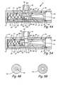
- FIGS. 5a and 5b are enlarged cross-sectional views of one variable critical flow nozzle of FIG. 1 at a fully actuated position during high fuel flow.
- Fuel delivery system 10 for delivering fuel to combustor 12 of a gas turbine engine is illustrated schematically in FIG. 1 .
- Fuel delivery system 10 includes fuel source 14, metering valve 16, shut-off valve (SOV) 18, flowmeter 20, fixed critical flow nozzles 22, variable critical flow nozzles 24, inlet lines 26, first outlet lines 28, second outlet lines 30, first manifolds 32, second manifolds 34, first fuel nozzles 36 and second fuel nozzles 38.
- Metering valve 16 couples to SOV 18, which couples to flowmeter 20.
- Flowmeter 20 directly couples to fixed critical flow nozzles 22 and variable critical flow nozzles 24 by inlet lines 26.
- First outlet lines 28 connect fixed critical flow nozzles 22 to first manifolds 32, which connect to first fuel nozzles 36.
- second outlet lines 30 connect variable critical flow nozzles 24 to second manifolds 34, which supply fuel to second fuel nozzles 38.
- first and second manifolds 32 and 34 are identical, and first fuel nozzles 36 and second fuel nozzles 38 are identical. However, this is not required.
- First outlet lines 28 and second outlet lines 30 are typically unique line lengths to support connecting the plumbing about combustor 12 as required.
- Fuel metering valve 16 regulates fuel flow to combustor 12, and SOV 18 provides leak tight shut-off downstream of fuel metering valve 16.
- Flow metering valve 16 provides low fuel flow during, for example, ground idle and descent, and high fuel flow during, for example, take off and cruise.
- Flowmeter 20 is positioned downstream of SOV 18 so that an inlet of flowmeter 20 is connected to an outlet of SOV 18.
- Flow meter 20 measures the fuel flow to combustor 12. Measurements from flowmeter 20 are typically used to compare total fuel burn flow rate to the aircraft wing tank level gauges.
- Pressurized fuel from flowmeter 20 is delivered to fixed critical flow nozzles 22 and variable critical flow nozzles 24 by inlet lines 26.
- Fixed critical flow nozzles 22 and variable critical flow nozzles 24 are arranged in parallel, and fuel delivered to each fixed critical flow nozzle 22 and variable critical flow nozzle 24 is at the same inlet pressure.
- Fixed critical flow nozzles 22 and variable critical flow nozzles 24 act as flow dividers.
- Fixed critical flow nozzles 22 deliver fuel through first outlet lines 28 to first manifolds 32.
- Each first manifold 32 includes multiple first fuel nozzles 36 which spray fuel into combustor 12 in a desired manner.
- variable critical flow nozzles 24 deliver fuel through second outlet lines 30 to second manifolds 34.
- Each second manifold 34 includes multiple second fuel nozzles 38 which spray fuel into combustor 12 in a desired manner.
- First and second fuel nozzles 36 and 38 are not always provided with equal flow.
- fixed critical flow nozzles 22 and variable critical flow nozzles 24 provide first and second fuel nozzles 36 and 38 with equal flow
- at low flow conditions, such as ground idle and descent fixed critical flow nozzles 22 and variable critical flow nozzles 24 provide first and second fuel nozzles 36 and 38 with unequal flow.
- Fixed critical flow nozzles 22 and variable critical flow nozzles 24 allow automatic fuel flow equalization at high flows and automatic asymmetric or unequal flow at low flows to combustor 12 as described further below
- first and second fuel nozzles 36 and 38 ensures that the fuel flow into the engine quadrants of combustor 12 is equal, of uniform temperature and below the temperature limit. Sustained unequal flow to combustor 12 can cause streaking and hot spots within combustor 12 that can significantly reduce the life of the engine of which combustor 12 is a part.
- second fuel nozzles 38 provide combustor 12 with a lower fuel flow than first fuel nozzles 36.
- second fuel nozzles 38 are located at the three- and nine-o'clock positions in combustor 12 and four first fuel nozzles 36 are equally spaced between second fuel nozzles 38.
- the number and position of first and second fuel nozzles 36 and 38 can be varied.
- fixed critical flow nozzles 22 and variable critical flow nozzles 24 are provided with fuel at equal pressure, and fixed critical flow nozzles 22 and variable critical flow nozzles 24 control the fuel flow to combustor 12 to achieve equal or unequal fuel flow depending on the operating conditions.
- FIG. 2 illustrates an enlarged cross-sectional view of fixed critical flow nozzle 22.
- Arrow F indicates the flow of fuel through fixed critical flow nozzle 22.
- Fuel enters fixed critical flow nozzle 22 at inlet cone 40, flows through orifice throat 42 and exits through recovery section 44.
- Fixed critical flow nozzle 22 can be positioned within housing 46 and attaches to inlet line 26 and first outlet line 28.
- Fixed critical flow nozzle 22 is a nozzle having a converging-diverging shape. Fixed critical flow nozzle 22 converges to a minimum cross-sectional area at orifice throat 42 and then diverges along recovery section 44. The converging section of fixed critical flow nozzle 22 reduces the pressure of the fuel to its vapor pressure point. The diverging shape of recovery section 44 allows pressure recovery. In one example, recovery section 44 has about a 2.5 degree taper, which allows for good pressure recovery resulting in a minimum permanent loss across fixed critical flow nozzle 22.
- the effective cross-sectional area of orifice throat 42 is fixed. That is, the cross-sectional area available for fuel flow through orifice throat 42 is not adjustable in fixed critical flow nozzle 22. In one example, fixed critical flow nozzle has an outside diameter of about 1.0 centimeters (0.4 inches), is about 3.3 centimeters (1.3 inches) long and has a throat diameter of about 0.2 centimeters (0.08 inches).
- Fixed critical flow nozzle 22 operates at a limiting condition known as critical or choked flow. Choked flow occurs when the Venturi effect acting on the fuel flowing through fixed critical flow nozzle 22 decreases the liquid pressure of the fuel to that of the liquid vapor pressure at the prevailing temperature. Orifice throat 42 is sized so that the differential pressure generated from inlet cone 40 to orifice throat 42 reduces the fuel to its vapor pressure point. Pressures lower than the vapor pressure cannot be reached because the volumetric expansion required is prevented by the fixed walls of fixed critical flow nozzle 22.
- Fixed critical flow nozzle 22 operates at choked flow during high and low flow operations. Choked flow provides a fixed mass flow rate for a specified fluid at a given upstream pressure and temperature. The mass flow rate at choked flow is unaffected by fluctuations, surges or changes in the downstream pressure. The mass flow rate through fixed critical flow nozzle 22 is adjusted by adjusting the upstream pressure of the fuel (i.e., the pressure at inlet cone 40). Increasing the upstream pressure of the fuel results in an increased mass flow rate at choked flow. For example, at low flow requirements, fuel at low pressure is supplied to fixed critical flow nozzle 22. As the engine power and fuel flow request increases, the pressure of the fuel is increased in order to increase the flow rate through fixed critical flow nozzle 22 at choked flow.
- FIG. 3A illustrates an enlarged cross-sectional view of variable critical flow nozzle 24 at a default position such as at start or low fuel flow.
- FIG. 3B illustrates a cross-sectional view of variable critical flow nozzle 24 taken along line 3B-3B of FIG. 3A. FIGS. 3A and 3B will be discussed together.
- Variable critical flow nozzle 24 is supply pressure actuated and includes inlet 48, outlet 50, flow annulus 52, nozzle 54 (having inlet cone 56, orifice throat 58 and recovery section 60), nozzle seal 62, housing 64, needle 66 (having tapered portion 68 and straight portion 70), piston 72 (having spring 74, shims 76 and back chamber 78), sliding piston seal 80, sense or vent line 82 (having damping orifice 84), fingers 86a, 86b, 86c and 86d, spacer 88 and snap ring 90.
- pressurized fuel enters through inlet 48, flows through flow annulus 52 and nozzle 54, and exits at outlet 50.
- Nozzle 54 regulates the mass flow rate of fuel using the Venturi principle. Needle 66 extends from piston 72 into nozzle 54. Piston 72 actuates to reposition needle 66 and change the effective cross-sectional area of orifice throat 58 of nozzle 54.
- Nozzle 54, needle 66 and piston 72 are enclosed by housing 64.
- Sliding piston seal 80 can be used to form a seal between housing 64 and piston 72 and prevent or reduce leaking between piston 72 and housing 64 as piston 72 actuates.
- nozzle seal 62 can form a seal between nozzle 54 and housing 64 to prevent or reduce leaking between housing 64 and nozzle 54.
- Nozzle 54 is similar to the nozzle of fixed critical flow nozzle 22 of FIG. 2 , and includes inlet cone 56, orifice throat 58 and recovery section 60. Nozzle 54 operates under the Venturi principle. The converging shape of nozzle 54 from inlet cone 56 to orifice throat 58 compresses the fuel to its vapor pressure point. Orifice throat 58 has the same diameter as orifice throat 42 of fixed critical flow nozzle 22 of FIG. 2 . However, as shown in FIG. 3B , the effective cross-sectional area of orifice throat 58 is smaller than that of orifice throat 42 because of needle 66. The diverging downstream shape of nozzle 54 from orifice throat 58 to recovery section 60 enables sufficient pressure recovery.
- orifice throat 58 has a diameter of about 0.2 centimeters
- recovery section 60 has about a 2.5 degree taper
- housing 64 is about 1.3 centimeters in diameter (0.5 inches) and about 8.4 centimeters long (3.3 inches).
- needle 66 extends from piston 72 into orifice throat 58.
- Needle 66 includes tapered portion 68 and straight portion 70.
- Straight portion 70 is located between piston 72 and tapered portion 68.
- needle 66 reduces the effective cross-sectional area of orifice throat 58. That is, needle 66 reduces the cross-sectional area available for fluid flow.
- straight portion 70 of needle 66 is positioned in orifice throat 58, such that orifice throat 58 of variable critical flow nozzle 24 has a minimum effective cross-sectional area.
- Straight portion 70 has a constant diameter over a short range to produce a constant reduced effective cross-sectional area over a specified low fuel pressure range.
- Piston 72 includes spring 74, shims 76 and back chamber 78.
- Spring 74 biases piston 72 to move needle 66 towards nozzle 54 along the horizontal axis.
- Shims 76 can be added or removed to change the initial compression of spring 74. Shims 76 enable piston 72 to be tuned without introducing holes into housing 64 which can be the site of leakage.
- back chamber 78 contains low pressure fuel that biases piston 72 towards nozzle 54.
- Sense line 82 is connected between back chamber 78 and outlet 50.
- Sense line 82 enables low pressure fuel from outlet 50 to enter or exit back chamber 78 when piston 72 actuates.
- the volume of fuel displaced during actuation is small and does not have a significant effect on the downstream burner operations.
- Damping orifice 84 may be used in sense line 82 to smooth the flow of fuel through sense line 82. Damping orifice 84 reduces bouncing of piston 72 due to pulsating hydraulic pressure.
- Fingers 86a, 86b, 86c and 86d extend axially from piston 72 and approximately parallel to needle 66. The ends of fingers 86 opposite piston 72 abut nozzle 54 in the default position. Fingers 86 limit the axial movement of piston 72. Fingers 86 position needle 66 at a predetermined depth in nozzle 54 at low flow operation. Fingers 86 are arranged so fuel can flow into flow annulus 52 when piston 72 is at maximum extension and fingers 86 contact nozzle 54. Fingers 86 do not prevent fuel flow into flow annulus 52. Although four fingers 86 extend from piston 72 in FIG. 3A , more or less fingers 86 can be used.
- Housing 64 surrounds piston 72, needle 66 and nozzle 54.
- Inlet 48 is connected to fuel inlet line and outlet 50 is connected to second outlet line 30 as described above with respect to FIG. 1 .
- inlet 48 and outlet 50 are shown as threaded connections, inlet 48 and outlet 50 can use alternative connection methods.
- Spacer 88 and snap ring 90 can be used at outlet 50. Spacer 88 holds nozzle 54 seated at a desired location and snap ring 90 keeps the assembly in position. Alternatively, spacer 88 and snap ring 90 may not be present.
- Variable critical flow nozzle 24 is designed without fasteners, such as screws, in housing 64 in order to reduce leakage.
- Housing 64 is designed so that the components of variable critical flow nozzle 24 can be inserted through outlet 50 during assembly.
- Housing 64 can also include step 92. Step 92 prevents nozzle 54 from moving axially towards piston 72 (i.e., to the left), and step 92 and snap ring 90 maintain nozzle 54 from moving axially away from piston 72 (i.e., to the right).
- Piston 72 changes the axial location of needle 66 in orifice throat 58 to change the effective cross-sectional area of orifice throat 58. Piston 72 automatically adjusts the axial position of needle 66 based on the supply pressure of the fuel at inlet 48. Piston 72 moves axially as a function of the fuel pressure of flow annulus 52, the fuel pressure of back chamber 78 and spring 74. In use, the pressurized fuel enters flow annulus 52 and pushes against piston 72. Piston 72 moves backwards or to the left along the axial axis when the force of the inlet fuel in flow annulus 52 is greater than the combined force from spring 74 and the low pressure fuel in back chamber 78. The low pressure fuel of back chamber 78 reduces the size of spring 74.
- orifice throat effective cross-sectional area of orifice throat 58 can increase because needle 66 is repositioned. Under the Venturi effect, increasing the effective cross-sectional area of orifice throat 58 increases the flow rate at the choke flow of nozzle 54.
- FIGS. 3A and 3B illustrate variable critical flow nozzle 24 at low flow operation and having a minimum orifice throat effective cross-sectional area. Piston 72 is automatically supply pressure actuated and increases the effective cross-sectional area of orifice throat 58 at higher fuel flows (and corresponding higher pressures).
- FIGS. 4A and 4B illustrate variable critical flow nozzle 24 at a transition position between low and high flows
- FIGS. 5A and 5B illustrate variable critical flow nozzle 24 at high flow operation and having a maximum orifice throat effective cross-sectional area.
- FIGS. 4A and 4B illustrate variable critical flow nozzle 24 at a transitional stage (i.e., having fuel pressure between the high and low fuel pressures).
- tapered portion 68 of needle 66 is positioned at orifice throat 58. Tapered portion 68 of needle 66 has a smaller diameter than straight portion 70. This results in variable critical flow nozzle 24 of FIG. 4A and 4B having a greater effective cross-sectional area at orifice throat 58 than that of FIGS. 3A and 3B . Tapered portion 68 of needle 66 has a gentle taper which reduces or minimizes perturbations in fuel flow as needle 66 enters and exits nozzle 54.
- the transition stage is transitory.
- the transition stage is not a typical operating mode and is generally only experienced when transitioning between high and low flow operations.
- Variable critical flow nozzle 24 can be designed so that the effective cross-sectional area of orifice throat 58 is at a minimum during low flow operations, is at a maximum during high flow operations and transitions at a non-critical zone.
- variable critical flow nozzle 24 may transition at a pressure above that of ground idle and below that of cruise.
- FIG. 5A and 5B illustrate variable critical flow nozzle 24 at this range.
- needle 66 is fully removed from orifice throat 58.
- the effective cross-sectional area of orifice throat 58 is at a maximum in FIG. 5A and 5B .
- variable critical flow nozzle 24 of FIG. 5A and 5B has a larger effective orifice throat cross-sectional area, this variable critical flow nozzle 24 has a higher flow rate at choked flow compared to those of FIGS. 3A, 3B , 4A and 4B .
- nozzle 54 of variable critical flow nozzle 24 has the same diameter orifice throat as that of fixed critical flow nozzle 22 of FIG. 2 . Therefore, with needle 66 no longer occupying a portion of orifice throat 58, the effective cross-sectional area of orifice throat 58 of variable critical flow nozzle 24 and the effective cross-sectional area of orifice throat 42 of fixed critical flow nozzle 22 of FIG. 2 are equal.
- fuel delivery system 10 of FIG. 1 includes fixed critical flow nozzles 22 and variable critical flow nozzles 24.
- Fixed critical flow nozzles 22 and variable critical flow nozzles 24 operate at choked flow so that desired flow rates are produced at high and low flow operations.
- Fixed critical flow nozzles 22 and variable critical flow nozzles 24 divide the fuel flow between several first manifolds 32 and second manifolds 34, which provide the fuel to combustor 12. The use of fixed critical flow nozzles 22 and variable critical flow nozzles 24 enable equal flow to combustor 12 under certain operating conditions and unequal flow under other operating conditions.
- flow divider valves were used to divide the flow of fuel between the manifolds. Tighter tolerances are achievable in manufacturing fixed critical flow nozzles 22 and variable critical flow nozzles 24 compared to the manufacturing of flow divider valves. These tighter tolerances result in splitting the fuel flow with increased precision when fixed critical flow nozzles 22 and variable critical flow nozzles 24 are used.
- Variable critical flow nozzles 24 are supply pressure actuated and automatically cause an imbalance of flow going to first and second fuel nozzles 36 and 38 at low pressure. At high pressures, variable critical flow nozzles 24 automatically adjust the effective cross-sectional area of orifice throat 58 so that the effective cross-sectional areas of orifice throats 42 and 58 are equal. This results in providing first and second fuel nozzles 36 and 38 with equal flow. At low flow, variable critical flow nozzles 24 automatically adjust the effective cross-sectional area of orifice throat 58 so that the effective cross-sectional area is less than that of fixed critical flow nozzles 22.
- variable critical flow nozzles 24 providing a lower fuel flow rate to second manifold 34 compared to that provided by fixed critical flow nozzles 22 to first manifolds 32.
- the unequal or asymmetric flow provides for some quadrants of combustor 12 to be at a higher pressure than others and can reduce howling.
- Variable critical flow nozzle 24 seamlessly switches between equal and unequal flow at high and low flow respectively. Variable critical flow nozzle 24 automatically actuates based on the inlet pressure. Variable critical flow nozzle 24 is not electronically controlled and additional control logic is not necessary.
Landscapes
- Engineering & Computer Science (AREA)
- Chemical & Material Sciences (AREA)
- Combustion & Propulsion (AREA)
- Mechanical Engineering (AREA)
- General Engineering & Computer Science (AREA)
- Feeding And Controlling Fuel (AREA)
- Gas Burners (AREA)
Abstract
Description
- Fuel delivery systems for gas turbine engines typically contain many complex components. For example, a fuel delivery system can include a flowmeter that provides fuel to a shut off valve, which controls delivery of fuel to flow divider circuitry. The flow divider circuitry adjusts the distribution of fuel to the fuel nozzles while the total fuel flow is measured by the flowmeter. Gas turbine engines on aircrafts are generally operated under two conditions: low flow and high flow. Low flow conditions include for example ground idle and descent, and high flow operations include take off and cruise.
- The flow divider valve enables unequal fuel flow to the fuel nozzles during specific conditions and equal fuel flow during other conditions. For example, equal flow may be provided to the fuel nozzles during high flow operations and unequal flow may be provided during low flow operations. The unequal flow to fuel nozzles of the combustor provides for some quadrants of the combustor to be at a higher pressure than other quadrants. This creates a fixed standing pressure wave in the combustor plenum and prevents a rotating pressure wave from occurring. A rotating wave is undesirable because it creates an intense acoustic tone known as howling.
- Current fuel delivery systems are expensive and heavy. Additionally, the current fuel flow delivery systems are complex and typically require complex control systems.
- A fuel delivery system for delivering fuel to a gas turbine engine includes a fixed critical flow nozzle, a variable critical flow nozzle, a first fuel nozzle and a second fuel nozzle. The fixed critical flow nozzle and the variable critical flow nozzle are connected to a fuel source in parallel. The fixed critical flow nozzle has an orifice throat with a fixed effective cross-sectional area. The variable critical flow nozzle has an orifice throat with a variable effective cross-sectional area. The first fuel nozzle is connected to the fixed critical flow nozzle for delivering fuel to the gas turbine engine, and the second fuel nozzle is connected to the variable critical flow nozzle for delivering fuel to the gas turbine engine. A method of fuel delivery is also provided.
-
FIG. 1 is a schematic of a fuel distribution system having fixed critical flow nozzles and variable critical flow nozzles. -
FIG. 2 is an enlarged cross-sectional view of one fixed critical flow nozzle ofFIG. 1 . -
FIGS. 3a and 3b are enlarged cross-sectional views of one variable critical flow nozzle ofFIG. 1 at a default position during low fuel flow. -
FIGS. 4a and 4b are enlarged cross-sectional views of one variable critical flow nozzle ofFIG. 1 at a transitional position. -
FIGS. 5a and 5b are enlarged cross-sectional views of one variable critical flow nozzle ofFIG. 1 at a fully actuated position during high fuel flow. -
Fuel delivery system 10 for delivering fuel tocombustor 12 of a gas turbine engine is illustrated schematically inFIG. 1 .Fuel delivery system 10 includesfuel source 14,metering valve 16, shut-off valve (SOV) 18,flowmeter 20, fixedcritical flow nozzles 22, variablecritical flow nozzles 24,inlet lines 26,first outlet lines 28,second outlet lines 30,first manifolds 32,second manifolds 34,first fuel nozzles 36 andsecond fuel nozzles 38.Metering valve 16 couples toSOV 18, which couples toflowmeter 20.Flowmeter 20 directly couples to fixedcritical flow nozzles 22 and variablecritical flow nozzles 24 byinlet lines 26.First outlet lines 28 connect fixedcritical flow nozzles 22 to firstmanifolds 32, which connect tofirst fuel nozzles 36. Similarly,second outlet lines 30 connect variablecritical flow nozzles 24 tosecond manifolds 34, which supply fuel tosecond fuel nozzles 38. As illustrated inFIG. 1 , first andsecond manifolds first fuel nozzles 36 andsecond fuel nozzles 38 are identical. However, this is not required.First outlet lines 28 andsecond outlet lines 30 are typically unique line lengths to support connecting the plumbing aboutcombustor 12 as required. -
Fuel metering valve 16 regulates fuel flow tocombustor 12, andSOV 18 provides leak tight shut-off downstream offuel metering valve 16.Flow metering valve 16 provides low fuel flow during, for example, ground idle and descent, and high fuel flow during, for example, take off and cruise.Flowmeter 20 is positioned downstream ofSOV 18 so that an inlet offlowmeter 20 is connected to an outlet ofSOV 18.Flow meter 20 measures the fuel flow tocombustor 12. Measurements fromflowmeter 20 are typically used to compare total fuel burn flow rate to the aircraft wing tank level gauges. - Pressurized fuel from
flowmeter 20 is delivered to fixedcritical flow nozzles 22 and variablecritical flow nozzles 24 byinlet lines 26. Fixedcritical flow nozzles 22 and variablecritical flow nozzles 24 are arranged in parallel, and fuel delivered to each fixedcritical flow nozzle 22 and variablecritical flow nozzle 24 is at the same inlet pressure. Fixedcritical flow nozzles 22 and variablecritical flow nozzles 24 act as flow dividers. Fixedcritical flow nozzles 22 deliver fuel throughfirst outlet lines 28 to firstmanifolds 32. Eachfirst manifold 32 includes multiplefirst fuel nozzles 36 which spray fuel intocombustor 12 in a desired manner. Similarly, variablecritical flow nozzles 24 deliver fuel throughsecond outlet lines 30 tosecond manifolds 34. Eachsecond manifold 34 includes multiplesecond fuel nozzles 38 which spray fuel intocombustor 12 in a desired manner. - First and
second fuel nozzles critical flow nozzles 22 and variablecritical flow nozzles 24 provide first andsecond fuel nozzles critical flow nozzles 22 and variablecritical flow nozzles 24 provide first andsecond fuel nozzles critical flow nozzles 22 and variablecritical flow nozzles 24 allow automatic fuel flow equalization at high flows and automatic asymmetric or unequal flow at low flows tocombustor 12 as described further below - Providing equal flow to first and
second fuel nozzles combustor 12 is equal, of uniform temperature and below the temperature limit. Sustained unequal flow tocombustor 12 can cause streaking and hot spots withincombustor 12 that can significantly reduce the life of the engine of whichcombustor 12 is a part. - It can be desirable to have unequal or asymmetrical flow at low fuel flows. The unequal flow provides for some quadrants of
combustor 12 to be at a higher pressure than other quadrants allowing a fixed standing pressure wave to be present incombustor 12. This condition can prevent a blow out of the engine during low fuel flow conditions and can reduce howling. At low fuel flows infuel delivery system 10,second fuel nozzles 38 providecombustor 12 with a lower fuel flow thanfirst fuel nozzles 36. In one example,second fuel nozzles 38 are located at the three- and nine-o'clock positions incombustor 12 and fourfirst fuel nozzles 36 are equally spaced betweensecond fuel nozzles 38. However, the number and position of first andsecond fuel nozzles fuel delivery system 10, fixedcritical flow nozzles 22 and variablecritical flow nozzles 24 are provided with fuel at equal pressure, and fixedcritical flow nozzles 22 and variablecritical flow nozzles 24 control the fuel flow tocombustor 12 to achieve equal or unequal fuel flow depending on the operating conditions. -
FIG. 2 illustrates an enlarged cross-sectional view of fixedcritical flow nozzle 22. Arrow F indicates the flow of fuel through fixedcritical flow nozzle 22. Fuel enters fixedcritical flow nozzle 22 atinlet cone 40, flows throughorifice throat 42 and exits throughrecovery section 44. Fixedcritical flow nozzle 22 can be positioned withinhousing 46 and attaches toinlet line 26 andfirst outlet line 28. - Fixed
critical flow nozzle 22 is a nozzle having a converging-diverging shape. Fixedcritical flow nozzle 22 converges to a minimum cross-sectional area atorifice throat 42 and then diverges alongrecovery section 44. The converging section of fixedcritical flow nozzle 22 reduces the pressure of the fuel to its vapor pressure point. The diverging shape ofrecovery section 44 allows pressure recovery. In one example,recovery section 44 has about a 2.5 degree taper, which allows for good pressure recovery resulting in a minimum permanent loss across fixedcritical flow nozzle 22. The effective cross-sectional area oforifice throat 42 is fixed. That is, the cross-sectional area available for fuel flow throughorifice throat 42 is not adjustable in fixedcritical flow nozzle 22. In one example, fixed critical flow nozzle has an outside diameter of about 1.0 centimeters (0.4 inches), is about 3.3 centimeters (1.3 inches) long and has a throat diameter of about 0.2 centimeters (0.08 inches). - Fixed
critical flow nozzle 22 operates at a limiting condition known as critical or choked flow. Choked flow occurs when the Venturi effect acting on the fuel flowing through fixedcritical flow nozzle 22 decreases the liquid pressure of the fuel to that of the liquid vapor pressure at the prevailing temperature.Orifice throat 42 is sized so that the differential pressure generated frominlet cone 40 to orificethroat 42 reduces the fuel to its vapor pressure point. Pressures lower than the vapor pressure cannot be reached because the volumetric expansion required is prevented by the fixed walls of fixedcritical flow nozzle 22. - Fixed
critical flow nozzle 22 operates at choked flow during high and low flow operations. Choked flow provides a fixed mass flow rate for a specified fluid at a given upstream pressure and temperature. The mass flow rate at choked flow is unaffected by fluctuations, surges or changes in the downstream pressure. The mass flow rate through fixedcritical flow nozzle 22 is adjusted by adjusting the upstream pressure of the fuel (i.e., the pressure at inlet cone 40). Increasing the upstream pressure of the fuel results in an increased mass flow rate at choked flow. For example, at low flow requirements, fuel at low pressure is supplied to fixedcritical flow nozzle 22. As the engine power and fuel flow request increases, the pressure of the fuel is increased in order to increase the flow rate through fixedcritical flow nozzle 22 at choked flow. -
Orifice throat 42 of fixedcritical flow nozzle 22 has a fixed effective cross-sectional area. In contrast, the orifice throat of variablecritical flow nozzle 24 has a variable effective cross-sectional area.FIG. 3A illustrates an enlarged cross-sectional view of variablecritical flow nozzle 24 at a default position such as at start or low fuel flow.FIG. 3B illustrates a cross-sectional view of variablecritical flow nozzle 24 taken alongline 3B-3B ofFIG. 3A. FIGS. 3A and 3B will be discussed together. - Variable
critical flow nozzle 24 is supply pressure actuated and includesinlet 48,outlet 50,flow annulus 52, nozzle 54 (havinginlet cone 56,orifice throat 58 and recovery section 60),nozzle seal 62,housing 64, needle 66 (having taperedportion 68 and straight portion 70), piston 72 (havingspring 74, shims 76 and back chamber 78), slidingpiston seal 80, sense or vent line 82 (having damping orifice 84),fingers spacer 88 andsnap ring 90. In use, pressurized fuel enters throughinlet 48, flows throughflow annulus 52 andnozzle 54, and exits atoutlet 50.Nozzle 54 regulates the mass flow rate of fuel using the Venturi principle.Needle 66 extends frompiston 72 intonozzle 54.Piston 72 actuates to repositionneedle 66 and change the effective cross-sectional area oforifice throat 58 ofnozzle 54. -
Nozzle 54,needle 66 andpiston 72 are enclosed byhousing 64. Slidingpiston seal 80 can be used to form a seal betweenhousing 64 andpiston 72 and prevent or reduce leaking betweenpiston 72 andhousing 64 aspiston 72 actuates. Similarly,nozzle seal 62 can form a seal betweennozzle 54 andhousing 64 to prevent or reduce leaking betweenhousing 64 andnozzle 54. -
Nozzle 54 is similar to the nozzle of fixedcritical flow nozzle 22 ofFIG. 2 , and includesinlet cone 56,orifice throat 58 andrecovery section 60.Nozzle 54 operates under the Venturi principle. The converging shape ofnozzle 54 frominlet cone 56 to orificethroat 58 compresses the fuel to its vapor pressure point.Orifice throat 58 has the same diameter asorifice throat 42 of fixedcritical flow nozzle 22 ofFIG. 2 . However, as shown inFIG. 3B , the effective cross-sectional area oforifice throat 58 is smaller than that oforifice throat 42 because ofneedle 66. The diverging downstream shape ofnozzle 54 fromorifice throat 58 torecovery section 60 enables sufficient pressure recovery. In one example,orifice throat 58 has a diameter of about 0.2 centimeters,recovery section 60 has about a 2.5 degree taper andhousing 64 is about 1.3 centimeters in diameter (0.5 inches) and about 8.4 centimeters long (3.3 inches). - As shown in
FIG. 3A ,needle 66 extends frompiston 72 intoorifice throat 58.Needle 66 includes taperedportion 68 andstraight portion 70.Straight portion 70 is located betweenpiston 72 and taperedportion 68. By occupying the center oforifice throat 58,needle 66 reduces the effective cross-sectional area oforifice throat 58. That is,needle 66 reduces the cross-sectional area available for fluid flow. InFIG. 3A and 3B ,straight portion 70 ofneedle 66 is positioned inorifice throat 58, such thatorifice throat 58 of variablecritical flow nozzle 24 has a minimum effective cross-sectional area.Straight portion 70 has a constant diameter over a short range to produce a constant reduced effective cross-sectional area over a specified low fuel pressure range. -
Piston 72 includesspring 74, shims 76 and backchamber 78.Spring 74biases piston 72 to moveneedle 66 towardsnozzle 54 along the horizontal axis.Shims 76 can be added or removed to change the initial compression ofspring 74.Shims 76 enablepiston 72 to be tuned without introducing holes intohousing 64 which can be the site of leakage. Additionally, backchamber 78 contains low pressure fuel thatbiases piston 72 towardsnozzle 54. -
Sense line 82 is connected betweenback chamber 78 andoutlet 50.Sense line 82 enables low pressure fuel fromoutlet 50 to enter or exit backchamber 78 whenpiston 72 actuates. The volume of fuel displaced during actuation is small and does not have a significant effect on the downstream burner operations. Dampingorifice 84 may be used insense line 82 to smooth the flow of fuel throughsense line 82. Dampingorifice 84 reduces bouncing ofpiston 72 due to pulsating hydraulic pressure. -
Fingers piston 72 and approximately parallel toneedle 66. The ends of fingers 86opposite piston 72abut nozzle 54 in the default position. Fingers 86 limit the axial movement ofpiston 72. Fingers 86position needle 66 at a predetermined depth innozzle 54 at low flow operation. Fingers 86 are arranged so fuel can flow intoflow annulus 52 whenpiston 72 is at maximum extension and fingers 86contact nozzle 54. Fingers 86 do not prevent fuel flow intoflow annulus 52. Although four fingers 86 extend frompiston 72 inFIG. 3A , more or less fingers 86 can be used. -
Housing 64 surroundspiston 72,needle 66 andnozzle 54.Inlet 48 is connected to fuel inlet line andoutlet 50 is connected tosecond outlet line 30 as described above with respect toFIG. 1 . Althoughinlet 48 andoutlet 50 are shown as threaded connections,inlet 48 andoutlet 50 can use alternative connection methods. -
Spacer 88 andsnap ring 90 can be used atoutlet 50.Spacer 88 holdsnozzle 54 seated at a desired location andsnap ring 90 keeps the assembly in position. Alternatively,spacer 88 andsnap ring 90 may not be present. - Variable
critical flow nozzle 24 is designed without fasteners, such as screws, inhousing 64 in order to reduce leakage.Housing 64 is designed so that the components of variablecritical flow nozzle 24 can be inserted throughoutlet 50 during assembly.Housing 64 can also includestep 92.Step 92 preventsnozzle 54 from moving axially towards piston 72 (i.e., to the left), and step 92 andsnap ring 90 maintainnozzle 54 from moving axially away from piston 72 (i.e., to the right). -
Piston 72 changes the axial location ofneedle 66 inorifice throat 58 to change the effective cross-sectional area oforifice throat 58.Piston 72 automatically adjusts the axial position ofneedle 66 based on the supply pressure of the fuel atinlet 48.Piston 72 moves axially as a function of the fuel pressure offlow annulus 52, the fuel pressure ofback chamber 78 andspring 74. In use, the pressurized fuel entersflow annulus 52 and pushes againstpiston 72.Piston 72 moves backwards or to the left along the axial axis when the force of the inlet fuel inflow annulus 52 is greater than the combined force fromspring 74 and the low pressure fuel inback chamber 78. The low pressure fuel ofback chamber 78 reduces the size ofspring 74. - When
piston 72 moves backwards, the orifice throat effective cross-sectional area oforifice throat 58 can increase becauseneedle 66 is repositioned. Under the Venturi effect, increasing the effective cross-sectional area oforifice throat 58 increases the flow rate at the choke flow ofnozzle 54. -
FIGS. 3A and 3B illustrate variablecritical flow nozzle 24 at low flow operation and having a minimum orifice throat effective cross-sectional area.Piston 72 is automatically supply pressure actuated and increases the effective cross-sectional area oforifice throat 58 at higher fuel flows (and corresponding higher pressures).FIGS. 4A and 4B illustrate variablecritical flow nozzle 24 at a transition position between low and high flows, andFIGS. 5A and 5B illustrate variablecritical flow nozzle 24 at high flow operation and having a maximum orifice throat effective cross-sectional area.FIGS. 4A and 4B illustrate variablecritical flow nozzle 24 at a transitional stage (i.e., having fuel pressure between the high and low fuel pressures). During the transition stage, the fuel pressure is increasing from the low pressure of the low flow condition to the high pressure of the high fuel flow. Thus, the fuel inflow annulus 52 increasingly compressesspring 74 ofpiston 72 so thatneedle 66 is removed fromnozzle 54 and fingers 86 do not abutnozzle 54. At the stage illustrated inFIGS. 4A and 4B , taperedportion 68 ofneedle 66 is positioned atorifice throat 58.Tapered portion 68 ofneedle 66 has a smaller diameter thanstraight portion 70. This results in variablecritical flow nozzle 24 ofFIG. 4A and 4B having a greater effective cross-sectional area atorifice throat 58 than that ofFIGS. 3A and 3B .Tapered portion 68 ofneedle 66 has a gentle taper which reduces or minimizes perturbations in fuel flow asneedle 66 enters and exitsnozzle 54. - The transition stage is transitory. The transition stage is not a typical operating mode and is generally only experienced when transitioning between high and low flow operations. Variable
critical flow nozzle 24 can be designed so that the effective cross-sectional area oforifice throat 58 is at a minimum during low flow operations, is at a maximum during high flow operations and transitions at a non-critical zone. For example, variablecritical flow nozzle 24 may transition at a pressure above that of ground idle and below that of cruise. Although the transition stage is described above when moving from low to high flow conditions, one skilled in the art will recognize that the reverse process occurs when moving from high to low flow conditions. - The fuel pressure of the fuel distribution system will continue to increase from that of the transition stage to a defined high pressure range.
FIG. 5A and 5B illustrate variablecritical flow nozzle 24 at this range. As shown, at high flow and corresponding high pressure,needle 66 is fully removed fromorifice throat 58. The effective cross-sectional area oforifice throat 58 is at a maximum inFIG. 5A and 5B . Because variablecritical flow nozzle 24 ofFIG. 5A and 5B has a larger effective orifice throat cross-sectional area, this variablecritical flow nozzle 24 has a higher flow rate at choked flow compared to those ofFIGS. 3A, 3B ,4A and 4B . As described above,nozzle 54 of variablecritical flow nozzle 24 has the same diameter orifice throat as that of fixedcritical flow nozzle 22 ofFIG. 2 . Therefore, withneedle 66 no longer occupying a portion oforifice throat 58, the effective cross-sectional area oforifice throat 58 of variablecritical flow nozzle 24 and the effective cross-sectional area oforifice throat 42 of fixedcritical flow nozzle 22 ofFIG. 2 are equal. - As shown in
FIG. 5A , whenpiston 72 is actuated so thatorifice throat 58 is at a maximum effective cross-sectional area, fuel volume is reduced inback chamber 78. Aspiston 72 actuates towardsnozzle 54, lower pressure fuel will enter backchamber 78. - In summary,
fuel delivery system 10 ofFIG. 1 includes fixedcritical flow nozzles 22 and variablecritical flow nozzles 24. Fixedcritical flow nozzles 22 and variablecritical flow nozzles 24 operate at choked flow so that desired flow rates are produced at high and low flow operations. Fixedcritical flow nozzles 22 and variablecritical flow nozzles 24 divide the fuel flow between severalfirst manifolds 32 andsecond manifolds 34, which provide the fuel tocombustor 12. The use of fixedcritical flow nozzles 22 and variablecritical flow nozzles 24 enable equal flow to combustor 12 under certain operating conditions and unequal flow under other operating conditions. - Previously, flow divider valves were used to divide the flow of fuel between the manifolds. Tighter tolerances are achievable in manufacturing fixed
critical flow nozzles 22 and variablecritical flow nozzles 24 compared to the manufacturing of flow divider valves. These tighter tolerances result in splitting the fuel flow with increased precision when fixedcritical flow nozzles 22 and variablecritical flow nozzles 24 are used. - Variable
critical flow nozzles 24 are supply pressure actuated and automatically cause an imbalance of flow going to first andsecond fuel nozzles critical flow nozzles 24 automatically adjust the effective cross-sectional area oforifice throat 58 so that the effective cross-sectional areas oforifice throats second fuel nozzles critical flow nozzles 24 automatically adjust the effective cross-sectional area oforifice throat 58 so that the effective cross-sectional area is less than that of fixedcritical flow nozzles 22. This results in variablecritical flow nozzles 24 providing a lower fuel flow rate tosecond manifold 34 compared to that provided by fixedcritical flow nozzles 22 tofirst manifolds 32. The unequal or asymmetric flow provides for some quadrants ofcombustor 12 to be at a higher pressure than others and can reduce howling. - Variable
critical flow nozzle 24 seamlessly switches between equal and unequal flow at high and low flow respectively. Variablecritical flow nozzle 24 automatically actuates based on the inlet pressure. Variablecritical flow nozzle 24 is not electronically controlled and additional control logic is not necessary. - While the invention has been described with reference to an exemplary embodiment(s), it will be understood by those skilled in the art that various changes may be made and equivalents may be substituted for elements thereof without departing from the scope of the invention. In addition, many modifications may be made to adapt a particular situation or material to the teachings of the invention without departing from the essential scope thereof. Therefore, it is intended that the invention not be limited to the particular embodiment(s) disclosed, but that the invention will include all embodiments falling within the scope of the appended claims.
Claims (15)
- A fuel delivery system for delivering fuel to a gas turbine engine, the fuel delivery system comprising:a fixed critical flow nozzle connected to a fuel source, the fixed critical flow nozzle having an orifice throat with a fixed effective cross-sectional area;a variable critical flow nozzle connected to the fuel source and in parallel with the fixed critical flow nozzle, the variable critical flow nozzle having an orifice throat with a variable effective cross-sectional area;a first fuel nozzle connected to the fixed critical flow nozzle for delivering fuel to the gas turbine engine; anda second fuel nozzle connected to the variable critical flow nozzle for delivering fuel to the gas turbine engine.
- The fuel delivery system of claim 1, wherein the orifice throat of the variable critical flow nozzle has a maximum effective cross-sectional area equal to the effective cross-sectional area of the orifice throat of the fixed critical flow nozzle.
- The fuel delivery system of claim 1 or 2, wherein the variable critical flow nozzle comprises:an inlet;a nozzle having a converging-diverging shape and including the orifice throat and a recovery section downstream of the orifice throat; anda needle mounted on a spring biased piston, the needle positionable in the orifice throat to adjust the effective cross-sectional area of the orifice throat based upon a fuel pressure at the inlet.
- The fuel delivery system of claim 3, wherein the needle comprises:a constant diameter portion attached to the spring biased piston; anda tapered tip portion extending from the constant diameter portion, wherein the diameter of the tapered tip portion decreases with increasing distance from the spring biased piston.
- The fuel delivery system of claim 3 or 4 wherein the variable critical flow nozzle further comprises a vent line connected to a back chamber of the spring biased piston opposite the needle and connected downstream of the recovery section; preferably wherein the vent line comprises a damping orifice.
- The fuel delivery system of any preceding claim, and further comprising:a flowmeter directly coupled to the fixed critical flow nozzle and the variable critical flow nozzle through inlet lines; and preferably further comprising:a shut off valve having an inlet and an outlet, the outlet of the shut off valve being coupled to an inlet of the flowmeter.
- The fuel delivery system of any preceding claim, wherein the orifice throat of the variable critical flow nozzle is calibrated to have a minimum effective cross-sectional area at low fuel flow and to have a maximum effective cross-sectional area at a high fuel flow.
- The fuel delivery system of any preceding claim and further comprising:a second fixed critical flow nozzle connected in parallel with the fixed critical flow nozzle and the variable critical flow nozzle; and/or wherein there is a greater number of fixed critical flow nozzles than variable critical flow nozzles.
- A method for fuel distribution in a gas turbine engine, the method comprising:flowing fuel to a variable critical flow nozzle and a fixed critical flow nozzle arranged in parallel;flowing fuel from the fixed critical flow nozzle to a first fuel nozzle of the gas turbine engine, the fixed critical flow nozzle having an orifice throat with a fixed effective cross-sectional area; andflowing fuel from the variable critical flow nozzle to a second fuel nozzle of the gas turbine engine, the variable critical flow nozzle having an orifice throat with an adjustable effective cross-sectional area.
- The method of claim 9, and further comprising:reducing the effective cross-sectional area of the orifice throat of the variable critical flow nozzle to a specified minimum effective cross-sectional area during low fuel flow so that fuel flow to the first fuel nozzle and the second fuel nozzle are unequal.
- The method of claim 10, and further comprising:gradually reducing the effective cross-sectional area of the orifice throat of the variable critical flow nozzle by positioning a needle with a tapered tip in the orifice throat.
- The method of claim 10 or 11, wherein directing fuel to the variable critical flow nozzle and the fixed critical flow nozzle comprises directing fuel to a greater number of fixed critical flow nozzles than variable critical flow nozzles; and/or wherein at low flow, the orifice throat of the variable critical flow nozzle has a smaller effective cross-sectional area than that of the fixed critical flow nozzle, and wherein at high flow, the orifice throat of the variable critical flow nozzle has the same effective cross-sectional area as that of the fixed critical flow nozzle.
- The method of claim 9, 10, 11 or 12 and further comprising:increasing the effective cross-sectional area of the orifice throat of the variable critical flow nozzle to a specified maximum effective cross-sectional area during high fuel flow so that the fuel flow to the first fuel nozzle and the second fuel nozzle are equal.
- The method of claim 13, wherein increasing the effective cross-sectional area of the orifice throat of the variable critical flow nozzle comprises:increasing fuel flow to increase pressure against a spring biased piston attached to a needle and increase the distance between a tip of the needle and a nozzle which the tip of the needle is positioned within at a low pressure.
- The method of claim 14, and further comprising:reducing a first fuel from a backside of a piston chamber of the spring biased piston, wherein the backside of the piston chamber is opposite the needle; anddirecting the first fuel to a position downstream of the nozzle; preferably further comprising:passing the first fuel through a damping orifice before reaching the position downstream of the nozzle.
Applications Claiming Priority (1)
| Application Number | Priority Date | Filing Date | Title |
|---|---|---|---|
| US12/891,358 US8776529B2 (en) | 2010-09-27 | 2010-09-27 | Critical flow nozzle for controlling fuel distribution and burner stability |
Publications (3)
| Publication Number | Publication Date |
|---|---|
| EP2434132A2 true EP2434132A2 (en) | 2012-03-28 |
| EP2434132A3 EP2434132A3 (en) | 2015-02-11 |
| EP2434132B1 EP2434132B1 (en) | 2017-06-07 |
Family
ID=44651460
Family Applications (1)
| Application Number | Title | Priority Date | Filing Date |
|---|---|---|---|
| EP11172009.0A Active EP2434132B1 (en) | 2010-09-27 | 2011-06-29 | Critical flow nozzle for controlling fuel distribution and burner stability |
Country Status (2)
| Country | Link |
|---|---|
| US (1) | US8776529B2 (en) |
| EP (1) | EP2434132B1 (en) |
Families Citing this family (15)
| Publication number | Priority date | Publication date | Assignee | Title |
|---|---|---|---|---|
| US9416732B2 (en) | 2013-03-14 | 2016-08-16 | Hamilton Sundstrand Corporation | Engine manifold drain system |
| US9091212B2 (en) | 2013-03-27 | 2015-07-28 | Hamilton Sundstrand Corporation | Fuel and actuation system for gas turbine engine |
| US10041444B2 (en) * | 2014-09-05 | 2018-08-07 | United Technologies Corporation | Variable orifice jet for a turbine engine |
| US10330023B2 (en) | 2015-02-19 | 2019-06-25 | United Technologies Corporation | Fuel flow estimation and control system and method in a gas turbine engine |
| US9856836B2 (en) | 2015-06-25 | 2018-01-02 | Woodward, Inc. | Variable fluid flow apparatus with integrated filter |
| US9976745B2 (en) | 2015-08-07 | 2018-05-22 | Delavan Inc. | Image conduit for fuel nozzle assemblies |
| JP6651389B2 (en) * | 2016-03-08 | 2020-02-19 | 三菱日立パワーシステムズ株式会社 | Fuel control device, combustor, gas turbine, fuel control method and program |
| US10975776B2 (en) * | 2016-04-07 | 2021-04-13 | Raytheon Technologies Corporation | Adaptive fuel flow estimation with flow meter feedback |
| US10526972B2 (en) * | 2016-12-07 | 2020-01-07 | Rolls-Royce Corporation | Segmented fuel delivery system |
| US10533502B2 (en) | 2017-04-03 | 2020-01-14 | United Technologies Corporation | Combustor fuel manifold |
| US11125169B2 (en) | 2018-12-19 | 2021-09-21 | General Electric Company | Fuel system for heat engine |
| US11555456B2 (en) | 2019-07-24 | 2023-01-17 | Pratt & Whitney Canada Corp. | Fuel delivery system and method |
| US20210025332A1 (en) * | 2019-07-24 | 2021-01-28 | Pratt & Whitney Canada Corp. | Fuel delivery system and method |
| US11753996B1 (en) * | 2022-08-25 | 2023-09-12 | Collins Engine Nozzles, Inc. | Fuel injector manifold having trim device therein |
| US12601319B2 (en) * | 2023-07-25 | 2026-04-14 | Collins Engine Nozzles, Inc. | Airblast fuel injectors |
Family Cites Families (24)
| Publication number | Priority date | Publication date | Assignee | Title |
|---|---|---|---|---|
| US2804241A (en) * | 1951-09-15 | 1957-08-27 | Gen Motors Corp | Flow control meter |
| US2712218A (en) * | 1951-11-29 | 1955-07-05 | Westinghouse Electric Corp | Gas turbine apparatus |
| US2795106A (en) * | 1952-07-04 | 1957-06-11 | Rolls Royce | Liquid fuel systems |
| US3129563A (en) | 1955-02-02 | 1964-04-21 | Marquardt Corp | Pressure ratio sensing device |
| US3043107A (en) * | 1960-01-05 | 1962-07-10 | Jr Alexander B Magaus | Variable output hydraulic system using fixed displacement pump and variable opening venturi pump |
| US3327757A (en) * | 1965-07-01 | 1967-06-27 | Holley Carburetor Co | Fuel control |
| GB1194041A (en) * | 1967-01-06 | 1970-06-10 | Dowty Fuel Syst Ltd | Centrifugal Pumping Apparatus |
| GB1271940A (en) | 1968-07-18 | 1972-04-26 | Dowty Fuel Syst Ltd | Pressure ratio control system for a gas turbine engine |
| US3922113A (en) * | 1972-01-06 | 1975-11-25 | Plessey Co Ltd | Metered supply of liquids |
| US4027473A (en) * | 1976-03-05 | 1977-06-07 | United Technologies Corporation | Fuel distribution valve |
| US5003771A (en) | 1988-10-13 | 1991-04-02 | United Technologies Corporation | Fuel distribution valve for a combustion chamber |
| US5368273A (en) * | 1992-10-21 | 1994-11-29 | Allied Signal Inc. | Venturi metering system |
| FR2710688B1 (en) * | 1993-09-29 | 1995-11-03 | Snecma | Fuel distribution device between several injectors. |
| US5809771A (en) * | 1996-01-19 | 1998-09-22 | Woodward Governor Company | Aircraft engine fuel system |
| GB2312250A (en) | 1996-04-18 | 1997-10-22 | Rolls Royce Plc | Staged gas turbine fuel system with a single supply manifold, to which the main burners are connected through valves. |
| US5896737A (en) | 1997-06-16 | 1999-04-27 | United Technologies Corporation | Combined pressure regulating and fuel flow system |
| EP1045964B1 (en) | 1998-01-08 | 2012-08-08 | United Technologies Corporation | Bi-level hydraulic pressurizing system |
| US6813889B2 (en) * | 2001-08-29 | 2004-11-09 | Hitachi, Ltd. | Gas turbine combustor and operating method thereof |
| GB0206220D0 (en) * | 2002-03-15 | 2002-05-01 | Lucas Industries Ltd | Fuel system |
| US6892544B2 (en) * | 2002-04-29 | 2005-05-17 | Honeywell International Inc. | Flow divider & purge air system for a gas turbine engine |
| US6786049B2 (en) | 2002-05-22 | 2004-09-07 | Hamilton Sundstrand | Fuel supply control for a gas turbine including multiple solenoid valves |
| US7251925B2 (en) | 2004-10-14 | 2007-08-07 | Hamilton Sundstrand Corporation | Pressure-based fuel metering unit |
| US7540141B2 (en) * | 2005-12-13 | 2009-06-02 | Hamilton Sundstrand Corporation | Smart fuel control system |
| US8353306B2 (en) | 2008-08-12 | 2013-01-15 | Honeywell International Inc. | Fuel divider system for gas turbine engine |
-
2010
- 2010-09-27 US US12/891,358 patent/US8776529B2/en active Active
-
2011
- 2011-06-29 EP EP11172009.0A patent/EP2434132B1/en active Active
Non-Patent Citations (1)
| Title |
|---|
| None |
Also Published As
| Publication number | Publication date |
|---|---|
| EP2434132B1 (en) | 2017-06-07 |
| US8776529B2 (en) | 2014-07-15 |
| US20120073301A1 (en) | 2012-03-29 |
| EP2434132A3 (en) | 2015-02-11 |
Similar Documents
| Publication | Publication Date | Title |
|---|---|---|
| EP2434132B1 (en) | Critical flow nozzle for controlling fuel distribution and burner stability | |
| US7921651B2 (en) | Operation of dual gas turbine fuel system | |
| US4862693A (en) | Fuel injector for a turbine engine | |
| US8590310B2 (en) | Passive equilization flow divider valve | |
| CN111788431B (en) | Burner Assembly Fuel Control | |
| CN102906500B (en) | Turbulence blades, burner and gas turbine | |
| JP2009270570A (en) | Independent manifold dual gas turbine fuel system | |
| CN105673285A (en) | Fuel supply system for a gas turbine engine | |
| US6385960B1 (en) | Methods and apparatus for operation of gas turbines | |
| EP3963191B1 (en) | Gas turbine water injection for emissions reduction | |
| CN105909386B (en) | Method and system for the air administrative of aerocraft system | |
| EP2620620B1 (en) | Fluid flow control device and method | |
| CN107110505A (en) | The gas turbine unit and the method for the burner of supply gas turbine unit supplied with multithread fluid fuel | |
| US11649965B2 (en) | Fuel nozzle for a gas turbine with radial swirler and axial swirler and gas turbine | |
| US7197881B2 (en) | Low loss flow limited feed duct | |
| JP5269544B2 (en) | Annular combustion chamber of gas turbine engine | |
| JP2016133122A (en) | Method and system for a short jet pump with improved mixing | |
| CN108869041A (en) | Front end for gas turbines turns to spoon shape part | |
| US11085375B2 (en) | Systems for fuel distribution in a combustor assembly for a gas turbine engine | |
| GB2419180A (en) | A combustion device including upstream secondary fuel delivery | |
| CA3142100C (en) | Gas turbine water injection for emissions reduction | |
| US20250052198A1 (en) | Combustion chamber module having an annular combustion chamber | |
| EP3063472B1 (en) | Dual-nozzle lance injector for gas turbine, gas turbine plant and method of supplying a gas turbine | |
| JP2001012257A (en) | Fuel and steam supply system for gas turbine combustor | |
| CN117090690A (en) | Fuel injector with shielding air supply |
Legal Events
| Date | Code | Title | Description |
|---|---|---|---|
| PUAI | Public reference made under article 153(3) epc to a published international application that has entered the european phase |
Free format text: ORIGINAL CODE: 0009012 |
|
| AK | Designated contracting states |
Kind code of ref document: A2 Designated state(s): AL AT BE BG CH CY CZ DE DK EE ES FI FR GB GR HR HU IE IS IT LI LT LU LV MC MK MT NL NO PL PT RO RS SE SI SK SM TR |
|
| AX | Request for extension of the european patent |
Extension state: BA ME |
|
| PUAL | Search report despatched |
Free format text: ORIGINAL CODE: 0009013 |
|
| AK | Designated contracting states |
Kind code of ref document: A3 Designated state(s): AL AT BE BG CH CY CZ DE DK EE ES FI FR GB GR HR HU IE IS IT LI LT LU LV MC MK MT NL NO PL PT RO RS SE SI SK SM TR |
|
| AX | Request for extension of the european patent |
Extension state: BA ME |
|
| RIC1 | Information provided on ipc code assigned before grant |
Ipc: F02C 7/228 20060101ALI20150105BHEP Ipc: F02C 9/34 20060101ALI20150105BHEP Ipc: F02C 9/32 20060101AFI20150105BHEP Ipc: F02C 7/232 20060101ALI20150105BHEP |
|
| 17P | Request for examination filed |
Effective date: 20150807 |
|
| RBV | Designated contracting states (corrected) |
Designated state(s): AL AT BE BG CH CY CZ DE DK EE ES FI FR GB GR HR HU IE IS IT LI LT LU LV MC MK MT NL NO PL PT RO RS SE SI SK SM TR |
|
| RIC1 | Information provided on ipc code assigned before grant |
Ipc: F02C 9/34 20060101ALI20161123BHEP Ipc: F02C 7/228 20060101ALI20161123BHEP Ipc: F02C 7/232 20060101ALI20161123BHEP Ipc: F02C 9/32 20060101AFI20161123BHEP |
|
| GRAP | Despatch of communication of intention to grant a patent |
Free format text: ORIGINAL CODE: EPIDOSNIGR1 |
|
| STAA | Information on the status of an ep patent application or granted ep patent |
Free format text: STATUS: GRANT OF PATENT IS INTENDED |
|
| INTG | Intention to grant announced |
Effective date: 20170103 |
|
| GRAS | Grant fee paid |
Free format text: ORIGINAL CODE: EPIDOSNIGR3 |
|
| GRAA | (expected) grant |
Free format text: ORIGINAL CODE: 0009210 |
|
| STAA | Information on the status of an ep patent application or granted ep patent |
Free format text: STATUS: THE PATENT HAS BEEN GRANTED |
|
| AK | Designated contracting states |
Kind code of ref document: B1 Designated state(s): AL AT BE BG CH CY CZ DE DK EE ES FI FR GB GR HR HU IE IS IT LI LT LU LV MC MK MT NL NO PL PT RO RS SE SI SK SM TR |
|
| REG | Reference to a national code |
Ref country code: GB Ref legal event code: FG4D |
|
| GRAA | (expected) grant |
Free format text: ORIGINAL CODE: 0009210 |
|
| REG | Reference to a national code |
Ref country code: CH Ref legal event code: EP Ref country code: AT Ref legal event code: REF Ref document number: 899422 Country of ref document: AT Kind code of ref document: T Effective date: 20170615 |
|
| REG | Reference to a national code |
Ref country code: FR Ref legal event code: PLFP Year of fee payment: 7 |
|
| REG | Reference to a national code |
Ref country code: IE Ref legal event code: FG4D |
|
| REG | Reference to a national code |
Ref country code: DE Ref legal event code: R096 Ref document number: 602011038476 Country of ref document: DE |
|
| REG | Reference to a national code |
Ref country code: NL Ref legal event code: MP Effective date: 20170607 |
|
| REG | Reference to a national code |
Ref country code: LT Ref legal event code: MG4D |
|
| PG25 | Lapsed in a contracting state [announced via postgrant information from national office to epo] |
Ref country code: FI Free format text: LAPSE BECAUSE OF FAILURE TO SUBMIT A TRANSLATION OF THE DESCRIPTION OR TO PAY THE FEE WITHIN THE PRESCRIBED TIME-LIMIT Effective date: 20170607 Ref country code: NO Free format text: LAPSE BECAUSE OF FAILURE TO SUBMIT A TRANSLATION OF THE DESCRIPTION OR TO PAY THE FEE WITHIN THE PRESCRIBED TIME-LIMIT Effective date: 20170907 Ref country code: GR Free format text: LAPSE BECAUSE OF FAILURE TO SUBMIT A TRANSLATION OF THE DESCRIPTION OR TO PAY THE FEE WITHIN THE PRESCRIBED TIME-LIMIT Effective date: 20170908 Ref country code: ES Free format text: LAPSE BECAUSE OF FAILURE TO SUBMIT A TRANSLATION OF THE DESCRIPTION OR TO PAY THE FEE WITHIN THE PRESCRIBED TIME-LIMIT Effective date: 20170607 Ref country code: HR Free format text: LAPSE BECAUSE OF FAILURE TO SUBMIT A TRANSLATION OF THE DESCRIPTION OR TO PAY THE FEE WITHIN THE PRESCRIBED TIME-LIMIT Effective date: 20170607 Ref country code: LT Free format text: LAPSE BECAUSE OF FAILURE TO SUBMIT A TRANSLATION OF THE DESCRIPTION OR TO PAY THE FEE WITHIN THE PRESCRIBED TIME-LIMIT Effective date: 20170607 |
|
| REG | Reference to a national code |
Ref country code: AT Ref legal event code: MK05 Ref document number: 899422 Country of ref document: AT Kind code of ref document: T Effective date: 20170607 |
|
| PG25 | Lapsed in a contracting state [announced via postgrant information from national office to epo] |
Ref country code: NL Free format text: LAPSE BECAUSE OF FAILURE TO SUBMIT A TRANSLATION OF THE DESCRIPTION OR TO PAY THE FEE WITHIN THE PRESCRIBED TIME-LIMIT Effective date: 20170607 Ref country code: RS Free format text: LAPSE BECAUSE OF FAILURE TO SUBMIT A TRANSLATION OF THE DESCRIPTION OR TO PAY THE FEE WITHIN THE PRESCRIBED TIME-LIMIT Effective date: 20170607 Ref country code: LV Free format text: LAPSE BECAUSE OF FAILURE TO SUBMIT A TRANSLATION OF THE DESCRIPTION OR TO PAY THE FEE WITHIN THE PRESCRIBED TIME-LIMIT Effective date: 20170607 Ref country code: SE Free format text: LAPSE BECAUSE OF FAILURE TO SUBMIT A TRANSLATION OF THE DESCRIPTION OR TO PAY THE FEE WITHIN THE PRESCRIBED TIME-LIMIT Effective date: 20170607 Ref country code: BG Free format text: LAPSE BECAUSE OF FAILURE TO SUBMIT A TRANSLATION OF THE DESCRIPTION OR TO PAY THE FEE WITHIN THE PRESCRIBED TIME-LIMIT Effective date: 20170907 |
|
| REG | Reference to a national code |
Ref country code: DE Ref legal event code: R119 Ref document number: 602011038476 Country of ref document: DE |
|
| PG25 | Lapsed in a contracting state [announced via postgrant information from national office to epo] |
Ref country code: CZ Free format text: LAPSE BECAUSE OF FAILURE TO SUBMIT A TRANSLATION OF THE DESCRIPTION OR TO PAY THE FEE WITHIN THE PRESCRIBED TIME-LIMIT Effective date: 20170607 Ref country code: RO Free format text: LAPSE BECAUSE OF FAILURE TO SUBMIT A TRANSLATION OF THE DESCRIPTION OR TO PAY THE FEE WITHIN THE PRESCRIBED TIME-LIMIT Effective date: 20170607 Ref country code: EE Free format text: LAPSE BECAUSE OF FAILURE TO SUBMIT A TRANSLATION OF THE DESCRIPTION OR TO PAY THE FEE WITHIN THE PRESCRIBED TIME-LIMIT Effective date: 20170607 Ref country code: AT Free format text: LAPSE BECAUSE OF FAILURE TO SUBMIT A TRANSLATION OF THE DESCRIPTION OR TO PAY THE FEE WITHIN THE PRESCRIBED TIME-LIMIT Effective date: 20170607 Ref country code: SK Free format text: LAPSE BECAUSE OF FAILURE TO SUBMIT A TRANSLATION OF THE DESCRIPTION OR TO PAY THE FEE WITHIN THE PRESCRIBED TIME-LIMIT Effective date: 20170607 |
|
| REG | Reference to a national code |
Ref country code: CH Ref legal event code: PL |
|
| PG25 | Lapsed in a contracting state [announced via postgrant information from national office to epo] |
Ref country code: IS Free format text: LAPSE BECAUSE OF FAILURE TO SUBMIT A TRANSLATION OF THE DESCRIPTION OR TO PAY THE FEE WITHIN THE PRESCRIBED TIME-LIMIT Effective date: 20171007 Ref country code: PL Free format text: LAPSE BECAUSE OF FAILURE TO SUBMIT A TRANSLATION OF THE DESCRIPTION OR TO PAY THE FEE WITHIN THE PRESCRIBED TIME-LIMIT Effective date: 20170607 Ref country code: IT Free format text: LAPSE BECAUSE OF FAILURE TO SUBMIT A TRANSLATION OF THE DESCRIPTION OR TO PAY THE FEE WITHIN THE PRESCRIBED TIME-LIMIT Effective date: 20170607 Ref country code: SM Free format text: LAPSE BECAUSE OF FAILURE TO SUBMIT A TRANSLATION OF THE DESCRIPTION OR TO PAY THE FEE WITHIN THE PRESCRIBED TIME-LIMIT Effective date: 20170607 |
|
| PG25 | Lapsed in a contracting state [announced via postgrant information from national office to epo] |
Ref country code: MC Free format text: LAPSE BECAUSE OF FAILURE TO SUBMIT A TRANSLATION OF THE DESCRIPTION OR TO PAY THE FEE WITHIN THE PRESCRIBED TIME-LIMIT Effective date: 20170607 |
|
| REG | Reference to a national code |
Ref country code: IE Ref legal event code: MM4A |
|
| PLBE | No opposition filed within time limit |
Free format text: ORIGINAL CODE: 0009261 |
|
| STAA | Information on the status of an ep patent application or granted ep patent |
Free format text: STATUS: NO OPPOSITION FILED WITHIN TIME LIMIT |
|
| PG25 | Lapsed in a contracting state [announced via postgrant information from national office to epo] |
Ref country code: IE Free format text: LAPSE BECAUSE OF NON-PAYMENT OF DUE FEES Effective date: 20170629 Ref country code: DE Free format text: LAPSE BECAUSE OF NON-PAYMENT OF DUE FEES Effective date: 20180103 Ref country code: DK Free format text: LAPSE BECAUSE OF FAILURE TO SUBMIT A TRANSLATION OF THE DESCRIPTION OR TO PAY THE FEE WITHIN THE PRESCRIBED TIME-LIMIT Effective date: 20170607 Ref country code: CH Free format text: LAPSE BECAUSE OF NON-PAYMENT OF DUE FEES Effective date: 20170630 Ref country code: LU Free format text: LAPSE BECAUSE OF NON-PAYMENT OF DUE FEES Effective date: 20170629 Ref country code: LI Free format text: LAPSE BECAUSE OF NON-PAYMENT OF DUE FEES Effective date: 20170630 |
|
| 26N | No opposition filed |
Effective date: 20180308 |
|
| REG | Reference to a national code |
Ref country code: FR Ref legal event code: PLFP Year of fee payment: 8 |
|
| PG25 | Lapsed in a contracting state [announced via postgrant information from national office to epo] |
Ref country code: SI Free format text: LAPSE BECAUSE OF FAILURE TO SUBMIT A TRANSLATION OF THE DESCRIPTION OR TO PAY THE FEE WITHIN THE PRESCRIBED TIME-LIMIT Effective date: 20170607 |
|
| REG | Reference to a national code |
Ref country code: BE Ref legal event code: MM Effective date: 20170630 |
|
| PG25 | Lapsed in a contracting state [announced via postgrant information from national office to epo] |
Ref country code: BE Free format text: LAPSE BECAUSE OF NON-PAYMENT OF DUE FEES Effective date: 20170630 |
|
| PG25 | Lapsed in a contracting state [announced via postgrant information from national office to epo] |
Ref country code: MT Free format text: LAPSE BECAUSE OF NON-PAYMENT OF DUE FEES Effective date: 20170629 |
|
| PG25 | Lapsed in a contracting state [announced via postgrant information from national office to epo] |
Ref country code: HU Free format text: LAPSE BECAUSE OF FAILURE TO SUBMIT A TRANSLATION OF THE DESCRIPTION OR TO PAY THE FEE WITHIN THE PRESCRIBED TIME-LIMIT; INVALID AB INITIO Effective date: 20110629 |
|
| PG25 | Lapsed in a contracting state [announced via postgrant information from national office to epo] |
Ref country code: CY Free format text: LAPSE BECAUSE OF NON-PAYMENT OF DUE FEES Effective date: 20170607 |
|
| PG25 | Lapsed in a contracting state [announced via postgrant information from national office to epo] |
Ref country code: MK Free format text: LAPSE BECAUSE OF FAILURE TO SUBMIT A TRANSLATION OF THE DESCRIPTION OR TO PAY THE FEE WITHIN THE PRESCRIBED TIME-LIMIT Effective date: 20170607 |
|
| PG25 | Lapsed in a contracting state [announced via postgrant information from national office to epo] |
Ref country code: TR Free format text: LAPSE BECAUSE OF FAILURE TO SUBMIT A TRANSLATION OF THE DESCRIPTION OR TO PAY THE FEE WITHIN THE PRESCRIBED TIME-LIMIT Effective date: 20170607 |
|
| PG25 | Lapsed in a contracting state [announced via postgrant information from national office to epo] |
Ref country code: PT Free format text: LAPSE BECAUSE OF FAILURE TO SUBMIT A TRANSLATION OF THE DESCRIPTION OR TO PAY THE FEE WITHIN THE PRESCRIBED TIME-LIMIT Effective date: 20170607 |
|
| PG25 | Lapsed in a contracting state [announced via postgrant information from national office to epo] |
Ref country code: AL Free format text: LAPSE BECAUSE OF FAILURE TO SUBMIT A TRANSLATION OF THE DESCRIPTION OR TO PAY THE FEE WITHIN THE PRESCRIBED TIME-LIMIT Effective date: 20170607 |
|
| P01 | Opt-out of the competence of the unified patent court (upc) registered |
Effective date: 20230522 |
|
| PGFP | Annual fee paid to national office [announced via postgrant information from national office to epo] |
Ref country code: GB Payment date: 20250520 Year of fee payment: 15 |
|
| PGFP | Annual fee paid to national office [announced via postgrant information from national office to epo] |
Ref country code: FR Payment date: 20250520 Year of fee payment: 15 |