EP2434130A2 - Turbine starter valve - Google Patents
Turbine starter valve Download PDFInfo
- Publication number
- EP2434130A2 EP2434130A2 EP11182372A EP11182372A EP2434130A2 EP 2434130 A2 EP2434130 A2 EP 2434130A2 EP 11182372 A EP11182372 A EP 11182372A EP 11182372 A EP11182372 A EP 11182372A EP 2434130 A2 EP2434130 A2 EP 2434130A2
- Authority
- EP
- European Patent Office
- Prior art keywords
- valve
- turbine section
- turbine
- sensor
- air
- Prior art date
- Legal status (The legal status is an assumption and is not a legal conclusion. Google has not performed a legal analysis and makes no representation as to the accuracy of the status listed.)
- Granted
Links
- 239000007858 starting material Substances 0.000 title claims abstract description 26
- 238000011144 upstream manufacturing Methods 0.000 claims description 13
- 230000037361 pathway Effects 0.000 claims description 10
- 230000003068 static effect Effects 0.000 claims description 6
- 238000010438 heat treatment Methods 0.000 claims description 5
- 230000004075 alteration Effects 0.000 description 1
- 238000010586 diagram Methods 0.000 description 1
- 239000012530 fluid Substances 0.000 description 1
- 230000002093 peripheral effect Effects 0.000 description 1
- 229920006395 saturated elastomer Polymers 0.000 description 1
- 238000006467 substitution reaction Methods 0.000 description 1
- XLYOFNOQVPJJNP-UHFFFAOYSA-N water Substances O XLYOFNOQVPJJNP-UHFFFAOYSA-N 0.000 description 1
Images

Classifications
-
- F—MECHANICAL ENGINEERING; LIGHTING; HEATING; WEAPONS; BLASTING
- F02—COMBUSTION ENGINES; HOT-GAS OR COMBUSTION-PRODUCT ENGINE PLANTS
- F02C—GAS-TURBINE PLANTS; AIR INTAKES FOR JET-PROPULSION PLANTS; CONTROLLING FUEL SUPPLY IN AIR-BREATHING JET-PROPULSION PLANTS
- F02C7/00—Features, components parts, details or accessories, not provided for in, or of interest apart form groups F02C1/00 - F02C6/00; Air intakes for jet-propulsion plants
- F02C7/26—Starting; Ignition
- F02C7/268—Starting drives for the rotor, acting directly on the rotor of the gas turbine to be started
- F02C7/275—Mechanical drives
- F02C7/277—Mechanical drives the starter being a separate turbine
-
- F—MECHANICAL ENGINEERING; LIGHTING; HEATING; WEAPONS; BLASTING
- F05—INDEXING SCHEMES RELATING TO ENGINES OR PUMPS IN VARIOUS SUBCLASSES OF CLASSES F01-F04
- F05D—INDEXING SCHEME FOR ASPECTS RELATING TO NON-POSITIVE-DISPLACEMENT MACHINES OR ENGINES, GAS-TURBINES OR JET-PROPULSION PLANTS
- F05D2220/00—Application
- F05D2220/30—Application in turbines
- F05D2220/32—Application in turbines in gas turbines
- F05D2220/321—Application in turbines in gas turbines for a special turbine stage
- F05D2220/3216—Application in turbines in gas turbines for a special turbine stage for a special compressor stage
- F05D2220/3217—Application in turbines in gas turbines for a special turbine stage for a special compressor stage for the first stage of a compressor or a low pressure compressor
-
- F—MECHANICAL ENGINEERING; LIGHTING; HEATING; WEAPONS; BLASTING
- F05—INDEXING SCHEMES RELATING TO ENGINES OR PUMPS IN VARIOUS SUBCLASSES OF CLASSES F01-F04
- F05D—INDEXING SCHEME FOR ASPECTS RELATING TO NON-POSITIVE-DISPLACEMENT MACHINES OR ENGINES, GAS-TURBINES OR JET-PROPULSION PLANTS
- F05D2270/00—Control
- F05D2270/30—Control parameters, e.g. input parameters
- F05D2270/301—Pressure
- F05D2270/3015—Pressure differential pressure
-
- F—MECHANICAL ENGINEERING; LIGHTING; HEATING; WEAPONS; BLASTING
- F05—INDEXING SCHEMES RELATING TO ENGINES OR PUMPS IN VARIOUS SUBCLASSES OF CLASSES F01-F04
- F05D—INDEXING SCHEME FOR ASPECTS RELATING TO NON-POSITIVE-DISPLACEMENT MACHINES OR ENGINES, GAS-TURBINES OR JET-PROPULSION PLANTS
- F05D2270/00—Control
- F05D2270/60—Control system actuates means
- F05D2270/62—Electrical actuators
Definitions
- the subject matter disclosed herein relates to a valve for a turbine starter.
- Turbine starters include turbines that require a supply of air to operate properly. This air supply is provided via duct work upstream from the turbine through which an air flow pathway is defined. A valve is normally disposed along this pathway for modulating an amount of the air flow permitted to proceed to the turbine. Where more air flow is required, the valve is opened and, where it is necessary to limit the flow, the valve is closed.
- the valves for modem turbine starters are typically controlled by pneumatic controllers. These controllers operate on water saturated and contaminated air in icing conditions, which can result in poor reliability and high warranty costs.
- the pneumatic actuation of the valve is typically oversized to overcome the icing problem. This increases the weight of the turbine starter and, in an airplane, for example, the added weight may be particularly troublesome.
- a turbine starter includes a valve to modulate an amount of air permitted to flow to a turbine section, a sensor to detect a characteristic of the air at locations defined between the valve and the turbine section and downstream from the turbine section and an electrically powered motor coupled to the valve and the sensor to control the valve to modulate the amount of the air permitted to flow to the turbine section in accordance with the detected characteristic.
- a turbine starter includes a turbine section, a supply duct formed to define an air flow pathway by which air is provided to the turbine section, a valve disposed within the supply duct along the air flow pathway to modulate an amount of the air permitted to flow to the turbine section, a sensor to detect a characteristic of the air at a location defined between the valve and the turbine section and a location defined downstream from the turbine section and an electrically powered motor coupled to the valve and the sensor to control the valve to modulate the amount of the air permitted to flow to the turbine section in accordance with the detected characteristic.
- a turbine starter includes a turbine section, a supply duct formed to define an air flow pathway by which air is provided to the turbine section, a valve disposed within the supply duct along the air flow pathway to modulate an amount of the air permitted to flow to the turbine section, a static pressure sensor disposed downstream from the valve and upstream from the turbine section to detect a pressure of the air upstream from the turbine section, an ambient pressure sensor disposed downstream from or at the turbine section to detect an ambient pressure of the air and an electrically powered motor coupled to the valve, the sensor and the ambient pressure sensor to control the valve to modulate the amount of the air permitted to flow to the turbine section in accordance with a pressure drop across the turbine section, which is associated with the detected pressure upstream from the turbine section and the detected ambient pressure, and in accordance with feedback control.
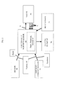
- FIG. 1 is a schematic view of a turbine starter
- FIG. 2 is a schematic diagram of an electrically powered motor to control at least a valve of the turbine starter.
- a turbine starter 10 is provided and includes a turbine section 20, a supply duct 30, a valve 40, a sensor 50 and an electrically powered motor 60.
- the turbine section 20 includes a turbine that rotates about a rotor centerline to drive rotation of a shaft 25, which is coupled to an engine gearbox at a front end of the turbine section 20.
- the supply duct 30 is disposed upstream from and in fluid communication with the turbine section 20 and includes a peripheral wall 31 that is formed to define an air flow pathway 32 by which air is provided from an inlet to the turbine section 20.
- the air may be supplied from various sources, including, but not limited to, an aircraft air supply.
- the supply duct 30 further includes a mounting flange 34, by which the supply duct 30 and the turbine section 20 are fluidly coupled to one another, and a valve mounting 35 on which the valve 40 is mounted.
- the valve 40 is therefore disposed within the supply duct 30 and along the air flow pathway 32. In this position, the valve 40 may be opened and closed to thereby modulate an amount of the air that is permitted to flow to the turbine section 20. That is, if the flow of the air needs to be reduced, the valve 40 may be wholly or partially closed and, if the flow of the air needs to be increased, the valve 40 may be wholly or partially opened.
- the valve 40 may be any type of valve including, but not limited to, a butterfly valve or a similar type of valve. In addition, as will be discussed below, the valve 40 may be controllable in accordance with multiple types of control algorithms.
- the sensor 50 detects a characteristic of the air to be supplied to the turbine section.
- the sensor 50 may include a pressure sensor and, in some embodiments, may include a static pressure sensor, a dynamic pressure sensor and/or a dynamic total pressure sensor with, in accordance with further embodiments, a piezoresistive sensor diaphragm.
- the sensor 50 may be disposed in one more of various locations, such as a location upstream from the valve 40, a location downstream from the valve 40 and upstream from the turbine section 20 and/or a location downstream from or at the turbine section 20 where the sensor may include an aircraft ambient pressure sensor 51 as an example.
- the sensor 50 may be provided as a single component at any of these locations or as multiple sensors 50 at these locations.
- the sensor 50 may be provided as multiple sensors 50 at each of these locations. That is there may be one or more sensors 50 at one or more of the locations.
- the senor 50 may be disposed downstream from the valve 40 and upstream from the turbine section 20 with the aircraft ambient sensor 51 provided downstream from or at the turbine section 20.
- the aircraft ambient pressure sensor 51 may be a temperature/pressure sensor already provided on the aircraft such that an additional component is not necessary.
- the electrically powered motor 60 may include a motor, a logic controller and motor control and is coupled to and disposed in signal communication with the valve 40.
- the electrically powered motor 60 is further coupled to and disposed in signal communication with the sensor 50.
- the electrically powered motor 60 is configured to control the valve 40 to open and close in order to cause the valve 40 to modulate the amount of the air permitted to flow to the turbine section 20 in accordance with at least the detected characteristic.
- the electrically powered motor 60 may receive input data reflective of air pressure at the supply duct inlet, Pinlet, and ambient pressure, Pambient, for the turbine section 20 output.
- the ambient pressure, Pambient may be determined by the sensor 50, aircraft data, engine data and/or a delta pressure transducer disposed across the turbine. In this way, turbine pressure downstream from the turbine section 20 and upstream from the turbine section 20 can be employed to determine a turbine pressure drop across the turbine section 20 for which turbine starter torque and speed can be controlled so that the turbine section 20 can be operated within normal parameters for the current condition.
- the electrically powered motor 60 could output a control signal, S, to the valve 40 that instructs or causes the valve 40 to open to thereby allow more air to pass to the turbine section 20.
- the appropriate turbine pressure drop which is associated with the air pressure at the supply duct inlet, Pinlet, and the ambient pressure, Pambient, and which may be regarded as a target pressure, could be achieved within a predefined response period.
- the electrically powered motor 60 could also close the valve 40 in a similar manner if the air pressure at the supply duct inlet, Pinlet, is determined to be too high relative to the ambient pressure, Pambient.
- the electrically powered motor 60 may operate according to a single control channel as described above or with multiple control channels with one or more being a feedback control channel, C, defined between for example the valve 40 and the electrically powered motor 60.
- a position of the valve 40 can be adjusted in real-time based upon continually measured changes in the detected characteristic and the observed efficiency of the valve 40 at particular positions. That is, if it is observed that valve 40 closure is not sufficient or is not occurring rapidly enough in order to decrease air supply to the turbine section 20 by the necessary amount, the electrically powered motor 60 could adjust valve 40 position or could instruct the valve 40 to close more rapidly.
- the electrically powered motor 60 may be formed, for example, as a 28 volt motor that derives its power supply from an aircraft power supply.
- the electrically powered motor 60 may be a brushless motor, a permanent magnet motor or any similar type of motor.
- the turbine starter may further include a heating element 70 and a heat sensor 71 disposed on or proximate to the valve 40.
- the heating element 70 may be a resistive element or, more particularly, a heater operably coupled to and controlled by the controller of the electrically powered motor 60. This allows a temperature or a frozen state of a valve 40 to be detected and communicated by the heat sensor 71 and further allows the frozen valve 40 to be heated and unfrozen in accordance with control of the heating element 70 by the electrically powered motor 60.
- the unfrozen valve 40 can be operated thereby without the energy loss of a constant leak when not operating or preheating.
- the heating element 70 and the heat sensor 71 allows for a use of a lower power-rated electrically powered motor 60 than would otherwise be possible.
Landscapes
- Engineering & Computer Science (AREA)
- Chemical & Material Sciences (AREA)
- Combustion & Propulsion (AREA)
- Mechanical Engineering (AREA)
- General Engineering & Computer Science (AREA)
- Control Of Turbines (AREA)
- Details Of Valves (AREA)
Abstract
Description
- The subject matter disclosed herein relates to a valve for a turbine starter.
- Turbine starters include turbines that require a supply of air to operate properly. This air supply is provided via duct work upstream from the turbine through which an air flow pathway is defined. A valve is normally disposed along this pathway for modulating an amount of the air flow permitted to proceed to the turbine. Where more air flow is required, the valve is opened and, where it is necessary to limit the flow, the valve is closed.
- The valves for modem turbine starters are typically controlled by pneumatic controllers. These controllers operate on water saturated and contaminated air in icing conditions, which can result in poor reliability and high warranty costs. In addition, the pneumatic actuation of the valve is typically oversized to overcome the icing problem. This increases the weight of the turbine starter and, in an airplane, for example, the added weight may be particularly troublesome.
- According to an aspect of the invention, a turbine starter is provided and includes a valve to modulate an amount of air permitted to flow to a turbine section, a sensor to detect a characteristic of the air at locations defined between the valve and the turbine section and downstream from the turbine section and an electrically powered motor coupled to the valve and the sensor to control the valve to modulate the amount of the air permitted to flow to the turbine section in accordance with the detected characteristic.
- According to another aspect of the invention, a turbine starter is provided and includes a turbine section, a supply duct formed to define an air flow pathway by which air is provided to the turbine section, a valve disposed within the supply duct along the air flow pathway to modulate an amount of the air permitted to flow to the turbine section, a sensor to detect a characteristic of the air at a location defined between the valve and the turbine section and a location defined downstream from the turbine section and an electrically powered motor coupled to the valve and the sensor to control the valve to modulate the amount of the air permitted to flow to the turbine section in accordance with the detected characteristic.
- According to yet another aspect of the invention, a turbine starter is provided and includes a turbine section, a supply duct formed to define an air flow pathway by which air is provided to the turbine section, a valve disposed within the supply duct along the air flow pathway to modulate an amount of the air permitted to flow to the turbine section, a static pressure sensor disposed downstream from the valve and upstream from the turbine section to detect a pressure of the air upstream from the turbine section, an ambient pressure sensor disposed downstream from or at the turbine section to detect an ambient pressure of the air and an electrically powered motor coupled to the valve, the sensor and the ambient pressure sensor to control the valve to modulate the amount of the air permitted to flow to the turbine section in accordance with a pressure drop across the turbine section, which is associated with the detected pressure upstream from the turbine section and the detected ambient pressure, and in accordance with feedback control.
- These and other advantages and features will become more apparent from the following description taken in conjunction with the drawings.
- The subject matter which is regarded as the invention is particularly pointed out and distinctly claimed in the claims at the conclusion of the specification. The foregoing and other features, and advantages of the invention are apparent from the following detailed description taken in conjunction with the accompanying drawings in which:
-
FIG. 1 is a schematic view of a turbine starter; and -
FIG. 2 is a schematic diagram of an electrically powered motor to control at least a valve of the turbine starter. - The detailed description explains embodiments of the invention, together with advantages and features, by way of example with reference to the drawings.
- With reference to
FIGS. 1 and2 , aturbine starter 10 is provided and includes aturbine section 20, asupply duct 30, avalve 40, asensor 50 and an electrically poweredmotor 60. Theturbine section 20 includes a turbine that rotates about a rotor centerline to drive rotation of ashaft 25, which is coupled to an engine gearbox at a front end of theturbine section 20. Thesupply duct 30 is disposed upstream from and in fluid communication with theturbine section 20 and includes aperipheral wall 31 that is formed to define anair flow pathway 32 by which air is provided from an inlet to theturbine section 20. The air may be supplied from various sources, including, but not limited to, an aircraft air supply. - The
supply duct 30 further includes amounting flange 34, by which thesupply duct 30 and theturbine section 20 are fluidly coupled to one another, and a valve mounting 35 on which thevalve 40 is mounted. Thevalve 40 is therefore disposed within thesupply duct 30 and along theair flow pathway 32. In this position, thevalve 40 may be opened and closed to thereby modulate an amount of the air that is permitted to flow to theturbine section 20. That is, if the flow of the air needs to be reduced, thevalve 40 may be wholly or partially closed and, if the flow of the air needs to be increased, thevalve 40 may be wholly or partially opened. Thevalve 40 may be any type of valve including, but not limited to, a butterfly valve or a similar type of valve. In addition, as will be discussed below, thevalve 40 may be controllable in accordance with multiple types of control algorithms. - The
sensor 50 detects a characteristic of the air to be supplied to the turbine section. Thesensor 50 may include a pressure sensor and, in some embodiments, may include a static pressure sensor, a dynamic pressure sensor and/or a dynamic total pressure sensor with, in accordance with further embodiments, a piezoresistive sensor diaphragm. Thesensor 50 may be disposed in one more of various locations, such as a location upstream from thevalve 40, a location downstream from thevalve 40 and upstream from theturbine section 20 and/or a location downstream from or at theturbine section 20 where the sensor may include an aircraftambient pressure sensor 51 as an example. Thesensor 50 may be provided as a single component at any of these locations or asmultiple sensors 50 at these locations. Moreover, thesensor 50 may be provided asmultiple sensors 50 at each of these locations. That is there may be one ormore sensors 50 at one or more of the locations. - In accordance with further embodiments, where the
turbine starter 10 is provided for use with an aircraft, thesensor 50 may be disposed downstream from thevalve 40 and upstream from theturbine section 20 with the aircraftambient sensor 51 provided downstream from or at theturbine section 20. Here, the aircraftambient pressure sensor 51 may be a temperature/pressure sensor already provided on the aircraft such that an additional component is not necessary. - The electrically powered
motor 60 may include a motor, a logic controller and motor control and is coupled to and disposed in signal communication with thevalve 40. The electrically poweredmotor 60 is further coupled to and disposed in signal communication with thesensor 50. As such, the electrically poweredmotor 60 is configured to control thevalve 40 to open and close in order to cause thevalve 40 to modulate the amount of the air permitted to flow to theturbine section 20 in accordance with at least the detected characteristic. - That is, where the detected characteristic is a pressure of the air, the electrically powered
motor 60 may receive input data reflective of air pressure at the supply duct inlet, Pinlet, and ambient pressure, Pambient, for theturbine section 20 output. The ambient pressure, Pambient, may be determined by thesensor 50, aircraft data, engine data and/or a delta pressure transducer disposed across the turbine. In this way, turbine pressure downstream from theturbine section 20 and upstream from theturbine section 20 can be employed to determine a turbine pressure drop across theturbine section 20 for which turbine starter torque and speed can be controlled so that theturbine section 20 can be operated within normal parameters for the current condition. - If the air pressure at the supply duct inlet, Pinlet, is low relative to the ambient pressure, Pambient, such that the turbine pressure drop is correspondingly low, the electrically powered
motor 60 could output a control signal, S, to thevalve 40 that instructs or causes thevalve 40 to open to thereby allow more air to pass to theturbine section 20. In this way, the appropriate turbine pressure drop, which is associated with the air pressure at the supply duct inlet, Pinlet, and the ambient pressure, Pambient, and which may be regarded as a target pressure, could be achieved within a predefined response period. By contrast, the electrically poweredmotor 60 could also close thevalve 40 in a similar manner if the air pressure at the supply duct inlet, Pinlet, is determined to be too high relative to the ambient pressure, Pambient. - The electrically powered
motor 60 may operate according to a single control channel as described above or with multiple control channels with one or more being a feedback control channel, C, defined between for example thevalve 40 and the electrically poweredmotor 60. With the feedback control channel, C, a position of thevalve 40 can be adjusted in real-time based upon continually measured changes in the detected characteristic and the observed efficiency of thevalve 40 at particular positions. That is, if it is observed thatvalve 40 closure is not sufficient or is not occurring rapidly enough in order to decrease air supply to theturbine section 20 by the necessary amount, the electrically poweredmotor 60 could adjustvalve 40 position or could instruct thevalve 40 to close more rapidly. - The electrically powered
motor 60 may be formed, for example, as a 28 volt motor that derives its power supply from an aircraft power supply. The electrically poweredmotor 60 may be a brushless motor, a permanent magnet motor or any similar type of motor. - The turbine starter may further include a
heating element 70 and aheat sensor 71 disposed on or proximate to thevalve 40. Theheating element 70 may be a resistive element or, more particularly, a heater operably coupled to and controlled by the controller of the electrically poweredmotor 60. This allows a temperature or a frozen state of avalve 40 to be detected and communicated by theheat sensor 71 and further allows the frozenvalve 40 to be heated and unfrozen in accordance with control of theheating element 70 by the electrically poweredmotor 60. The unfrozenvalve 40 can be operated thereby without the energy loss of a constant leak when not operating or preheating. Theheating element 70 and theheat sensor 71 allows for a use of a lower power-rated electrically poweredmotor 60 than would otherwise be possible. - While the invention has been described in detail in connection with only a limited number of embodiments, it should be readily understood that the invention is not limited to such disclosed embodiments. Rather, the invention can be modified to incorporate any number of variations, alterations, substitutions or equivalent arrangements not heretofore described, but which are commensurate with the scope of the invention, which is defined by the claims. Additionally, while various embodiments of the invention have been described, it is to be understood that aspects of the invention may include only some of the described embodiments. Accordingly, the invention is not to be seen as limited by the foregoing description, but is only limited by the scope of the appended claims.
Claims (11)
- A turbine starter, comprising:a turbine section (20);a supply duct (30) formed to define an air flow pathway by which air is provided to the turbine section;a valve (40) disposed within the supply duct along the air flow pathway to modulate an amount of the air permitted to flow to the turbine section;a sensor (50,51) to detect a characteristic of the air at a location defined between the valve and the turbine section and at a location defined downstream from the turbine section; andan electrically powered motor (60) coupled to the valve and the sensor to control the valve to modulate the amount of the air permitted to flow to the turbine section in accordance with the detected characteristic.
- The turbine starter according to claim 1, wherein the supply duct comprises a valve mounting upstream from the turbine section on which the valve is mounted.
- The turbine starter according to claim 1 or 2, wherein the valve comprises a butterfly valve.
- The turbine starter according to claim 1, 2 or 3, wherein the electrically powered motor controls the valve in accordance with the detected characteristic and a target value for the characteristic.
- The turbine starter according to claim 4, wherein the electrically powered motor controls the valve in accordance with the detected characteristic, a target value for the characteristic and feedback control.
- The turbine starter according to any preceding claim, wherein the sensor comprises static pressure sensor, dynamic pressure sensor, dynamic total pressure sensor and/or an aircraft ambient pressure sensor (51).
- The turbine starter according to any of claims 1 to 5, wherein the sensor comprises a pressure sensor (50) disposed between the valve and the turbine section.
- The turbine starter according to claim 7, wherein the pressure sensor comprises a static pressure sensor, a dynamic pressure sensor and/or a dynamic total pressure sensor.
- The turbine starter according to claim 7 or 8, wherein the sensor further comprises an aircraft ambient pressure sensor (51) disposed downstream from or at the turbine section.
- The turbine starter according to any of claims 1 to 5, wherein:the sensor comprises a static pressure sensor (50) disposed downstream from the valve and upstream from the turbine section to detect a pressure of the air upstream from the turbine section; and an ambient pressure sensor (51) disposed downstream from or at the turbine section to detect an ambient pressure of the air; andthe electrically powered motor is coupled to the valve, the static pressure sensor and the ambient pressure sensor to control the valve to modulate the amount of the air permitted to flow to the turbine section in accordance with a pressure drop across the turbine section, which is associated with the detected pressure upstream from the turbine section and the detected ambient pressure, and in accordance with feedback control.
- The turbine starter according to claim 10, further comprising:a heating element (70) disposed on the valve; anda heat sensor (71) disposed on the valve to detect a temperature of the valve.
Applications Claiming Priority (1)
| Application Number | Priority Date | Filing Date | Title |
|---|---|---|---|
| US12/888,147 US8667803B2 (en) | 2010-09-22 | 2010-09-22 | Turbine starter valve |
Publications (3)
| Publication Number | Publication Date |
|---|---|
| EP2434130A2 true EP2434130A2 (en) | 2012-03-28 |
| EP2434130A3 EP2434130A3 (en) | 2015-06-24 |
| EP2434130B1 EP2434130B1 (en) | 2017-07-05 |
Family
ID=44785470
Family Applications (1)
| Application Number | Title | Priority Date | Filing Date |
|---|---|---|---|
| EP11182372.0A Not-in-force EP2434130B1 (en) | 2010-09-22 | 2011-09-22 | Turbine starter valve |
Country Status (2)
| Country | Link |
|---|---|
| US (1) | US8667803B2 (en) |
| EP (1) | EP2434130B1 (en) |
Cited By (3)
| Publication number | Priority date | Publication date | Assignee | Title |
|---|---|---|---|---|
| CN107916997A (en) * | 2016-10-11 | 2018-04-17 | 和谐工业有限责任公司 | Integrated actuating device for aircraft |
| KR20180040110A (en) * | 2016-10-11 | 2018-04-19 | 유니슨 인더스트리즈, 엘엘씨 | Starter issue detection |
| EP3922828A1 (en) * | 2020-06-11 | 2021-12-15 | Honeywell International Inc. | Closed-loop controlled air turbine start system |
Families Citing this family (6)
| Publication number | Priority date | Publication date | Assignee | Title |
|---|---|---|---|---|
| US20170350322A1 (en) * | 2016-06-02 | 2017-12-07 | Hamilton Sundstrand Corporation | Heated starter air valve |
| EP3273016B1 (en) | 2016-07-21 | 2020-04-01 | United Technologies Corporation | Multi-engine coordination during gas turbine engine motoring |
| US10618666B2 (en) | 2016-07-21 | 2020-04-14 | United Technologies Corporation | Pre-start motoring synchronization for multiple engines |
| EP3273006B1 (en) * | 2016-07-21 | 2019-07-03 | United Technologies Corporation | Alternating starter use during multi-engine motoring |
| US20180209295A1 (en) * | 2016-10-11 | 2018-07-26 | General Electric Company | Starter controller |
| US10711701B2 (en) * | 2017-06-06 | 2020-07-14 | Hamilton Sunstrand Corporation | Manual bowed rotor and full override |
Family Cites Families (22)
| Publication number | Priority date | Publication date | Assignee | Title |
|---|---|---|---|---|
| US2750737A (en) * | 1953-04-20 | 1956-06-19 | Leonard P Leigh | Deicing apparatus for jet engines |
| GB797025A (en) * | 1955-03-24 | 1958-06-25 | Bendix Aviat Corp | Air pressure regulating and shut-off valve |
| US3668013A (en) | 1969-04-21 | 1972-06-06 | United Aircraft Corp | Fuel cell system with pneumatic fuel flow control |
| US3769998A (en) * | 1971-10-07 | 1973-11-06 | Garrett Corp | Regulator and shutoff valve |
| US3795145A (en) * | 1972-03-23 | 1974-03-05 | Sperry Rand Corp | Variable throat venturi airspeed sensor |
| US4006634A (en) * | 1975-09-17 | 1977-02-08 | National Semiconductor Corporation | Flow meter |
| US4339916A (en) | 1978-03-13 | 1982-07-20 | The Garrett Corporation | Pneumatic starter overtemperature control |
| US4335738A (en) * | 1979-06-19 | 1982-06-22 | Nicholas Nassir | Butterfly valve |
| US4506690A (en) | 1979-10-15 | 1985-03-26 | The Garrett Corporation | Pressure regulator system |
| US4617958A (en) * | 1985-07-25 | 1986-10-21 | Sundstrand Corporation | Control valve |
| US4702273A (en) * | 1986-03-07 | 1987-10-27 | Parker Hannifin Corporation | Electrically controlled starter air valve |
| FR2607189B1 (en) * | 1986-11-20 | 1990-05-04 | Snecma | DEVICE FOR CONTROLLING A STARTING VALVE OF AN AVIATION TURBOMACHINE |
| US4980622A (en) | 1988-08-29 | 1990-12-25 | United Technologies Corporation | Actuator two-fault tolerance apparatus |
| US5237815A (en) | 1991-02-19 | 1993-08-24 | Sundstrand Corporation | Control of a hydraulic start system |
| US5315817A (en) * | 1992-08-17 | 1994-05-31 | United Technologies Corporation | Control system for preventing crash engagement of a ratchet and pawl clutch during restart of a turbine engine |
| US5463865A (en) * | 1993-09-30 | 1995-11-07 | General Electric Company | Starter air valve position pressure transducer |
| US6079210A (en) * | 1998-07-16 | 2000-06-27 | Woodward Governor Company | Continuously variable electrically actuated flow control valve for high temperature applications |
| US6684898B2 (en) * | 2001-09-27 | 2004-02-03 | Honeywell International Inc. | Dual actuator air turbine starter valve |
| US6694746B2 (en) * | 2002-02-06 | 2004-02-24 | Honeywell International, Inc. | Micro volume actuator for an air turbine starter |
| US7335999B2 (en) | 2004-06-15 | 2008-02-26 | Honeywell International, Inc. | Fluid actuated rotating device including a low power generator |
| US7555905B2 (en) | 2006-03-28 | 2009-07-07 | United Technologies Corporation | Self-actuating bleed valve for gas turbine engine |
| US7690188B2 (en) | 2007-03-02 | 2010-04-06 | United Technologies Corporation | Combination engines for aircraft |
-
2010
- 2010-09-22 US US12/888,147 patent/US8667803B2/en not_active Expired - Fee Related
-
2011
- 2011-09-22 EP EP11182372.0A patent/EP2434130B1/en not_active Not-in-force
Non-Patent Citations (1)
| Title |
|---|
| None |
Cited By (7)
| Publication number | Priority date | Publication date | Assignee | Title |
|---|---|---|---|---|
| CN107916997A (en) * | 2016-10-11 | 2018-04-17 | 和谐工业有限责任公司 | Integrated actuating device for aircraft |
| EP3309373A1 (en) * | 2016-10-11 | 2018-04-18 | Unison Industries LLC | Integrated starter for aerial vehicle |
| KR20180040110A (en) * | 2016-10-11 | 2018-04-19 | 유니슨 인더스트리즈, 엘엘씨 | Starter issue detection |
| JP2018062935A (en) * | 2016-10-11 | 2018-04-19 | ユニゾン・インダストリーズ,エルエルシー | Integrated starter for aircraft |
| US10598095B2 (en) | 2016-10-11 | 2020-03-24 | Unison Industries, Llc | Integrated starter for aerial vehicle |
| CN107916997B (en) * | 2016-10-11 | 2020-05-19 | 和谐工业有限责任公司 | Integrated starter for aircraft |
| EP3922828A1 (en) * | 2020-06-11 | 2021-12-15 | Honeywell International Inc. | Closed-loop controlled air turbine start system |
Also Published As
| Publication number | Publication date |
|---|---|
| US20120067062A1 (en) | 2012-03-22 |
| EP2434130B1 (en) | 2017-07-05 |
| EP2434130A3 (en) | 2015-06-24 |
| US8667803B2 (en) | 2014-03-11 |
Similar Documents
| Publication | Publication Date | Title |
|---|---|---|
| US8667803B2 (en) | Turbine starter valve | |
| EP2492473B1 (en) | Fuel system | |
| US7895819B2 (en) | Assistance and emergency backup for the electrical drive of a fuel pump in a turbine engine | |
| US8291886B2 (en) | Actuator flow compensated direct metering fuel control system and method | |
| US9512784B2 (en) | Free gas turbine with constant temperature-corrected gas generator speed | |
| US7762080B2 (en) | Fuel metering pump calibration method | |
| EP3318726B1 (en) | System and method for controlling dual starter air valve | |
| RU2007146439A (en) | FUEL DEVICE FOR GAS-TURBINE ENGINE WITH ADJUSTABLE FUEL CONSUMPTION | |
| US11332234B2 (en) | Control system and method for an electro-hydraulic servo-actuator, in particular of a turbopropeller engine | |
| EP3444464B1 (en) | System and method for rotating a gas turbine engine during a motoring cycle | |
| CN109312665B (en) | Fuel delivery system and method for gas turbine engine | |
| EP3683425A1 (en) | Pressure regulating starter valve | |
| EP3583305B1 (en) | Systems including an electrically assisted turbocharger and methods of using the same | |
| US8590288B2 (en) | Fan control apparatus | |
| JPWO2022091273A5 (en) | ||
| US20120240878A1 (en) | Internal combustion engine with fan system | |
| EP3395688B1 (en) | Configurable high rate closed loop smart valve control | |
| CN113825897B (en) | Turbine comprising a deicing system for an upstream cone and related method | |
| US11397123B2 (en) | Engine with valve device and test method | |
| EP2489859A1 (en) | Free gas turbine with constant temperature-corrected gas generator speed |
Legal Events
| Date | Code | Title | Description |
|---|---|---|---|
| PUAI | Public reference made under article 153(3) epc to a published international application that has entered the european phase |
Free format text: ORIGINAL CODE: 0009012 |
|
| AK | Designated contracting states |
Kind code of ref document: A2 Designated state(s): AL AT BE BG CH CY CZ DE DK EE ES FI FR GB GR HR HU IE IS IT LI LT LU LV MC MK MT NL NO PL PT RO RS SE SI SK SM TR |
|
| AX | Request for extension of the european patent |
Extension state: BA ME |
|
| PUAL | Search report despatched |
Free format text: ORIGINAL CODE: 0009013 |
|
| AK | Designated contracting states |
Kind code of ref document: A3 Designated state(s): AL AT BE BG CH CY CZ DE DK EE ES FI FR GB GR HR HU IE IS IT LI LT LU LV MC MK MT NL NO PL PT RO RS SE SI SK SM TR |
|
| AX | Request for extension of the european patent |
Extension state: BA ME |
|
| RIC1 | Information provided on ipc code assigned before grant |
Ipc: G05D 16/20 20060101ALI20150521BHEP Ipc: F16K 31/04 20060101ALI20150521BHEP Ipc: F02C 7/26 20060101AFI20150521BHEP Ipc: F02C 7/277 20060101ALI20150521BHEP |
|
| 17P | Request for examination filed |
Effective date: 20151223 |
|
| RBV | Designated contracting states (corrected) |
Designated state(s): AL AT BE BG CH CY CZ DE DK EE ES FI FR GB GR HR HU IE IS IT LI LT LU LV MC MK MT NL NO PL PT RO RS SE SI SK SM TR |
|
| RIC1 | Information provided on ipc code assigned before grant |
Ipc: G05D 16/20 20060101ALI20161214BHEP Ipc: F02C 7/277 20060101ALI20161214BHEP Ipc: F16K 31/04 20060101ALI20161214BHEP Ipc: F02C 7/26 20060101AFI20161214BHEP |
|
| GRAP | Despatch of communication of intention to grant a patent |
Free format text: ORIGINAL CODE: EPIDOSNIGR1 |
|
| INTG | Intention to grant announced |
Effective date: 20170124 |
|
| GRAS | Grant fee paid |
Free format text: ORIGINAL CODE: EPIDOSNIGR3 |
|
| GRAA | (expected) grant |
Free format text: ORIGINAL CODE: 0009210 |
|
| AK | Designated contracting states |
Kind code of ref document: B1 Designated state(s): AL AT BE BG CH CY CZ DE DK EE ES FI FR GB GR HR HU IE IS IT LI LT LU LV MC MK MT NL NO PL PT RO RS SE SI SK SM TR |
|
| REG | Reference to a national code |
Ref country code: GB Ref legal event code: FG4D |
|
| REG | Reference to a national code |
Ref country code: CH Ref legal event code: EP |
|
| REG | Reference to a national code |
Ref country code: AT Ref legal event code: REF Ref document number: 906783 Country of ref document: AT Kind code of ref document: T Effective date: 20170715 |
|
| REG | Reference to a national code |
Ref country code: IE Ref legal event code: FG4D |
|
| REG | Reference to a national code |
Ref country code: DE Ref legal event code: R096 Ref document number: 602011039269 Country of ref document: DE |
|
| REG | Reference to a national code |
Ref country code: FR Ref legal event code: PLFP Year of fee payment: 7 |
|
| REG | Reference to a national code |
Ref country code: NL Ref legal event code: MP Effective date: 20170705 |
|
| REG | Reference to a national code |
Ref country code: AT Ref legal event code: MK05 Ref document number: 906783 Country of ref document: AT Kind code of ref document: T Effective date: 20170705 |
|
| REG | Reference to a national code |
Ref country code: LT Ref legal event code: MG4D |
|
| PG25 | Lapsed in a contracting state [announced via postgrant information from national office to epo] |
Ref country code: NL Free format text: LAPSE BECAUSE OF FAILURE TO SUBMIT A TRANSLATION OF THE DESCRIPTION OR TO PAY THE FEE WITHIN THE PRESCRIBED TIME-LIMIT Effective date: 20170705 Ref country code: AT Free format text: LAPSE BECAUSE OF FAILURE TO SUBMIT A TRANSLATION OF THE DESCRIPTION OR TO PAY THE FEE WITHIN THE PRESCRIBED TIME-LIMIT Effective date: 20170705 Ref country code: LT Free format text: LAPSE BECAUSE OF FAILURE TO SUBMIT A TRANSLATION OF THE DESCRIPTION OR TO PAY THE FEE WITHIN THE PRESCRIBED TIME-LIMIT Effective date: 20170705 Ref country code: NO Free format text: LAPSE BECAUSE OF FAILURE TO SUBMIT A TRANSLATION OF THE DESCRIPTION OR TO PAY THE FEE WITHIN THE PRESCRIBED TIME-LIMIT Effective date: 20171005 Ref country code: HR Free format text: LAPSE BECAUSE OF FAILURE TO SUBMIT A TRANSLATION OF THE DESCRIPTION OR TO PAY THE FEE WITHIN THE PRESCRIBED TIME-LIMIT Effective date: 20170705 Ref country code: FI Free format text: LAPSE BECAUSE OF FAILURE TO SUBMIT A TRANSLATION OF THE DESCRIPTION OR TO PAY THE FEE WITHIN THE PRESCRIBED TIME-LIMIT Effective date: 20170705 Ref country code: SE Free format text: LAPSE BECAUSE OF FAILURE TO SUBMIT A TRANSLATION OF THE DESCRIPTION OR TO PAY THE FEE WITHIN THE PRESCRIBED TIME-LIMIT Effective date: 20170705 |
|
| PG25 | Lapsed in a contracting state [announced via postgrant information from national office to epo] |
Ref country code: PL Free format text: LAPSE BECAUSE OF FAILURE TO SUBMIT A TRANSLATION OF THE DESCRIPTION OR TO PAY THE FEE WITHIN THE PRESCRIBED TIME-LIMIT Effective date: 20170705 Ref country code: ES Free format text: LAPSE BECAUSE OF FAILURE TO SUBMIT A TRANSLATION OF THE DESCRIPTION OR TO PAY THE FEE WITHIN THE PRESCRIBED TIME-LIMIT Effective date: 20170705 Ref country code: IS Free format text: LAPSE BECAUSE OF FAILURE TO SUBMIT A TRANSLATION OF THE DESCRIPTION OR TO PAY THE FEE WITHIN THE PRESCRIBED TIME-LIMIT Effective date: 20171105 Ref country code: RS Free format text: LAPSE BECAUSE OF FAILURE TO SUBMIT A TRANSLATION OF THE DESCRIPTION OR TO PAY THE FEE WITHIN THE PRESCRIBED TIME-LIMIT Effective date: 20170705 Ref country code: GR Free format text: LAPSE BECAUSE OF FAILURE TO SUBMIT A TRANSLATION OF THE DESCRIPTION OR TO PAY THE FEE WITHIN THE PRESCRIBED TIME-LIMIT Effective date: 20171006 Ref country code: LV Free format text: LAPSE BECAUSE OF FAILURE TO SUBMIT A TRANSLATION OF THE DESCRIPTION OR TO PAY THE FEE WITHIN THE PRESCRIBED TIME-LIMIT Effective date: 20170705 Ref country code: BG Free format text: LAPSE BECAUSE OF FAILURE TO SUBMIT A TRANSLATION OF THE DESCRIPTION OR TO PAY THE FEE WITHIN THE PRESCRIBED TIME-LIMIT Effective date: 20171005 |
|
| REG | Reference to a national code |
Ref country code: DE Ref legal event code: R097 Ref document number: 602011039269 Country of ref document: DE |
|
| PG25 | Lapsed in a contracting state [announced via postgrant information from national office to epo] |
Ref country code: CZ Free format text: LAPSE BECAUSE OF FAILURE TO SUBMIT A TRANSLATION OF THE DESCRIPTION OR TO PAY THE FEE WITHIN THE PRESCRIBED TIME-LIMIT Effective date: 20170705 Ref country code: DK Free format text: LAPSE BECAUSE OF FAILURE TO SUBMIT A TRANSLATION OF THE DESCRIPTION OR TO PAY THE FEE WITHIN THE PRESCRIBED TIME-LIMIT Effective date: 20170705 Ref country code: RO Free format text: LAPSE BECAUSE OF FAILURE TO SUBMIT A TRANSLATION OF THE DESCRIPTION OR TO PAY THE FEE WITHIN THE PRESCRIBED TIME-LIMIT Effective date: 20170705 |
|
| REG | Reference to a national code |
Ref country code: CH Ref legal event code: PL |
|
| PLBE | No opposition filed within time limit |
Free format text: ORIGINAL CODE: 0009261 |
|
| STAA | Information on the status of an ep patent application or granted ep patent |
Free format text: STATUS: NO OPPOSITION FILED WITHIN TIME LIMIT |
|
| PG25 | Lapsed in a contracting state [announced via postgrant information from national office to epo] |
Ref country code: SK Free format text: LAPSE BECAUSE OF FAILURE TO SUBMIT A TRANSLATION OF THE DESCRIPTION OR TO PAY THE FEE WITHIN THE PRESCRIBED TIME-LIMIT Effective date: 20170705 Ref country code: MC Free format text: LAPSE BECAUSE OF FAILURE TO SUBMIT A TRANSLATION OF THE DESCRIPTION OR TO PAY THE FEE WITHIN THE PRESCRIBED TIME-LIMIT Effective date: 20170705 Ref country code: IT Free format text: LAPSE BECAUSE OF FAILURE TO SUBMIT A TRANSLATION OF THE DESCRIPTION OR TO PAY THE FEE WITHIN THE PRESCRIBED TIME-LIMIT Effective date: 20170705 Ref country code: EE Free format text: LAPSE BECAUSE OF FAILURE TO SUBMIT A TRANSLATION OF THE DESCRIPTION OR TO PAY THE FEE WITHIN THE PRESCRIBED TIME-LIMIT Effective date: 20170705 Ref country code: SM Free format text: LAPSE BECAUSE OF FAILURE TO SUBMIT A TRANSLATION OF THE DESCRIPTION OR TO PAY THE FEE WITHIN THE PRESCRIBED TIME-LIMIT Effective date: 20170705 |
|
| 26N | No opposition filed |
Effective date: 20180406 |
|
| REG | Reference to a national code |
Ref country code: IE Ref legal event code: MM4A |
|
| REG | Reference to a national code |
Ref country code: BE Ref legal event code: MM Effective date: 20170930 |
|
| PG25 | Lapsed in a contracting state [announced via postgrant information from national office to epo] |
Ref country code: LU Free format text: LAPSE BECAUSE OF NON-PAYMENT OF DUE FEES Effective date: 20170922 |
|
| PG25 | Lapsed in a contracting state [announced via postgrant information from national office to epo] |
Ref country code: LI Free format text: LAPSE BECAUSE OF NON-PAYMENT OF DUE FEES Effective date: 20170930 Ref country code: CH Free format text: LAPSE BECAUSE OF NON-PAYMENT OF DUE FEES Effective date: 20170930 Ref country code: IE Free format text: LAPSE BECAUSE OF NON-PAYMENT OF DUE FEES Effective date: 20170922 |
|
| REG | Reference to a national code |
Ref country code: FR Ref legal event code: PLFP Year of fee payment: 8 |
|
| PG25 | Lapsed in a contracting state [announced via postgrant information from national office to epo] |
Ref country code: SI Free format text: LAPSE BECAUSE OF FAILURE TO SUBMIT A TRANSLATION OF THE DESCRIPTION OR TO PAY THE FEE WITHIN THE PRESCRIBED TIME-LIMIT Effective date: 20170705 Ref country code: BE Free format text: LAPSE BECAUSE OF NON-PAYMENT OF DUE FEES Effective date: 20170930 |
|
| PG25 | Lapsed in a contracting state [announced via postgrant information from national office to epo] |
Ref country code: MT Free format text: LAPSE BECAUSE OF NON-PAYMENT OF DUE FEES Effective date: 20170922 |
|
| PG25 | Lapsed in a contracting state [announced via postgrant information from national office to epo] |
Ref country code: HU Free format text: LAPSE BECAUSE OF FAILURE TO SUBMIT A TRANSLATION OF THE DESCRIPTION OR TO PAY THE FEE WITHIN THE PRESCRIBED TIME-LIMIT; INVALID AB INITIO Effective date: 20110922 |
|
| PG25 | Lapsed in a contracting state [announced via postgrant information from national office to epo] |
Ref country code: CY Free format text: LAPSE BECAUSE OF NON-PAYMENT OF DUE FEES Effective date: 20170705 |
|
| PG25 | Lapsed in a contracting state [announced via postgrant information from national office to epo] |
Ref country code: MK Free format text: LAPSE BECAUSE OF FAILURE TO SUBMIT A TRANSLATION OF THE DESCRIPTION OR TO PAY THE FEE WITHIN THE PRESCRIBED TIME-LIMIT Effective date: 20170705 |
|
| PG25 | Lapsed in a contracting state [announced via postgrant information from national office to epo] |
Ref country code: TR Free format text: LAPSE BECAUSE OF FAILURE TO SUBMIT A TRANSLATION OF THE DESCRIPTION OR TO PAY THE FEE WITHIN THE PRESCRIBED TIME-LIMIT Effective date: 20170705 |
|
| PG25 | Lapsed in a contracting state [announced via postgrant information from national office to epo] |
Ref country code: PT Free format text: LAPSE BECAUSE OF FAILURE TO SUBMIT A TRANSLATION OF THE DESCRIPTION OR TO PAY THE FEE WITHIN THE PRESCRIBED TIME-LIMIT Effective date: 20170705 |
|
| PG25 | Lapsed in a contracting state [announced via postgrant information from national office to epo] |
Ref country code: AL Free format text: LAPSE BECAUSE OF FAILURE TO SUBMIT A TRANSLATION OF THE DESCRIPTION OR TO PAY THE FEE WITHIN THE PRESCRIBED TIME-LIMIT Effective date: 20170705 |
|
| PGFP | Annual fee paid to national office [announced via postgrant information from national office to epo] |
Ref country code: DE Payment date: 20200819 Year of fee payment: 10 Ref country code: GB Payment date: 20200819 Year of fee payment: 10 Ref country code: FR Payment date: 20200819 Year of fee payment: 10 |
|
| REG | Reference to a national code |
Ref country code: DE Ref legal event code: R082 Ref document number: 602011039269 Country of ref document: DE |
|
| REG | Reference to a national code |
Ref country code: DE Ref legal event code: R119 Ref document number: 602011039269 Country of ref document: DE |
|
| GBPC | Gb: european patent ceased through non-payment of renewal fee |
Effective date: 20210922 |
|
| PG25 | Lapsed in a contracting state [announced via postgrant information from national office to epo] |
Ref country code: GB Free format text: LAPSE BECAUSE OF NON-PAYMENT OF DUE FEES Effective date: 20210922 Ref country code: FR Free format text: LAPSE BECAUSE OF NON-PAYMENT OF DUE FEES Effective date: 20210930 Ref country code: DE Free format text: LAPSE BECAUSE OF NON-PAYMENT OF DUE FEES Effective date: 20220401 |