EP2433832A1 - Child seat - Google Patents
Child seat Download PDFInfo
- Publication number
- EP2433832A1 EP2433832A1 EP10777611A EP10777611A EP2433832A1 EP 2433832 A1 EP2433832 A1 EP 2433832A1 EP 10777611 A EP10777611 A EP 10777611A EP 10777611 A EP10777611 A EP 10777611A EP 2433832 A1 EP2433832 A1 EP 2433832A1
- Authority
- EP
- European Patent Office
- Prior art keywords
- seat
- belt
- child
- child seat
- light
- Prior art date
- Legal status (The legal status is an assumption and is not a legal conclusion. Google has not performed a legal analysis and makes no representation as to the accuracy of the status listed.)
- Granted
Links
Images




Classifications
-
- B—PERFORMING OPERATIONS; TRANSPORTING
- B60—VEHICLES IN GENERAL
- B60N—SEATS SPECIALLY ADAPTED FOR VEHICLES; VEHICLE PASSENGER ACCOMMODATION NOT OTHERWISE PROVIDED FOR
- B60N2/00—Seats specially adapted for vehicles; Arrangement or mounting of seats in vehicles
- B60N2/24—Seats specially adapted for vehicles; Arrangement or mounting of seats in vehicles for particular purposes or particular vehicles
- B60N2/26—Seats specially adapted for vehicles; Arrangement or mounting of seats in vehicles for particular purposes or particular vehicles for children
- B60N2/28—Seats readily mountable on, and dismountable from, existing seats or other parts of the vehicle
- B60N2/2821—Seats readily mountable on, and dismountable from, existing seats or other parts of the vehicle having a seat and a base part
-
- B—PERFORMING OPERATIONS; TRANSPORTING
- B60—VEHICLES IN GENERAL
- B60N—SEATS SPECIALLY ADAPTED FOR VEHICLES; VEHICLE PASSENGER ACCOMMODATION NOT OTHERWISE PROVIDED FOR
- B60N2/00—Seats specially adapted for vehicles; Arrangement or mounting of seats in vehicles
- B60N2/24—Seats specially adapted for vehicles; Arrangement or mounting of seats in vehicles for particular purposes or particular vehicles
- B60N2/26—Seats specially adapted for vehicles; Arrangement or mounting of seats in vehicles for particular purposes or particular vehicles for children
- B60N2/28—Seats readily mountable on, and dismountable from, existing seats or other parts of the vehicle
-
- B—PERFORMING OPERATIONS; TRANSPORTING
- B60—VEHICLES IN GENERAL
- B60N—SEATS SPECIALLY ADAPTED FOR VEHICLES; VEHICLE PASSENGER ACCOMMODATION NOT OTHERWISE PROVIDED FOR
- B60N2/00—Seats specially adapted for vehicles; Arrangement or mounting of seats in vehicles
- B60N2/24—Seats specially adapted for vehicles; Arrangement or mounting of seats in vehicles for particular purposes or particular vehicles
- B60N2/26—Seats specially adapted for vehicles; Arrangement or mounting of seats in vehicles for particular purposes or particular vehicles for children
- B60N2/266—Seats specially adapted for vehicles; Arrangement or mounting of seats in vehicles for particular purposes or particular vehicles for children with detection or alerting means responsive to presence or absence of children; with detection or alerting means responsive to improper locking or installation of the child seats or parts thereof
- B60N2/271—Seats specially adapted for vehicles; Arrangement or mounting of seats in vehicles for particular purposes or particular vehicles for children with detection or alerting means responsive to presence or absence of children; with detection or alerting means responsive to improper locking or installation of the child seats or parts thereof detecting or alerting means responsive to securing the child in the seat
- B60N2/272—Buckle lock sensors for child seat safety belts
-
- A—HUMAN NECESSITIES
- A47—FURNITURE; DOMESTIC ARTICLES OR APPLIANCES; COFFEE MILLS; SPICE MILLS; SUCTION CLEANERS IN GENERAL
- A47C—CHAIRS; SOFAS; BEDS
- A47C7/00—Parts, details, or accessories of chairs or stools
- A47C7/62—Accessories for chairs
- A47C7/72—Adaptations for incorporating lamps, radio sets, bars, telephones, ventilation, heating or cooling arrangements or the like
-
- B—PERFORMING OPERATIONS; TRANSPORTING
- B60—VEHICLES IN GENERAL
- B60N—SEATS SPECIALLY ADAPTED FOR VEHICLES; VEHICLE PASSENGER ACCOMMODATION NOT OTHERWISE PROVIDED FOR
- B60N2/00—Seats specially adapted for vehicles; Arrangement or mounting of seats in vehicles
- B60N2/24—Seats specially adapted for vehicles; Arrangement or mounting of seats in vehicles for particular purposes or particular vehicles
- B60N2/26—Seats specially adapted for vehicles; Arrangement or mounting of seats in vehicles for particular purposes or particular vehicles for children
- B60N2/266—Seats specially adapted for vehicles; Arrangement or mounting of seats in vehicles for particular purposes or particular vehicles for children with detection or alerting means responsive to presence or absence of children; with detection or alerting means responsive to improper locking or installation of the child seats or parts thereof
- B60N2/267—Seats specially adapted for vehicles; Arrangement or mounting of seats in vehicles for particular purposes or particular vehicles for children with detection or alerting means responsive to presence or absence of children; with detection or alerting means responsive to improper locking or installation of the child seats or parts thereof alerting means responsive to presence or absence of children
-
- B—PERFORMING OPERATIONS; TRANSPORTING
- B60—VEHICLES IN GENERAL
- B60N—SEATS SPECIALLY ADAPTED FOR VEHICLES; VEHICLE PASSENGER ACCOMMODATION NOT OTHERWISE PROVIDED FOR
- B60N2/00—Seats specially adapted for vehicles; Arrangement or mounting of seats in vehicles
- B60N2/24—Seats specially adapted for vehicles; Arrangement or mounting of seats in vehicles for particular purposes or particular vehicles
- B60N2/26—Seats specially adapted for vehicles; Arrangement or mounting of seats in vehicles for particular purposes or particular vehicles for children
- B60N2/28—Seats readily mountable on, and dismountable from, existing seats or other parts of the vehicle
- B60N2/2803—Adaptations for seat belts
- B60N2/2806—Adaptations for seat belts for securing the child seat to the vehicle
-
- B—PERFORMING OPERATIONS; TRANSPORTING
- B60—VEHICLES IN GENERAL
- B60N—SEATS SPECIALLY ADAPTED FOR VEHICLES; VEHICLE PASSENGER ACCOMMODATION NOT OTHERWISE PROVIDED FOR
- B60N2/00—Seats specially adapted for vehicles; Arrangement or mounting of seats in vehicles
- B60N2/24—Seats specially adapted for vehicles; Arrangement or mounting of seats in vehicles for particular purposes or particular vehicles
- B60N2/26—Seats specially adapted for vehicles; Arrangement or mounting of seats in vehicles for particular purposes or particular vehicles for children
- B60N2/28—Seats readily mountable on, and dismountable from, existing seats or other parts of the vehicle
- B60N2/2857—Seats readily mountable on, and dismountable from, existing seats or other parts of the vehicle characterised by the peculiar orientation of the child
- B60N2/286—Seats readily mountable on, and dismountable from, existing seats or other parts of the vehicle characterised by the peculiar orientation of the child forward facing
-
- B—PERFORMING OPERATIONS; TRANSPORTING
- B60—VEHICLES IN GENERAL
- B60N—SEATS SPECIALLY ADAPTED FOR VEHICLES; VEHICLE PASSENGER ACCOMMODATION NOT OTHERWISE PROVIDED FOR
- B60N2/00—Seats specially adapted for vehicles; Arrangement or mounting of seats in vehicles
- B60N2/24—Seats specially adapted for vehicles; Arrangement or mounting of seats in vehicles for particular purposes or particular vehicles
- B60N2/26—Seats specially adapted for vehicles; Arrangement or mounting of seats in vehicles for particular purposes or particular vehicles for children
- B60N2/28—Seats readily mountable on, and dismountable from, existing seats or other parts of the vehicle
- B60N2/2857—Seats readily mountable on, and dismountable from, existing seats or other parts of the vehicle characterised by the peculiar orientation of the child
- B60N2/2863—Seats readily mountable on, and dismountable from, existing seats or other parts of the vehicle characterised by the peculiar orientation of the child backward facing
-
- B—PERFORMING OPERATIONS; TRANSPORTING
- B60—VEHICLES IN GENERAL
- B60N—SEATS SPECIALLY ADAPTED FOR VEHICLES; VEHICLE PASSENGER ACCOMMODATION NOT OTHERWISE PROVIDED FOR
- B60N2/00—Seats specially adapted for vehicles; Arrangement or mounting of seats in vehicles
- B60N2/24—Seats specially adapted for vehicles; Arrangement or mounting of seats in vehicles for particular purposes or particular vehicles
- B60N2/26—Seats specially adapted for vehicles; Arrangement or mounting of seats in vehicles for particular purposes or particular vehicles for children
- B60N2/28—Seats readily mountable on, and dismountable from, existing seats or other parts of the vehicle
- B60N2/2875—Seats readily mountable on, and dismountable from, existing seats or other parts of the vehicle inclinable, as a whole or partially
-
- B—PERFORMING OPERATIONS; TRANSPORTING
- B60—VEHICLES IN GENERAL
- B60R—VEHICLES, VEHICLE FITTINGS, OR VEHICLE PARTS, NOT OTHERWISE PROVIDED FOR
- B60R22/00—Safety belts or body harnesses in vehicles
- B60R22/10—Safety belts or body harnesses in vehicles specially adapted for children or animals
-
- B—PERFORMING OPERATIONS; TRANSPORTING
- B60—VEHICLES IN GENERAL
- B60N—SEATS SPECIALLY ADAPTED FOR VEHICLES; VEHICLE PASSENGER ACCOMMODATION NOT OTHERWISE PROVIDED FOR
- B60N2/00—Seats specially adapted for vehicles; Arrangement or mounting of seats in vehicles
- B60N2/24—Seats specially adapted for vehicles; Arrangement or mounting of seats in vehicles for particular purposes or particular vehicles
- B60N2/26—Seats specially adapted for vehicles; Arrangement or mounting of seats in vehicles for particular purposes or particular vehicles for children
- B60N2/28—Seats readily mountable on, and dismountable from, existing seats or other parts of the vehicle
- B60N2/2803—Adaptations for seat belts
- B60N2/2816—Adaptations for seat belts with additional belt accessories, e.g. belt tension detectors
Definitions
- the present invention relates to a child seat that is installed on a seat of an automobile, and in particular, relates to a child seat that is secured using a seat belt of a seat belt device of the automobile.
- a variety of structures that secure a child seat installed on a seat of an automobile to the seat are proposed.
- One such example is described in Japanese Unexamined Patent Application Publications No. 2004-130996 and No. 2003-252094 .
- a seat belt of a seat belt device of an automobile is routed through belt routing openings provided on the child seat in order to secure the child seat.
- Japanese Unexamined Patent Application Publication No. 2004-130996 discloses a structure in which the seat belt routed through a rear side of the child seat is hooked to a slit of a retractor shaft.
- the retractor shaft is rotated so as to retract the seat belt on the retractor shaft.
- tensile force is applied to the seat belt.
- Japanese Unexamined Patent Application Publication No. 2003-252094 discloses a child seat that can be installed on a seat of an automobile so as to face a forward direction or a rear direction of the automobile.
- the child seat is equipped with a bottom block at its bottom portion.
- the position of the bottom block can be changed such that, regardless of whether the child seat is installed so as to face the forward direction or the rear direction, the bottom block is positioned on the rear side of the automobile in the bottom portion.
- An object of the present invention is to provide a child seat that allows a seat belt to be easily routed along the child seat when the child seat is placed on a seat and secured using the seat belt.
- a child seat of a first embodiment is mounted on a seat of an automobile by routing a seat belt of the automobile through a seat belt routing region.
- the child seat includes a lighting device that illuminates at least part of the seat belt routing region.
- the child seat according to the first embodiment further includes a child seat body that has a seat portion and a backrest portion, and a base that supports the child seat body.
- the lighting device is disposed so as to illuminate at least a rear side of the backrest portion.
- the child seat according the second embodiment further includes a retractor member that is disposed at the rear side of the backrest portion and that retracts the seat belt in order to apply tensile force to the seat belt.
- the lighting device is disposed so as to illuminate at least an engagement portion of the retractor member that is engaged with the seat belt.
- the child seat according to any one of the first to third embodiments further includes a switch that causes the lighting device to start lighting, and light controlling means that causes the lighting device to be turned off when the routing of the seat belt is complete, or after a specified period of time has elapsed from a time when the switch is operated.
- the child seat of a fifth embodiment has a plurality of belt routing portions through which the seat belt of the automobile is routed in order to mount the child seat on the seat of the automobile.
- a light-emitting body is provided, the light-emitting body is turned on, in mounting the child seat on the seat of the automobile, so as to indicate the belt routing portion through which the seat belt is to be routed.
- the child seat according to the fourth embodiment has a plurality of belt routing portions through which the seat belt of the automobile is routed in order to mount the child seat on the seat of the automobile.
- light-emitting body is provided. The light-emitting body is turned on, in mounting the child seat on the seat of the automobile, so as to indicate the belt routing portion through which the seat belt is to be routed.
- the child seat includes light-emitting body controlling means that causes the light-emitting body to be turned on when the switch is operated.
- the child seat according to the sixth embodiment further includes belt detection devices provided for respective belt routing portions.
- the light-emitting body controlling means controls the light-emitting bodies such that the light-emitting body controlling means first causes the light-emitting body corresponding to the first belt routing portion, through which the seat belt is first to be routed, to be turned on.
- the light-emitting body controlling means causes, when the belt detection device for the first belt routing portion detects that the seat belt has been routed through the first belt routing portion, the light-emitting body corresponding to the first belt routing portion to be turned off.
- the light-emitting body controlling means then causes the light-emitting body corresponding to the second belt routing portion to be turned on.
- the second belt routing portion is a belt routing portion through which the seat belt is next to be routed.
- the light-emitting body controlling means causes the light-emitting body corresponding to the second belt routing portion to be turned off when the belt detection device for the second belt routing portion detects that the seat belt has been routed through the second belt routing portion.
- the child seat according to the seventh embodiment further includes installation direction detecting means that detects whether the child seat is installed so as to face a forward direction or a rear direction of the automobile.
- the child seat of the eighth embodiment includes a belt routing portion for a forward-facing installation through which the seat belt is routed when the child seat is installed so as to face a forward direction, and a belt routing portion for a rear-facing installation through which the seat belt is routed when the child seat is installed so as to face a rear direction.
- the light-emitting body controlling means causes, in accordance with an installation direction detected by the installation direction detecting means, either of the light-emitting body for the belt routing portion for the forward-facing installation and the light-emitting body for the belt routing portion for the rear-facing installation to be turned on.
- a child seat of a ninth embodiment includes a seat portion in which a child is seated, a webbing for a child that restrains the child seated in the seat portion, a tongue that is provided in the webbing for a child, and a buckle into which the tongue is inserted so as to be latched.
- the child seat of the ninth embodiment also includes a light-emitting body that is provided in the buckle, and means for controlling buckle light-emitting body that causes the light-emitting body to be turned on from a time when the child is seated in the seat portion to a time when a specified period of time has elapsed, or to a time when the tongue is latched.
- the child seat of the first embodiment when the child seat is mounted on the seat of the automobile using the seat belt, at least part of the seat belt routing region can be illuminated with a lighting device. This facilitates the routing of the seat belt.
- the rear side of the backrest portion is illuminated. This facilitates the routing of the seat belt on the rear side of the backrest portion.
- the engagement portion of the retractor member that is engaged with the seat belt on the rear side of the backrest portion is illuminated using the lighting device. This facilitates an operation in which the seat belt is engaged with the engagement portion of the retractor member.
- the lighting device is turned off when the routing of the seat belt is complete, or after a specified period of time has elapsed from a time when the lighting device is turned on. This prevents a power source of the lighting device from being wasted.
- the child seat is configured such that the lighting device is turned off when the routing of the seat belt is complete, the fact that the routing of the seat belt is complete is recognizable due to turning off of the lighting device.
- the belt routing portions through which the seat belt is to be routed are indicated by turning on of the light-emitting bodies.
- the belt routing portions through which the seat belt is to be routed are very easily recognizable.
- the switch when the switch is operated in order to turn on the lighting device, the light-emitting bodies are also turned on.
- the routing of the seat belt can be smoothly started.
- the light-emitting body corresponding to the first belt routing portion when the switch is operated, the light-emitting body corresponding to the first belt routing portion is initially turned on.
- the light-emitting body corresponding to the first belt routing portion is turned off, and the light-emitting body corresponding to the second belt routing portion is turned on.
- the light-emitting body for the belt routing portion for the forward-facing installation when the child seat is installed so as to face the forward direction of the automobile, the light-emitting body for the belt routing portion for the forward-facing installation is turned on.
- the light-emitting body for the belt routing portion for rear-facing installation is turned on.
- the light-emitting body for a buckle when the child is seated in the seat portion, the light-emitting body for a buckle is turned on.
- the tongue for restraining a child is to be inserted into the buckle.
- Fig. 1a is a perspective view of a front side of a child seat according to an embodiment.
- Fig. 1b is a vertical sectional view of a part where a lighting device is installed.
- Figs. 2a and 2b are perspective views of a rear surface side of a child seat body.
- Fig. 3 is a perspective view of an upper part of a back portion of a base.
- Figs. 4a and 4b are sectional views illustrating the structure of a limit switch.
- Figs. 5 and 6 are perspective views of the child seat with a seat belt routed around.
- a child seat 1 includes a child seat body 10 and a base 20.
- the child seat body 10 is mounted to the base 20 such that the child seat body 10 is reclinable relative to the base 20.
- the child seat body 10 has a backrest portion 11 and a seat portion 12.
- Two pairs of protrusion pieces 14 respectively protrude rearward from left and right sides of an upper part of a rear surface of the backrest portion 11.
- the protrusion pieces 14 are engaged with guide portions (not shown) of the base 20 such that the protrusion pieces 14 are slidable relative to the guide portions in an up-down direction.
- Belt hook portions 15 are provided on left and right side surfaces of an upper part of the child seat body 10.
- the seat belt is hooked to the belt hook portions 15 when the child seat 1 is installed in a rear-facing installation state in which the child seat 1 faces a rear direction of an automobile.
- the belt hook portions 15 are each have an L-shaped hook-like shape in side view with an upper end open.
- the belt hook portions 15 are formed separately from the child seat body 10. A lower end part of each belt hook portion 15 is fastened to the corresponding side surface of the child seat body 10 using fastening devices such as bolts.
- the belt hook portions 15 may be integrally formed with the child seat body 10.
- Lighting devices 46 are provided on the rear surface of the backrest portion 11 in order to illuminate a space between the backrest portion 11 and the base portion 20 when hooking the seat belt.
- the lighting devices 46 each include an LED and are each mounted in the backrest portion 11 using a light holder 47 as illustrated in Fig. 1b .
- the lighting devices 46 are disposed on the left and right sides of the backrest portion 11 near a middle position in the up-down direction of the backrest portion 11, the number and mounting positions of the lighting devices 46 are not limited to this.
- a lighting device that illuminates an area under the seat portion 12 may be additionally provided.
- the lighting devices may use a light-emitting body other than the LED.
- a buckle 63 is provided using a support member 64. Tongues of webbings for a child that restrain a child seated in the seat portion 12 are inserted into the buckle 63.
- the base 20 has a substantially L-shape in side view and has a bottom portion 21 and a back portion 22.
- the back portion 22 is formed so as to rise from the bottom portion 21.
- the base 20 is provided with guide rails (not shown) that support the child seat body 10 such that the child seat body 10 is reclinable relative to the base 20.
- a recess portion 23 is formed so as to extend from a bottom surface of the bottom portion 21 to a lower part of a back surface of the back portion 22.
- a bottom block 24 is engaged with the recess portion 23 such that the bottom block 24 is movable relative to the recess portion 23 in a front-rear direction.
- the recess portion 23 has guide grooves 25 that extend in the front-rear direction in left and right falling walls of the recess portion 23.
- the guide grooves 25 are engaged with guide pins (not shown) that protrude from both side surfaces of the bottom block 24 so as to allow the bottom block 24 to slide in the front-rear direction.
- the bottom block 24 has a trapezoid-shaped vertical section in the front-rear direction. As illustrated in Fig. 2a , when the bottom block 24 is positioned at the rearmost part (rearmost seen from a child seated in the child seat) of the recess portion 23, the bottom block 24 protrudes downward from a rear part of the bottom surface of the bottom portion 21 so as to make the child seat 1 be suitable to a forward-facing installation. In order to detect that the bottom block 24 is positioned at the rearmost part, a limit switch 26 is provided in the recess portion 23.
- the bottom block 24 When the bottom block 24 is positioned at the frontmost part, the bottom block 24 protrudes downward from a front part of the bottom surface of the bottom portion 21 as illustrated in Fig. 2b so as to make the child seat 1 be suitable to the rear facing installation.
- a limit switch 27 is provided in the recess portion 23. In a state illustrated in Fig. 2b , the thickness of the bottom block 24 increases toward the front, and the height from the bottom portion 21 increases toward the front.
- belt routing portions 30 are provided on left and right sides of a front surface of the upper part of the back portion 22.
- the belt routing portions 30 each have a hook portion 31 having an inverted L-shape and a lock portion 32 that is engaged with a lower end of the hook portion 31.
- Each lock portion 32 is secured by a hinge (not shown) so as to be pivotable in directions indicated by the arrow ⁇ .
- Each belt routing portion 30 is provided with a limit switch 33 in order to detect the seat belt routed therethrough.
- LED units 34 are provided at positions close to the belt routing portions 30 in side surfaces of the upper part of the back portion 22.
- Each LED unit 34 includes a pair of red and blue LEDs and is configured such that the LED unit 34 can be turned on to emit red or blue light in accordance with commands from a control circuit, which will be described later.
- the LED units 34 emit red light when the child seat 1 is installed so as to face a forward direction, and emit blue light when the child seat 1 is installed so as to face the rear direction.
- An upwardly facing step-like belt routing portion 37 is provided on each of the left and right sides on the front surface of the back portion 22 at a middle position in the up-down direction.
- Each belt routing portion 37 is provided with a limit switch 38 that detects the seat belt.
- the limit switches 38 are disposed in left and right edge parts in the front surface of the back portion 22.
- a Red LED 39 is provided near the belt routing portions 37 in each of the left and right side surfaces of the back portion 22.
- Figs. 4a and 4b illustrate an installation structure of the limit switch 38.
- Each limit switch 38 includes a main body portion 38a and an actuator 38b.
- the main body portion 38a is mounted on a back side of the belt routing portion 37.
- the actuator 38b protrudes from the main body portion 38a to a front surface of the belt routing portion 37 as illustrated in Fig. 4a .
- the limit switch 38 is turned on when the actuator 38b is pushed by the seat belt 51 and retracted.
- Other limit switches have a similar structure, although they are not illustrated in the drawings.
- a belt routing portion 40 is formed in an upper surface of the front part of the bottom portion 21.
- the belt routing portion 40 includes a groove that extends from a left side to a right side of the bottom portion 21.
- Limit switches 41 that detect the seat belt are provided at left and right ends of the belt routing portion 40.
- a blue LED 42 is provided at a position close to the belt routing portion 40.
- a start switch 44 is provided at the side surface of the back portion 22 of the base 20.
- the start switch 44 causes the lighting devices 46 and the LEDs to start lighting (blinking in the present embodiment).
- the control circuit and a dry battery are mounted on the base 20, although these are omitted in the drawings.
- the control circuit is connected to the LEDs, the limit switches, and the start switch 44 through lead wires.
- the dry battery supplies power to the control circuit.
- the method of supplying the power (a power source) to the control circuit is not limited to the dry battery.
- a lithium battery may be used instead of the dry battery.
- an external power source such as a vehicle battery may be used to supply the power to the control circuit through, for example, a cigarette lighter socket of a vehicle.
- a tongue 53 is the shoulder belt 51 and the other side of the tongue 53 is a lap belt 52.
- the tongue 53 can be attached (latched) to a buckle 54.
- the shoulder belt 51 is hooked between the buckle 54 of a seat of a vehicle and a shoulder anchor (not shown) provided at an upper position diagonally opposite the buckle 54.
- the seat belt 50 is withdrawn from a seat belt retractor (not shown) equipped with an automatic lock mechanism.
- the automatic lock mechanism is a mechanism that, after a seat belt withdrawing operation has stopped, allows the seat belt only to be retracted while preventing the seat belt from being withdrawn until the tongue is pulled out of the buckle.
- the bottom block 24 is positioned at the rearmost part of the recess portion 23 as illustrated in Fig. 2a .
- the child seat 1 is placed on the seat so as to face a forward direction of the automobile.
- the back portion 22 is pressed against a seat back of the seat.
- the start switch 44 is pressed.
- the lighting devices 46 are turned on so as to illuminate a rear-side space between the child seat body 10 and the back portion 22 of the base 20, and the red LEDs 39 blink.
- the user inserts the tongue 53 into the space between the child seat body 10 and the back portion 22, routes the seat belt 50 through this space, and inserts the tongues 53 into the buckle 54 such that the tongue 53 is latched to the buckle 54.
- the lighting devices 46 are turned on, an operation of routing the seat belt 50 in the rear side space can be easily performed.
- the lap belt 52 is routed along the belt routing portions 37.
- the lap belt 52 contacts the limit switches 38, and the fact that the lap belt 52 has been routed along the belt routing portions 37 is detected.
- the LED units 34 at the upper position blink.
- the LED units 34 blink red, which is the same color as the color of light emitted by the LEDs 39.
- the user hooks the shoulder belt 51 through the belt routing portion 30 as illustrated in Figs. 3 and 5 .
- the shoulder belt 51 comes into contact with the corresponding limit switch 33, thereby turning off the LED units 34.
- the lighting devices 46 may be turned off along with turning off of the LED units 34.
- the fact that the child seat 1 has been mounted on the seat using the seat belt 50 is recognizable due to turning off of the lighting devices 46.
- the bottom block 24 is positioned at the frontmost part of the recess portion 23 as illustrated in Fig. 2b .
- the child seat 1 is placed on the seat so as to face the rear direction of the automobile, that is, the child seat 1 is placed such that, when a child is seated in the child seat 1, the child faces the rear direction of the automobile.
- the lighting devices 46 are turned on, and the blue LEDs 42 blink.
- the user routes the tongue 53 and the lap belt 52 into a space between the child seat body 10 and the bottom portion 21, and inserts the tongue 53 into the buckle 54 such that the tongue 53 is latched to the buckle 54.
- the lap belt 52 is also routed along the belt routing portion 40.
- the lap belt 52 contacts the limit switches 41. This causes the LEDs 42 to be turned off and the LED units 34 to blink.
- the LED units 34 blink blue, which is the same color as the color of light emitted by the LEDs 42. Then, as illustrated in Fig.
- the user hooks the shoulder belt 51 in the belt hook portion 15 positioned on the shoulder anchor side of the vehicle.
- the user diagonally routes the shoulder belt 51 behind the child seat body 10, and hooks the intermediate portion of the shoulder belt 51 through the belt routing portion 30 on the shoulder anchor side. Since the lighting devices 46 are turned on, the user can easily route the shoulder belt 51 in the space between the child seat body 10 and the back portion 22 and hook the shoulder belt 51 in the belt routing portion 30.
- the LED units 34 are turned off. As a result, all the LEDs and the LED units that guide the routing of the belts have been turned off.
- the fact that the child seat 1 has been secured to the seat by the seat belt 50 is recognizable.
- the lighting devices 46 are turned off along with turning off of the LED units 34.
- the fact that the child seat 1 has been mounted on the seat using the seat belt 50 is also recognizable due to turning off of the lighting devices 46.
- the seat belt 50 may loosen after the child seat 1 has been mounted on the seat using the seat belt 50 as illustrated in Figs. 5 and 6 as a result of such a situation as the child seat 1 being pressed against the seat.
- the child seat 1 is configured such that, when the seat belt becomes undetectable by any one of the limit switches due to such looseness, the LED or LED unit (or every LED or LED unit) near this limit switch blinks. Thus, loosening of the seat belt 50 is announced to the user.
- the LEDs 39 or 42 continue to blink and lighting devices 46 continue to be turned on from a time when the start switch 44 is pressed to a time when one of the limit switches first detects the seat belt.
- the child seat 1 is configured such that the lights are turned off when five minutes have elapsed from the time when the start switch 44 is pressed.
- the forward-facing installation and the rear-facing installation are switched by sliding the bottom block 24 back and forth.
- the forward-facing and rear-facing installations may be switched by pivoting the bottom block back and forth as disclosed in the above-described Japanese Unexamined Patent Application Publication No. 2003-252094 .
- the child seat disclosed in the above document refers to "a child seat that is installed on a seat of an automobile, comprising a child seat body, and a bottom block that is pivotably attached to a bottom portion of the child seat body and used to adjust an installation angle, wherein one end of the bottom block is pivotably attached to the child seat body such that the bottom block is able to enter a first state and a second state, wherein the bottom block overlaps a front half side of a bottom surface of the child seat body in the first state, wherein the bottom block overlaps a rear half side of the bottom portion of the child seat body in the second state, wherein the bottom block has the other end having a thickness greater than that of the one end".
- the rear-facing installation state may be recognized due to detection of the fact that the child seat body 10 has been deeply reclined using a limit switch or the like, and the forward-facing installation state may be recognized due to detection of the fact that the child seat body 10 has been elected.
- the LEDs blink.
- the LEDs may be continuously turned on.
- the LEDs on the left and right sides are simultaneously turned on.
- the LEDs on only one of the left and right sides may be turned on by switching between a case in which the child seat 1 is installed on a seat on the left side of the automobile and another case in which the child seat 1 is installed on a seat on the right side of the automobile using a switch.
- the child seat 1 is configured as follows. That is, when the start switch 44 is pressed, the lighting devices 46 are initially turned on, and the LEDs 39 for the belt routing portions 37 or the LEDs 42 for the belt routing portion 40, through which the seat belt is first to be routed, are turned on. Then, when it is detected that the seat belt has been routed through the belt routing portions 37 or 40, the LEDs 42 or the LEDs 39 are turned off, and the LED units 34 for the belt routing portion 30 through which the seat belt is to be routed next is instead turned on.
- the child seat 1 may alternatively be configured such that, when the child seat 1 is installed so as to face the forward or rear direction, the LEDs and LED units for all the corresponding belt routing portions through which the seat belt is to be routed are turned on, and every time the seat belt is routed through a particular belt routing portion, the LEDs or the LED units for the particular belt routing portion are turned off.
- a tongue insertion opening of the buckle for a child may be indicated by a light-emitting body such as an LED.
- Figs. 7 to 9 illustrate an example of this structure.
- Fig. 7 is a front view of the buckle 63 and tongues 62
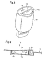
- Fig. 8 is a perspective view of the buckle 63
- Fig. 9 is a sectional view of a child seating detection device.
- the tongues 62 are attached to shoulder webbings 61 for a child.
- the tongues 62 are inserted into the buckle 63.
- the buckle 63 is mounted at the front part on the seat portion 12 of the child seat body 10 using the support member 64.
- an insertion opening 63b into which the tongues 62 are inserted is formed on a rear side of an upper end surface of the buckle 63.
- the tongues 62 are latched by latch mechanisms (not shown) in the buckle 63.
- latch sensors (not shown) are provided in order to detect latching of the tongues 62.
- a press button 63a is disposed on the front side of the upper end surface of the buckle 63. When the press button 63a is pressed, this latching is released and the tongues 62 are pushed upward so as to be detached from the insertion opening 63b by an operation of return springs of the latch mechanisms.
- An LED 65 serving as a light-emitting body is provided on a rear side of an upper inner surface of the insertion opening 63b so as to illuminate inside the insertion opening 63b.
- the LED 65 is turned on (may be continuously turned on or may blink) when a child is seated in the seat portion 12, and turned off when the tongues 62 are attached to the buckle 63 or a specified period of time has elapsed after a time when the child is seated.
- a seating detection device 70 is provided in the seat portion 12 of the child seat body 10. As illustrated in Fig.
- the seating detection device 70 includes a recess portion 12a, a plate 71, a stopper 72, a return spring 73, and a limit switch 74.
- the recess portion 12a is formed in a part of the seat portion 12 on which the bottom of the child is placed, and the plate 71 covers the recess portion 12a.
- the stopper 72, the return spring 73, and the limit switch 74 are provided on a lower surface of the plate 71.
- the plate 71 has an L-shaped leg portion 71a that protrudes downward from a rear edge of the plate 71.
- the leg portion 71a is inserted into and hooked to an opening 12b formed in a rear edge of a bottom surface of the recess portion 12a.
- the plate 71 is pivotable about the opening 12b as the pivot in the up-down direction.
- the plate 71 has a size such that the plate 71 can be fitted into the recess portion 12a.
- the return spring 73 includes a coil spring that is disposed between a bottom surface of the recess portion 12a and the plate 71, and urges the plate 71 toward a direction in which the plate 71 is pushed up.
- the stopper 72 includes a protrusion having a height with which the stopper 72 contacts the bottom surface of the recess portion 12a when the plate 71 is flush with part of the seat portion 12 that surrounds the recess portion 12a.
- the limit switch 74 is provided such that, when the plate 71 is flush with the seat portion 12, the limit switch 74 is brought into contact with the bottom surface of the recess portion 12a and turned on, and when the plate 71 is pushed upward by the return spring 73, the limit switch 74 is turned off.
- the plate 71 When the child is seated in the seat portion 12, the plate 71 is pushed down so as to turn the limit switch 74 on. In this state, when the child leaves the seat portion 12, the plate 71 is pushed up so as to turn the limit switch 74 off.
- a control device and a dry battery are mounted in the child seat body 10.
- the control device turns the LED 65 on and off in accordance with input signals received from the limit switch 74 of the seating detection device 70 and the latch sensors of the buckle 63.
- the dry battery supplies the power to the control device.
- the LED 65 blinks for a specified period of time (for example, 60 seconds to 5 minutes).
- the latch sensors detect the insertion and the LED 65 is turned off. As described above, when the child is seated in the child seat 10, the LED 65 at the insertion opening of the buckle 63 blinks.
- the insertion opening 63b into which the tongues 62 are to be inserted, can be easily recognized, and the user is motivated to insert the tongues 62 into the insertion opening 63b.
- the LED 65 is turned off when the tongues 62 are latched to the buckle 63, insertion of the tongues 62 into the buckle 63 can be recognized.
- a lamp that indicates that the seat belt has been correctly routed may be turned on (or may blink) for a specified period of time.
- the OK lamp includes, for example, a green LED.
- a lamp that indicates that the routing of the seat belt is not complete may be turned on (or may blink) when the start switch 44 is pressed, and the incomplete lamp may be turned off when the seat belt has been correctly routed.
- the OK lamp may be turned on for a specified period of time upon turning off of the incomplete lamp.
- the incomplete lamp may use, for example, a yellow LED.
- a child seat 80 according to another embodiment will be described below with reference to Figs. 10 and 11 .
- the child seat 80 is secured to the automobile seat with the seat belt 50 by applying tensile force. Tensile force is applied to the seat belt 50 by retracting the seat belt 50 using a retractor shaft 94.
- Fig. 10 is a perspective view of the child seat seen from the rear side.
- Fig. 11 is a perspective view illustrating a state in which the shoulder belt 51 of the three-point seat belt 50 is inserted into a slit for a shoulder belt of the retractor shaft of the child seat.
- the child seat 80 includes a seat portion 82, a backrest portion 84, ribs 86 and 88, seat belt routing openings 90 and 92, and the retractor shaft 94.
- a child occupant sits in the seat portion 82.
- the ribs 86 and 88 are formed on the backrest portion 84 so as to rearwardly protrude from left and right side edges of a rear surface of the backrest portion 84.
- the seat belt routing openings 90 and 92 are formed in the ribs 86 and 88, respectively.
- the retractor shaft 94 retracts the seat belt.
- the retractor shaft 94 extends in the up-down direction along the backrest portion 84 near the central part of the backrest portion 84.
- the retractor shaft 94 has a slit 94a with which the seat belt 50 is engaged.
- the slit 94a diametrically penetrates the retractor shaft 94 and extends in the axial direction (up-down direction) of the retractor shaft 94.
- the slit 94a has a cutout-shaped belt access opening 94b formed at a lower end thereof.
- Each of the ribs 86 and 88 extends along the rear surface of the backrest portion 84 in the up-down direction.
- Each of the seat belt routing openings 90 and 92 also extends along the backrest portion 84 in the up-down direction.
- An upper end side of the retractor shaft 94 is supported by a bracket 96 that is attached to the rear surface of the backrest portion 84 such that the retractor shaft 94 is rotatable about the axis of the retractor shaft 94 relative to the bracket 96.
- a lower end of the retractor shaft 94 is inserted into a mechanical box 98 that is provided in a lower part of the backrest portion 84.
- the retractor shaft 94 is rotated by rotation of a hand-wheel 102 using a worm wheel mechanism provided in the mechanical box 98 and a shaft 100.
- Lighting devices 104 are provided so as to illuminate an area near the slit 94a.
- the lighting devices 104 include LEDs and disposed in portions on the left and right sides of the slit 94a in the rear surface of the backrest portion 84. When the lighting devices 104 are disposed in these portions, the area near the slit 94a can be sufficiently illuminated from both the left and right sides.
- illuminating light does not directly strike the eyes of the operator. Thus, the operator is not dazzled by the light.
- Switches 106 which turn on the lighting devices 104, are provided on outwardly facing side surfaces of the ribs 86 and 88.
- the lighting devices 104 are turned on for a specified period of time (for example, 5 to 10 minutes), and then automatically turned off.
- the switch 106 is pressed again while the lighting devices 104 are turned on, the lighting device 104 are turned off.
- a circuit that controls turning on and off of the lighting devices 104 and a battery is disposed in an appropriate space such as a space in the mechanical box 98 or spaces in the ribs 86 and 88.
- the child seat 80 is placed on the seat of the automobile, and the switch 106 is pressed to turn the lighting devices 104 on. Then, the lap belt 52 and the shoulder belt 51 of the seat belt 50 are routed from one of the seat belt routing openings 90 and 92 to the other of the seat belt routing openings 90 and 92, then the tongue (not shown) are latched to the buckle (not shown). After that, as illustrated in Fig. 11 , an intermediate portion of the shoulder belt 51 is inserted into the slit 94a through the belt access opening 94b of the retractor shaft 94.
- the hand-wheel 102 is rotated to rotate the retractor shaft 94, in order to retract the shoulder belt 51 on the retractor shaft 94 until sufficient tensile force is applied to the entire seat belt 50.
- the child seat 80 is firmly secured to the seat of the automobile.
- the lighting devices 104 Since this series of operations typically take about 5 minutes to complete, the lighting devices 104 remain turned on during the mounting of the child seat. Thus, operations performed behind the backrest portion 84 such as engagement of the shoulder belt 51 with the slit 94a can be efficiently performed. After that, the lighting devices 104 are automatically turned off. Thus, battery power is not wasted.
- Mounting positions and the numbers of the lighting devices 104 and the switches 106 are not limited to those illustrated in Figs. 10 and 11 .
- a fluorescent coating may be applied to the retractor shaft 94, particularly near the slit 94a, so as to clearly indicate a portion through which the seat belt is to be routed.
- the rear surface of the backrest portion 84 may be light toned so as to improve effects of illumination with the lighting devices 104.
Landscapes
- Engineering & Computer Science (AREA)
- Mechanical Engineering (AREA)
- Health & Medical Sciences (AREA)
- Child & Adolescent Psychology (AREA)
- General Health & Medical Sciences (AREA)
- Aviation & Aerospace Engineering (AREA)
- Transportation (AREA)
- Seats For Vehicles (AREA)
- Chair Legs, Seat Parts, And Backrests (AREA)
Abstract

Description
- The present invention relates to a child seat that is installed on a seat of an automobile, and in particular, relates to a child seat that is secured using a seat belt of a seat belt device of the automobile.
- A variety of structures that secure a child seat installed on a seat of an automobile to the seat are proposed. One such example is described in Japanese Unexamined Patent Application Publications No.
2004-130996 2003-252094 - Japanese Unexamined Patent Application Publication No.
2004-130996 - Japanese Unexamined Patent Application Publication No.
2003-252094 -
- PTL 1: Japanese Unexamined Patent Application Publication No.
2004-130996 - PTL 2: Japanese Unexamined Patent Application Publication No.
2003-252094 - When the child seat is placed on the seat of an automobile, a space behind the child seat may be dark because the child seat may block the interior light of the automobile. This may make it difficult to route the seat belt around the child seat.
- An object of the present invention is to provide a child seat that allows a seat belt to be easily routed along the child seat when the child seat is placed on a seat and secured using the seat belt.
- A child seat of a first embodiment is mounted on a seat of an automobile by routing a seat belt of the automobile through a seat belt routing region. The child seat includes a lighting device that illuminates at least part of the seat belt routing region.
- In the child seat of a second embodiment, the child seat according to the first embodiment further includes a child seat body that has a seat portion and a backrest portion, and a base that supports the child seat body. In the child seat of the second embodiment, the lighting device is disposed so as to illuminate at least a rear side of the backrest portion.
- In the child seat of a third embodiment, the child seat according the second embodiment further includes a retractor member that is disposed at the rear side of the backrest portion and that retracts the seat belt in order to apply tensile force to the seat belt. In the child seat of the third embodiment, the lighting device is disposed so as to illuminate at least an engagement portion of the retractor member that is engaged with the seat belt.
- In the child seat of a fourth embodiment, the child seat according to any one of the first to third embodiments further includes a switch that causes the lighting device to start lighting, and light controlling means that causes the lighting device to be turned off when the routing of the seat belt is complete, or after a specified period of time has elapsed from a time when the switch is operated.
- In the child seat of a fifth embodiment, the child seat according to any one of the first to fourth embodiments has a plurality of belt routing portions through which the seat belt of the automobile is routed in order to mount the child seat on the seat of the automobile. In the child seat of the fifth embodiment, a light-emitting body is provided, the light-emitting body is turned on, in mounting the child seat on the seat of the automobile, so as to indicate the belt routing portion through which the seat belt is to be routed.
- In the child seat of a sixth embodiment, the child seat according to the fourth embodiment has a plurality of belt routing portions through which the seat belt of the automobile is routed in order to mount the child seat on the seat of the automobile. In the child seat of the sixth embodiment, light-emitting body is provided. The light-emitting body is turned on, in mounting the child seat on the seat of the automobile, so as to indicate the belt routing portion through which the seat belt is to be routed. In this case, the child seat includes light-emitting body controlling means that causes the light-emitting body to be turned on when the switch is operated.
- In the child seat of a seventh embodiment, the child seat according to the sixth embodiment further includes belt detection devices provided for respective belt routing portions. In the child seat of the seventh embodiment, the light-emitting body controlling means controls the light-emitting bodies such that the light-emitting body controlling means first causes the light-emitting body corresponding to the first belt routing portion, through which the seat belt is first to be routed, to be turned on. In this case, the light-emitting body controlling means causes, when the belt detection device for the first belt routing portion detects that the seat belt has been routed through the first belt routing portion, the light-emitting body corresponding to the first belt routing portion to be turned off. The light-emitting body controlling means then causes the light-emitting body corresponding to the second belt routing portion to be turned on. The second belt routing portion is a belt routing portion through which the seat belt is next to be routed. The light-emitting body controlling means causes the light-emitting body corresponding to the second belt routing portion to be turned off when the belt detection device for the second belt routing portion detects that the seat belt has been routed through the second belt routing portion.
- In the child seat of an eighth embodiment, the child seat according to the seventh embodiment further includes installation direction detecting means that detects whether the child seat is installed so as to face a forward direction or a rear direction of the automobile. As the belt routing portions, the child seat of the eighth embodiment includes a belt routing portion for a forward-facing installation through which the seat belt is routed when the child seat is installed so as to face a forward direction, and a belt routing portion for a rear-facing installation through which the seat belt is routed when the child seat is installed so as to face a rear direction. In the child seat of the eight embodiment, the light-emitting body controlling means causes, in accordance with an installation direction detected by the installation direction detecting means, either of the light-emitting body for the belt routing portion for the forward-facing installation and the light-emitting body for the belt routing portion for the rear-facing installation to be turned on.
- A child seat of a ninth embodiment includes a seat portion in which a child is seated, a webbing for a child that restrains the child seated in the seat portion, a tongue that is provided in the webbing for a child, and a buckle into which the tongue is inserted so as to be latched. The child seat of the ninth embodiment also includes a light-emitting body that is provided in the buckle, and means for controlling buckle light-emitting body that causes the light-emitting body to be turned on from a time when the child is seated in the seat portion to a time when a specified period of time has elapsed, or to a time when the tongue is latched.
- In the child seat of the first embodiment, when the child seat is mounted on the seat of the automobile using the seat belt, at least part of the seat belt routing region can be illuminated with a lighting device. This facilitates the routing of the seat belt.
- In the child seat of the second embodiment, the rear side of the backrest portion is illuminated. This facilitates the routing of the seat belt on the rear side of the backrest portion.
- In the child seat of the third embodiment, the engagement portion of the retractor member that is engaged with the seat belt on the rear side of the backrest portion is illuminated using the lighting device. This facilitates an operation in which the seat belt is engaged with the engagement portion of the retractor member.
- In the child seat of the fourth embodiment, the lighting device is turned off when the routing of the seat belt is complete, or after a specified period of time has elapsed from a time when the lighting device is turned on. This prevents a power source of the lighting device from being wasted. When the child seat is configured such that the lighting device is turned off when the routing of the seat belt is complete, the fact that the routing of the seat belt is complete is recognizable due to turning off of the lighting device.
- In the child seat of the fifth and sixth embodiments, the belt routing portions through which the seat belt is to be routed are indicated by turning on of the light-emitting bodies. Thus, when routing the seat belt through the belt routing portions after the child seat has been installed on the seat of the automobile, the belt routing portions through which the seat belt is to be routed are very easily recognizable. In particular, in the child seat of the fifth embodiment, when the switch is operated in order to turn on the lighting device, the light-emitting bodies are also turned on. Thus, the routing of the seat belt can be smoothly started.
- In the child seat of the seventh embodiment, when the switch is operated, the light-emitting body corresponding to the first belt routing portion is initially turned on. When the seat belt has been routed through the first belt routing portion, the light-emitting body corresponding to the first belt routing portion is turned off, and the light-emitting body corresponding to the second belt routing portion is turned on. Thus, when routing the seat belt through the belt routing portions, a series of operational procedure, in which the seat belt is initially routed through the first belt routing portion and then through the second belt routing portion, can be easily performed.
- In the child seat of the eighth embodiment, when the child seat is installed so as to face the forward direction of the automobile, the light-emitting body for the belt routing portion for the forward-facing installation is turned on. When the child seat is installed so as to face the rear direction, the light-emitting body for the belt routing portion for rear-facing installation is turned on. Thus, regardless of whether the child seat is directed forward or rearward, the belt routing portion through which the seat belt is to be routed is easily recognizable.
- In the child seat of the ninth embodiment, when the child is seated in the seat portion, the light-emitting body for a buckle is turned on. Thus, it is recognizable that the tongue for restraining a child is to be inserted into the buckle.
-
- [
Fig. 1] Fig. 1a is a perspective view of a child seat according to an embodiment, andFig. 1b is a vertical sectional view of a part where a lighting device is installed. - [
Fig. 2] Figs. 2a and 2b are perspective views of the child seat according to the embodiment. - [
Fig. 3] Fig. 3 is a perspective view illustrating a back portion of a child seat body according to the embodiment. - [
Fig. 4] Figs. 4a and 4b are sectional views illustrating a mounting structure of a limit switch. - [
Fig. 5] Fig. 5 is a perspective view of the child seat that is installed so as to face a forward direction. - [
Fig. 6] Fig. 6 is a perspective view of the child seat that is installed so as to face a rear direction. - [
Fig. 7] Fig. 7 is a front view of tongues for a child and a buckle. - [
Fig. 8] Fig. 8 is a perspective view of the buckle. - [
Fig. 9] Fig. 9 is a sectional view of a seating detection device. - [
Fig. 10] Fig. 10 is a perspective view of a child seat according to another embodiment. - [
Fig. 11] Fig. 11 is a perspective view of the child seat illustrated inFig. 10 with which the seat belt is engaged. - Embodiments will be described below with reference to the drawings.
-
Fig. 1a is a perspective view of a front side of a child seat according to an embodiment.Fig. 1b is a vertical sectional view of a part where a lighting device is installed.Figs. 2a and 2b are perspective views of a rear surface side of a child seat body.Fig. 3 is a perspective view of an upper part of a back portion of a base.Figs. 4a and 4b are sectional views illustrating the structure of a limit switch.Figs. 5 and6 are perspective views of the child seat with a seat belt routed around. - A
child seat 1 includes achild seat body 10 and abase 20. Thechild seat body 10 is mounted to the base 20 such that thechild seat body 10 is reclinable relative to thebase 20. Thechild seat body 10 has abackrest portion 11 and aseat portion 12. - Two pairs of
protrusion pieces 14 respectively protrude rearward from left and right sides of an upper part of a rear surface of thebackrest portion 11. Theprotrusion pieces 14 are engaged with guide portions (not shown) of the base 20 such that theprotrusion pieces 14 are slidable relative to the guide portions in an up-down direction. -
Belt hook portions 15 are provided on left and right side surfaces of an upper part of thechild seat body 10. The seat belt is hooked to thebelt hook portions 15 when thechild seat 1 is installed in a rear-facing installation state in which thechild seat 1 faces a rear direction of an automobile. In the present embodiment, thebelt hook portions 15 are each have an L-shaped hook-like shape in side view with an upper end open. In the present embodiment, thebelt hook portions 15 are formed separately from thechild seat body 10. A lower end part of eachbelt hook portion 15 is fastened to the corresponding side surface of thechild seat body 10 using fastening devices such as bolts. Thebelt hook portions 15 may be integrally formed with thechild seat body 10. -
Lighting devices 46 are provided on the rear surface of thebackrest portion 11 in order to illuminate a space between thebackrest portion 11 and thebase portion 20 when hooking the seat belt. In the present embodiment, thelighting devices 46 each include an LED and are each mounted in thebackrest portion 11 using alight holder 47 as illustrated inFig. 1b . Although thelighting devices 46 are disposed on the left and right sides of thebackrest portion 11 near a middle position in the up-down direction of thebackrest portion 11, the number and mounting positions of thelighting devices 46 are not limited to this. For example, a lighting device that illuminates an area under theseat portion 12 may be additionally provided. The lighting devices may use a light-emitting body other than the LED. - At a central part of a front portion of the
seat portion 12, abuckle 63 is provided using asupport member 64. Tongues of webbings for a child that restrain a child seated in theseat portion 12 are inserted into thebuckle 63. - The
base 20 has a substantially L-shape in side view and has abottom portion 21 and aback portion 22. Theback portion 22 is formed so as to rise from thebottom portion 21. Thebase 20 is provided with guide rails (not shown) that support thechild seat body 10 such that thechild seat body 10 is reclinable relative to thebase 20. - As illustrated in
Figs. 2a and 2b , arecess portion 23 is formed so as to extend from a bottom surface of thebottom portion 21 to a lower part of a back surface of theback portion 22. Abottom block 24 is engaged with therecess portion 23 such that thebottom block 24 is movable relative to therecess portion 23 in a front-rear direction. Therecess portion 23 hasguide grooves 25 that extend in the front-rear direction in left and right falling walls of therecess portion 23. Theguide grooves 25 are engaged with guide pins (not shown) that protrude from both side surfaces of thebottom block 24 so as to allow thebottom block 24 to slide in the front-rear direction. - The
bottom block 24 has a trapezoid-shaped vertical section in the front-rear direction. As illustrated inFig. 2a , when thebottom block 24 is positioned at the rearmost part (rearmost seen from a child seated in the child seat) of therecess portion 23, thebottom block 24 protrudes downward from a rear part of the bottom surface of thebottom portion 21 so as to make thechild seat 1 be suitable to a forward-facing installation. In order to detect that thebottom block 24 is positioned at the rearmost part, alimit switch 26 is provided in therecess portion 23. - When the
bottom block 24 is positioned at the frontmost part, thebottom block 24 protrudes downward from a front part of the bottom surface of thebottom portion 21 as illustrated inFig. 2b so as to make thechild seat 1 be suitable to the rear facing installation. In order to detect that thebottom block 24 is positioned at the frontmost part, alimit switch 27 is provided in therecess portion 23. In a state illustrated inFig. 2b , the thickness of thebottom block 24 increases toward the front, and the height from thebottom portion 21 increases toward the front. - As illustrated in
Fig. 3 ,belt routing portions 30 are provided on left and right sides of a front surface of the upper part of theback portion 22. Thebelt routing portions 30 each have ahook portion 31 having an inverted L-shape and alock portion 32 that is engaged with a lower end of thehook portion 31. Eachlock portion 32 is secured by a hinge (not shown) so as to be pivotable in directions indicated by the arrow θ. - When the
lock portion 32 is pivoted downward, ashoulder webbing 51 of the seat belt can be inserted into or removed out of thebelt routing portion 30. Eachbelt routing portion 30 is provided with alimit switch 33 in order to detect the seat belt routed therethrough.LED units 34 are provided at positions close to thebelt routing portions 30 in side surfaces of the upper part of theback portion 22. EachLED unit 34 includes a pair of red and blue LEDs and is configured such that theLED unit 34 can be turned on to emit red or blue light in accordance with commands from a control circuit, which will be described later. In detail, in the present embodiment, theLED units 34 emit red light when thechild seat 1 is installed so as to face a forward direction, and emit blue light when thechild seat 1 is installed so as to face the rear direction. - An upwardly facing step-like
belt routing portion 37 is provided on each of the left and right sides on the front surface of theback portion 22 at a middle position in the up-down direction. Eachbelt routing portion 37 is provided with alimit switch 38 that detects the seat belt. The limit switches 38 are disposed in left and right edge parts in the front surface of theback portion 22. ARed LED 39 is provided near thebelt routing portions 37 in each of the left and right side surfaces of theback portion 22. -
Figs. 4a and 4b illustrate an installation structure of thelimit switch 38. Eachlimit switch 38 includes amain body portion 38a and anactuator 38b. Themain body portion 38a is mounted on a back side of thebelt routing portion 37. The actuator 38b protrudes from themain body portion 38a to a front surface of thebelt routing portion 37 as illustrated inFig. 4a . As illustrated inFig. 4b , thelimit switch 38 is turned on when theactuator 38b is pushed by theseat belt 51 and retracted. Other limit switches have a similar structure, although they are not illustrated in the drawings. - As illustrated in
Fig. 1a , abelt routing portion 40 is formed in an upper surface of the front part of thebottom portion 21. Thebelt routing portion 40 includes a groove that extends from a left side to a right side of thebottom portion 21. Limit switches 41 that detect the seat belt are provided at left and right ends of thebelt routing portion 40. On each side surface of thechild seat body 10, ablue LED 42 is provided at a position close to thebelt routing portion 40. - A
start switch 44 is provided at the side surface of theback portion 22 of thebase 20. Thestart switch 44 causes thelighting devices 46 and the LEDs to start lighting (blinking in the present embodiment). The control circuit and a dry battery are mounted on thebase 20, although these are omitted in the drawings. The control circuit is connected to the LEDs, the limit switches, and thestart switch 44 through lead wires. The dry battery supplies power to the control circuit. The method of supplying the power (a power source) to the control circuit is not limited to the dry battery. A lithium battery may be used instead of the dry battery. Alternatively, instead of providing an internal power source such as the dry battery or the lithium battery in thechild seat 1, an external power source such as a vehicle battery may be used to supply the power to the control circuit through, for example, a cigarette lighter socket of a vehicle. - As illustrated in
Figs. 5 and6 , in aseat belt 50 of a seat belt device of the automobile, one side of atongue 53 is theshoulder belt 51 and the other side of thetongue 53 is alap belt 52. Thetongue 53 can be attached (latched) to abuckle 54. Theshoulder belt 51 is hooked between thebuckle 54 of a seat of a vehicle and a shoulder anchor (not shown) provided at an upper position diagonally opposite thebuckle 54. Theseat belt 50 is withdrawn from a seat belt retractor (not shown) equipped with an automatic lock mechanism. The automatic lock mechanism is a mechanism that, after a seat belt withdrawing operation has stopped, allows the seat belt only to be retracted while preventing the seat belt from being withdrawn until the tongue is pulled out of the buckle. - A procedure for securing the
child seat 1 to the seat of the automobile using theseat belt 50 will be described below. - When the
child seat 1 is installed so as to face the forward direction, thebottom block 24 is positioned at the rearmost part of therecess portion 23 as illustrated inFig. 2a . Thechild seat 1 is placed on the seat so as to face a forward direction of the automobile. Theback portion 22 is pressed against a seat back of the seat. Then, thestart switch 44 is pressed. As a result, thelighting devices 46 are turned on so as to illuminate a rear-side space between thechild seat body 10 and theback portion 22 of thebase 20, and thered LEDs 39 blink. Then the user inserts thetongue 53 into the space between thechild seat body 10 and theback portion 22, routes theseat belt 50 through this space, and inserts thetongues 53 into thebuckle 54 such that thetongue 53 is latched to thebuckle 54. In so doing, since thelighting devices 46 are turned on, an operation of routing theseat belt 50 in the rear side space can be easily performed. - After the
tongue 53 is latched to thebuckle 54, thelap belt 52 is routed along thebelt routing portions 37. As a result, thelap belt 52 contacts the limit switches 38, and the fact that thelap belt 52 has been routed along thebelt routing portions 37 is detected. This causes theLEDs 39 to be turned off. Instead, theLED units 34 at the upper position blink. As described above, when thechild seat 1 is installed so as to face the forward direction, theLED units 34 blink red, which is the same color as the color of light emitted by theLEDs 39. Then, the user hooks theshoulder belt 51 through thebelt routing portion 30 as illustrated inFigs. 3 and5 . As a result, theshoulder belt 51 comes into contact with thecorresponding limit switch 33, thereby turning off theLED units 34. As a result, all the LEDs and the LED units that guide the routing of the belts have been turned off. Thus, the fact that thechild seat 1 has been mounted on the seat by theseat belt 50 is recognizable. Thelighting devices 46 may be turned off along with turning off of theLED units 34. Thus, the fact that thechild seat 1 has been mounted on the seat using theseat belt 50 is recognizable due to turning off of thelighting devices 46. - Next, a procedure for installing the
child seat 1 so as to face the rear direction will be described with reference toFig. 6 . - In this case, the
bottom block 24 is positioned at the frontmost part of therecess portion 23 as illustrated inFig. 2b . Thechild seat 1 is placed on the seat so as to face the rear direction of the automobile, that is, thechild seat 1 is placed such that, when a child is seated in thechild seat 1, the child faces the rear direction of the automobile. - When the
start switch 44 is pressed, thelighting devices 46 are turned on, and theblue LEDs 42 blink. Then the user routes thetongue 53 and thelap belt 52 into a space between thechild seat body 10 and thebottom portion 21, and inserts thetongue 53 into thebuckle 54 such that thetongue 53 is latched to thebuckle 54. Thelap belt 52 is also routed along thebelt routing portion 40. As a result, thelap belt 52 contacts the limit switches 41. This causes theLEDs 42 to be turned off and theLED units 34 to blink. As described above, when thechild seat 1 is installed so as to face the rear direction, theLED units 34 blink blue, which is the same color as the color of light emitted by theLEDs 42. Then, as illustrated inFig. 6 , that is, out of the left and rightbelt hook portions 15 of thechild seat body 10, the user hooks theshoulder belt 51 in thebelt hook portion 15 positioned on the shoulder anchor side of the vehicle. The user diagonally routes theshoulder belt 51 behind thechild seat body 10, and hooks the intermediate portion of theshoulder belt 51 through thebelt routing portion 30 on the shoulder anchor side. Since thelighting devices 46 are turned on, the user can easily route theshoulder belt 51 in the space between thechild seat body 10 and theback portion 22 and hook theshoulder belt 51 in thebelt routing portion 30. When theshoulder belt 51 comes into contact with the limit switches 33, theLED units 34 are turned off. As a result, all the LEDs and the LED units that guide the routing of the belts have been turned off. Thus, the fact that thechild seat 1 has been secured to the seat by theseat belt 50 is recognizable. In the present embodiment, thelighting devices 46 are turned off along with turning off of theLED units 34. Thus, the fact that thechild seat 1 has been mounted on the seat using theseat belt 50 is also recognizable due to turning off of thelighting devices 46. - The
seat belt 50 may loosen after thechild seat 1 has been mounted on the seat using theseat belt 50 as illustrated inFigs. 5 and6 as a result of such a situation as thechild seat 1 being pressed against the seat. In the present embodiment, thechild seat 1 is configured such that, when the seat belt becomes undetectable by any one of the limit switches due to such looseness, the LED or LED unit (or every LED or LED unit) near this limit switch blinks. Thus, loosening of theseat belt 50 is announced to the user. - In the present embodiment, the
LEDs lighting devices 46 continue to be turned on from a time when thestart switch 44 is pressed to a time when one of the limit switches first detects the seat belt. However, since turning on of theLEDs lighting devices 46 for an excessively long time causes battery power to be quickly drained, thechild seat 1 is configured such that the lights are turned off when five minutes have elapsed from the time when thestart switch 44 is pressed. - In the present embodiment, the forward-facing installation and the rear-facing installation are switched by sliding the
bottom block 24 back and forth. Alternatively, the forward-facing and rear-facing installations may be switched by pivoting the bottom block back and forth as disclosed in the above-described Japanese Unexamined Patent Application Publication No.2003-252094 - In the present invention, the rear-facing installation state may be recognized due to detection of the fact that the
child seat body 10 has been deeply reclined using a limit switch or the like, and the forward-facing installation state may be recognized due to detection of the fact that thechild seat body 10 has been elected. - In the above-described embodiment, the LEDs blink. Alternatively, the LEDs may be continuously turned on.
- In the above-described embodiment, the LEDs on the left and right sides are simultaneously turned on. However, the LEDs on only one of the left and right sides may be turned on by switching between a case in which the
child seat 1 is installed on a seat on the left side of the automobile and another case in which thechild seat 1 is installed on a seat on the right side of the automobile using a switch. - In the above-described embodiment, the
child seat 1 is configured as follows. That is, when thestart switch 44 is pressed, thelighting devices 46 are initially turned on, and theLEDs 39 for thebelt routing portions 37 or theLEDs 42 for thebelt routing portion 40, through which the seat belt is first to be routed, are turned on. Then, when it is detected that the seat belt has been routed through thebelt routing portions LEDs 42 or theLEDs 39 are turned off, and theLED units 34 for thebelt routing portion 30 through which the seat belt is to be routed next is instead turned on. Thechild seat 1 may alternatively be configured such that, when thechild seat 1 is installed so as to face the forward or rear direction, the LEDs and LED units for all the corresponding belt routing portions through which the seat belt is to be routed are turned on, and every time the seat belt is routed through a particular belt routing portion, the LEDs or the LED units for the particular belt routing portion are turned off. - In the present invention, when a tongue of a webbing for a child is inserted into a buckle for a child, a tongue insertion opening of the buckle for a child may be indicated by a light-emitting body such as an LED.
-
Figs. 7 to 9 illustrate an example of this structure.Fig. 7 is a front view of thebuckle 63 andtongues 62,Fig. 8 is a perspective view of thebuckle 63, andFig. 9 is a sectional view of a child seating detection device. - As illustrated in
Fig. 7 , thetongues 62 are attached to shoulderwebbings 61 for a child. Thetongues 62 are inserted into thebuckle 63. As illustrated inFig. 1a , thebuckle 63 is mounted at the front part on theseat portion 12 of thechild seat body 10 using thesupport member 64. - As illustrated in
Fig. 8 , aninsertion opening 63b into which thetongues 62 are inserted is formed on a rear side of an upper end surface of thebuckle 63. When thetongues 62 are inserted into theinsertion opening 63b, thetongues 62 are latched by latch mechanisms (not shown) in thebuckle 63. Inside thebuckle 63, latch sensors (not shown) are provided in order to detect latching of thetongues 62. Apress button 63a is disposed on the front side of the upper end surface of thebuckle 63. When thepress button 63a is pressed, this latching is released and thetongues 62 are pushed upward so as to be detached from theinsertion opening 63b by an operation of return springs of the latch mechanisms. - An
LED 65 serving as a light-emitting body is provided on a rear side of an upper inner surface of theinsertion opening 63b so as to illuminate inside theinsertion opening 63b. TheLED 65 is turned on (may be continuously turned on or may blink) when a child is seated in theseat portion 12, and turned off when thetongues 62 are attached to thebuckle 63 or a specified period of time has elapsed after a time when the child is seated. In order to detect that the child is seated, aseating detection device 70 is provided in theseat portion 12 of thechild seat body 10. As illustrated inFig. 9 , theseating detection device 70 includes arecess portion 12a, aplate 71, astopper 72, areturn spring 73, and alimit switch 74. Therecess portion 12a is formed in a part of theseat portion 12 on which the bottom of the child is placed, and theplate 71 covers therecess portion 12a. Thestopper 72, thereturn spring 73, and thelimit switch 74 are provided on a lower surface of theplate 71. - The
plate 71 has an L-shapedleg portion 71a that protrudes downward from a rear edge of theplate 71. Theleg portion 71a is inserted into and hooked to anopening 12b formed in a rear edge of a bottom surface of therecess portion 12a. Theplate 71 is pivotable about theopening 12b as the pivot in the up-down direction. Theplate 71 has a size such that theplate 71 can be fitted into therecess portion 12a. Thereturn spring 73 includes a coil spring that is disposed between a bottom surface of therecess portion 12a and theplate 71, and urges theplate 71 toward a direction in which theplate 71 is pushed up. Thestopper 72 includes a protrusion having a height with which thestopper 72 contacts the bottom surface of therecess portion 12a when theplate 71 is flush with part of theseat portion 12 that surrounds therecess portion 12a. - The
limit switch 74 is provided such that, when theplate 71 is flush with theseat portion 12, thelimit switch 74 is brought into contact with the bottom surface of therecess portion 12a and turned on, and when theplate 71 is pushed upward by thereturn spring 73, thelimit switch 74 is turned off. - When the child is seated in the
seat portion 12, theplate 71 is pushed down so as to turn thelimit switch 74 on. In this state, when the child leaves theseat portion 12, theplate 71 is pushed up so as to turn thelimit switch 74 off. - A control device and a dry battery are mounted in the
child seat body 10. The control device turns theLED 65 on and off in accordance with input signals received from thelimit switch 74 of theseating detection device 70 and the latch sensors of thebuckle 63. The dry battery supplies the power to the control device. When theseating detection device 70 detects that the child is seated, theLED 65 blinks for a specified period of time (for example, 60 seconds to 5 minutes). When thetongues 62 are inserted into thebuckle 63, the latch sensors detect the insertion and theLED 65 is turned off. As described above, when the child is seated in thechild seat 10, theLED 65 at the insertion opening of thebuckle 63 blinks. Thus, theinsertion opening 63b, into which thetongues 62 are to be inserted, can be easily recognized, and the user is motivated to insert thetongues 62 into theinsertion opening 63b. In addition, since theLED 65 is turned off when thetongues 62 are latched to thebuckle 63, insertion of thetongues 62 into thebuckle 63 can be recognized. - According to the present invention, when the seat belt has been correctly routed and every specified limit switch detects the seat belt in the forward-facing installation state or the rear-facing installation state, a lamp that indicates that the seat belt has been correctly routed (OK lamp) may be turned on (or may blink) for a specified period of time. The OK lamp includes, for example, a green LED.
- Furthermore, a lamp that indicates that the routing of the seat belt is not complete (incomplete lamp) may be turned on (or may blink) when the
start switch 44 is pressed, and the incomplete lamp may be turned off when the seat belt has been correctly routed. The OK lamp may be turned on for a specified period of time upon turning off of the incomplete lamp. The incomplete lamp may use, for example, a yellow LED. - A
child seat 80 according to another embodiment will be described below with reference toFigs. 10 and11 . Thechild seat 80 is secured to the automobile seat with theseat belt 50 by applying tensile force. Tensile force is applied to theseat belt 50 by retracting theseat belt 50 using aretractor shaft 94.Fig. 10 is a perspective view of the child seat seen from the rear side.Fig. 11 is a perspective view illustrating a state in which theshoulder belt 51 of the three-point seat belt 50 is inserted into a slit for a shoulder belt of the retractor shaft of the child seat. - The
child seat 80 includes aseat portion 82, abackrest portion 84,ribs belt routing openings retractor shaft 94. A child occupant sits in theseat portion 82. Theribs backrest portion 84 so as to rearwardly protrude from left and right side edges of a rear surface of thebackrest portion 84. The seatbelt routing openings ribs retractor shaft 94 retracts the seat belt. - The
retractor shaft 94 extends in the up-down direction along thebackrest portion 84 near the central part of thebackrest portion 84. Theretractor shaft 94 has aslit 94a with which theseat belt 50 is engaged. - The
slit 94a diametrically penetrates theretractor shaft 94 and extends in the axial direction (up-down direction) of theretractor shaft 94. Theslit 94a has a cutout-shaped belt access opening 94b formed at a lower end thereof. - Each of the
ribs backrest portion 84 in the up-down direction. Each of the seatbelt routing openings backrest portion 84 in the up-down direction. - An upper end side of the
retractor shaft 94 is supported by abracket 96 that is attached to the rear surface of thebackrest portion 84 such that theretractor shaft 94 is rotatable about the axis of theretractor shaft 94 relative to thebracket 96. A lower end of theretractor shaft 94 is inserted into amechanical box 98 that is provided in a lower part of thebackrest portion 84. Theretractor shaft 94 is rotated by rotation of a hand-wheel 102 using a worm wheel mechanism provided in themechanical box 98 and ashaft 100. -
Lighting devices 104 are provided so as to illuminate an area near theslit 94a. In the present embodiment, thelighting devices 104 include LEDs and disposed in portions on the left and right sides of theslit 94a in the rear surface of thebackrest portion 84. When thelighting devices 104 are disposed in these portions, the area near theslit 94a can be sufficiently illuminated from both the left and right sides. In addition, when an operator tries to route theseat belt 50 behind thebackrest portion 84, illuminating light does not directly strike the eyes of the operator. Thus, the operator is not dazzled by the light. -
Switches 106, which turn on thelighting devices 104, are provided on outwardly facing side surfaces of theribs switch 106 is pressed, thelighting devices 104 are turned on for a specified period of time (for example, 5 to 10 minutes), and then automatically turned off. When theswitch 106 is pressed again while thelighting devices 104 are turned on, thelighting device 104 are turned off. A circuit that controls turning on and off of thelighting devices 104 and a battery is disposed in an appropriate space such as a space in themechanical box 98 or spaces in theribs - A procedure for installing the
child seat 80 on the seat will be described below. - The
child seat 80 is placed on the seat of the automobile, and theswitch 106 is pressed to turn thelighting devices 104 on. Then, thelap belt 52 and theshoulder belt 51 of theseat belt 50 are routed from one of the seatbelt routing openings belt routing openings Fig. 11 , an intermediate portion of theshoulder belt 51 is inserted into theslit 94a through the belt access opening 94b of theretractor shaft 94. - Then, the hand-
wheel 102 is rotated to rotate theretractor shaft 94, in order to retract theshoulder belt 51 on theretractor shaft 94 until sufficient tensile force is applied to theentire seat belt 50. Thus, thechild seat 80 is firmly secured to the seat of the automobile. - Since this series of operations typically take about 5 minutes to complete, the
lighting devices 104 remain turned on during the mounting of the child seat. Thus, operations performed behind thebackrest portion 84 such as engagement of theshoulder belt 51 with theslit 94a can be efficiently performed. After that, thelighting devices 104 are automatically turned off. Thus, battery power is not wasted. - Mounting positions and the numbers of the
lighting devices 104 and theswitches 106 are not limited to those illustrated inFigs. 10 and11 . - In the present invention, a fluorescent coating may be applied to the
retractor shaft 94, particularly near theslit 94a, so as to clearly indicate a portion through which the seat belt is to be routed. The rear surface of thebackrest portion 84 may be light toned so as to improve effects of illumination with thelighting devices 104. - It should be understood that the above-described embodiments are examples of the present invention and the present invention may be embodied other than illustrated in the drawings.
- Although the present invention has been described in detail using specific embodiments, it will be appreciated by those skilled in the art that a variety of changes are possible without departing from the gist and the scope of the present invention.
The present application is based on a Japanese Patent Application (Japanese Patent Application No.2009-123345
Claims (10)
- A child seat that is mounted on a seat of an automobile by routing a seat belt of the automobile in a seat belt routing region, the child seat comprising
a lighting device that illuminates at least part of the seat belt routing region. - The child seat according to Claim 1, further comprising a child seat body that has a seat portion and a backrest portion, and a base that supports the child seat body,
wherein the lighting device is disposed so as to illuminate at least a rear side of the backrest portion. - The child seat according to Claim 2, further comprising a retractor member that is disposed at the rear side of the backrest portion and that retracts the seat belt in order to apply tensile force to the seat belt,
wherein the lighting device is disposed so as to illuminate at least an engagement portion of the retractor member that is engaged with the seat belt. - The child seat according to any one of Claims 1 to 3, further comprising a switch that causes the lighting device to start lighting, and light controlling means that causes the lighting device to be turned off when routing of the seat belt is complete, or after a specified period of time has elapsed from a time when the switch is operated.
- The child seat according to any one of Claims 1 to 4, wherein the child seat has a plurality of belt routing portions, the belt routing portions through which the seat belt of the automobile is routed in order to mount the child seat on the seat of the automobile,
wherein a light-emitting body is provided, the light-emitting body being turned on, in mounting the child seat on the seat of the automobile, so as to indicate the belt routing portion through which the seat belt is to be routed. - The child seat according to Claim 4, wherein the child seat has a plurality of belt routing portions, the belt routing portions through which the seat belt of the automobile is routed in order to mount the child seat on the seat of the automobile,
wherein a light-emitting body is provided, the light-emitting body being turned on, in mounting the child seat on the seat of the automobile, so as to indicate the belt routing portion through which the seat belt is to be routed, wherein the child seat includes light-emitting body controlling means that causes the light-emitting body to be turned on when the switch is operated. - The child seat according to Claim 6, further comprising belt detection devices provided for respective belt routing portions,
wherein the light-emitting body controlling means controls the light-emitting bodies such that the light-emitting body controlling means first causes the light-emitting body corresponding to the first belt routing portion to be turned on, the first belt routing portion being a belt routing portion through which the seat belt is first to be routed, the light-emitting body controlling means causing, when the belt detection device for the first belt routing portion detects that the seat belt has been routed through the first belt routing portion, the light-emitting body corresponding to the first belt routing portion to be turned off, the light-emitting body controlling means then causing the light-emitting body corresponding to the second belt routing portion to be turned on, the second belt routing portion being a belt routing portion through which the seat belt is next to be routed, the light-emitting body controlling means causing the light-emitting body corresponding to the second belt routing portion to be turned off when the belt detection device for the second belt routing portion detects that the seat belt has been routed through the second belt routing portion. - The child seat according to Claim 7,
further comprising installation direction detecting means that detects whether the child seat is installed so as to face a forward direction or a rear direction of the automobile,
wherein, as the belt routing portions, the child seat includes a belt routing portion for a forward-facing installation through which the seat belt is routed when the child seat is installed so as to face a forward direction, and a belt routing portion for a rear-facing installation through which the seat belt is routed when the child seat is installed so as to face a rear direction,
wherein the light-emitting body controlling means causes, in accordance with an installation direction detected by the installation direction detecting means, either of the light-emitting body for the belt routing portion for the forward-facing installation and the light-emitting body for the belt routing portion for the rear-facing installation to be turned on. - The child seat according to any one of Claims 1 to 8, wherein the lighting device includes an LED.
- A child seat that includes a seat portion in which a child is seated, a webbing for a child that restrains the child seated in the seat portion, a tongue that is provided in the webbing for a child, and a buckle into which the tongue is inserted so as to be latched, the child seat comprising
a light-emitting body that is provided in the buckle, and
means for controlling buckle light-emitting body that causes the light-emitting body to be turned on from a time when the child is seated in the seat portion to a time when a specified period of time has elapsed, or to a time when the tongue is latched.
Applications Claiming Priority (2)
| Application Number | Priority Date | Filing Date | Title |
|---|---|---|---|
| JP2009123345A JP5381322B2 (en) | 2009-05-21 | 2009-05-21 | child seat |
| PCT/JP2010/054198 WO2010134375A1 (en) | 2009-05-21 | 2010-03-12 | Child seat |
Publications (3)
| Publication Number | Publication Date |
|---|---|
| EP2433832A1 true EP2433832A1 (en) | 2012-03-28 |
| EP2433832A4 EP2433832A4 (en) | 2017-10-25 |
| EP2433832B1 EP2433832B1 (en) | 2018-10-24 |
Family
ID=43126064
Family Applications (1)
| Application Number | Title | Priority Date | Filing Date |
|---|---|---|---|
| EP10777611.4A Not-in-force EP2433832B1 (en) | 2009-05-21 | 2010-03-12 | Child seat |
Country Status (5)
| Country | Link |
|---|---|
| EP (1) | EP2433832B1 (en) |
| JP (1) | JP5381322B2 (en) |
| KR (1) | KR20120018112A (en) |
| CN (1) | CN102427965A (en) |
| WO (1) | WO2010134375A1 (en) |
Cited By (1)
| Publication number | Priority date | Publication date | Assignee | Title |
|---|---|---|---|---|
| US11147943B1 (en) | 2020-06-11 | 2021-10-19 | Demetrius Lumpkin | Vehicle nightlight assembly |
Families Citing this family (20)
| Publication number | Priority date | Publication date | Assignee | Title |
|---|---|---|---|---|
| JP5849424B2 (en) * | 2011-03-31 | 2016-01-27 | 因幡電機産業株式会社 | Cable support |
| US8911015B2 (en) * | 2013-03-05 | 2014-12-16 | Yochanan Cohen | Car seat |
| JP6080749B2 (en) * | 2013-12-04 | 2017-02-15 | ブリヂストンサイクル株式会社 | Lumbar belt fixing structure, child-carrying device and motorcycle |
| EP3031341B1 (en) * | 2014-12-12 | 2018-06-13 | AGM Automotive LLC | Illuminated safety restraint system |
| US20170349132A1 (en) * | 2014-12-22 | 2017-12-07 | Emma Garatea | Inflatable protection for a child seat |
| RU2716719C2 (en) * | 2015-06-02 | 2020-03-16 | ФОРД ГЛОУБАЛ ТЕКНОЛОДЖИЗ, ЭлЭлСи | Vehicle backhaul belt assembly (embodiments) |
| FR3069498B1 (en) * | 2017-07-28 | 2019-08-23 | Dorel France | CHILDREN'S AUTO SEAT WITH AUTOMATIC LIGHTING MEANS |
| CN110103786A (en) * | 2018-07-17 | 2019-08-09 | 宁波宝贝第一母婴用品有限公司 | A kind of child safety seat and its installation suggestion method with installation suggestion function |
| CN110857042B (en) * | 2018-08-25 | 2021-06-25 | 宁波宝贝第一母婴用品有限公司 | An indication system for securing a child safety seat using a vehicle seat belt |
| US11155188B2 (en) | 2019-01-10 | 2021-10-26 | Wonderland Switzerland Ag | Child restraint system and adjustable headrest assembly thereof |
| US11440446B2 (en) * | 2019-01-10 | 2022-09-13 | Wonderland Switzerland Ag | Child restraint system |
| US11447047B2 (en) | 2019-01-10 | 2022-09-20 | Wonderland Switzerland Ag | Child safety seat |
| CN110091775A (en) * | 2019-05-21 | 2019-08-06 | 麦克英孚(宁波)婴童用品有限公司 | A kind of safety belt of automotive child safety seat mounting system and method |
| CN113352964A (en) | 2020-03-03 | 2021-09-07 | 宝钜瑞士股份有限公司 | Forward misuse alarm device |
| CN113386639A (en) | 2020-03-13 | 2021-09-14 | 宝钜瑞士股份有限公司 | Child safety seat |
| CN113815502B (en) | 2020-06-19 | 2024-07-26 | 宝钜瑞士股份有限公司 | Child safety seat and side-impact protection mechanism thereof |
| CN113859065B (en) | 2020-06-30 | 2024-07-09 | 宝钜瑞士股份有限公司 | Child safety seat and side impact protection mechanism |
| AU2021201211B1 (en) | 2021-02-24 | 2021-08-12 | BRITAX RÖMER Kindersicherheit GmbH | Child restraint |
| CN117962710A (en) * | 2022-09-08 | 2024-05-03 | 居佳国际有限公司 | Carrier and belt guide mechanism |
| CN120303149A (en) * | 2022-11-21 | 2025-07-11 | 明门瑞士股份有限公司 | Child safety seats |
Family Cites Families (12)
| Publication number | Priority date | Publication date | Assignee | Title |
|---|---|---|---|---|
| DE2021716A1 (en) * | 1970-05-04 | 1972-01-13 | Schulz Globus Werke F | Furniture, in particular seating and / or reclining furniture |
| EP0228158A3 (en) * | 1985-10-30 | 1989-03-22 | Ase (Uk) Limited | Child's safety seat |
| JPS63172347U (en) * | 1987-04-28 | 1988-11-09 | ||
| US5260684A (en) * | 1991-05-14 | 1993-11-09 | Northpoint Manufacturing & Marketing, Inc. | Warning system for a child's restraining seat for use in a passenger vehicle |
| JP2000177451A (en) * | 1998-12-17 | 2000-06-27 | Tokai Rika Co Ltd | Child seat |
| CA2271527A1 (en) * | 1999-05-12 | 2000-11-12 | Karen Sorenson | Infant observation mirror attachable to an infant car seat |
| US6126233A (en) * | 1999-05-21 | 2000-10-03 | Gaetano; Steven | Child safety seat with integrated illumination |
| JP4131106B2 (en) | 2001-12-27 | 2008-08-13 | タカタ株式会社 | child seat |
| JP4107042B2 (en) * | 2002-10-11 | 2008-06-25 | タカタ株式会社 | child seat |
| US7819472B2 (en) * | 2006-12-12 | 2010-10-26 | Wonderland Nurserygoods Co., Ltd. | Latch mechanism for a child car seat |
| JP5157260B2 (en) * | 2007-05-30 | 2013-03-06 | タカタ株式会社 | Seat belt clamp device for child seat and child seat |
| JP2009123345A (en) | 2007-11-09 | 2009-06-04 | Gunze Ltd | Electrode for solid polymer fuel cell, manufacturing method of calcined film for solid polymer fuel cell, and solid polymer fuel cell |
-
2009
- 2009-05-21 JP JP2009123345A patent/JP5381322B2/en active Active
-
2010
- 2010-03-12 WO PCT/JP2010/054198 patent/WO2010134375A1/en not_active Ceased
- 2010-03-12 KR KR1020117021212A patent/KR20120018112A/en not_active Ceased
- 2010-03-12 EP EP10777611.4A patent/EP2433832B1/en not_active Not-in-force
- 2010-03-12 CN CN2010800211996A patent/CN102427965A/en active Pending
Non-Patent Citations (1)
| Title |
|---|
| See references of WO2010134375A1 * |
Cited By (1)
| Publication number | Priority date | Publication date | Assignee | Title |
|---|---|---|---|---|
| US11147943B1 (en) | 2020-06-11 | 2021-10-19 | Demetrius Lumpkin | Vehicle nightlight assembly |
Also Published As
| Publication number | Publication date |
|---|---|
| EP2433832A4 (en) | 2017-10-25 |
| CN102427965A (en) | 2012-04-25 |
| KR20120018112A (en) | 2012-02-29 |
| WO2010134375A1 (en) | 2010-11-25 |
| JP5381322B2 (en) | 2014-01-08 |
| JP2010269702A (en) | 2010-12-02 |
| EP2433832B1 (en) | 2018-10-24 |
Similar Documents
| Publication | Publication Date | Title |
|---|---|---|
| EP2433832B1 (en) | Child seat | |
| EP2269861B1 (en) | Child seat | |
| EP2374510B1 (en) | Automatic locking SCBA mounting bracket assembly | |
| US10696192B2 (en) | Child safety seat | |
| EP1053914B1 (en) | Switch for an automatic child seat detection and manual air bag deactivation device | |
| EP4063189A1 (en) | Tether assembly, and child safety seat and support structure thereof | |
| US9073506B2 (en) | Vehicle having a seat belt system | |
| JP2004330940A (en) | Seat slide device | |
| JP4073802B2 (en) | Seat slide device | |
| US9539938B1 (en) | Removable vehicle roof panel with stowing assistance lamps | |
| CN108725274A (en) | child seat restraint system | |
| JP6735410B2 (en) | Vehicle luggage compartment structure | |
| EP2834101B1 (en) | High back booster seat/child restraint | |
| US20240294122A1 (en) | Seat assembly, vehicle and assembly method with an accessory for the connection of a further component in the vehicle interior | |
| JP4415871B2 (en) | Console box structure | |
| JP2005119442A (en) | Seat with arm rests | |
| JP2001171428A (en) | Vehicle lighting system | |
| JP2004255994A (en) | Vehicle seat belt device | |
| JP2019151332A (en) | Vehicle seat and vehicle unit | |
| KR100526979B1 (en) | Device for displaying a locking for detachable seat of vehicles | |
| KR20250022436A (en) | Seat belt device and method for mounting the seat belt device | |
| KR0123745Y1 (en) | Seat cushion installation structure of automobile | |
| JP2011246039A (en) | Lighting system for vehicle cabin | |
| JP4703352B2 (en) | Seat device with foot lamp | |
| JP2005297799A (en) | Seat belt device |
Legal Events
| Date | Code | Title | Description |
|---|---|---|---|
| PUAI | Public reference made under article 153(3) epc to a published international application that has entered the european phase |
Free format text: ORIGINAL CODE: 0009012 |
|
| 17P | Request for examination filed |
Effective date: 20111109 |
|
| AK | Designated contracting states |
Kind code of ref document: A1 Designated state(s): AT BE BG CH CY CZ DE DK EE ES FI FR GB GR HR HU IE IS IT LI LT LU LV MC MK MT NL NO PL PT RO SE SI SK SM TR |
|
| DAX | Request for extension of the european patent (deleted) | ||
| RIC1 | Information provided on ipc code assigned before grant |
Ipc: B60N 2/44 20060101ALI20170616BHEP Ipc: A47C 7/72 20060101ALI20170616BHEP Ipc: B60N 2/28 20060101AFI20170616BHEP Ipc: B60Q 3/233 20170101ALI20170616BHEP Ipc: B60R 22/10 20060101ALI20170616BHEP Ipc: B60Q 3/242 20170101ALI20170616BHEP |
|
| RA4 | Supplementary search report drawn up and despatched (corrected) |
Effective date: 20170927 |
|
| RIC1 | Information provided on ipc code assigned before grant |
Ipc: B60N 2/28 20060101AFI20170921BHEP Ipc: B60R 22/10 20060101ALI20170921BHEP Ipc: B60Q 3/242 20170101ALI20170921BHEP Ipc: B60N 2/44 20060101ALI20170921BHEP Ipc: A47C 7/72 20060101ALI20170921BHEP Ipc: B60Q 3/233 20170101ALI20170921BHEP |
|
| REG | Reference to a national code |
Ref country code: DE Ref legal event code: R079 Ref document number: 602010054613 Country of ref document: DE Free format text: PREVIOUS MAIN CLASS: B60N0002280000 Ipc: B60N0002900000 |
|
| GRAP | Despatch of communication of intention to grant a patent |
Free format text: ORIGINAL CODE: EPIDOSNIGR1 |
|
| STAA | Information on the status of an ep patent application or granted ep patent |
Free format text: STATUS: GRANT OF PATENT IS INTENDED |
|
| RAP1 | Party data changed (applicant data changed or rights of an application transferred) |
Owner name: JOYSON SAFETY SYSTEMS JAPAN K.K. |
|
| RIC1 | Information provided on ipc code assigned before grant |
Ipc: B60N 2/90 20180101AFI20180504BHEP Ipc: B60N 2/28 20060101ALI20180504BHEP |
|
| INTG | Intention to grant announced |
Effective date: 20180528 |
|
| GRAS | Grant fee paid |
Free format text: ORIGINAL CODE: EPIDOSNIGR3 |
|
| GRAA | (expected) grant |
Free format text: ORIGINAL CODE: 0009210 |
|
| STAA | Information on the status of an ep patent application or granted ep patent |
Free format text: STATUS: THE PATENT HAS BEEN GRANTED |
|
| AK | Designated contracting states |
Kind code of ref document: B1 Designated state(s): AT BE BG CH CY CZ DE DK EE ES FI FR GB GR HR HU IE IS IT LI LT LU LV MC MK MT NL NO PL PT RO SE SI SK SM TR |
|
| REG | Reference to a national code |
Ref country code: GB Ref legal event code: FG4D |
|
| REG | Reference to a national code |
Ref country code: CH Ref legal event code: EP |
|
| REG | Reference to a national code |
Ref country code: IE Ref legal event code: FG4D |
|
| REG | Reference to a national code |
Ref country code: AT Ref legal event code: REF Ref document number: 1056277 Country of ref document: AT Kind code of ref document: T Effective date: 20181115 |
|
| REG | Reference to a national code |
Ref country code: DE Ref legal event code: R096 Ref document number: 602010054613 Country of ref document: DE |
|
| REG | Reference to a national code |
Ref country code: NL Ref legal event code: MP Effective date: 20181024 |
|
| REG | Reference to a national code |
Ref country code: LT Ref legal event code: MG4D |
|
| REG | Reference to a national code |
Ref country code: AT Ref legal event code: MK05 Ref document number: 1056277 Country of ref document: AT Kind code of ref document: T Effective date: 20181024 |
|
| PG25 | Lapsed in a contracting state [announced via postgrant information from national office to epo] |
Ref country code: NL Free format text: LAPSE BECAUSE OF FAILURE TO SUBMIT A TRANSLATION OF THE DESCRIPTION OR TO PAY THE FEE WITHIN THE PRESCRIBED TIME-LIMIT Effective date: 20181024 |
|
| PG25 | Lapsed in a contracting state [announced via postgrant information from national office to epo] |
Ref country code: BG Free format text: LAPSE BECAUSE OF FAILURE TO SUBMIT A TRANSLATION OF THE DESCRIPTION OR TO PAY THE FEE WITHIN THE PRESCRIBED TIME-LIMIT Effective date: 20190124 Ref country code: NO Free format text: LAPSE BECAUSE OF FAILURE TO SUBMIT A TRANSLATION OF THE DESCRIPTION OR TO PAY THE FEE WITHIN THE PRESCRIBED TIME-LIMIT Effective date: 20190124 Ref country code: LT Free format text: LAPSE BECAUSE OF FAILURE TO SUBMIT A TRANSLATION OF THE DESCRIPTION OR TO PAY THE FEE WITHIN THE PRESCRIBED TIME-LIMIT Effective date: 20181024 Ref country code: ES Free format text: LAPSE BECAUSE OF FAILURE TO SUBMIT A TRANSLATION OF THE DESCRIPTION OR TO PAY THE FEE WITHIN THE PRESCRIBED TIME-LIMIT Effective date: 20181024 Ref country code: IS Free format text: LAPSE BECAUSE OF FAILURE TO SUBMIT A TRANSLATION OF THE DESCRIPTION OR TO PAY THE FEE WITHIN THE PRESCRIBED TIME-LIMIT Effective date: 20190224 Ref country code: LV Free format text: LAPSE BECAUSE OF FAILURE TO SUBMIT A TRANSLATION OF THE DESCRIPTION OR TO PAY THE FEE WITHIN THE PRESCRIBED TIME-LIMIT Effective date: 20181024 Ref country code: PL Free format text: LAPSE BECAUSE OF FAILURE TO SUBMIT A TRANSLATION OF THE DESCRIPTION OR TO PAY THE FEE WITHIN THE PRESCRIBED TIME-LIMIT Effective date: 20181024 Ref country code: AT Free format text: LAPSE BECAUSE OF FAILURE TO SUBMIT A TRANSLATION OF THE DESCRIPTION OR TO PAY THE FEE WITHIN THE PRESCRIBED TIME-LIMIT Effective date: 20181024 Ref country code: HR Free format text: LAPSE BECAUSE OF FAILURE TO SUBMIT A TRANSLATION OF THE DESCRIPTION OR TO PAY THE FEE WITHIN THE PRESCRIBED TIME-LIMIT Effective date: 20181024 Ref country code: FI Free format text: LAPSE BECAUSE OF FAILURE TO SUBMIT A TRANSLATION OF THE DESCRIPTION OR TO PAY THE FEE WITHIN THE PRESCRIBED TIME-LIMIT Effective date: 20181024 |
|
| PG25 | Lapsed in a contracting state [announced via postgrant information from national office to epo] |
Ref country code: PT Free format text: LAPSE BECAUSE OF FAILURE TO SUBMIT A TRANSLATION OF THE DESCRIPTION OR TO PAY THE FEE WITHIN THE PRESCRIBED TIME-LIMIT Effective date: 20190224 Ref country code: SE Free format text: LAPSE BECAUSE OF FAILURE TO SUBMIT A TRANSLATION OF THE DESCRIPTION OR TO PAY THE FEE WITHIN THE PRESCRIBED TIME-LIMIT Effective date: 20181024 Ref country code: GR Free format text: LAPSE BECAUSE OF FAILURE TO SUBMIT A TRANSLATION OF THE DESCRIPTION OR TO PAY THE FEE WITHIN THE PRESCRIBED TIME-LIMIT Effective date: 20190125 |
|
| REG | Reference to a national code |
Ref country code: DE Ref legal event code: R097 Ref document number: 602010054613 Country of ref document: DE |
|
| PG25 | Lapsed in a contracting state [announced via postgrant information from national office to epo] |
Ref country code: IT Free format text: LAPSE BECAUSE OF FAILURE TO SUBMIT A TRANSLATION OF THE DESCRIPTION OR TO PAY THE FEE WITHIN THE PRESCRIBED TIME-LIMIT Effective date: 20181024 Ref country code: DK Free format text: LAPSE BECAUSE OF FAILURE TO SUBMIT A TRANSLATION OF THE DESCRIPTION OR TO PAY THE FEE WITHIN THE PRESCRIBED TIME-LIMIT Effective date: 20181024 Ref country code: CZ Free format text: LAPSE BECAUSE OF FAILURE TO SUBMIT A TRANSLATION OF THE DESCRIPTION OR TO PAY THE FEE WITHIN THE PRESCRIBED TIME-LIMIT Effective date: 20181024 |
|
| PG25 | Lapsed in a contracting state [announced via postgrant information from national office to epo] |
Ref country code: SM Free format text: LAPSE BECAUSE OF FAILURE TO SUBMIT A TRANSLATION OF THE DESCRIPTION OR TO PAY THE FEE WITHIN THE PRESCRIBED TIME-LIMIT Effective date: 20181024 Ref country code: EE Free format text: LAPSE BECAUSE OF FAILURE TO SUBMIT A TRANSLATION OF THE DESCRIPTION OR TO PAY THE FEE WITHIN THE PRESCRIBED TIME-LIMIT Effective date: 20181024 Ref country code: RO Free format text: LAPSE BECAUSE OF FAILURE TO SUBMIT A TRANSLATION OF THE DESCRIPTION OR TO PAY THE FEE WITHIN THE PRESCRIBED TIME-LIMIT Effective date: 20181024 Ref country code: SK Free format text: LAPSE BECAUSE OF FAILURE TO SUBMIT A TRANSLATION OF THE DESCRIPTION OR TO PAY THE FEE WITHIN THE PRESCRIBED TIME-LIMIT Effective date: 20181024 |
|
| PLBE | No opposition filed within time limit |
Free format text: ORIGINAL CODE: 0009261 |
|
| STAA | Information on the status of an ep patent application or granted ep patent |
Free format text: STATUS: NO OPPOSITION FILED WITHIN TIME LIMIT |
|
| 26N | No opposition filed |
Effective date: 20190725 |
|
| PG25 | Lapsed in a contracting state [announced via postgrant information from national office to epo] |
Ref country code: SI Free format text: LAPSE BECAUSE OF FAILURE TO SUBMIT A TRANSLATION OF THE DESCRIPTION OR TO PAY THE FEE WITHIN THE PRESCRIBED TIME-LIMIT Effective date: 20181024 Ref country code: MC Free format text: LAPSE BECAUSE OF FAILURE TO SUBMIT A TRANSLATION OF THE DESCRIPTION OR TO PAY THE FEE WITHIN THE PRESCRIBED TIME-LIMIT Effective date: 20181024 |
|
| REG | Reference to a national code |
Ref country code: CH Ref legal event code: PL |
|
| GBPC | Gb: european patent ceased through non-payment of renewal fee |
Effective date: 20190312 |
|
| PG25 | Lapsed in a contracting state [announced via postgrant information from national office to epo] |
Ref country code: LU Free format text: LAPSE BECAUSE OF NON-PAYMENT OF DUE FEES Effective date: 20190312 |
|
| REG | Reference to a national code |
Ref country code: BE Ref legal event code: MM Effective date: 20190331 |
|
| PG25 | Lapsed in a contracting state [announced via postgrant information from national office to epo] |
Ref country code: IE Free format text: LAPSE BECAUSE OF NON-PAYMENT OF DUE FEES Effective date: 20190312 Ref country code: LI Free format text: LAPSE BECAUSE OF NON-PAYMENT OF DUE FEES Effective date: 20190331 Ref country code: CH Free format text: LAPSE BECAUSE OF NON-PAYMENT OF DUE FEES Effective date: 20190331 Ref country code: GB Free format text: LAPSE BECAUSE OF NON-PAYMENT OF DUE FEES Effective date: 20190312 |
|
| PG25 | Lapsed in a contracting state [announced via postgrant information from national office to epo] |
Ref country code: FR Free format text: LAPSE BECAUSE OF NON-PAYMENT OF DUE FEES Effective date: 20190331 Ref country code: BE Free format text: LAPSE BECAUSE OF NON-PAYMENT OF DUE FEES Effective date: 20190331 |
|
| PG25 | Lapsed in a contracting state [announced via postgrant information from national office to epo] |
Ref country code: TR Free format text: LAPSE BECAUSE OF FAILURE TO SUBMIT A TRANSLATION OF THE DESCRIPTION OR TO PAY THE FEE WITHIN THE PRESCRIBED TIME-LIMIT Effective date: 20181024 |
|
| PG25 | Lapsed in a contracting state [announced via postgrant information from national office to epo] |
Ref country code: MT Free format text: LAPSE BECAUSE OF NON-PAYMENT OF DUE FEES Effective date: 20190312 |
|
| PG25 | Lapsed in a contracting state [announced via postgrant information from national office to epo] |
Ref country code: CY Free format text: LAPSE BECAUSE OF FAILURE TO SUBMIT A TRANSLATION OF THE DESCRIPTION OR TO PAY THE FEE WITHIN THE PRESCRIBED TIME-LIMIT Effective date: 20181024 |
|
| PGFP | Annual fee paid to national office [announced via postgrant information from national office to epo] |
Ref country code: DE Payment date: 20210319 Year of fee payment: 12 |
|
| PG25 | Lapsed in a contracting state [announced via postgrant information from national office to epo] |
Ref country code: HU Free format text: LAPSE BECAUSE OF FAILURE TO SUBMIT A TRANSLATION OF THE DESCRIPTION OR TO PAY THE FEE WITHIN THE PRESCRIBED TIME-LIMIT; INVALID AB INITIO Effective date: 20100312 |
|
| PG25 | Lapsed in a contracting state [announced via postgrant information from national office to epo] |
Ref country code: MK Free format text: LAPSE BECAUSE OF FAILURE TO SUBMIT A TRANSLATION OF THE DESCRIPTION OR TO PAY THE FEE WITHIN THE PRESCRIBED TIME-LIMIT Effective date: 20181024 |
|
| REG | Reference to a national code |
Ref country code: DE Ref legal event code: R119 Ref document number: 602010054613 Country of ref document: DE |
|
| PG25 | Lapsed in a contracting state [announced via postgrant information from national office to epo] |
Ref country code: DE Free format text: LAPSE BECAUSE OF NON-PAYMENT OF DUE FEES Effective date: 20221001 |