EP2433277B1 - Percussion instrument - Google Patents
Percussion instrument Download PDFInfo
- Publication number
- EP2433277B1 EP2433277B1 EP10721549.3A EP10721549A EP2433277B1 EP 2433277 B1 EP2433277 B1 EP 2433277B1 EP 10721549 A EP10721549 A EP 10721549A EP 2433277 B1 EP2433277 B1 EP 2433277B1
- Authority
- EP
- European Patent Office
- Prior art keywords
- drum
- faces
- percussion instrument
- dead
- striking
- Prior art date
- Legal status (The legal status is an assumption and is not a legal conclusion. Google has not performed a legal analysis and makes no representation as to the accuracy of the status listed.)
- Not-in-force
Links
Images


Classifications
-
- G—PHYSICS
- G10—MUSICAL INSTRUMENTS; ACOUSTICS
- G10D—STRINGED MUSICAL INSTRUMENTS; WIND MUSICAL INSTRUMENTS; ACCORDIONS OR CONCERTINAS; PERCUSSION MUSICAL INSTRUMENTS; AEOLIAN HARPS; SINGING-FLAME MUSICAL INSTRUMENTS; MUSICAL INSTRUMENTS NOT OTHERWISE PROVIDED FOR
- G10D13/00—Percussion musical instruments; Details or accessories therefor
- G10D13/01—General design of percussion musical instruments
- G10D13/02—Drums; Tambourines with drumheads
-
- G—PHYSICS
- G10—MUSICAL INSTRUMENTS; ACOUSTICS
- G10D—STRINGED MUSICAL INSTRUMENTS; WIND MUSICAL INSTRUMENTS; ACCORDIONS OR CONCERTINAS; PERCUSSION MUSICAL INSTRUMENTS; AEOLIAN HARPS; SINGING-FLAME MUSICAL INSTRUMENTS; MUSICAL INSTRUMENTS NOT OTHERWISE PROVIDED FOR
- G10D13/00—Percussion musical instruments; Details or accessories therefor
- G10D13/01—General design of percussion musical instruments
- G10D13/08—Multi-toned musical instruments with sonorous bars, blocks, forks, gongs, plates, rods or teeth
Definitions
- the invention relates to percussion instruments and is specifically concerned with percussion instruments in the form of a drum. Also within the ambit of the invention is a stand for such a drum.
- Percussion drums are conventionally designed to produce their sound by striking the drum's playing surface with drumsticks or, in some cases, with the fingers and palm of the player. Such conventional drums are also designed either to be mounted on a stand or to be held between the player's knees. In each case, they are therefore relatively formal items and, whilst they can be carried from site to site, they are not designed or adapted to be readily manipulated during play.
- None of these disparate objects provides any outlet at all for the natural and indeed overwhelming urge in many people to have something on which to tap out a rhythm, repetitively, for sheer enjoyment and which is large enough to give a pleasingly reverberating sound whilst being sufficiently compact and relatively light weight to be picked up, carried around, and manipulated and swivelled between the player's outstretched hands as the rhythmic striking of the object gathers pace.
- the invention provides a percussion instrument in the form of a drum wherein each striking face has a different percussive property wherein the percussion instrument is rectangular parallelepiped or cuboid in shape, comprises four live striking faces, and two dead faces, which are not for striking, and further comprising an integrally formed, recessed handle the percussion instrument being chacterised in that the dead faces are located adjacent one another, being in touching contact such that the contact between the two dead faces comprises an edge and wherein the handle is located at that edge.
- the differing faces may have different tonal properties or achieve different playing effects.
- This configuration is particularly advantageous because it allows an increase in playing options and/or effects whilst presenting three or more faces which can withstand repetitive percussions throughout the use of the instrument. It also provides an improvement in the distribution of impacts throughout use and therefore increases its resistance to percussions damage which all instruments eventually suffer from. It also provides a particularly compact instrument for the level of versatility achieved.
- This configuration of four live striking faces and two dead faces which are not for striking is particularly advantageous in terms of distribution of forces in the instrument.
- the faces may be of a material selected from the group comprising: MDF, ply, wood, metals and polymers.
- MDF molecular discriminant
- ply molecular discriminant
- wood molecular discriminant
- metals and polymers a material selected from the group comprising: MDF, ply, wood, metals and polymers.
- the faces may optionally be formed as a wall with sides which are adjacent to and/or in abutment with the sides of the wall of neighbouring faces. This allows the faces to collectively form substantially the entire exposed surface of the parallelepiped. This further improves the collective strength and toughness of the instrument.
- the feature of the handle is particularly advantageous since it reduces the required components and simplifies its requirements for assembly.
- One particularly advantageous option is achieved by employing striking faces of different or differing thickness. This may for example allow one or more faces to be dead faces in use which may be of greater thickness than other faces. This would further strengthen the configuration as opposed to conventional approaches. In this configuration, the dead face(s) can contribute significantly to the overall rigidity of the instrument. This would therefore minimise the necessary structural components.
- a further preferred optional configuration is achieved by employing striking faces of differing construction in order to obtain different tones or playing effects. This may allow faces to be configured to have greater wear resistance dependent on predetermined strike patterns.
- a further particularly advantageous option is achieved by employing striking faces of differing density. This is particularly versatile in terms of construction since it would allow portions of support structures to be identical irrespective of the faces which are secured to the support structures whilst still providing the variation in tonal properties.
- each striking face has a different density.
- the invention further comprises a cavity, the cavity containing an acoustic to electric transducer, the electric transducer being suspended within the cavity.
- This configuration is particularly advantageous in terms of capture of sound. It is further advantageous when a diagonally extending beam is employed since it achieves extra structural strength and the ability to place the pick up in an optimum position for picking sound irrespective of the live faces struck.
- the electric transducer is suspended substantially at the centre of the cavity. This is particularly advantageous to pick up sound irrespective of the live faces struck.
- the electric transducer is suspended by one or more beams. This adds extra rigidity to the instrument.
- the invention provides a percussion instrument in the form of a drum substantially as described herein with reference to and as illustrated in the accompanying drawings.
- the invention provides a system comprising a percussion instrument according to any of the preceding claims and a stand specifically adapted to support said percussion instrument, wherein the stand further comprises an interface for interfacing with a handle of a percussion instrument.
- the drum is a cube-shaped drum with a side length lying within the range 12 inches to 18 inches (approximately 30cm to 45cm) and preferably a side length of approximately 15 inches (say 40cm) and its faces are perforated so as to give, to a user of the drum, a pleasingly varied reverberative sound output as he taps, slaps, strikes with the heel of his palm, and otherwise assaults the drum manually in an extempore and usually spontaneous manner.
- This invention comprises a percussion instrument in the form of a drum being rectangular parallelepiped which is preferably cuboid in shape and having four live striking faces, wherein each striking face is of a different thickness or density.
- the invention further comprises a stand specifically adapted to support a percussion instrument of that form.
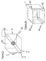
- FIG. 1 is shown generally an example of a percussive drum 1.
- the drum 1 has six faces or sides 2 and is cuboid in shape.
- the drum 1 is a cube.
- Each side 2 of the drum 1 therefore has four corners 3, which may be overlaid by corner protectors 4.
- Said corner protectors 4 are preferably made of leather, a material which is characterised by a desirable combination of protective resilience and aesthetic qualities, although other materials may also be appropriate.
- the percussion drum 1 has a side length of approximately 15inches (or 40cm).
- Each of the sides 2 is made of medium density fibre board (MDF), although wood, plywood, chipboard and other wood derivatives may be used, as well as synthetics, metals or other materials deemed appropriate - for example for their tonal properties.
- MDF medium density fibre board
- Individual sides 2 of a single percussion drum 1 may be made of different materials.
- the sides 2 may be of different individual densities, as well as or instead of different thicknesses.
- the sides are attached to one another via screws, nails, adhesive or a combination of the above.
- Each of the faces 6, 8 comprises one or more perforations 10.
- Perforations 10 penetrate all the way through the live face 6 upon which they are situated. The size, number and formation of perforations 10 may be altered as desired to adjust the volume and the timbre of a given live face 6.
- the preferred configuration 12 of perforations 10 is shown at figure 1 . It has been found that this configuration 12 produces an optimal balance of timbre, tonality and loudness.
- the live faces 6 are perforated so that sounds produced by striking a face 6 would cause the face 6 to reverberate and that reverberation will be reflected internally then out via the perforations or holes 10 formed in the face 6.
- the dead faces 8 thereby advantageously provide a location for other features of the drum 1 as well as a means for resting the drum 1 on a surface without compromising its playability.
- the dead faces 8 may carry a handle 14, as shown in figure 1 .
- handle 14 is carved into or otherwise fashioned from the material of a dead face 8.
- the carving in of handle 14 is of course only one means of attaching such a feature to a drum 1.
- handle 14 is added in a discreet fashion and in a manner which does not interfere with the ergonomics and aesthetics of the design of the drum 1. Whilst there may, in some examples, be two handles 14; one in each dead face, the location of the handle according to the invention is shown at figure 6 .
- the drum 1 at figure 6 embodying the invention comprises several advantageous preferred features.
- the first advantageous feature is that the dead faces 8 are perpendicular to each other and so form an edge 50.
- the key advantage to this comes when playing the drum 1; the dead faces 8 may be held between the user's knees, allowing easy access to the remaining four live faces 6.
- the second key feature is the placing of handle 14a at edge 50 - in the edge at which the dead faces 8 meet.
- Handle 14a comprises a recess 52 scooped or carved from dead faces 8. Said recess 52 is spanned by a bar 54 which may either be formed from wood left over from forming recess 52, or through the subsequent addition of a separate part, which may be of plastics or metal. Whilst the placement of handle 14a in this manner provides a generally desirable carrying means, with the aesthetic and ergonomic advantages identified as afforded by recessed handles above, a particular advantage is shown at figure 7 ; namely that two cubes 1 may be arranged in such a way that the handles 14a face each other, thus facilitating the easy carrying by the user of two cubes with one hand. Its location also improves its mechanical properties. The drum will withstand greater stresses and strains due to the location of the handle in this position when compared to the middle of a face of a drum.
- jack 16 also present on the visible dead face 8 is jack 16.
- This jack 16 allows electro acoustic versions of the drum 1 to be attached to other audio equipment, notably amplification and processing means.
- Another example of jack 16 may be replaced or supplemented by a radio transmitter and/or a preamp. Purely acoustic versions of the drum 1 are also envisaged.
- a side 2 of the percussive drum 1, preferably a dead face 8 incorporates a removal central region which is a tight fit in the rest of the given side 2 and incorporates a thumbnail undercut region to allow it to be prised out of its surrounding side 2 area when the user desires to remove it.
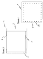
- FIG. 2 shows an example of drum 1.
- an acoustic to electric transducer such as a microphone 20 or pickup is suspended in central cavity 22 formed by the sides 2 of the drum 1.
- the microphone 20 is held there by virtue of beam 24 which runs diagonally between opposing internal corners 50 of the drum 1.
- This example shows microphone 20 suspended by a single beam 24 although clearly multiple beams are possible.
- the beam 24 could be substituted with a taut wire.
- the suspension of the microphone 20 with a beam 24 is advantageous in that said microphone 20 is placed at the centre of cavity 22, that is to say equidistant from each of the sides 4 of the drum 1 with the result that no live face 6 is unintentionally louder than the others.
- a further advantage in suspending the microphone thus is to isolate said microphone 20 from the vibrations caused by striking the drum.
- a still further advantage of so mounting the microphone 20 is that it is less likely to be shaken from position.
- An advantage of using a beam 24 as the means of suspending the microphone is that the beam 24 may be hollow, thereby providing a passage (not shown) to connect the microphone 20 to the jack 16 (shown in figure 1 ) or similar. Access to the microphone 20 may optionally be by way of removal of the handle 14 (shown in figure 1 ), which need not be integrated; in some preferred embodiments, but may instead be of metal, and may be releasably attached to the drum 1 by screws, or a releasable attachment means, or may clip in.
- drum 1 with internal bracing 80 which in this embodiment comprises a series of elongate blocks of wood, placed parallel to the edges 82 of the drum 1.
- the blocks may be made of alternative materials, but wood is favoured.
- the internal bracing 80 forms a frame, upon which sides 2 may be mounted to form the drum 1.
- the sides 2 are joined to the frame via screws, bolts, pegs or the like, with filler or adhesive.
- the screws bolts pegs or the like join the bracing 80 through apertures 84 formed in the sides 2 themselves.
- any remaining gaps in the apertures 84 are filled with filler.
- the filler is preferably applied so as to form a flat plane with the rest of face 2.
- the use of bracing 80 advantageously provides a more resilient means of construction than merely attaching the sides on to one another.
- Figure 3 shows a drum 1 in cross section. It illustrates how in each of the live faces 6 is of a different thickness.
- the variation of thickness is advantageous because different thicknesses of live faces 6 will produce different notes and tonal qualities. It is possible to produce a variety of tuned drums wherein the different thicknesses of the live faces 6 comprise a scale or arpeggio in a given key.
- FIG 4 is shown a side 2 of a drum 1.
- the side 2 is attached to other sides (not shown) via screws 26.
- the screws 26 are spaced regularly around the perimeter of a given side.
- the use of screws 26 to attach sides 2 together has been shown to be a particularly sturdy and desirable manner of so attaching. Other means, allowing for given panels to be readily removable and replaceable, are also envisaged.
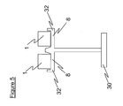
- FIG 5 is a stand 30 on which two drums 1 are mounted.
- the dead faces 8 of the drums are in contact with the stand.
- the stand's drum holding portions 32 features a means for interfacing with the handles 14 of the drums 1, providing for example releasable locking means.
- a drum 60 there is shown a drum 60.
- the drum 60 is adapted to be a gaming controller, and may, via means known to the skilled man, be made compatible with any gaming system. Alternatively it may be a stand alone gaming system, with built in or uploadable programmes - the drum 60 may have processing and data storage means (neither of which are shown) to facilitate this.
- the drum 60 has a plurality of sides 62, at least one of which comprises a sensor 64. Such a configuration could be embodied as a midi controller, or similar such interface, for triggering synthetic and sampled drum sounds.
- interactions with the sensors may bring about sonic and visual responses from the drum, by way of a sound source such as a speaker 66 which may either be internal, or external as shown, or a light source, which may take the form of one or more lights 68.
- a sound source such as a speaker 66 which may either be internal, or external as shown, or a light source, which may take the form of one or more lights 68.
- the sides 62 are translucent, and are underlit by lights 68.
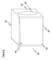
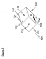
- Drum 100 is a cube. Of the six faces 102, three are shown. The drum 100 is orientated on the page in the manner in which it would be played; drum 100 has an apex 104 and a nadir 106. The two faces 102 on either side of the nadir 106 are dead faces; although it is the case they may be hit. The two faces 102 adjacent nadir 106 are made of much thicker material than the other faces so that when they are hit they make a much quieter sound - they resonate a lot less than the live faces, being relatively inflexible; more rigid. Of the remaining four faces 102 there are two made of plywood and two of MDF.
- Drum 100 has a handle 108, which is mounted into the two faces adjacent the nadir 106. In this preferred embodiment all faces have perforations 110. Also in this embodiment a live face adjacent the apex 104 carries a jack socket 112 for connecting the internal microphone (not shown) to an external amplification source.
Landscapes
- Physics & Mathematics (AREA)
- Engineering & Computer Science (AREA)
- Acoustics & Sound (AREA)
- Multimedia (AREA)
- Electrophonic Musical Instruments (AREA)
Description
- The invention relates to percussion instruments and is specifically concerned with percussion instruments in the form of a drum. Also within the ambit of the invention is a stand for such a drum.
- This application is related to UK Patent Application
GB 2464727 - Percussion drums are conventionally designed to produce their sound by striking the drum's playing surface with drumsticks or, in some cases, with the fingers and palm of the player. Such conventional drums are also designed either to be mounted on a stand or to be held between the player's knees. In each case, they are therefore relatively formal items and, whilst they can be carried from site to site, they are not designed or adapted to be readily manipulated during play.
- The well known need of many people nowadays to have something to manipulate is taken care of conventionally by flexible and relatively small multi-timbed and/or differentially shaped finger-handled objects - often given the generic name "executive toys" - which can be twisted, turned, and otherwise played with to give some repeated measure of relief to the user. These act as an effective outlet for excess energy as well as, or instead of, pent-up frustration on the part of the user.
- None of these disparate objects provides any outlet at all for the natural and indeed overwhelming urge in many people to have something on which to tap out a rhythm, repetitively, for sheer enjoyment and which is large enough to give a pleasingly reverberating sound whilst being sufficiently compact and relatively light weight to be picked up, carried around, and manipulated and swivelled between the player's outstretched hands as the rhythmic striking of the object gathers pace.
- Same known percussion instruments are disclosed in the following documents.
-
DE3503866A1 HOSHINO GAKKI -
FR2902921A1 -
W096.13027A1 -
DE3205136A1 WILL GEB KLEIN -
US3136201A LANG ET AL -
US5292276A MANOLO -
JP11173876A -
US538075A CARNES ET AL - http://www.amazon.co.uk/PINTOY-5202-DRUM/dp/B0000AC98D - "Drum by Pintoy"
- http://www,fledglings.org.uk/content/view/136/1/
- In addition, the following stand out as of particular note:
-
DE202007000686U1 FRANZEN CHRISTOPH comprises a cajon drum with a pentagonal or hexagonal cross section. It is made of wood and has both live and dead faces. It has no handle but does comprise sound holes in its dead faces, the surrounds of which may be used as such. It is designed for sedentary play, optimally by two people at once. -
DE202006008418U1 MEYER MARKUS is a modified cajon drum, modified so as to produce an extended range of sounds. To this end, it comprises a bass chamber and a snare with a separate snare chamber with a divider between the two chambers. It has no dedicated handle since as a cajon, it is designed for sedentary play, but similar to the above, the surround of the reflection channel may be used as a sort of handle. -
DE202006012202 PRIEL GERHARD is a cajon with a plurality of snares - also disclosed is a compatible stand. -
US2008034944 ASPLAND MARK comprises a cuboidal drum with a sound altering device comprising a plurality of internal snares which can be brought into contact with the internal surface of the resonant chamber of the drum. This drum is essentially a bass drum and is envisaged to be placed on the floor and in preferred embodiments interfaced with via a pedal. -
US5814747 RAMSELL CRAIG comprises a tubular percussion instrument which is longitudinally rigid and radially flexible. The tube resonates and thus produces a tone. Multi-textured percussion blocks with which to strike the tube are also provided - the different textures allow for the production of different timbres. - In a first broad independent aspect, the invention provides a percussion instrument in the form of a drum wherein each striking face has a different percussive property wherein the percussion instrument is rectangular parallelepiped or cuboid in shape, comprises four live striking faces, and two dead faces, which are not for striking, and further comprising an integrally formed, recessed handle the percussion instrument being chacterised in that the dead faces are located adjacent one another, being in touching contact such that the contact between the two dead faces comprises an edge and wherein the handle is located at that edge.
- In addition to having different resistance to a strike force, the differing faces may have different tonal properties or achieve different playing effects. This configuration is particularly advantageous because it allows an increase in playing options and/or effects whilst presenting three or more faces which can withstand repetitive percussions throughout the use of the instrument. It also provides an improvement in the distribution of impacts throughout use and therefore increases its resistance to percussions damage which all instruments eventually suffer from. It also provides a particularly compact instrument for the level of versatility achieved.
- This configuration of four live striking faces and two dead faces which are not for striking is particularly advantageous in terms of distribution of forces in the instrument.
- The faces may be of a material selected from the group comprising: MDF, ply, wood, metals and polymers. A combination of a number of faces of MDF and a number of faces of ply wood provides advantageous structural and musical range properties.
- The faces may optionally be formed as a wall with sides which are adjacent to and/or in abutment with the sides of the wall of neighbouring faces. This allows the faces to collectively form substantially the entire exposed surface of the parallelepiped. This further improves the collective strength and toughness of the instrument.
- The feature of the handle is particularly advantageous since it reduces the required components and simplifies its requirements for assembly.
- One particularly advantageous option is achieved by employing striking faces of different or differing thickness. This may for example allow one or more faces to be dead faces in use which may be of greater thickness than other faces. This would further strengthen the configuration as opposed to conventional approaches. In this configuration, the dead face(s) can contribute significantly to the overall rigidity of the instrument. This would therefore minimise the necessary structural components. A further preferred optional configuration is achieved by employing striking faces of differing construction in order to obtain different tones or playing effects. This may allow faces to be configured to have greater wear resistance dependent on predetermined strike patterns. A further particularly advantageous option is achieved by employing striking faces of differing density. This is particularly versatile in terms of construction since it would allow portions of support structures to be identical irrespective of the faces which are secured to the support structures whilst still providing the variation in tonal properties.
- In a further subsidiary aspect, each striking face has a different density.
- In a further subsidiary aspect, the invention further comprises a cavity, the cavity containing an acoustic to electric transducer, the electric transducer being suspended within the cavity. This configuration is particularly advantageous in terms of capture of sound. It is further advantageous when a diagonally extending beam is employed since it achieves extra structural strength and the ability to place the pick up in an optimum position for picking sound irrespective of the live faces struck.
- In a further subsidiary aspect, the electric transducer is suspended substantially at the centre of the cavity. This is particularly advantageous to pick up sound irrespective of the live faces struck.
- In a further subsidiary aspect, the electric transducer is suspended by one or more beams. This adds extra rigidity to the instrument.
- In a further broad independent aspect, the invention provides a percussion instrument in the form of a drum substantially as described herein with reference to and as illustrated in the accompanying drawings.
- In a further broad independent aspect, the invention provides a system comprising a percussion instrument according to any of the preceding claims and a stand specifically adapted to support said percussion instrument, wherein the stand further comprises an interface for interfacing with a handle of a percussion instrument.
- In a presently preferred practical embodiment of the invention, the drum is a cube-shaped drum with a side length lying within the
range 12 inches to 18 inches (approximately 30cm to 45cm) and preferably a side length of approximately 15 inches (say 40cm) and its faces are perforated so as to give, to a user of the drum, a pleasingly varied reverberative sound output as he taps, slaps, strikes with the heel of his palm, and otherwise assaults the drum manually in an extempore and usually spontaneous manner. - Other aspects of the invention will become apparent from reading the description which now follows with reference to the accompanying drawings forming part of this specification. The scope of the invention as such is defined in the numbered claims at the end of the description text.
- The invention will now be described with reference to the following figures, of which:
-
Figure 1 is a perspective view of a percussive drum, -
Figure 2 is a perspective view of the inside of a percussive drum, -
Figure 2a is a cross-sectional perspective view showing the bracing inside the percussive drum. -
Figure 3 is a side view of a percussive drum, -
Figure 4 is a cross sectional side view of a percussive drum, and -
Figure 5 is a side elevational view of a stand holding two percussive drums embodying the invention. -
Figure 6 is a perspective view of an embodiment of a percussive drum of the invention. -
Figure 7 is a perspective view of a plurality of percussive drums, in a further embodiment of the invention. -
Figure 8 is a perspective view of a drum in the form of a controller. -
Figure 9 is a perspective view of a further percussive drum of the invention. - This invention comprises a percussion instrument in the form of a drum being rectangular parallelepiped which is preferably cuboid in shape and having four live striking faces, wherein each striking face is of a different thickness or density. The invention further comprises a stand specifically adapted to support a percussion instrument of that form.
- At
figure 1 is shown generally an example of apercussive drum 1. Thedrum 1 has six faces orsides 2 and is cuboid in shape. In this example, embodiment, thedrum 1 is a cube. Eachside 2 of thedrum 1 therefore has fourcorners 3, which may be overlaid bycorner protectors 4. Saidcorner protectors 4 are preferably made of leather, a material which is characterised by a desirable combination of protective resilience and aesthetic qualities, although other materials may also be appropriate. - In this example, four of the
sides 2 are live drum faces 6, or striking faces (including two which are not shown) and two of thesides 2 are dead faces 8 (including one which is not shown). Thepercussion drum 1 has a side length of approximately 15inches (or 40cm). Each of thesides 2 is made of medium density fibre board (MDF), although wood, plywood, chipboard and other wood derivatives may be used, as well as synthetics, metals or other materials deemed appropriate - for example for their tonal properties.Individual sides 2 of asingle percussion drum 1 may be made of different materials. Thesides 2 may be of different individual densities, as well as or instead of different thicknesses. The sides are attached to one another via screws, nails, adhesive or a combination of the above. - Each of the
faces more perforations 10.Perforations 10 penetrate all the way through thelive face 6 upon which they are situated. The size, number and formation ofperforations 10 may be altered as desired to adjust the volume and the timbre of a givenlive face 6. Thepreferred configuration 12 ofperforations 10 is shown atfigure 1 . It has been found that thisconfiguration 12 produces an optimal balance of timbre, tonality and loudness. The live faces 6 are perforated so that sounds produced by striking aface 6 would cause theface 6 to reverberate and that reverberation will be reflected internally then out via the perforations or holes 10 formed in theface 6. - In some examples, the dead faces 8 thereby advantageously provide a location for other features of the
drum 1 as well as a means for resting thedrum 1 on a surface without compromising its playability. The dead faces 8 may carry ahandle 14, as shown infigure 1 . Here, handle 14 is carved into or otherwise fashioned from the material of adead face 8. The carving in ofhandle 14 is of course only one means of attaching such a feature to adrum 1. However, by integratinghandles 14 into the dead faces 8, handle 14 is added in a discreet fashion and in a manner which does not interfere with the ergonomics and aesthetics of the design of thedrum 1. Whilst there may, in some examples, be twohandles 14; one in each dead face, the location of the handle according to the invention is shown atfigure 6 . - The
drum 1 atfigure 6 embodying the invention comprises several advantageous preferred features. The first advantageous feature is that the dead faces 8 are perpendicular to each other and so form anedge 50. The key advantage to this comes when playing thedrum 1; the dead faces 8 may be held between the user's knees, allowing easy access to the remaining fourlive faces 6. - The second key feature is the placing of
handle 14a at edge 50 - in the edge at which the dead faces 8 meet.Handle 14a comprises arecess 52 scooped or carved from dead faces 8. Saidrecess 52 is spanned by a bar 54 which may either be formed from wood left over from formingrecess 52, or through the subsequent addition of a separate part, which may be of plastics or metal. Whilst the placement ofhandle 14a in this manner provides a generally desirable carrying means, with the aesthetic and ergonomic advantages identified as afforded by recessed handles above, a particular advantage is shown atfigure 7 ; namely that twocubes 1 may be arranged in such a way that thehandles 14a face each other, thus facilitating the easy carrying by the user of two cubes with one hand. Its location also improves its mechanical properties. The drum will withstand greater stresses and strains due to the location of the handle in this position when compared to the middle of a face of a drum. - Returning to
figure 1 , also present on the visibledead face 8 isjack 16. Thisjack 16 allows electro acoustic versions of thedrum 1 to be attached to other audio equipment, notably amplification and processing means. Another example ofjack 16 may be replaced or supplemented by a radio transmitter and/or a preamp. Purely acoustic versions of thedrum 1 are also envisaged. - Optionally, a
side 2 of thepercussive drum 1, preferably adead face 8, incorporates a removal central region which is a tight fit in the rest of the givenside 2 and incorporates a thumbnail undercut region to allow it to be prised out of itssurrounding side 2 area when the user desires to remove it. This gives access to the interior of thedrum 1 enabling adjusting of features associated with an interior, or internal cavity, as discussed below. -
Figure 2 shows an example ofdrum 1. Inside thedrum 1 an acoustic to electric transducer such as amicrophone 20 or pickup is suspended in central cavity 22 formed by thesides 2 of thedrum 1. Themicrophone 20 is held there by virtue of beam 24 which runs diagonally between opposinginternal corners 50 of thedrum 1. This example showsmicrophone 20 suspended by a single beam 24 although clearly multiple beams are possible. The beam 24 could be substituted with a taut wire. The suspension of themicrophone 20 with a beam 24 is advantageous in that saidmicrophone 20 is placed at the centre of cavity 22, that is to say equidistant from each of thesides 4 of thedrum 1 with the result that nolive face 6 is unintentionally louder than the others. A further advantage in suspending the microphone thus is to isolate saidmicrophone 20 from the vibrations caused by striking the drum. A still further advantage of so mounting themicrophone 20 is that it is less likely to be shaken from position. An advantage of using a beam 24 as the means of suspending the microphone is that the beam 24 may be hollow, thereby providing a passage (not shown) to connect themicrophone 20 to the jack 16 (shown infigure 1 ) or similar. Access to themicrophone 20 may optionally be by way of removal of the handle 14 (shown infigure 1 ), which need not be integrated; in some preferred embodiments, but may instead be of metal, and may be releasably attached to thedrum 1 by screws, or a releasable attachment means, or may clip in. - At
figure 2a , there is showndrum 1 with internal bracing 80, which in this embodiment comprises a series of elongate blocks of wood, placed parallel to theedges 82 of thedrum 1. The blocks may be made of alternative materials, but wood is favoured. The internal bracing 80 forms a frame, upon which sides 2 may be mounted to form thedrum 1. Thesides 2 are joined to the frame via screws, bolts, pegs or the like, with filler or adhesive. In preferred embodiments, the screws bolts pegs or the like join the bracing 80 throughapertures 84 formed in thesides 2 themselves. When thesides 2 are joined, any remaining gaps in theapertures 84 are filled with filler. The filler is preferably applied so as to form a flat plane with the rest offace 2. The use of bracing 80 advantageously provides a more resilient means of construction than merely attaching the sides on to one another. -
Figure 3 shows adrum 1 in cross section. It illustrates how in each of the live faces 6 is of a different thickness. The variation of thickness is advantageous because different thicknesses oflive faces 6 will produce different notes and tonal qualities. It is possible to produce a variety of tuned drums wherein the different thicknesses of the live faces 6 comprise a scale or arpeggio in a given key. - At
figure 4 is shown aside 2 of adrum 1. Theside 2 is attached to other sides (not shown) via screws 26. Thescrews 26 are spaced regularly around the perimeter of a given side. The use ofscrews 26 to attachsides 2 together has been shown to be a particularly sturdy and desirable manner of so attaching. Other means, allowing for given panels to be readily removable and replaceable, are also envisaged. - At
figure 5 is astand 30 on which twodrums 1 are mounted. The dead faces 8 of the drums are in contact with the stand. The stand'sdrum holding portions 32 features a means for interfacing with thehandles 14 of thedrums 1, providing for example releasable locking means. - At
figure 8 , there is shown adrum 60. Thedrum 60 is adapted to be a gaming controller, and may, via means known to the skilled man, be made compatible with any gaming system. Alternatively it may be a stand alone gaming system, with built in or uploadable programmes - thedrum 60 may have processing and data storage means (neither of which are shown) to facilitate this. Thedrum 60 has a plurality ofsides 62, at least one of which comprises asensor 64. Such a configuration could be embodied as a midi controller, or similar such interface, for triggering synthetic and sampled drum sounds. - Returning to the gaming controller; contingent on the game being played, interactions with the sensors may bring about sonic and visual responses from the drum, by way of a sound source such as a
speaker 66 which may either be internal, or external as shown, or a light source, which may take the form of one ormore lights 68. In a particularly preferred example, thesides 62 are translucent, and are underlit bylights 68. - At
Figure 9 is shown a particularly preferred embodiment of the invention.Drum 100 is a cube. Of the six faces 102, three are shown. Thedrum 100 is orientated on the page in the manner in which it would be played;drum 100 has an apex 104 and anadir 106. The two faces 102 on either side of thenadir 106 are dead faces; although it is the case they may be hit. The two faces 102adjacent nadir 106 are made of much thicker material than the other faces so that when they are hit they make a much quieter sound - they resonate a lot less than the live faces, being relatively inflexible; more rigid. Of the remaining fourfaces 102 there are two made of plywood and two of MDF. The thinnest of the two MDF live faces is of substantially the same thickness as the thinner of the two plywood faces and the thicker of the two MDF faces are substantially the same thickness as the thicker of the two plywood faces. In this case then, there are three different thicknesses of faces, counting the dead faces.Drum 100 has ahandle 108, which is mounted into the two faces adjacent thenadir 106. In this preferred embodiment all faces haveperforations 110. Also in this embodiment a live face adjacent the apex 104 carries ajack socket 112 for connecting the internal microphone (not shown) to an external amplification source. - The scope of the invention is now formally defined in the numbered claims which follow.
Claims (8)
- A percussion instrument in the form of a drum (1) wherein each striking face (6) has a different percussive property wherein the percussion instrument is rectangular parallelepiped or cuboid in shape, comprises four live striking faces (6), and two dead faces (8), which are not for striking, and further comprising an integrally formed, recessed handle (14a), the percussion instrument being characterised in that the dead faces (8) are located adjacent one another, being in touching contact such that the contact between the two dead faces comprises an edge (50) and wherein the handle (14a) is located at that edge (50).
- A percussion instrument according to claim 1, wherein each striking face has a different thickness.
- A percussion instrument according to either claim 1 or claim 2, wherein each striking face has a different density.
- A percussion instrument according to any of the preceding claims, wherein each striking face is substantially identical in surface area.
- A percussion instrument according to any of the previous claims, further comprising a cavity (22), the cavity containing an acoustic to electric transducer (20), the electric transducer being suspended within the cavity.
- A percussion instrument according to claim 5, wherein the electric transducer is suspended substantially at the centre of the cavity.
- A percussion instrument according to either of claims 5 and 6, wherein the electric transducer is suspended by one or more beams (24).
- A system comprising a percussion instrument according to any of the preceding claims and a stand specifically adapted to support said percussion instrument, wherein the stand (30) further comprises an interface for interfacing with a handle of a percussion instrument.
Applications Claiming Priority (2)
| Application Number | Priority Date | Filing Date | Title |
|---|---|---|---|
| GB0908708A GB2462503B (en) | 2009-05-21 | 2009-05-21 | Percussion instrument |
| PCT/GB2010/050836 WO2010133892A2 (en) | 2009-05-21 | 2010-05-21 | Percussion instrument |
Publications (2)
| Publication Number | Publication Date |
|---|---|
| EP2433277A2 EP2433277A2 (en) | 2012-03-28 |
| EP2433277B1 true EP2433277B1 (en) | 2013-07-10 |
Family
ID=40862721
Family Applications (1)
| Application Number | Title | Priority Date | Filing Date |
|---|---|---|---|
| EP10721549.3A Not-in-force EP2433277B1 (en) | 2009-05-21 | 2010-05-21 | Percussion instrument |
Country Status (6)
| Country | Link |
|---|---|
| US (1) | US8735703B2 (en) |
| EP (1) | EP2433277B1 (en) |
| ES (1) | ES2430971T3 (en) |
| GB (1) | GB2462503B (en) |
| PT (1) | PT2433277E (en) |
| WO (1) | WO2010133892A2 (en) |
Cited By (2)
| Publication number | Priority date | Publication date | Assignee | Title |
|---|---|---|---|---|
| CN108470557A (en) * | 2016-12-18 | 2018-08-31 | 韦雪 | A kind of LED desk lamp |
| RU2737945C1 (en) * | 2020-03-04 | 2020-12-07 | Мария Михайловна Торицына | Modular musical instrument |
Families Citing this family (21)
| Publication number | Priority date | Publication date | Assignee | Title |
|---|---|---|---|---|
| US8609970B2 (en) * | 2008-08-12 | 2013-12-17 | Randall May International Incorporated | Suspended drum microphone system |
| US8779263B2 (en) | 2010-03-04 | 2014-07-15 | Kmc Music, Inc. | Channeled shaker |
| ITGE20110129A1 (en) * | 2011-11-15 | 2013-05-16 | Gregorio Pier Paolo De | FIXING MECHANISM FOR FRONT PANEL, TO BE APPLIED TO MUSICAL INSTRUMENT WITH PERCUSSION, GENERALLY KNOWN AS CAJON |
| IT1403572B1 (en) * | 2010-12-17 | 2013-10-31 | Gregorio De | FIXING MECHANISM FOR MUSICAL INSTRUMENT WITH PARTICULARLY PERCUSSION FOR FLAMENCO, CARIBBEAN MUSIC, AFRO-PERUVIANA AND ETHNIC MUSIC. |
| WO2013026502A2 (en) * | 2010-12-17 | 2013-02-28 | De Gregorio Pier Paolo | Fastening mechanism for musical percussion instrument, particularly suitable for flamenco, caribbean, afro-peruvian and ethnic music |
| GB2487070A (en) * | 2011-01-06 | 2012-07-11 | Kevin Paul Jones | Stand for a cajon |
| US8481834B2 (en) * | 2011-09-15 | 2013-07-09 | Remo, Inc. | Cajon with textured applications |
| US9263010B2 (en) * | 2012-08-13 | 2016-02-16 | Joshua Trask | Multi-tonal box drum kit |
| DE112014004890T5 (en) * | 2013-10-25 | 2016-08-11 | Sergio Bonsignore | Snares-Cajóninstrument |
| US10015571B2 (en) | 2013-12-10 | 2018-07-03 | Randall May International, Inc. | Motorized microphone rail |
| US20150187344A1 (en) * | 2013-12-31 | 2015-07-02 | Daniel Vea James | Percussion Box |
| WO2015138644A1 (en) * | 2014-03-11 | 2015-09-17 | Eric Alexander | Cajon |
| WO2016027154A1 (en) * | 2014-08-22 | 2016-02-25 | Shaanti Rohan | Constructive music |
| US9711122B1 (en) * | 2015-10-08 | 2017-07-18 | Jason Van Pelt | Acoustic stomp box percussion device |
| USD786337S1 (en) * | 2015-11-13 | 2017-05-09 | Drum Workshop, Inc. | Shaped percussion instrument |
| JP6758042B2 (en) * | 2015-12-02 | 2020-09-23 | ローランド株式会社 | Percussion instruments and cajon |
| RU2626982C2 (en) * | 2016-01-26 | 2017-08-02 | Владимир Кузьмич Люткус | Clog box |
| GB2573678B (en) | 2017-01-17 | 2023-01-18 | Drum Workshop Inc | Percussion instrument with adjustable auxiliary device |
| US20190001231A1 (en) * | 2017-07-01 | 2019-01-03 | Schmick, Llc | Portable Configurable Music Station |
| CN115317888A (en) * | 2021-03-19 | 2022-11-11 | 王磊 | Many materials can temper dice of hearing |
| US12205561B2 (en) * | 2022-04-20 | 2025-01-21 | Milo Martin | Percussion musical instrument |
Citations (1)
| Publication number | Priority date | Publication date | Assignee | Title |
|---|---|---|---|---|
| US5814747A (en) * | 1994-10-24 | 1998-09-29 | Ramsell; Craig | Percussion instrument capable of producing a musical tone |
Family Cites Families (20)
| Publication number | Priority date | Publication date | Assignee | Title |
|---|---|---|---|---|
| US2900453A (en) * | 1957-04-16 | 1959-08-18 | Associated Engineering & Equip | Microphone |
| US2858724A (en) * | 1958-06-09 | 1958-11-04 | Frederick J Troppe | Multiple-tone drum |
| US3136201A (en) | 1962-10-17 | 1964-06-09 | Lang Morris | Drum |
| DE3205136A1 (en) | 1982-02-12 | 1983-08-18 | geb. Klein Katharina 6630 Saarlouis Will | Sound body, sound tower, sound stepping |
| JPS60169689U (en) | 1984-04-20 | 1985-11-11 | 星野楽器株式会社 | drum |
| US5159139A (en) | 1990-06-13 | 1992-10-27 | Evans Products, Inc. | Drumhead with overtone suppression |
| US5292276A (en) | 1993-08-02 | 1994-03-08 | Manalo Teresita D | Early childhood learning toy |
| US5385075A (en) | 1994-03-22 | 1995-01-31 | Carnes; Ben | Percussion instrument |
| JP3803187B2 (en) | 1997-12-15 | 2006-08-02 | 株式会社コルグ | Electric drum |
| GB2334366B (en) * | 1998-02-16 | 2002-04-10 | Christopher Daniel Mccartney | Drum |
| US7547836B2 (en) * | 2001-07-09 | 2009-06-16 | Kevin Matthew Reed | Musical drum |
| NZ552255A (en) * | 2004-05-27 | 2011-03-31 | Mark Aspland | Drum with alteration of range of sounds when struck externally, and internal drum stick that partially rotates to strike |
| US7498500B2 (en) | 2006-01-19 | 2009-03-03 | Rtom Corporation | Drumhead assembly with improved rebound |
| DE202006008418U1 (en) * | 2006-05-22 | 2006-09-07 | Meyer, Markus | Modified drawer for percussion has resonant chamber, which is divided into snare chamber and a bass chamber whereby rear part of base chamber facing rear wall is equipped with a slit part |
| DE202006012202U1 (en) * | 2006-08-09 | 2006-09-28 | Priel, Gerhard | Cajon, has holder to fix snare rug segments in interior of housing, such that rug segments lie in inner side of wall segments at preset angle of incidence, where rug segments consist of springs whose lower ends are fixed on bar in holder |
| DE202007000686U1 (en) * | 2007-01-11 | 2007-05-24 | Franzen, Christoph | Cajon e.g. for percussion instrument, is made from wood housing and has two neighboring side panels designed as impact surfaces |
| FR2902921A1 (en) | 2007-05-03 | 2007-12-28 | Nicolas Robert | Sound drum body for emitting sound, has case with shape of equilateral triangle, and head pushed by support triangle for producing tension that permits to emit sound, where tension is produced by using applicators |
| DE102007032204B3 (en) * | 2007-07-11 | 2008-10-02 | Roland Meinl Musikinstrumente Gmbh & Co. Kg | Cajon, has striking surface bulged out in convex form, and fastened to base body by punctiform fastening element that is not provided in such manner that upper corner region steeps out from upper front wall |
| US7807910B1 (en) * | 2008-04-23 | 2010-10-05 | Nicholas Clement Berardo | Musical drum with multiple playing surfaces and a seat for the player |
| GB2464727A (en) | 2008-10-24 | 2010-04-28 | Dion Dublin | Percussion instrument with peripherally divided tactile wall regions |
-
2009
- 2009-05-21 GB GB0908708A patent/GB2462503B/en not_active Expired - Fee Related
-
2010
- 2010-05-21 PT PT107215493T patent/PT2433277E/en unknown
- 2010-05-21 EP EP10721549.3A patent/EP2433277B1/en not_active Not-in-force
- 2010-05-21 US US13/320,793 patent/US8735703B2/en not_active Expired - Fee Related
- 2010-05-21 WO PCT/GB2010/050836 patent/WO2010133892A2/en not_active Ceased
- 2010-05-21 ES ES10721549T patent/ES2430971T3/en active Active
Patent Citations (1)
| Publication number | Priority date | Publication date | Assignee | Title |
|---|---|---|---|---|
| US5814747A (en) * | 1994-10-24 | 1998-09-29 | Ramsell; Craig | Percussion instrument capable of producing a musical tone |
Cited By (9)
| Publication number | Priority date | Publication date | Assignee | Title |
|---|---|---|---|---|
| CN108470557A (en) * | 2016-12-18 | 2018-08-31 | 韦雪 | A kind of LED desk lamp |
| CN108520738A (en) * | 2016-12-18 | 2018-09-11 | 乌鲁木齐九品芝麻信息科技有限公司 | Accompaniment apparatus and accompaniment method |
| CN108597486A (en) * | 2016-12-18 | 2018-09-28 | 丁永新 | A kind of intelligent accompaniment apparatus |
| CN108597485A (en) * | 2016-12-18 | 2018-09-28 | 常州爱上学教育科技有限公司 | Intelligent accompaniment apparatus and its working method |
| CN108648739A (en) * | 2016-12-18 | 2018-10-12 | 常州爱上学教育科技有限公司 | Intelligent accompaniment apparatus |
| CN108799894A (en) * | 2016-12-18 | 2018-11-13 | 丁永新 | LED desk lamp device and its working method |
| CN108799894B (en) * | 2016-12-18 | 2020-11-20 | 江苏金黄光智慧照明研究院有限公司 | LED table lamp device and working method thereof |
| CN108597486B (en) * | 2016-12-18 | 2020-12-15 | 丁永新 | Intelligent accompaniment device |
| RU2737945C1 (en) * | 2020-03-04 | 2020-12-07 | Мария Михайловна Торицына | Modular musical instrument |
Also Published As
| Publication number | Publication date |
|---|---|
| US20120132058A1 (en) | 2012-05-31 |
| WO2010133892A2 (en) | 2010-11-25 |
| US8735703B2 (en) | 2014-05-27 |
| EP2433277A2 (en) | 2012-03-28 |
| GB0908708D0 (en) | 2009-07-01 |
| GB2462503A (en) | 2010-02-17 |
| WO2010133892A3 (en) | 2011-07-21 |
| PT2433277E (en) | 2013-10-17 |
| GB2462503B (en) | 2010-06-30 |
| ES2430971T3 (en) | 2013-11-22 |
Similar Documents
| Publication | Publication Date | Title |
|---|---|---|
| EP2433277B1 (en) | Percussion instrument | |
| EP1751739B1 (en) | An improved drum | |
| EP2571017B1 (en) | Musical instrument with textured applications | |
| US8802962B2 (en) | Foot actuated percussion board | |
| US8487170B2 (en) | Percussion instrument | |
| US4901617A (en) | Hand-held percussion instrument | |
| US5323678A (en) | Hand-held percussion musical instrument comprising elongate tube shaped as a ring, incorporating dividers, and incoporating contained sound-generating elements | |
| US9263019B2 (en) | Percussion instrument and method of manufacture | |
| JP7159220B2 (en) | small drum kit | |
| JP6758042B2 (en) | Percussion instruments and cajon | |
| US7528312B1 (en) | Drum for striking upwardly and method therefor | |
| WO2013116317A1 (en) | Percussion instrument with interior porting | |
| US20110185877A1 (en) | Stringed musical instrument | |
| RU121394U1 (en) | SHOCK MUSICAL INSTRUMENT | |
| WO2010046680A1 (en) | Percussion instrument | |
| CN213635331U (en) | Novel drum simulating sound of sand bucket and military drum | |
| KR101973910B1 (en) | Dadeumi type Percussion instrument | |
| KR200348847Y1 (en) | An electromagnetic drum having output function of sound effect | |
| CN113160776A (en) | Percussion organ and percussion hammer with multiple sound zones and sound cavity | |
| US20160293146A1 (en) | Tamber Stick | |
| EP0729627A1 (en) | Percussion instrument with strings | |
| HK1108057B (en) | An improved drum | |
| WO2016160015A1 (en) | The tamber stick |
Legal Events
| Date | Code | Title | Description |
|---|---|---|---|
| PUAI | Public reference made under article 153(3) epc to a published international application that has entered the european phase |
Free format text: ORIGINAL CODE: 0009012 |
|
| 17P | Request for examination filed |
Effective date: 20111215 |
|
| AK | Designated contracting states |
Kind code of ref document: A2 Designated state(s): AL AT BE BG CH CY CZ DE DK EE ES FI FR GB GR HR HU IE IS IT LI LT LU LV MC MK MT NL NO PL PT RO SE SI SK SM TR |
|
| DAX | Request for extension of the european patent (deleted) | ||
| 17Q | First examination report despatched |
Effective date: 20120911 |
|
| GRAP | Despatch of communication of intention to grant a patent |
Free format text: ORIGINAL CODE: EPIDOSNIGR1 |
|
| GRAS | Grant fee paid |
Free format text: ORIGINAL CODE: EPIDOSNIGR3 |
|
| GRAA | (expected) grant |
Free format text: ORIGINAL CODE: 0009210 |
|
| AK | Designated contracting states |
Kind code of ref document: B1 Designated state(s): AL AT BE BG CH CY CZ DE DK EE ES FI FR GB GR HR HU IE IS IT LI LT LU LV MC MK MT NL NO PL PT RO SE SI SK SM TR |
|
| REG | Reference to a national code |
Ref country code: GB Ref legal event code: FG4D |
|
| REG | Reference to a national code |
Ref country code: CH Ref legal event code: EP Ref country code: AT Ref legal event code: REF Ref document number: 621360 Country of ref document: AT Kind code of ref document: T Effective date: 20130715 |
|
| REG | Reference to a national code |
Ref country code: IE Ref legal event code: FG4D |
|
| REG | Reference to a national code |
Ref country code: DE Ref legal event code: R096 Ref document number: 602010008448 Country of ref document: DE Effective date: 20130912 |
|
| REG | Reference to a national code |
Ref country code: PT Ref legal event code: SC4A Free format text: AVAILABILITY OF NATIONAL TRANSLATION Effective date: 20131010 |
|
| PG25 | Lapsed in a contracting state [announced via postgrant information from national office to epo] |
Ref country code: SI Free format text: LAPSE BECAUSE OF FAILURE TO SUBMIT A TRANSLATION OF THE DESCRIPTION OR TO PAY THE FEE WITHIN THE PRESCRIBED TIME-LIMIT Effective date: 20130710 |
|
| REG | Reference to a national code |
Ref country code: ES Ref legal event code: FG2A Ref document number: 2430971 Country of ref document: ES Kind code of ref document: T3 Effective date: 20131122 |
|
| REG | Reference to a national code |
Ref country code: AT Ref legal event code: MK05 Ref document number: 621360 Country of ref document: AT Kind code of ref document: T Effective date: 20130710 |
|
| REG | Reference to a national code |
Ref country code: NL Ref legal event code: VDEP Effective date: 20130710 |
|
| REG | Reference to a national code |
Ref country code: LT Ref legal event code: MG4D |
|
| PG25 | Lapsed in a contracting state [announced via postgrant information from national office to epo] |
Ref country code: NO Free format text: LAPSE BECAUSE OF FAILURE TO SUBMIT A TRANSLATION OF THE DESCRIPTION OR TO PAY THE FEE WITHIN THE PRESCRIBED TIME-LIMIT Effective date: 20131010 Ref country code: BE Free format text: LAPSE BECAUSE OF FAILURE TO SUBMIT A TRANSLATION OF THE DESCRIPTION OR TO PAY THE FEE WITHIN THE PRESCRIBED TIME-LIMIT Effective date: 20130710 Ref country code: LT Free format text: LAPSE BECAUSE OF FAILURE TO SUBMIT A TRANSLATION OF THE DESCRIPTION OR TO PAY THE FEE WITHIN THE PRESCRIBED TIME-LIMIT Effective date: 20130710 Ref country code: SE Free format text: LAPSE BECAUSE OF FAILURE TO SUBMIT A TRANSLATION OF THE DESCRIPTION OR TO PAY THE FEE WITHIN THE PRESCRIBED TIME-LIMIT Effective date: 20130710 Ref country code: CY Free format text: LAPSE BECAUSE OF FAILURE TO SUBMIT A TRANSLATION OF THE DESCRIPTION OR TO PAY THE FEE WITHIN THE PRESCRIBED TIME-LIMIT Effective date: 20130814 Ref country code: HR Free format text: LAPSE BECAUSE OF FAILURE TO SUBMIT A TRANSLATION OF THE DESCRIPTION OR TO PAY THE FEE WITHIN THE PRESCRIBED TIME-LIMIT Effective date: 20130710 Ref country code: AT Free format text: LAPSE BECAUSE OF FAILURE TO SUBMIT A TRANSLATION OF THE DESCRIPTION OR TO PAY THE FEE WITHIN THE PRESCRIBED TIME-LIMIT Effective date: 20130710 Ref country code: IS Free format text: LAPSE BECAUSE OF FAILURE TO SUBMIT A TRANSLATION OF THE DESCRIPTION OR TO PAY THE FEE WITHIN THE PRESCRIBED TIME-LIMIT Effective date: 20131110 |
|
| PG25 | Lapsed in a contracting state [announced via postgrant information from national office to epo] |
Ref country code: GR Free format text: LAPSE BECAUSE OF FAILURE TO SUBMIT A TRANSLATION OF THE DESCRIPTION OR TO PAY THE FEE WITHIN THE PRESCRIBED TIME-LIMIT Effective date: 20131011 Ref country code: LV Free format text: LAPSE BECAUSE OF FAILURE TO SUBMIT A TRANSLATION OF THE DESCRIPTION OR TO PAY THE FEE WITHIN THE PRESCRIBED TIME-LIMIT Effective date: 20130710 Ref country code: PL Free format text: LAPSE BECAUSE OF FAILURE TO SUBMIT A TRANSLATION OF THE DESCRIPTION OR TO PAY THE FEE WITHIN THE PRESCRIBED TIME-LIMIT Effective date: 20130710 Ref country code: FI Free format text: LAPSE BECAUSE OF FAILURE TO SUBMIT A TRANSLATION OF THE DESCRIPTION OR TO PAY THE FEE WITHIN THE PRESCRIBED TIME-LIMIT Effective date: 20130710 Ref country code: NL Free format text: LAPSE BECAUSE OF FAILURE TO SUBMIT A TRANSLATION OF THE DESCRIPTION OR TO PAY THE FEE WITHIN THE PRESCRIBED TIME-LIMIT Effective date: 20130710 |
|
| PG25 | Lapsed in a contracting state [announced via postgrant information from national office to epo] |
Ref country code: CY Free format text: LAPSE BECAUSE OF FAILURE TO SUBMIT A TRANSLATION OF THE DESCRIPTION OR TO PAY THE FEE WITHIN THE PRESCRIBED TIME-LIMIT Effective date: 20130710 |
|
| PG25 | Lapsed in a contracting state [announced via postgrant information from national office to epo] |
Ref country code: DK Free format text: LAPSE BECAUSE OF FAILURE TO SUBMIT A TRANSLATION OF THE DESCRIPTION OR TO PAY THE FEE WITHIN THE PRESCRIBED TIME-LIMIT Effective date: 20130710 Ref country code: CZ Free format text: LAPSE BECAUSE OF FAILURE TO SUBMIT A TRANSLATION OF THE DESCRIPTION OR TO PAY THE FEE WITHIN THE PRESCRIBED TIME-LIMIT Effective date: 20130710 Ref country code: SK Free format text: LAPSE BECAUSE OF FAILURE TO SUBMIT A TRANSLATION OF THE DESCRIPTION OR TO PAY THE FEE WITHIN THE PRESCRIBED TIME-LIMIT Effective date: 20130710 Ref country code: EE Free format text: LAPSE BECAUSE OF FAILURE TO SUBMIT A TRANSLATION OF THE DESCRIPTION OR TO PAY THE FEE WITHIN THE PRESCRIBED TIME-LIMIT Effective date: 20130710 Ref country code: RO Free format text: LAPSE BECAUSE OF FAILURE TO SUBMIT A TRANSLATION OF THE DESCRIPTION OR TO PAY THE FEE WITHIN THE PRESCRIBED TIME-LIMIT Effective date: 20130710 |
|
| PLBE | No opposition filed within time limit |
Free format text: ORIGINAL CODE: 0009261 |
|
| STAA | Information on the status of an ep patent application or granted ep patent |
Free format text: STATUS: NO OPPOSITION FILED WITHIN TIME LIMIT |
|
| 26N | No opposition filed |
Effective date: 20140411 |
|
| REG | Reference to a national code |
Ref country code: DE Ref legal event code: R097 Ref document number: 602010008448 Country of ref document: DE Effective date: 20140411 |
|
| PG25 | Lapsed in a contracting state [announced via postgrant information from national office to epo] |
Ref country code: LU Free format text: LAPSE BECAUSE OF FAILURE TO SUBMIT A TRANSLATION OF THE DESCRIPTION OR TO PAY THE FEE WITHIN THE PRESCRIBED TIME-LIMIT Effective date: 20140521 |
|
| REG | Reference to a national code |
Ref country code: CH Ref legal event code: PL |
|
| GBPC | Gb: european patent ceased through non-payment of renewal fee |
Effective date: 20140521 |
|
| PG25 | Lapsed in a contracting state [announced via postgrant information from national office to epo] |
Ref country code: CH Free format text: LAPSE BECAUSE OF NON-PAYMENT OF DUE FEES Effective date: 20140531 Ref country code: MC Free format text: LAPSE BECAUSE OF FAILURE TO SUBMIT A TRANSLATION OF THE DESCRIPTION OR TO PAY THE FEE WITHIN THE PRESCRIBED TIME-LIMIT Effective date: 20130710 Ref country code: LI Free format text: LAPSE BECAUSE OF NON-PAYMENT OF DUE FEES Effective date: 20140531 |
|
| REG | Reference to a national code |
Ref country code: IE Ref legal event code: MM4A |
|
| PG25 | Lapsed in a contracting state [announced via postgrant information from national office to epo] |
Ref country code: IE Free format text: LAPSE BECAUSE OF NON-PAYMENT OF DUE FEES Effective date: 20140521 |
|
| REG | Reference to a national code |
Ref country code: FR Ref legal event code: PLFP Year of fee payment: 6 |
|
| PG25 | Lapsed in a contracting state [announced via postgrant information from national office to epo] |
Ref country code: GB Free format text: LAPSE BECAUSE OF NON-PAYMENT OF DUE FEES Effective date: 20140521 |
|
| PGFP | Annual fee paid to national office [announced via postgrant information from national office to epo] |
Ref country code: DE Payment date: 20150626 Year of fee payment: 6 Ref country code: ES Payment date: 20150504 Year of fee payment: 6 Ref country code: PT Payment date: 20150427 Year of fee payment: 6 |
|
| PGFP | Annual fee paid to national office [announced via postgrant information from national office to epo] |
Ref country code: FR Payment date: 20150528 Year of fee payment: 6 Ref country code: IT Payment date: 20150506 Year of fee payment: 6 |
|
| PG25 | Lapsed in a contracting state [announced via postgrant information from national office to epo] |
Ref country code: MT Free format text: LAPSE BECAUSE OF FAILURE TO SUBMIT A TRANSLATION OF THE DESCRIPTION OR TO PAY THE FEE WITHIN THE PRESCRIBED TIME-LIMIT Effective date: 20130710 |
|
| PG25 | Lapsed in a contracting state [announced via postgrant information from national office to epo] |
Ref country code: SM Free format text: LAPSE BECAUSE OF FAILURE TO SUBMIT A TRANSLATION OF THE DESCRIPTION OR TO PAY THE FEE WITHIN THE PRESCRIBED TIME-LIMIT Effective date: 20130710 |
|
| PG25 | Lapsed in a contracting state [announced via postgrant information from national office to epo] |
Ref country code: BG Free format text: LAPSE BECAUSE OF FAILURE TO SUBMIT A TRANSLATION OF THE DESCRIPTION OR TO PAY THE FEE WITHIN THE PRESCRIBED TIME-LIMIT Effective date: 20130710 |
|
| PG25 | Lapsed in a contracting state [announced via postgrant information from national office to epo] |
Ref country code: TR Free format text: LAPSE BECAUSE OF FAILURE TO SUBMIT A TRANSLATION OF THE DESCRIPTION OR TO PAY THE FEE WITHIN THE PRESCRIBED TIME-LIMIT Effective date: 20130710 Ref country code: HU Free format text: LAPSE BECAUSE OF FAILURE TO SUBMIT A TRANSLATION OF THE DESCRIPTION OR TO PAY THE FEE WITHIN THE PRESCRIBED TIME-LIMIT; INVALID AB INITIO Effective date: 20100521 |
|
| REG | Reference to a national code |
Ref country code: DE Ref legal event code: R119 Ref document number: 602010008448 Country of ref document: DE |
|
| PG25 | Lapsed in a contracting state [announced via postgrant information from national office to epo] |
Ref country code: IT Free format text: LAPSE BECAUSE OF NON-PAYMENT OF DUE FEES Effective date: 20160521 Ref country code: PT Free format text: LAPSE BECAUSE OF NON-PAYMENT OF DUE FEES Effective date: 20161121 |
|
| REG | Reference to a national code |
Ref country code: FR Ref legal event code: ST Effective date: 20170131 |
|
| PG25 | Lapsed in a contracting state [announced via postgrant information from national office to epo] |
Ref country code: DE Free format text: LAPSE BECAUSE OF NON-PAYMENT OF DUE FEES Effective date: 20161201 Ref country code: FR Free format text: LAPSE BECAUSE OF NON-PAYMENT OF DUE FEES Effective date: 20160531 |
|
| PG25 | Lapsed in a contracting state [announced via postgrant information from national office to epo] |
Ref country code: ES Free format text: LAPSE BECAUSE OF NON-PAYMENT OF DUE FEES Effective date: 20160522 |
|
| REG | Reference to a national code |
Ref country code: ES Ref legal event code: FD2A Effective date: 20180626 |
|
| PG25 | Lapsed in a contracting state [announced via postgrant information from national office to epo] |
Ref country code: MK Free format text: LAPSE BECAUSE OF FAILURE TO SUBMIT A TRANSLATION OF THE DESCRIPTION OR TO PAY THE FEE WITHIN THE PRESCRIBED TIME-LIMIT Effective date: 20130710 |
|
| PG25 | Lapsed in a contracting state [announced via postgrant information from national office to epo] |
Ref country code: AL Free format text: LAPSE BECAUSE OF FAILURE TO SUBMIT A TRANSLATION OF THE DESCRIPTION OR TO PAY THE FEE WITHIN THE PRESCRIBED TIME-LIMIT Effective date: 20130710 |