EP2432404B1 - Thrombus retrieval device - Google Patents
Thrombus retrieval device Download PDFInfo
- Publication number
- EP2432404B1 EP2432404B1 EP09796561.0A EP09796561A EP2432404B1 EP 2432404 B1 EP2432404 B1 EP 2432404B1 EP 09796561 A EP09796561 A EP 09796561A EP 2432404 B1 EP2432404 B1 EP 2432404B1
- Authority
- EP
- European Patent Office
- Prior art keywords
- delivery tube
- thrombus
- engaging elements
- thrombus engaging
- wire
- Prior art date
- Legal status (The legal status is an assumption and is not a legal conclusion. Google has not performed a legal analysis and makes no representation as to the accuracy of the status listed.)
- Active
Links
Images


Classifications
-
- A—HUMAN NECESSITIES
- A61—MEDICAL OR VETERINARY SCIENCE; HYGIENE
- A61B—DIAGNOSIS; SURGERY; IDENTIFICATION
- A61B17/00—Surgical instruments, devices or methods
- A61B17/22—Implements for squeezing-off ulcers or the like on inner organs of the body; Implements for scraping-out cavities of body organs, e.g. bones; for invasive removal or destruction of calculus using mechanical vibrations; for removing obstructions in blood vessels, not otherwise provided for
- A61B17/221—Gripping devices in the form of loops or baskets for gripping calculi or similar types of obstructions
-
- A—HUMAN NECESSITIES
- A61—MEDICAL OR VETERINARY SCIENCE; HYGIENE
- A61B—DIAGNOSIS; SURGERY; IDENTIFICATION
- A61B17/00—Surgical instruments, devices or methods
- A61B17/22—Implements for squeezing-off ulcers or the like on inner organs of the body; Implements for scraping-out cavities of body organs, e.g. bones; for invasive removal or destruction of calculus using mechanical vibrations; for removing obstructions in blood vessels, not otherwise provided for
- A61B17/22031—Gripping instruments, e.g. forceps, for removing or smashing calculi
-
- A—HUMAN NECESSITIES
- A61—MEDICAL OR VETERINARY SCIENCE; HYGIENE
- A61B—DIAGNOSIS; SURGERY; IDENTIFICATION
- A61B17/00—Surgical instruments, devices or methods
- A61B17/32—Surgical cutting instruments
- A61B17/320016—Endoscopic cutting instruments, e.g. arthroscopes, resectoscopes
-
- A—HUMAN NECESSITIES
- A61—MEDICAL OR VETERINARY SCIENCE; HYGIENE
- A61M—DEVICES FOR INTRODUCING MEDIA INTO, OR ONTO, THE BODY; DEVICES FOR TRANSDUCING BODY MEDIA OR FOR TAKING MEDIA FROM THE BODY; DEVICES FOR PRODUCING OR ENDING SLEEP OR STUPOR
- A61M29/00—Dilators with or without means for introducing media, e.g. remedies
-
- A—HUMAN NECESSITIES
- A61—MEDICAL OR VETERINARY SCIENCE; HYGIENE
- A61B—DIAGNOSIS; SURGERY; IDENTIFICATION
- A61B17/00—Surgical instruments, devices or methods
- A61B17/32—Surgical cutting instruments
- A61B17/3205—Excision instruments
- A61B17/32056—Surgical snare instruments
-
- A—HUMAN NECESSITIES
- A61—MEDICAL OR VETERINARY SCIENCE; HYGIENE
- A61B—DIAGNOSIS; SURGERY; IDENTIFICATION
- A61B17/00—Surgical instruments, devices or methods
- A61B2017/00831—Material properties
- A61B2017/00867—Material properties shape memory effect
-
- A—HUMAN NECESSITIES
- A61—MEDICAL OR VETERINARY SCIENCE; HYGIENE
- A61B—DIAGNOSIS; SURGERY; IDENTIFICATION
- A61B17/00—Surgical instruments, devices or methods
- A61B17/22—Implements for squeezing-off ulcers or the like on inner organs of the body; Implements for scraping-out cavities of body organs, e.g. bones; for invasive removal or destruction of calculus using mechanical vibrations; for removing obstructions in blood vessels, not otherwise provided for
- A61B17/22031—Gripping instruments, e.g. forceps, for removing or smashing calculi
- A61B2017/22034—Gripping instruments, e.g. forceps, for removing or smashing calculi for gripping the obstruction or the tissue part from inside
Definitions
- the present invention relates to a snare for the retrieval of occluding bodies from lumen.
- the invention has particular, although not exclusive relevance to the in-vivo retrieval of intracranial soft thrombi.
- Ischeamic cerebrovascual accidents can be caused by full or partial occlusion of the brain's arterial blood vessels, for example by intracranial thrombi or emboli, or by thrombi in the dural venous sinuses that drain blood from the brain.
- the removal of occluding bodies from the cerebral vasculature may be achieved by pharmacological means, for example by thrombolysis, or by mechanical means, for example by physically breaking a thrombus or embolus into a number of pieces prior to its removal.
- the breaking into pieces of an occluding body can be deleterious as dislodged parts may travel through the cerebral vasculature and subsequently form emboli themselves. Blocking and/or suction means are therefore required to ensure that dislodged parts are safely collected.
- the need for blocking and/or suction means limits the size of vessels in which such an approach can be employed and precludes its application for many of the small and tortuous intracranial blood vessels, for example the branch vessels of the circle of Willis or middle cerebral artery, and arteries arising from the distal vertebral and basilar arteries.
- Document US 2004/220604 A1 discloses a tissue separation device comprising a delivery tube with at least one side hole oriented radially and one or more wires for each side hole, each wire being movable radially of the delivery tube between a retracted configuration in which it is retained within the delivery tube and a deployed configuration in which it projects from the delivery tube through the side hole.
- the present invention provides a device for the retrieval of a thrombus from a vessel, the device comprising: a delivery tube with at least one side hole oriented radially; and one or more thrombus engaging elements for each side hole, each thrombus engaging element comprising a wire and being movable radially of the delivery tube between a retracted configuration in which it is retained within the delivery tube and a deployed configuration in which it projects from the delivery tube through the side hole.
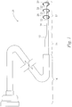
- FIG 1 shows a perspective view of a flexible catheter 10 having a thrombus retrieval section 12, a pushing section 14, and a delivery and removal section 16.
- the retrieval section 12 comprises a flexible delivery tube 18 of small diameter, and three thrombus engaging elements, in this case curly wires 20, made of an elastic material and having a predetermined shape.
- the curly wires 20 are shown in a deployed configuration in which their distal ends project radially from respective holes 22 of the flexible delivery tube 18. In this configuration, the distal ends are unconstrained and so take their undeformed shapes which correspond to approximate semicircles in the radial plane.
- the pushing section 14 is flexible and is fixedly coupled to, and has a larger diameter than, the retrieving section 12.
- the delivery and removal section 16 is a flexible tube having an internal diameter that is large enough for both the pushing section 14 and the retrieval section 12 to be retracted therethrough when the retrieval section 12 is in the deployed configuration and is ensnaring a thrombus.
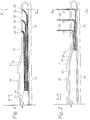
- Figure 2 shows a longitudinal cross-section of the flexible catheter 10 of Figure 1 when in the deployed configuration.
- the proximal ends of the curly wires 20 are retained within the flexible delivery tube 18 and are fixedly coupled, for example by welding, soldering, or gluing, to a pushing member 23.
- the pushing member 23 is slidable within an outer tube 24 of the pushing section 14 in a proximal-distal direction (as indicated by arrow P-D of Figure 2 ) and has a larger cross-sectional area than the curly wires 20 so as to facilitate the transmission of a pushing force from a surgeon, or another operator of the flexible catheter 10, to the curly wires 20.
- the outer tube 24 of the pushing section 14 has a stop surface 26 arranged to abut with a corresponding stop surface 28 of the pushing member 23 to prevent the pushing member 23 pushing the curly wires 20 out of the holes 22 by more than a predetermined amount.
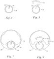
- Figure 3 shows a transverse cross-section along line A-A of Figure 2 of the retrieval section 12 in the deployed configuration.
- the distal end of a curly wire 20 can be seen projecting from a hole 22 in the flexible delivery tube 18.
- the distal end of the curly wire 20 is unconstrained by the flexible delivery tube 18, it is in its undeformed shape which in this case corresponds to a semicircle-like loop in the transverse (or radial) plane of the flexible delivery tube 18.
- Figure 4 shows a longitudinal cross-section of the flexible catheter 10 in a retracted configuration.
- the pushing member 23 is less advanced in the distal direction with respect to the outer tube 24 of the pushing section 14 than in the deployed configuration and the distal ends of the curly wires 20 are entirely contained within the flexible delivery tube 18;
- Figure 5 which shows a transverse cross-section along line B-B of Figure 4 of the retrieval section 12, illustrates this further.
- the curly wires 20 have been elastically deformed from their undeformed, curly, state and, due to flexible delivery tube 18, are constrained to be relatively straight.
- the pushing member 23 of the flexible catheter 10 is set up so that the distal ends of the curly wires 20 are adjacent their respective holes 22, but do not project therefrom.
- Pushing member 23 is then locked with respect to the outer tube 24 of the pushing section 14 in the retracted configuration by a locking mechanism (not shown) to prevent unintended deployment of the curly wires 20 during delivery of the retrieval section 12 to the site of the thrombus.
- a percutaneous incision is made in the patient, for example to access the carotid, subclavian, or femoral artery.
- the flexible catheter 10 in the retracted configuration is then introduced via the incision into the patient's arterial system and advanced to the site of the thrombus in a two-stage procedure under the guidance of an imaging system, for example X-ray, ultrasound, magnetic resonance imaging, or any combination thereof.
- Contrast enhancement agents may be employed in order to facilitate identification of the location of the thrombus.
- the delivery and removal section 16 which has a larger cross-sectional profile than those of the pushing and retrieval sections 14, 12, is advanced towards the site of the thrombus until the blood vessels through which it is being advanced narrow to prevent further advancement - typically this occurs 10-15cm away from the thrombus.
- the pushing and retrieval sections 14, 12 are advanced with respect to the delivery and removal section 16 until the tip of the flexible delivery tube 18 of the retrieval section 12 is next (or proximally adjacent) to the thrombus.
- the flexible catheter 10 is further advanced so that the retrieval section 12 lies to one side of (or is radially adjacent to) the thrombus and the holes 22 face (or open in the direction of) the thrombus. If the thrombus totally occludes the blood vessel then the retrieval section 12 is advanced through the thrombus to reach such a position. As the flexible catheter 10 is in the retracted configuration, it has a small cross-sectional profile and can therefore easily be advanced to such a position.
- Figure 6 shows the flexible delivery tube 18 inside a blood vessel 30 having a thrombus 32.
- Figure 7 shows a cross-sectional view along line C-C of Figure 6 and further illustrates how the flexible delivery tube 18 lies to one side of the thrombus.
- the locking mechanism (not shown) that prevents movement of the pushing member 23 with respect to the outer tube 24 of the pushing section 14 is released and the pushing member 22 is advanced in the distal direction until the stop surface 28 of the pushing member 23 contacts the stop surface 26 of the outer tube 24 of the pushing section 14. This pushes the distal ends of the curly wires through their respective holes 22. As the curly wires 20 pass through the holes 22, they spring back into their undeformed shapes and advance into the thrombus 32 thereby ensnaring it.
- the amount of force required to push the curly wires into the thrombus 32 is relatively small.
- the chance of the thrombus breaking up is significantly reduced.
- Figure 8 shows the flexible delivery tube 18 inside the blood vessel 30 and to one side of the thrombus 32; however, in Figure 8 the curly wires 20 are shown in the deployed configuration having advanced into the thrombus 32.
- Figure 9 shows a cross-sectional view along line D-D of Figure 8 and further illustrates how the curly wires 20 have advanced into the thrombus 32.
- the locking mechanism (not shown) that prevents movement of the pushing member 23 with respect to the outer tube 24 of the pushing section 14 is locked to prevent the curly wires 20 from retracting from the thrombus 32 during removal of the flexible catheter 10.
- the ensnared thrombus is then removed from the vessel 30 by retracting the retrieval and pushing sections 12, 14 into the delivery and removal section 16. Once the retrieval section 12 and the thrombus 32 that it ensnares are retracted into the delivery and removal section 16, the risk of parts of the ensnared thrombus breaking off during retraction of the flexible catheter 10 from the vascular system is reduced and the flexible catheter 10 is withdrawn from the patient.
- the above described apparatus has a small cross-sectional area and may be used for vessels having a smaller diameter than would be possible for techniques that break thrombi into a number of pieces.
- the apparatus could equally be employed to remove emboli and/or be used in the venous cerebral vasculature.
- the apparatus could be employed for the removal of thrombi or emboli from other parts of the body, for example from the coronary or pulmonary arteries and/or the branch vessels thereof.
- the pushing section 14 has a larger diameter than the retrieving section 12; as another possibility, the pushing section may have a diameter about the same as the diameter of the retrieving section 12 thereby increasing the range of thrombi that the retrieving section 12 can reach. In such an embodiment, the tapered shoulder 15 of the retrieving section 12 would not be present.
- the motion of the pushing member 23 in the proximal direction may also be constrained by a pair of complimentary stopping surfaces (not shown) arranged to prevent the curly wires 20 from being retracted with respect to the holes 22 by more than a predetermined amount - thereby ensuring that the curly wires 20 do not lose alignment with their respective holes 22.
- the pushing member 23 may be keyed to the outer tube 24 of the pushing section 14 to prevent twisting of the outer tube 24 from causing misalignment between the curly wires 20 and their respective holes 22 as could occur during advancement of the flexible catheter 10 to the thrombus.
- the flexible delivery tube 18 may further comprise one or more guide portions (not shown) arranged to guide the curly wires to their respective holes 22.
- guide portions may comprise one or more wire-specific tubes within which each curly wire 20 slides, or may comprise one or more internal baffles to direct the passage of the curly wires 20.
- the presence of guide portions may allow the curly wires 20 to be withdrawn more than would otherwise be possible without them becoming misaligned from their respective holes 22, and may facilitate assembly of the flexible catheter 10.
- curly wires 20 may be bonded to one another.
- the curly wires 20 may form a single component with only the distal tips of the wires projecting from a main body thereof.
- the curly wires 20 may have a shape such that, upon deployment, they curl back on themselves so that their distal ends enter into one or more holes in the flexible delivery tube 18 leaving only intermediate portions of the curly wires outside of the flexible delivery tube 18.
- the outer diameter of the flexible delivery tube 18 is preferably in the range 3Fr to 2Fr (where the diameter in millimetres is determined by dividing the Fr size by 3), and more preferably 2.2Fr.
- the outer diameters of the curly wires 20 need to be such that they are able to fit within the flexible delivery tube 18; they may, for example, be as small as 0.06mm.
- the flexible catheter 10 preferably has between three and five curly wires 20, and more preferably three.
- the curly wires 20 may have cross-sectional profiles that are circular, or they may have one or more flattened portions to increase the surface area of the curly wires that is available for engagement with thrombi.
- the cross-sectional profiles of the curly wires 20 may be shaped and/or oriented so as to reduce the risk of the curly wires 20 digging into vessel walls during deployment and/or retraction, for example, the cross-sectional profile may be chosen so as to not comprise any corners or highly curved portions.
- Figures 10, 11, and 12 show example cross-sectional profiles of the curly wires 20 and indicate with arrow 'R' the direction in which the curly wire 20 will be pulled when the retrieval section 12 is retracted into the delivery and removal section 16.
- the leading edge of the profile of Figure 11 is a semicircle 34 of large diameter and so, like the profile of Figure 1 , will not present surrounding blood vessel walls with sharp edges during retraction.
- the profile of Figure 11 also comprises a pair of flat edges 36 for increasing the surface area of the curly wire 20 that is available for gripping with thrombi.
- the profile of Figure 12 is shown next to a portion of vessel wall 30, and is oriented with respect to the vessel wall 30 such that, upon retraction in direction R, if the curly wire 20 encounters a protrusion 31 or change in direction of the vessel wall 30, the edge 38 of the curly wire 20 acts to push the curly wire 20 in direction A away from the protrusion 31 wall thereby reducing the risk of the curly wire digging into the vessel wall 30 or the protrusion 31.
- the surfaces of the curly wires 20 may be textured or may have a rough coating. Additionally or alternatively, the curly wires 20 may be provided with a drug eluting coating, for example a thrombolytic agent to facilitate pushing of the curly wires 20 into the thrombus, or a sticky coating to help retain thrombi during retraction.
- a drug eluting coating for example a thrombolytic agent to facilitate pushing of the curly wires 20 into the thrombus, or a sticky coating to help retain thrombi during retraction.
- Figure 13 shows an end view of the retrieval section of an alternative embodiment in which the curly wires 20 are offset from one another by 120 degrees - in such an embodiment, the distal ends of the curly wires 20 could be all in the same radial plane, or could be set apart from one another along the longitudinal axis of the retrieval section.
- the holes 22 are positioned in the range 10 to 15mm from the distal tip of the retrieval section 12.
- Figure 14 shows an end view of the retrieval section 12 of another alternative embodiment in which the curly wires 20 are configured so that, when in the deployed configuration, they loop about the flexible delivery tube 18 so as to have a circular shape.
- the retrieval section 12 of this embodiment is positioned in a blood vessel 30 adjacent to a thrombus 32 (as shown in Figure 15 ) and the curly wires 20 are deployed, they loop around the flexible delivery tube 18 and ensnare the thrombus 32 irrespective of the orientation of the holes 22. Accordingly, this embodiment obviates any need to rotationally orient the flexible delivery tube 18 prior to deployment.
- the retrieval sections 12 of the embodiments of Figures 1 to 9 and 14 and 15 are preferably advanced so that they lie to one side of the thrombus 32 prior to deployment of the curly wires 20, as another possibility, the retrieval sections 12 may be advanced so that they are radially surrounded by the thrombus 32 prior to deployment of the curly wires 20.
- the retrieval section 12 is preferably advanced so that it is radially surrounded by the thrombus 32 prior to deployment of the curly wires 20; however, as another possibility the retrieval section 12 may be advanced so that it lies to one side of the thrombus 32 prior to deployment of the curly wires 20.
- thrombus engaging elements that are curly wires having semi circular or circular shapes in the transverse plane
- other shapes not limited to the transverse plane could instead be employed, for example a distal-proximal oriented corkscrew shape or a pig's tail shape.
- the curly wires 20 should have sufficient rigidity to be able to retain their shape when the retrieval section 12 is retracted along with a thrombus.
- Curly wires 20 are preferably made of a material that exhibits shape memory such as NiTi or CuZnAl that has been treated to have the desired shape (for example to have a semi-circular shape at their distal ends).
- the curly wires 40 may be made of an elastic non-memory material such as surgical grade steel.
- Retrieval section 12 may further comprise one or more 'clot catching' threads, fibres or materials (not shown) attached to its distal end to provide clotting points for any debris that is created during thrombus removal.
- Retrieval section 12 may further comprise positioning means for ensuring that, prior to being brought alongside the thrombus, the flexible delivery tube 18 is located against the vessel wall and that the holes 22 are correctly oriented.
- positioning means may comprise, for example, a balloon element positioned on one side of the flexible delivery tube 18 to push the flexible delivery tube 18 to the vessel wall.
- the positioning means may comprise an additional hole (not shown) in the flexible delivery tube 18 and an additional curly wire (not shown) that could be deployed just prior to the flexible delivery tube 18 being brought alongside the thrombus so as to push the flexible delivery tube 18 against the vessel wall.
- the additional curly wire could be deployable by the pushing member 23 which could push the additional curly wire out of the additional hole from the retracted configuration to an in-between 'positioning' configuration.
- the flexible delivery tube 18 would then be pushed up against the vessel wall and could be advanced to the thrombus before the pushing member 23 is further advanced to its deployed configuration.
- the flexible delivery tube 18 or the outer tube 24 of the pushing section 14 may comprise one or more markers than can be seen by the imaging system used to guide it to the location of the thrombus.
- the flexible delivery tube 18 may comprise one or more radiopaque bands.
- the markers may be positioned or shaped so as to allow an operator to determine the orientation of the holes 22 of the flexible delivery tube 18 from the imaging system. If the holes 22 themselves are observable by the imaging system, their shape and/or position may be used to orient the holes 22.
- the curly wires 22 themselves may comprise radiopaque materials to enable, when in the undeployed configuration, the orientation of the holes 22 to be determined.
- the pushing and retrieval sections 14, 12 may be positioned prior to the delivery and removal section 16.
- the flexible delivery tube 18 has an internal lumen (not shown) for a wire guide; in use a wire guide is positioned adjacent to the thrombus before the flexible catheter 10 is delivered thereover.
Landscapes
- Health & Medical Sciences (AREA)
- Life Sciences & Earth Sciences (AREA)
- Surgery (AREA)
- General Health & Medical Sciences (AREA)
- Veterinary Medicine (AREA)
- Engineering & Computer Science (AREA)
- Biomedical Technology (AREA)
- Animal Behavior & Ethology (AREA)
- Heart & Thoracic Surgery (AREA)
- Public Health (AREA)
- Orthopedic Medicine & Surgery (AREA)
- Nuclear Medicine, Radiotherapy & Molecular Imaging (AREA)
- Medical Informatics (AREA)
- Molecular Biology (AREA)
- Vascular Medicine (AREA)
- Anesthesiology (AREA)
- Hematology (AREA)
- Surgical Instruments (AREA)
- Media Introduction/Drainage Providing Device (AREA)
Description
- The present invention relates to a snare for the retrieval of occluding bodies from lumen. The invention has particular, although not exclusive relevance to the in-vivo retrieval of intracranial soft thrombi.
- Ischeamic cerebrovascual accidents can be caused by full or partial occlusion of the brain's arterial blood vessels, for example by intracranial thrombi or emboli, or by thrombi in the dural venous sinuses that drain blood from the brain.
- The removal of occluding bodies from the cerebral vasculature may be achieved by pharmacological means, for example by thrombolysis, or by mechanical means, for example by physically breaking a thrombus or embolus into a number of pieces prior to its removal.
- The breaking into pieces of an occluding body can be deleterious as dislodged parts may travel through the cerebral vasculature and subsequently form emboli themselves. Blocking and/or suction means are therefore required to ensure that dislodged parts are safely collected. The need for blocking and/or suction means limits the size of vessels in which such an approach can be employed and precludes its application for many of the small and tortuous intracranial blood vessels, for example the branch vessels of the circle of Willis or middle cerebral artery, and arteries arising from the distal vertebral and basilar arteries.
- Document
US 2004/220604 A1 discloses a tissue separation device comprising a delivery tube with at least one side hole oriented radially and one or more wires for each side hole, each wire being movable radially of the delivery tube between a retracted configuration in which it is retained within the delivery tube and a deployed configuration in which it projects from the delivery tube through the side hole. - The invention is described in claim 1. Preferred embodiments are described in the dependent claims.
- According to one aspect, the present invention provides a device for the retrieval of a thrombus from a vessel, the device comprising: a delivery tube with at least one side hole oriented radially; and one or more thrombus engaging elements for each side hole, each thrombus engaging element comprising a wire and being movable radially of the delivery tube between a retracted configuration in which it is retained within the delivery tube and a deployed configuration in which it projects from the delivery tube through the side hole.
- These and various other aspects of the invention will become apparent from the following detailed description which is given by way of example only and which is described with reference to the accompanying Figures in which:
-
-
Figure 1 shows a perspective view of catheter having a thrombus retrieval device arranged in a deployed configuration; -
Figure 2 shows a longitudinal cross-section of the retrieval device ofFigure 1 in the deployed configuration; -
Figure 3 shows a transverse cross-section of the retrieval device ofFigure 2 ; -
Figure 4 shows a longitudinal cross-section of the retrieval device ofFigure 1 arranged in a retracted configuration; -
Figure 5 shows a transverse cross-section of the retrieval device ofFigure 4 ; -
Figure 6 shows a longitudinal cross-section of the retrieval device ofFigure 1 arranged in the retracted configuration and positioned in a blood vessel adjacent to a thrombus; -
Figure 7 shows a transverse cross-section of the retrieval device ofFigure 6 ; -
Figure 8 shows a longitudinal cross-section of the retrieval device ofFigure 1 arranged in the deployed configuration and positioned in a blood vessel adjacent to a thrombus; -
Figure 9 shows a transverse cross-section of the retrieval device ofFigure 8 ; -
Figures 10, 11, and 12 show cross-sectional profiles of example curly wires of the retrieval device; -
Figure 13 shows an end view of the retrieval section of an alternative embodiment; -
Figure 14 shows an end view of the retrieval section of an alternative embodiment; and -
Figure 15 shows a transverse cross-section of the retrieval device ofFigure 14 arranged in the deployed configuration and positioned in a blood vessel adjacent to a thrombus. -
Figure 1 shows a perspective view of aflexible catheter 10 having athrombus retrieval section 12, a pushingsection 14, and a delivery andremoval section 16. Theretrieval section 12 comprises aflexible delivery tube 18 of small diameter, and three thrombus engaging elements, in this casecurly wires 20, made of an elastic material and having a predetermined shape. InFigure 1 thecurly wires 20 are shown in a deployed configuration in which their distal ends project radially fromrespective holes 22 of theflexible delivery tube 18. In this configuration, the distal ends are unconstrained and so take their undeformed shapes which correspond to approximate semicircles in the radial plane. The pushingsection 14 is flexible and is fixedly coupled to, and has a larger diameter than, the retrievingsection 12. The delivery andremoval section 16 is a flexible tube having an internal diameter that is large enough for both the pushingsection 14 and theretrieval section 12 to be retracted therethrough when theretrieval section 12 is in the deployed configuration and is ensnaring a thrombus. -
Figure 2 shows a longitudinal cross-section of theflexible catheter 10 ofFigure 1 when in the deployed configuration. The proximal ends of thecurly wires 20 are retained within theflexible delivery tube 18 and are fixedly coupled, for example by welding, soldering, or gluing, to a pushingmember 23. The pushingmember 23 is slidable within anouter tube 24 of the pushingsection 14 in a proximal-distal direction (as indicated by arrow P-D ofFigure 2 ) and has a larger cross-sectional area than thecurly wires 20 so as to facilitate the transmission of a pushing force from a surgeon, or another operator of theflexible catheter 10, to thecurly wires 20. Theouter tube 24 of the pushingsection 14 has astop surface 26 arranged to abut with acorresponding stop surface 28 of the pushingmember 23 to prevent the pushingmember 23 pushing thecurly wires 20 out of theholes 22 by more than a predetermined amount. -
Figure 3 shows a transverse cross-section along line A-A ofFigure 2 of theretrieval section 12 in the deployed configuration. The distal end of acurly wire 20 can be seen projecting from ahole 22 in theflexible delivery tube 18. As the distal end of thecurly wire 20 is unconstrained by theflexible delivery tube 18, it is in its undeformed shape which in this case corresponds to a semicircle-like loop in the transverse (or radial) plane of theflexible delivery tube 18. -
Figure 4 shows a longitudinal cross-section of theflexible catheter 10 in a retracted configuration. In the retracted configuration, the pushingmember 23 is less advanced in the distal direction with respect to theouter tube 24 of the pushingsection 14 than in the deployed configuration and the distal ends of thecurly wires 20 are entirely contained within theflexible delivery tube 18;Figure 5 , which shows a transverse cross-section along line B-B ofFigure 4 of theretrieval section 12, illustrates this further. In this configuration, thecurly wires 20 have been elastically deformed from their undeformed, curly, state and, due toflexible delivery tube 18, are constrained to be relatively straight. - In operation, prior to insertion into a patient's body, the pushing
member 23 of theflexible catheter 10 is set up so that the distal ends of thecurly wires 20 are adjacent theirrespective holes 22, but do not project therefrom. Pushingmember 23 is then locked with respect to theouter tube 24 of the pushingsection 14 in the retracted configuration by a locking mechanism (not shown) to prevent unintended deployment of thecurly wires 20 during delivery of theretrieval section 12 to the site of the thrombus. - To access the intracranial vessel from which a thrombus is to be removed, a percutaneous incision is made in the patient, for example to access the carotid, subclavian, or femoral artery. The
flexible catheter 10 in the retracted configuration is then introduced via the incision into the patient's arterial system and advanced to the site of the thrombus in a two-stage procedure under the guidance of an imaging system, for example X-ray, ultrasound, magnetic resonance imaging, or any combination thereof. Contrast enhancement agents may be employed in order to facilitate identification of the location of the thrombus. In the first stage of catheter advancement, the delivery andremoval section 16, which has a larger cross-sectional profile than those of the pushing andretrieval sections retrieval sections removal section 16 until the tip of theflexible delivery tube 18 of theretrieval section 12 is next (or proximally adjacent) to the thrombus. - Once the tip of the
flexible delivery tube 18 of theretrieval section 12 is next to the thrombus, theflexible catheter 10 is further advanced so that theretrieval section 12 lies to one side of (or is radially adjacent to) the thrombus and theholes 22 face (or open in the direction of) the thrombus. If the thrombus totally occludes the blood vessel then theretrieval section 12 is advanced through the thrombus to reach such a position. As theflexible catheter 10 is in the retracted configuration, it has a small cross-sectional profile and can therefore easily be advanced to such a position.Figure 6 shows theflexible delivery tube 18 inside ablood vessel 30 having athrombus 32. As can be seen, theretrieval section 12 lies to one side of thethrombus 32 and theholes 22 face thethrombus 32.Figure 7 shows a cross-sectional view along line C-C ofFigure 6 and further illustrates how theflexible delivery tube 18 lies to one side of the thrombus. - Once the
retrieval section 12 is located to one side of thethrombus 32 and theholes 22 face thethrombus 32, the locking mechanism (not shown) that prevents movement of the pushingmember 23 with respect to theouter tube 24 of the pushingsection 14 is released and the pushingmember 22 is advanced in the distal direction until thestop surface 28 of the pushingmember 23 contacts thestop surface 26 of theouter tube 24 of the pushingsection 14. This pushes the distal ends of the curly wires through theirrespective holes 22. As thecurly wires 20 pass through theholes 22, they spring back into their undeformed shapes and advance into thethrombus 32 thereby ensnaring it. As only the distal tips of thecurly wires 20 pierce thethrombus 32, the amount of force required to push the curly wires into thethrombus 32 is relatively small. By only making small punctures in thethrombus 32, the chance of the thrombus breaking up is significantly reduced. - Like
Figure 6, Figure 8 shows theflexible delivery tube 18 inside theblood vessel 30 and to one side of thethrombus 32; however, inFigure 8 thecurly wires 20 are shown in the deployed configuration having advanced into thethrombus 32.
Figure 9 shows a cross-sectional view along line D-D ofFigure 8 and further illustrates how thecurly wires 20 have advanced into thethrombus 32. - Once the
curly wires 20 have been deployed into thethrombus 32, the locking mechanism (not shown) that prevents movement of the pushingmember 23 with respect to theouter tube 24 of the pushingsection 14 is locked to prevent thecurly wires 20 from retracting from thethrombus 32 during removal of theflexible catheter 10. The ensnared thrombus is then removed from thevessel 30 by retracting the retrieval and pushingsections removal section 16. Once theretrieval section 12 and thethrombus 32 that it ensnares are retracted into the delivery andremoval section 16, the risk of parts of the ensnared thrombus breaking off during retraction of theflexible catheter 10 from the vascular system is reduced and theflexible catheter 10 is withdrawn from the patient. - By removing the thrombus as a whole instead of breaking it into a number of pieces for individual removal, the risk of pieces escaping and subsequently forming emboli is reduced. Also, as sucking or blocking means for capturing all of the removed pieces are not required, the above described apparatus has a small cross-sectional area and may be used for vessels having a smaller diameter than would be possible for techniques that break thrombi into a number of pieces.
- A person skilled in the art will appreciate that, although the above describes the removal of a thrombus from the arterial cerebral vasculature, the apparatus could equally be employed to remove emboli and/or be used in the venous cerebral vasculature. As another possibility, the apparatus could be employed for the removal of thrombi or emboli from other parts of the body, for example from the coronary or pulmonary arteries and/or the branch vessels thereof.
- In the embodiment of
Figures 1 to 9 , the pushingsection 14 has a larger diameter than the retrievingsection 12; as another possibility, the pushing section may have a diameter about the same as the diameter of the retrievingsection 12 thereby increasing the range of thrombi that the retrievingsection 12 can reach. In such an embodiment, the taperedshoulder 15 of the retrievingsection 12 would not be present. - In addition to the stop surfaces 26, 28 that constrain the motion of the pushing
member 23 in the distal direction, the motion of the pushingmember 23 in the proximal direction may also be constrained by a pair of complimentary stopping surfaces (not shown) arranged to prevent thecurly wires 20 from being retracted with respect to theholes 22 by more than a predetermined amount - thereby ensuring that thecurly wires 20 do not lose alignment with theirrespective holes 22. - The pushing
member 23 may be keyed to theouter tube 24 of the pushingsection 14 to prevent twisting of theouter tube 24 from causing misalignment between thecurly wires 20 and theirrespective holes 22 as could occur during advancement of theflexible catheter 10 to the thrombus. By making the pushingmember 23 subject to the same twisting as theouter tube 24, changes in the projection/retraction of thecurly wires 20 from theirrespective holes 22 due to bending of theflexible catheter 10 are minimised, thereby keeping the profile of theflexible delivery tube 18 low whilst the catheter is in the retracted configuration, and preventing movement of thecurly wires 20 with respect to an ensnared thrombus when theflexible catheter 10 is removing the thrombus. - The
flexible delivery tube 18 may further comprise one or more guide portions (not shown) arranged to guide the curly wires to theirrespective holes 22. Such guide portions may comprise one or more wire-specific tubes within which eachcurly wire 20 slides, or may comprise one or more internal baffles to direct the passage of thecurly wires 20. The presence of guide portions may allow thecurly wires 20 to be withdrawn more than would otherwise be possible without them becoming misaligned from theirrespective holes 22, and may facilitate assembly of theflexible catheter 10. - To enhance the transmission of force from the pushing
member 23 to thecurly wires 20, adjacent proximal portions of thecurly wires 20 that do not project from theholes 22 when theflexible catheter 10 is in the deployed configuration, may be bonded to one another. As another possibility, thecurly wires 20 may form a single component with only the distal tips of the wires projecting from a main body thereof. - Instead of having a semicircle-like shape, the
curly wires 20 may have a shape such that, upon deployment, they curl back on themselves so that their distal ends enter into one or more holes in theflexible delivery tube 18 leaving only intermediate portions of the curly wires outside of theflexible delivery tube 18. By having the ends of thecurly wires 20 stowed inside theflexible delivery tube 18, the possibility of any of these ends digging into a vessel wall upon retraction of theflexible catheter 10 is removed. - The outer diameter of the
flexible delivery tube 18 is preferably in the range 3Fr to 2Fr (where the diameter in millimetres is determined by dividing the Fr size by 3), and more preferably 2.2Fr. By having a small cross-section, the chances of breaking thrombi into pieces during positioning of theflexible delivery tube 18 is reduced. The outer diameters of thecurly wires 20 need to be such that they are able to fit within theflexible delivery tube 18; they may, for example, be as small as 0.06mm. - The more
curly wires 20 that theflexible catheter 10 has, the better it will be able to ensnare thrombi; however, as the number ofcurly wires 20 increases, so too will the cross-sectional size of theflexible delivery tube 18. Theflexible catheter 10 preferably has between three and fivecurly wires 20, and more preferably three. - The
curly wires 20 may have cross-sectional profiles that are circular, or they may have one or more flattened portions to increase the surface area of the curly wires that is available for engagement with thrombi. The cross-sectional profiles of thecurly wires 20 may be shaped and/or oriented so as to reduce the risk of thecurly wires 20 digging into vessel walls during deployment and/or retraction, for example, the cross-sectional profile may be chosen so as to not comprise any corners or highly curved portions.Figures 10, 11, and 12 show example cross-sectional profiles of thecurly wires 20 and indicate with arrow 'R' the direction in which thecurly wire 20 will be pulled when theretrieval section 12 is retracted into the delivery andremoval section 16. As the profile ofFigure 10 is circular, it presents no sharp edges or barbs with which to dig into blood vessels during retraction. The leading edge of the profile ofFigure 11 is asemicircle 34 of large diameter and so, like the profile ofFigure 1 , will not present surrounding blood vessel walls with sharp edges during retraction. The profile ofFigure 11 also comprises a pair offlat edges 36 for increasing the surface area of thecurly wire 20 that is available for gripping with thrombi. The profile ofFigure 12 is shown next to a portion ofvessel wall 30, and is oriented with respect to thevessel wall 30 such that, upon retraction in direction R, if thecurly wire 20 encounters aprotrusion 31 or change in direction of thevessel wall 30, theedge 38 of thecurly wire 20 acts to push thecurly wire 20 in direction A away from theprotrusion 31 wall thereby reducing the risk of the curly wire digging into thevessel wall 30 or theprotrusion 31. - To further increase the surface area of the
curly wires 20 that is available for contact with thrombi, the surfaces of thecurly wires 20 may be textured or may have a rough coating. Additionally or alternatively, thecurly wires 20 may be provided with a drug eluting coating, for example a thrombolytic agent to facilitate pushing of thecurly wires 20 into the thrombus, or a sticky coating to help retain thrombi during retraction. - Although the embodiment illustrated in
Figures 1 to 9 has theholes 20 disposed in a line parallel to the long axis of theflexible delivery tube 18, theholes 20 may be otherwise disposed. For example,Figure 13 shows an end view of the retrieval section of an alternative embodiment in which thecurly wires 20 are offset from one another by 120 degrees - in such an embodiment, the distal ends of thecurly wires 20 could be all in the same radial plane, or could be set apart from one another along the longitudinal axis of the retrieval section. Preferably, theholes 22 are positioned in therange 10 to 15mm from the distal tip of theretrieval section 12. -
Figure 14 shows an end view of theretrieval section 12 of another alternative embodiment in which thecurly wires 20 are configured so that, when in the deployed configuration, they loop about theflexible delivery tube 18 so as to have a circular shape. When theretrieval section 12 of this embodiment is positioned in ablood vessel 30 adjacent to a thrombus 32 (as shown inFigure 15 ) and thecurly wires 20 are deployed, they loop around theflexible delivery tube 18 and ensnare thethrombus 32 irrespective of the orientation of theholes 22. Accordingly, this embodiment obviates any need to rotationally orient theflexible delivery tube 18 prior to deployment. - Although in use the
retrieval sections 12 of the embodiments ofFigures 1 to 9 and14 and 15 are preferably advanced so that they lie to one side of thethrombus 32 prior to deployment of thecurly wires 20, as another possibility, theretrieval sections 12 may be advanced so that they are radially surrounded by thethrombus 32 prior to deployment of thecurly wires 20. For the embodiment ofFigure 13 , theretrieval section 12 is preferably advanced so that it is radially surrounded by thethrombus 32 prior to deployment of thecurly wires 20; however, as another possibility theretrieval section 12 may be advanced so that it lies to one side of thethrombus 32 prior to deployment of thecurly wires 20. - Although the above described embodiment employs thrombus engaging elements that are curly wires having semi circular or circular shapes in the transverse plane, other shapes not limited to the transverse plane could instead be employed, for example a distal-proximal oriented corkscrew shape or a pig's tail shape. The
curly wires 20 should have sufficient rigidity to be able to retain their shape when theretrieval section 12 is retracted along with a thrombus. -
Curly wires 20 are preferably made of a material that exhibits shape memory such as NiTi or CuZnAl that has been treated to have the desired shape (for example to have a semi-circular shape at their distal ends). As another possibility, the curly wires 40 may be made of an elastic non-memory material such as surgical grade steel. -
Retrieval section 12 may further comprise one or more 'clot catching' threads, fibres or materials (not shown) attached to its distal end to provide clotting points for any debris that is created during thrombus removal. -
Retrieval section 12 may further comprise positioning means for ensuring that, prior to being brought alongside the thrombus, theflexible delivery tube 18 is located against the vessel wall and that theholes 22 are correctly oriented. Such positioning means (not shown) may comprise, for example, a balloon element positioned on one side of theflexible delivery tube 18 to push theflexible delivery tube 18 to the vessel wall. As another possibility, the positioning means may comprise an additional hole (not shown) in theflexible delivery tube 18 and an additional curly wire (not shown) that could be deployed just prior to theflexible delivery tube 18 being brought alongside the thrombus so as to push theflexible delivery tube 18 against the vessel wall. In such an embodiment, the additional curly wire could be deployable by the pushingmember 23 which could push the additional curly wire out of the additional hole from the retracted configuration to an in-between 'positioning' configuration. Theflexible delivery tube 18 would then be pushed up against the vessel wall and could be advanced to the thrombus before the pushingmember 23 is further advanced to its deployed configuration. - The
flexible delivery tube 18 or theouter tube 24 of the pushingsection 14 may comprise one or more markers than can be seen by the imaging system used to guide it to the location of the thrombus. For example, when X-ray guidance is used, theflexible delivery tube 18 may comprise one or more radiopaque bands. The markers may be positioned or shaped so as to allow an operator to determine the orientation of theholes 22 of theflexible delivery tube 18 from the imaging system. If theholes 22 themselves are observable by the imaging system, their shape and/or position may be used to orient theholes 22. As another possibility, thecurly wires 22 themselves may comprise radiopaque materials to enable, when in the undeployed configuration, the orientation of theholes 22 to be determined. - Instead of the
flexible catheter 10 being positioned by first positioning the delivery andremoval section 16 before positioning the pushing andretrieval sections retrieval sections removal section 16. Although the above embodiments have been described without reference to wire guides, in a prefered embodiment theflexible delivery tube 18 has an internal lumen (not shown) for a wire guide; in use a wire guide is positioned adjacent to the thrombus before theflexible catheter 10 is delivered thereover. - A person skilled in the art will appreciate that any of the above alternatives may be employed either alone or in combination.
Claims (15)
- A device for the retrieval of a thrombus from a vessel, the device comprising:a delivery tube (18) with at least one side hole (22) oriented radially; andone or more thrombus engaging elements (20) for each side hole, each thrombus engaging element comprising a wire and being movable radially of the delivery tube between a retracted configuration in which it is retained within the delivery tube and a deployed configuration in which it projects from the delivery tube through the side hole, wherein each wire has a free end being movable radially of the delivery tube between the retracted and deployed configurations.
- The device of claim 1, wherein the free end is movable along a curved path between the retracted and deployed configurations.
- The device of claim 1, wherein each thrombus engaging element is arranged so that movement of its proximal end along the delivery tube causes its distal end to move radially.
- The device of claim 1, wherein a portion of the wire has a semi-circular shape after deployment.
- The device of claim 1, wherein a portion of the wire has a circular shape after deployment.
- The device of claim 1, wherein one or more of the one or more thrombus engaging elements are made of a memory material, preferably NiTi.
- The device of claim 1, further comprising one or more guide portions within the delivery tube arranged to guide the one or more thrombus engaging elements to the respective hole.
- The device of claim 1, further comprising a pushing member (23) for transmitting a pushing force to the one or more thrombus engaging elements, wherein the cross-sectional area of the pushing member is greater than that of the one or more thrombus engaging elements.
- The device of claim 1, further comprising a positioning apparatus operable to push the delivery tube against a wall of the vessel.
- The device of claim 9, wherein the delivery tube further comprises a positioning hole and the positioning apparatus comprises a deployable positioning wire movable between a retracted configuration in which it is retained in the delivery tube and a positioning configuration in which it projects from the delivery tube through the positioning hole, preferably wherein the deployable positioning wire is configured to curl after deployment through the positioning hole.
- The device of claim 1, wherein at least a portion of one or more of the one or more thrombus engaging elements has a cross sectional profile comprising one or more flat edges.
- The device of claim 1, wherein the one or more thrombus engaging elements have one or more surfaces arranged so that, when the device is in the deployed configuration and is being retracted from the vessel, contact between the one or more surfaces and a wall of the vessel acts to push the contacted thrombus engaging element away from the vessel wall.
- The device of claim 1, comprising two or more thrombus engaging elements each having a portion that is retained within the delivery tube when in the deployed configuration and wherein the portions are fixedly coupled to one another.
- The device of claim 1, comprising two or more thrombus engaging elements and two or more side holes, the side holes being arranged in a line parallel to a longitudinal axis of the device.
- The device of claim 1, wherein the one or more thrombus engaging elements are arranged so that, when in the deployed configuration, only intermediate portions of the one or more thrombus engaging elements project from the one or more side holes.
Applications Claiming Priority (2)
| Application Number | Priority Date | Filing Date | Title |
|---|---|---|---|
| GB0908500.2A GB2470716B (en) | 2009-05-18 | 2009-05-18 | Thrombus retrieval device |
| PCT/US2009/069069 WO2010134940A1 (en) | 2009-05-18 | 2009-12-21 | Thrombus retrieval device |
Publications (2)
| Publication Number | Publication Date |
|---|---|
| EP2432404A1 EP2432404A1 (en) | 2012-03-28 |
| EP2432404B1 true EP2432404B1 (en) | 2017-02-15 |
Family
ID=40834152
Family Applications (1)
| Application Number | Title | Priority Date | Filing Date |
|---|---|---|---|
| EP09796561.0A Active EP2432404B1 (en) | 2009-05-18 | 2009-12-21 | Thrombus retrieval device |
Country Status (4)
| Country | Link |
|---|---|
| US (1) | US8702724B2 (en) |
| EP (1) | EP2432404B1 (en) |
| GB (1) | GB2470716B (en) |
| WO (1) | WO2010134940A1 (en) |
Families Citing this family (54)
| Publication number | Priority date | Publication date | Assignee | Title |
|---|---|---|---|---|
| US9402707B2 (en) | 2008-07-22 | 2016-08-02 | Neuravi Limited | Clot capture systems and associated methods |
| EP2629684B1 (en) | 2010-10-22 | 2018-07-25 | Neuravi Limited | Clot engagement and removal system |
| JP6534792B2 (en) * | 2010-12-14 | 2019-06-26 | 杭州啓明医療器械股▲ふん▼有限公司Venus Medtech (Hangzhou),Inc. | Apparatus and set provided with alignment device |
| US12076037B2 (en) | 2011-03-09 | 2024-09-03 | Neuravi Limited | Systems and methods to restore perfusion to a vessel |
| US11259824B2 (en) | 2011-03-09 | 2022-03-01 | Neuravi Limited | Clot retrieval device for removing occlusive clot from a blood vessel |
| US9301769B2 (en) | 2011-03-09 | 2016-04-05 | Neuravi Limited | Clot retrieval device for removing clot from a blood vessel |
| US9642635B2 (en) | 2013-03-13 | 2017-05-09 | Neuravi Limited | Clot removal device |
| SI2967611T1 (en) | 2013-03-14 | 2019-04-30 | Neuravi Limited | Devices for removal of acute blockages from blood vessels |
| PL2967610T3 (en) | 2013-03-14 | 2019-07-31 | Neuravi Limited | A clot retrieval device for removing occlusive clot from a blood vessel |
| US9433429B2 (en) | 2013-03-14 | 2016-09-06 | Neuravi Limited | Clot retrieval devices |
| ES2990184T3 (en) * | 2013-05-23 | 2024-11-29 | Channel Medsystems Inc | Cryogenic treatment systems |
| US10285720B2 (en) | 2014-03-11 | 2019-05-14 | Neuravi Limited | Clot retrieval system for removing occlusive clot from a blood vessel |
| US10792056B2 (en) | 2014-06-13 | 2020-10-06 | Neuravi Limited | Devices and methods for removal of acute blockages from blood vessels |
| US10441301B2 (en) | 2014-06-13 | 2019-10-15 | Neuravi Limited | Devices and methods for removal of acute blockages from blood vessels |
| US10265086B2 (en) * | 2014-06-30 | 2019-04-23 | Neuravi Limited | System for removing a clot from a blood vessel |
| US11253278B2 (en) | 2014-11-26 | 2022-02-22 | Neuravi Limited | Clot retrieval system for removing occlusive clot from a blood vessel |
| US10617435B2 (en) | 2014-11-26 | 2020-04-14 | Neuravi Limited | Clot retrieval device for removing clot from a blood vessel |
| EP3682821B1 (en) | 2014-11-26 | 2022-05-11 | Neuravi Limited | A clot retrieval device for removing an occlusive clot from a blood vessel |
| KR102457315B1 (en) | 2016-08-17 | 2022-10-24 | 뉴라비 리미티드 | A thrombus recovery system to remove an occlusive thrombus from a blood vessel |
| KR102494176B1 (en) | 2016-09-06 | 2023-02-02 | 뉴라비 리미티드 | Thrombus recovery device for removing occluded thrombi from blood vessels |
| US11471582B2 (en) | 2018-07-06 | 2022-10-18 | Incept, Llc | Vacuum transfer tool for extendable catheter |
| US10842498B2 (en) | 2018-09-13 | 2020-11-24 | Neuravi Limited | Systems and methods of restoring perfusion to a vessel |
| US11406416B2 (en) | 2018-10-02 | 2022-08-09 | Neuravi Limited | Joint assembly for vasculature obstruction capture device |
| ES2910600T3 (en) | 2019-03-04 | 2022-05-12 | Neuravi Ltd | Powered Clot Recovery Catheter |
| US11529495B2 (en) | 2019-09-11 | 2022-12-20 | Neuravi Limited | Expandable mouth catheter |
| US11712231B2 (en) | 2019-10-29 | 2023-08-01 | Neuravi Limited | Proximal locking assembly design for dual stent mechanical thrombectomy device |
| US12539130B2 (en) | 2019-11-27 | 2026-02-03 | Neuravi Limited | Aspiration catheter, systems, and methods thereof |
| US11779364B2 (en) | 2019-11-27 | 2023-10-10 | Neuravi Limited | Actuated expandable mouth thrombectomy catheter |
| US11839725B2 (en) | 2019-11-27 | 2023-12-12 | Neuravi Limited | Clot retrieval device with outer sheath and inner catheter |
| US11517340B2 (en) | 2019-12-03 | 2022-12-06 | Neuravi Limited | Stentriever devices for removing an occlusive clot from a vessel and methods thereof |
| US11638637B2 (en) | 2019-12-18 | 2023-05-02 | Imperative Care, Inc. | Method of removing embolic material with thrombus engagement tool |
| US11633198B2 (en) | 2020-03-05 | 2023-04-25 | Neuravi Limited | Catheter proximal joint |
| US11944327B2 (en) | 2020-03-05 | 2024-04-02 | Neuravi Limited | Expandable mouth aspirating clot retrieval catheter |
| US11883043B2 (en) | 2020-03-31 | 2024-01-30 | DePuy Synthes Products, Inc. | Catheter funnel extension |
| US11759217B2 (en) | 2020-04-07 | 2023-09-19 | Neuravi Limited | Catheter tubular support |
| US11871946B2 (en) | 2020-04-17 | 2024-01-16 | Neuravi Limited | Clot retrieval device for removing clot from a blood vessel |
| US11717308B2 (en) | 2020-04-17 | 2023-08-08 | Neuravi Limited | Clot retrieval device for removing heterogeneous clots from a blood vessel |
| US11730501B2 (en) | 2020-04-17 | 2023-08-22 | Neuravi Limited | Floating clot retrieval device for removing clots from a blood vessel |
| US11883041B2 (en) | 2020-04-30 | 2024-01-30 | Michael Alesi | Catheter for thrombus removal |
| US11737771B2 (en) | 2020-06-18 | 2023-08-29 | Neuravi Limited | Dual channel thrombectomy device |
| US11937836B2 (en) | 2020-06-22 | 2024-03-26 | Neuravi Limited | Clot retrieval system with expandable clot engaging framework |
| US11395669B2 (en) | 2020-06-23 | 2022-07-26 | Neuravi Limited | Clot retrieval device with flexible collapsible frame |
| US11439418B2 (en) | 2020-06-23 | 2022-09-13 | Neuravi Limited | Clot retrieval device for removing clot from a blood vessel |
| US11864781B2 (en) | 2020-09-23 | 2024-01-09 | Neuravi Limited | Rotating frame thrombectomy device |
| US11937837B2 (en) | 2020-12-29 | 2024-03-26 | Neuravi Limited | Fibrin rich / soft clot mechanical thrombectomy device |
| US12029442B2 (en) | 2021-01-14 | 2024-07-09 | Neuravi Limited | Systems and methods for a dual elongated member clot retrieval apparatus |
| US11872354B2 (en) | 2021-02-24 | 2024-01-16 | Neuravi Limited | Flexible catheter shaft frame with seam |
| US11478262B2 (en) * | 2021-03-04 | 2022-10-25 | Nventric Corporation | Thrombectomy device and method |
| US12064130B2 (en) | 2021-03-18 | 2024-08-20 | Neuravi Limited | Vascular obstruction retrieval device having sliding cages pinch mechanism |
| US11974764B2 (en) | 2021-06-04 | 2024-05-07 | Neuravi Limited | Self-orienting rotating stentriever pinching cells |
| US12558175B2 (en) | 2021-08-12 | 2026-02-24 | Imperative Care, Inc. | Multi catheter method of performing a robotic neurovascular procedure |
| US11937839B2 (en) | 2021-09-28 | 2024-03-26 | Neuravi Limited | Catheter with electrically actuated expandable mouth |
| USD1077996S1 (en) | 2021-10-18 | 2025-06-03 | Imperative Care, Inc. | Inline fluid filter |
| US12011186B2 (en) | 2021-10-28 | 2024-06-18 | Neuravi Limited | Bevel tip expandable mouth catheter with reinforcing ring |
Family Cites Families (30)
| Publication number | Priority date | Publication date | Assignee | Title |
|---|---|---|---|---|
| JPS6031690Y2 (en) * | 1981-12-11 | 1985-09-21 | 株式会社 メドス研究所 | High frequency dissector for endoscope |
| US5370675A (en) * | 1992-08-12 | 1994-12-06 | Vidamed, Inc. | Medical probe device and method |
| US6193672B1 (en) * | 1993-05-11 | 2001-02-27 | Mectra Labs, Inc. | Lavage |
| US5683384A (en) * | 1993-11-08 | 1997-11-04 | Zomed | Multiple antenna ablation apparatus |
| DE9409863U1 (en) | 1994-06-17 | 1995-03-16 | Günther, Rolf W., Prof. Dr.med., 52074 Aachen | Device for fragmentation of a pulmonary embolus |
| US20010051783A1 (en) * | 1996-02-23 | 2001-12-13 | Stuart D. Edwards | Method and apparatus for treatment of air way obstructions |
| US5752961A (en) * | 1996-03-25 | 1998-05-19 | The University Of Kentucky Research Foundation | Angled snare assembly |
| US6280441B1 (en) * | 1997-12-15 | 2001-08-28 | Sherwood Services Ag | Apparatus and method for RF lesioning |
| US6402744B2 (en) * | 1998-02-19 | 2002-06-11 | Curon Medical, Inc. | Systems and methods for forming composite lesions to treat dysfunction in sphincters and adjoining tissue regions |
| US6331166B1 (en) * | 1998-03-03 | 2001-12-18 | Senorx, Inc. | Breast biopsy system and method |
| US6540695B1 (en) * | 1998-04-08 | 2003-04-01 | Senorx, Inc. | Biopsy anchor device with cutter |
| US6210408B1 (en) * | 1999-02-24 | 2001-04-03 | Scimed Life Systems, Inc. | Guide wire system for RF recanalization of vascular blockages |
| US6302870B1 (en) * | 1999-04-29 | 2001-10-16 | Precision Vascular Systems, Inc. | Apparatus for injecting fluids into the walls of blood vessels, body cavities, and the like |
| US6447525B2 (en) * | 1999-08-19 | 2002-09-10 | Fox Hollow Technologies, Inc. | Apparatus and methods for removing material from a body lumen |
| US6607520B2 (en) * | 1999-09-15 | 2003-08-19 | The General Hospital Corporation | Coiled ablation catheter system |
| US6287304B1 (en) * | 1999-10-15 | 2001-09-11 | Neothermia Corporation | Interstitial cauterization of tissue volumes with electrosurgically deployed electrodes |
| US6517550B1 (en) * | 2000-02-02 | 2003-02-11 | Board Of Regents, The University Of Texas System | Foreign body retrieval device |
| EP2319575B1 (en) * | 2001-01-09 | 2013-11-06 | MicroVention, Inc. | Embolectomy catheter |
| US7357794B2 (en) * | 2002-01-17 | 2008-04-15 | Medtronic Vascular, Inc. | Devices, systems and methods for acute or chronic delivery of substances or apparatus to extravascular treatment sites |
| US6638276B2 (en) * | 2001-06-06 | 2003-10-28 | Oratec Interventions, Inc. | Intervertebral disc device employing prebent sheath |
| JP2004073582A (en) * | 2002-08-20 | 2004-03-11 | Olympus Corp | Biological tissue resection tool |
| US20070265648A1 (en) * | 2006-05-10 | 2007-11-15 | Microfabrica Inc. | Thrombectomy Devices and Methods for Making. |
| US20060149295A1 (en) * | 2003-01-31 | 2006-07-06 | Fleming Iii James A | Filter retrieval catheter system, and methods |
| US20040220604A1 (en) * | 2003-04-30 | 2004-11-04 | Fogarty Thomas J. | Tissue separation apparatus and method |
| US7272557B2 (en) * | 2003-05-01 | 2007-09-18 | Microsoft Corporation | Method and apparatus for quantizing model parameters |
| US8388630B2 (en) * | 2003-09-18 | 2013-03-05 | Boston Scientific Scimed, Inc. | Medical retrieval devices and methods |
| US7824342B2 (en) * | 2006-02-03 | 2010-11-02 | Olympus Medical Systems Corp. | Tissue cutting device |
| US7621923B2 (en) * | 2007-02-23 | 2009-11-24 | Goldenberg Alec S | Snare coil retrieval device for capturing and retrieving a specimen |
| US8137372B2 (en) * | 2007-03-06 | 2012-03-20 | Olympus Medical Systems Corp. | Tissue shredding device and tissue shredding method |
| US8576747B2 (en) | 2007-11-27 | 2013-11-05 | Koninklike Philips N.V. | Distributed scheduling of quiet-period for in-service channel monitoring |
-
2009
- 2009-05-18 GB GB0908500.2A patent/GB2470716B/en not_active Expired - Fee Related
- 2009-12-21 US US12/643,204 patent/US8702724B2/en active Active
- 2009-12-21 EP EP09796561.0A patent/EP2432404B1/en active Active
- 2009-12-21 WO PCT/US2009/069069 patent/WO2010134940A1/en not_active Ceased
Non-Patent Citations (1)
| Title |
|---|
| None * |
Also Published As
| Publication number | Publication date |
|---|---|
| US8702724B2 (en) | 2014-04-22 |
| US20100292726A1 (en) | 2010-11-18 |
| GB0908500D0 (en) | 2009-06-24 |
| GB2470716B (en) | 2013-10-23 |
| GB2470716A (en) | 2010-12-08 |
| EP2432404A1 (en) | 2012-03-28 |
| WO2010134940A1 (en) | 2010-11-25 |
Similar Documents
| Publication | Publication Date | Title |
|---|---|---|
| US8702724B2 (en) | Thrombus retrieval device | |
| US7029488B2 (en) | Mechanical thrombectomy device for use in cerebral vessels | |
| US12594086B2 (en) | Obstruction removal system | |
| US10792055B2 (en) | Clot removal device | |
| US20240382223A1 (en) | Clot retrieval system for removing occlusive clot from a blood vessel | |
| EP1587429B1 (en) | Embolus extractor | |
| US8366735B2 (en) | System and method for treating ischemic stroke | |
| EP1435851B1 (en) | Embolus extractor | |
| EP2763606B1 (en) | System for treating ischemic stroke | |
| EP1799128B1 (en) | System for treating ischemic stroke | |
| CN112638317A (en) | Integrated thrombectomy and filtration device and method of use | |
| US20160089227A1 (en) | Clot and foreign body retrieval system and method for use | |
| WO2010014447A2 (en) | Embolectomy stroke device | |
| US12605173B2 (en) | Obstruction retrieval devices | |
| US20240237998A1 (en) | Improved funnel catheter and novel methods of utilization | |
| US11172948B2 (en) | Arterial embolus retriever | |
| US10092386B1 (en) | Multi lumen IVC filter retrieval device | |
| US20250228583A1 (en) | Clot and foreign body removal system and methods for use | |
| US12551223B2 (en) | Clot removal device | |
| US20260130680A1 (en) | Thrombectomy device including coring ring |
Legal Events
| Date | Code | Title | Description |
|---|---|---|---|
| PUAI | Public reference made under article 153(3) epc to a published international application that has entered the european phase |
Free format text: ORIGINAL CODE: 0009012 |
|
| 17P | Request for examination filed |
Effective date: 20111214 |
|
| AK | Designated contracting states |
Kind code of ref document: A1 Designated state(s): AT BE BG CH CY CZ DE DK EE ES FI FR GB GR HR HU IE IS IT LI LT LU LV MC MK MT NL NO PL PT RO SE SI SK SM TR |
|
| DAX | Request for extension of the european patent (deleted) | ||
| GRAP | Despatch of communication of intention to grant a patent |
Free format text: ORIGINAL CODE: EPIDOSNIGR1 |
|
| INTG | Intention to grant announced |
Effective date: 20161017 |
|
| RIN1 | Information on inventor provided before grant (corrected) |
Inventor name: SKOEDT, CARSTEN Inventor name: ELGARD, PER Inventor name: CHRISTIANSEN, FRANK Inventor name: JENSEN, ANDERS GINGE Inventor name: OLSEN, KIAN |
|
| GRAS | Grant fee paid |
Free format text: ORIGINAL CODE: EPIDOSNIGR3 |
|
| GRAJ | Information related to disapproval of communication of intention to grant by the applicant or resumption of examination proceedings by the epo deleted |
Free format text: ORIGINAL CODE: EPIDOSDIGR1 |
|
| GRAL | Information related to payment of fee for publishing/printing deleted |
Free format text: ORIGINAL CODE: EPIDOSDIGR3 |
|
| GRAR | Information related to intention to grant a patent recorded |
Free format text: ORIGINAL CODE: EPIDOSNIGR71 |
|
| GRAA | (expected) grant |
Free format text: ORIGINAL CODE: 0009210 |
|
| INTC | Intention to grant announced (deleted) | ||
| AK | Designated contracting states |
Kind code of ref document: B1 Designated state(s): AT BE BG CH CY CZ DE DK EE ES FI FR GB GR HR HU IE IS IT LI LT LU LV MC MK MT NL NO PL PT RO SE SI SK SM TR |
|
| INTG | Intention to grant announced |
Effective date: 20170111 |
|
| REG | Reference to a national code |
Ref country code: CH Ref legal event code: EP Ref country code: GB Ref legal event code: FG4D |
|
| REG | Reference to a national code |
Ref country code: IE Ref legal event code: FG4D |
|
| REG | Reference to a national code |
Ref country code: AT Ref legal event code: REF Ref document number: 867457 Country of ref document: AT Kind code of ref document: T Effective date: 20170315 |
|
| REG | Reference to a national code |
Ref country code: DE Ref legal event code: R096 Ref document number: 602009044225 Country of ref document: DE |
|
| REG | Reference to a national code |
Ref country code: NL Ref legal event code: MP Effective date: 20170215 |
|
| REG | Reference to a national code |
Ref country code: LT Ref legal event code: MG4D |
|
| REG | Reference to a national code |
Ref country code: AT Ref legal event code: MK05 Ref document number: 867457 Country of ref document: AT Kind code of ref document: T Effective date: 20170215 |
|
| PG25 | Lapsed in a contracting state [announced via postgrant information from national office to epo] |
Ref country code: NO Free format text: LAPSE BECAUSE OF FAILURE TO SUBMIT A TRANSLATION OF THE DESCRIPTION OR TO PAY THE FEE WITHIN THE PRESCRIBED TIME-LIMIT Effective date: 20170515 Ref country code: GR Free format text: LAPSE BECAUSE OF FAILURE TO SUBMIT A TRANSLATION OF THE DESCRIPTION OR TO PAY THE FEE WITHIN THE PRESCRIBED TIME-LIMIT Effective date: 20170516 Ref country code: HR Free format text: LAPSE BECAUSE OF FAILURE TO SUBMIT A TRANSLATION OF THE DESCRIPTION OR TO PAY THE FEE WITHIN THE PRESCRIBED TIME-LIMIT Effective date: 20170215 Ref country code: FI Free format text: LAPSE BECAUSE OF FAILURE TO SUBMIT A TRANSLATION OF THE DESCRIPTION OR TO PAY THE FEE WITHIN THE PRESCRIBED TIME-LIMIT Effective date: 20170215 Ref country code: LT Free format text: LAPSE BECAUSE OF FAILURE TO SUBMIT A TRANSLATION OF THE DESCRIPTION OR TO PAY THE FEE WITHIN THE PRESCRIBED TIME-LIMIT Effective date: 20170215 |
|
| PG25 | Lapsed in a contracting state [announced via postgrant information from national office to epo] |
Ref country code: PT Free format text: LAPSE BECAUSE OF FAILURE TO SUBMIT A TRANSLATION OF THE DESCRIPTION OR TO PAY THE FEE WITHIN THE PRESCRIBED TIME-LIMIT Effective date: 20170615 Ref country code: AT Free format text: LAPSE BECAUSE OF FAILURE TO SUBMIT A TRANSLATION OF THE DESCRIPTION OR TO PAY THE FEE WITHIN THE PRESCRIBED TIME-LIMIT Effective date: 20170215 Ref country code: BG Free format text: LAPSE BECAUSE OF FAILURE TO SUBMIT A TRANSLATION OF THE DESCRIPTION OR TO PAY THE FEE WITHIN THE PRESCRIBED TIME-LIMIT Effective date: 20170515 Ref country code: NL Free format text: LAPSE BECAUSE OF FAILURE TO SUBMIT A TRANSLATION OF THE DESCRIPTION OR TO PAY THE FEE WITHIN THE PRESCRIBED TIME-LIMIT Effective date: 20170215 Ref country code: ES Free format text: LAPSE BECAUSE OF FAILURE TO SUBMIT A TRANSLATION OF THE DESCRIPTION OR TO PAY THE FEE WITHIN THE PRESCRIBED TIME-LIMIT Effective date: 20170215 Ref country code: LV Free format text: LAPSE BECAUSE OF FAILURE TO SUBMIT A TRANSLATION OF THE DESCRIPTION OR TO PAY THE FEE WITHIN THE PRESCRIBED TIME-LIMIT Effective date: 20170215 Ref country code: SE Free format text: LAPSE BECAUSE OF FAILURE TO SUBMIT A TRANSLATION OF THE DESCRIPTION OR TO PAY THE FEE WITHIN THE PRESCRIBED TIME-LIMIT Effective date: 20170215 |
|
| PG25 | Lapsed in a contracting state [announced via postgrant information from national office to epo] |
Ref country code: CZ Free format text: LAPSE BECAUSE OF FAILURE TO SUBMIT A TRANSLATION OF THE DESCRIPTION OR TO PAY THE FEE WITHIN THE PRESCRIBED TIME-LIMIT Effective date: 20170215 Ref country code: SK Free format text: LAPSE BECAUSE OF FAILURE TO SUBMIT A TRANSLATION OF THE DESCRIPTION OR TO PAY THE FEE WITHIN THE PRESCRIBED TIME-LIMIT Effective date: 20170215 Ref country code: IT Free format text: LAPSE BECAUSE OF FAILURE TO SUBMIT A TRANSLATION OF THE DESCRIPTION OR TO PAY THE FEE WITHIN THE PRESCRIBED TIME-LIMIT Effective date: 20170215 Ref country code: RO Free format text: LAPSE BECAUSE OF FAILURE TO SUBMIT A TRANSLATION OF THE DESCRIPTION OR TO PAY THE FEE WITHIN THE PRESCRIBED TIME-LIMIT Effective date: 20170215 Ref country code: EE Free format text: LAPSE BECAUSE OF FAILURE TO SUBMIT A TRANSLATION OF THE DESCRIPTION OR TO PAY THE FEE WITHIN THE PRESCRIBED TIME-LIMIT Effective date: 20170215 |
|
| REG | Reference to a national code |
Ref country code: DE Ref legal event code: R097 Ref document number: 602009044225 Country of ref document: DE |
|
| PG25 | Lapsed in a contracting state [announced via postgrant information from national office to epo] |
Ref country code: PL Free format text: LAPSE BECAUSE OF FAILURE TO SUBMIT A TRANSLATION OF THE DESCRIPTION OR TO PAY THE FEE WITHIN THE PRESCRIBED TIME-LIMIT Effective date: 20170215 Ref country code: DK Free format text: LAPSE BECAUSE OF FAILURE TO SUBMIT A TRANSLATION OF THE DESCRIPTION OR TO PAY THE FEE WITHIN THE PRESCRIBED TIME-LIMIT Effective date: 20170215 Ref country code: SM Free format text: LAPSE BECAUSE OF FAILURE TO SUBMIT A TRANSLATION OF THE DESCRIPTION OR TO PAY THE FEE WITHIN THE PRESCRIBED TIME-LIMIT Effective date: 20170215 |
|
| PLBE | No opposition filed within time limit |
Free format text: ORIGINAL CODE: 0009261 |
|
| STAA | Information on the status of an ep patent application or granted ep patent |
Free format text: STATUS: NO OPPOSITION FILED WITHIN TIME LIMIT |
|
| 26N | No opposition filed |
Effective date: 20171116 |
|
| PG25 | Lapsed in a contracting state [announced via postgrant information from national office to epo] |
Ref country code: SI Free format text: LAPSE BECAUSE OF FAILURE TO SUBMIT A TRANSLATION OF THE DESCRIPTION OR TO PAY THE FEE WITHIN THE PRESCRIBED TIME-LIMIT Effective date: 20170215 |
|
| REG | Reference to a national code |
Ref country code: CH Ref legal event code: PL |
|
| PG25 | Lapsed in a contracting state [announced via postgrant information from national office to epo] |
Ref country code: MT Free format text: LAPSE BECAUSE OF NON-PAYMENT OF DUE FEES Effective date: 20171221 Ref country code: LU Free format text: LAPSE BECAUSE OF NON-PAYMENT OF DUE FEES Effective date: 20171221 |
|
| REG | Reference to a national code |
Ref country code: FR Ref legal event code: ST Effective date: 20180831 |
|
| REG | Reference to a national code |
Ref country code: BE Ref legal event code: MM Effective date: 20171231 |
|
| PG25 | Lapsed in a contracting state [announced via postgrant information from national office to epo] |
Ref country code: FR Free format text: LAPSE BECAUSE OF NON-PAYMENT OF DUE FEES Effective date: 20180102 |
|
| PG25 | Lapsed in a contracting state [announced via postgrant information from national office to epo] |
Ref country code: BE Free format text: LAPSE BECAUSE OF NON-PAYMENT OF DUE FEES Effective date: 20171231 Ref country code: CH Free format text: LAPSE BECAUSE OF NON-PAYMENT OF DUE FEES Effective date: 20171231 Ref country code: LI Free format text: LAPSE BECAUSE OF NON-PAYMENT OF DUE FEES Effective date: 20171231 |
|
| PG25 | Lapsed in a contracting state [announced via postgrant information from national office to epo] |
Ref country code: HU Free format text: LAPSE BECAUSE OF FAILURE TO SUBMIT A TRANSLATION OF THE DESCRIPTION OR TO PAY THE FEE WITHIN THE PRESCRIBED TIME-LIMIT; INVALID AB INITIO Effective date: 20091221 Ref country code: MC Free format text: LAPSE BECAUSE OF FAILURE TO SUBMIT A TRANSLATION OF THE DESCRIPTION OR TO PAY THE FEE WITHIN THE PRESCRIBED TIME-LIMIT Effective date: 20170215 |
|
| PG25 | Lapsed in a contracting state [announced via postgrant information from national office to epo] |
Ref country code: CY Free format text: LAPSE BECAUSE OF NON-PAYMENT OF DUE FEES Effective date: 20170215 |
|
| PG25 | Lapsed in a contracting state [announced via postgrant information from national office to epo] |
Ref country code: MK Free format text: LAPSE BECAUSE OF FAILURE TO SUBMIT A TRANSLATION OF THE DESCRIPTION OR TO PAY THE FEE WITHIN THE PRESCRIBED TIME-LIMIT Effective date: 20170215 |
|
| PG25 | Lapsed in a contracting state [announced via postgrant information from national office to epo] |
Ref country code: TR Free format text: LAPSE BECAUSE OF FAILURE TO SUBMIT A TRANSLATION OF THE DESCRIPTION OR TO PAY THE FEE WITHIN THE PRESCRIBED TIME-LIMIT Effective date: 20170215 |
|
| PG25 | Lapsed in a contracting state [announced via postgrant information from national office to epo] |
Ref country code: IS Free format text: LAPSE BECAUSE OF FAILURE TO SUBMIT A TRANSLATION OF THE DESCRIPTION OR TO PAY THE FEE WITHIN THE PRESCRIBED TIME-LIMIT Effective date: 20170615 |
|
| P01 | Opt-out of the competence of the unified patent court (upc) registered |
Effective date: 20230602 |
|
| PGFP | Annual fee paid to national office [announced via postgrant information from national office to epo] |
Ref country code: GB Payment date: 20251223 Year of fee payment: 17 |
|
| PGFP | Annual fee paid to national office [announced via postgrant information from national office to epo] |
Ref country code: IE Payment date: 20251218 Year of fee payment: 17 |
|
| PGFP | Annual fee paid to national office [announced via postgrant information from national office to epo] |
Ref country code: DE Payment date: 20251229 Year of fee payment: 17 |