EP2432389B1 - System and method for detecting poor quality in 3d reconstructions - Google Patents
System and method for detecting poor quality in 3d reconstructions Download PDFInfo
- Publication number
- EP2432389B1 EP2432389B1 EP10778428.2A EP10778428A EP2432389B1 EP 2432389 B1 EP2432389 B1 EP 2432389B1 EP 10778428 A EP10778428 A EP 10778428A EP 2432389 B1 EP2432389 B1 EP 2432389B1
- Authority
- EP
- European Patent Office
- Prior art keywords
- reconstruction
- images
- features
- pseudo
- center
- Prior art date
- Legal status (The legal status is an assumption and is not a legal conclusion. Google has not performed a legal analysis and makes no representation as to the accuracy of the status listed.)
- Not-in-force
Links
Images




Classifications
-
- G—PHYSICS
- G06—COMPUTING OR CALCULATING; COUNTING
- G06T—IMAGE DATA PROCESSING OR GENERATION, IN GENERAL
- G06T12/00—Tomographic reconstruction from projections
- G06T12/30—Image post-processing, e.g. metal artefact correction
-
- G—PHYSICS
- G06—COMPUTING OR CALCULATING; COUNTING
- G06T—IMAGE DATA PROCESSING OR GENERATION, IN GENERAL
- G06T7/00—Image analysis
- G06T7/0002—Inspection of images, e.g. flaw detection
-
- G—PHYSICS
- G06—COMPUTING OR CALCULATING; COUNTING
- G06V—IMAGE OR VIDEO RECOGNITION OR UNDERSTANDING
- G06V20/00—Scenes; Scene-specific elements
- G06V20/60—Type of objects
- G06V20/69—Microscopic objects, e.g. biological cells or cellular parts
- G06V20/698—Matching; Classification
-
- G—PHYSICS
- G06—COMPUTING OR CALCULATING; COUNTING
- G06T—IMAGE DATA PROCESSING OR GENERATION, IN GENERAL
- G06T2200/00—Indexing scheme for image data processing or generation, in general
- G06T2200/04—Indexing scheme for image data processing or generation, in general involving 3D image data
-
- G—PHYSICS
- G06—COMPUTING OR CALCULATING; COUNTING
- G06T—IMAGE DATA PROCESSING OR GENERATION, IN GENERAL
- G06T2207/00—Indexing scheme for image analysis or image enhancement
- G06T2207/10—Image acquisition modality
- G06T2207/10072—Tomographic images
- G06T2207/10101—Optical tomography; Optical coherence tomography [OCT]
-
- G—PHYSICS
- G06—COMPUTING OR CALCULATING; COUNTING
- G06T—IMAGE DATA PROCESSING OR GENERATION, IN GENERAL
- G06T2207/00—Indexing scheme for image analysis or image enhancement
- G06T2207/30—Subject of image; Context of image processing
- G06T2207/30004—Biomedical image processing
- G06T2207/30024—Cell structures in vitro; Tissue sections in vitro
-
- G—PHYSICS
- G06—COMPUTING OR CALCULATING; COUNTING
- G06T—IMAGE DATA PROCESSING OR GENERATION, IN GENERAL
- G06T2207/00—Indexing scheme for image analysis or image enhancement
- G06T2207/30—Subject of image; Context of image processing
- G06T2207/30168—Image quality inspection
-
- G—PHYSICS
- G06—COMPUTING OR CALCULATING; COUNTING
- G06T—IMAGE DATA PROCESSING OR GENERATION, IN GENERAL
- G06T2211/00—Image generation
- G06T2211/40—Computed tomography
- G06T2211/412—Dynamic
Definitions
- the present invention relates generally to analysis of medical imaging data, and, more particularly, to detecting poor quality in three-dimensional (3D) reconstructions in a biological cell imager.
- 3D tomographic reconstructions require projection images as input.
- a projection image assumes that an object of interest is translucent to a source of exposure such as a light source transmitted through the object of interest.
- the projection image then, comprises an integration of the absorption by the object along a ray from the source to the plane of projection.
- Light in the visible spectrum is used as a source of exposure in optical projection tomography.
- the cells are typically stained with hematoxyln, an absorptive stain that attaches to proteins found in cell chromosomes.
- Cell nuclei are approximately 15 microns in diameter, and in order to promote reconstructions of sub-cellular features it is necessary to maintain sub-micron resolution.
- the wavelength of the illuminating source is in the same spatial range as the biological objects of interest. This can result in undesirable refraction effects. As a result a standard projection image cannot be formed.
- the camera aperture is kept open while the plane of focus is swept through the cell. This approach to imaging results in equal sampling of the entire cellular volume, resulting in a pseudo-projection image.
- An optical tomography system may advantageously employ scores for classifying objects of interest, for example, to detect lung cancer in its pre-invasive and treatable stage. In order to do so with accuracy and reliability, the classification scores must be based on good quality 3D reconstruction images of the objects being classified.
- One example of an optical tomography system is being built by VisionGate, Inc. of Gig Harbor Washington, assignee of this application, under the trademark "Cell-CT TM .”
- the Cell-CT TM optical tomography system employs scores, designed to provide an indication of lung cancer in its pre-invasive and treatable stage.
- US 2006/0023219 A1 discloses a shadowgram optical tomography system for imaging an object of interest.
- the shadowgram optical tomography system includes a parallel ray light source for illuminating the object of interest with a plurality of parallel radiation beams, an object containing tube, where the object of interest is held within the object containing tube such that it is illuminated by the plurality of parallel radiation beams to produce emerging radiation from the object containing tube, a detector array located to receive the emerging radiation, and a system and method for tracking an image of the object of interest.
- Three-dimensional reconstructions are produced by image processing a plurality of two-dimensional projection images. Also described is a metric for assessing the overall severity of focus error.
- the invention provides a system and method for detecting poor quality images in an optical tomography system according to claims 1, 8 and 9.
- the system includes an acquisition means for acquiring a set of projection images of an object having a center of mass, where each of the set of projection images is acquired at a different angle of view.
- a reconstruction means is coupled to receive the projection images, for reconstruction of the projection images into 3D reconstruction images.
- a quality means for classification of the 3D reconstruction images uses selected features that characterize poor quality reconstructions.
- Example embodiments are described herein with respect to biological cells. However, it will be understood that these examples are for the purpose of illustrating the principles of the invention, and that the invention is not so limited. Additionally, methods and systems in accordance with several example embodiments of the invention may not include all of the features shown in these figures. Throughout the figures, like reference numbers refer to similar or identical components or procedures.
- processors and “computer processor” encompass a personal computer, a microcontroller, a microprocessor, a field programmable object array (FPOA), a digital signal processor (DSP), an application-specific integrated circuit (ASIC), a field programmable gate array (FPGA), a programmable logic array (PLA), or any other digital processing engine, device or equivalent including related memory devices, transmission devices, pointing devices, input/output devices, displays and equivalents.
- FPOA field programmable object array
- DSP digital signal processor
- ASIC application-specific integrated circuit
- FPGA field programmable gate array
- PDA programmable logic array
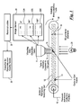
- FIG. 1 a highly schematic view of an optical projection tomography system including a quality score classifier is shown.
- Cells 15 are suspended in an index of refraction matching gel 12 contained in a capillary tube 18.
- Pressure 10 is applied to the gel 12 to move the cells into the optical path of a high-magnification microscope including an objective lens 5.
- the objective lens 5 is scanned or vibrated by, for example, a (not shown) piezo-electric element.
- the capillary tube 18 is positioned to be scanned by the vibrating objective lens 5.
- An illumination source 20 operates to illuminate objects, such as biological cells passing through the field of view of the objective lens 5.
- An image sensor 25 is located to acquire images transmitted from the objective lens 5.
- a plurality of pseudo-projection images here exemplified by pseudo-projection images 22A, 22B and 22C are acquired by the image sensor 25 at varying angles of view as presented by the rotating capillary tube 18.
- the plurality of pseudo-projection images are then passed to a reconstruction processor 35 for producing 3D images.
- a quality score classifier 36 is coupled to the reconstruction processor 35 to receive the reconstructed 3D images.
- the quality score classifier in one embodiment, then classifies the received images as acceptable or of poor quality and not acceptable for further analysis.
- the plurality of pseudo-projection images here exemplified by pseudo-projection images 22A, 22B and 22C are shown acquired at angles of 0°, 90° and 180° respectively. It will be understood that these are merely examples and that the number of pseudo-projection images actually acquired will typically be several hundred images.
- the reconstruction processor 35 may be of the type as described in Fauver et al. referenced hereinabove.
- the quality score classifier may, for example, advantageously assign numerical scores to the reconstructed 3D images where the numerical scores have values scaled to represent degrees of quality of the images. In other embodiments the quality score classifier may simply sort poor quality images from other images.
- an example of operation may include the following functions.
- good quality classification depends on good quality 3D reconstructions in step 6. Issues governing quality arise from detrimental effects that may be introduced by the operation of a given optical tomography system and characteristics relating to deficient correction of random cell motion occurring during image capture. If cells are not properly in focus in the set of pseudo-projections or if the cell moves off the camera frame during capture, the resulting reconstruction will not be ideal. In a likewise fashion, if proper corrections for the random motions arising during image capture are not made, then the various features of the cell will not reinforce each other in the reconstruction, thus compromising reconstruction quality.
- detection of poor quality reconstructions may be carried out by various methods including poor quality detection based on features describing streaking in reconstruction, poor quality detection based on a comparison between fixed focal plane and reconstructed slice, poor quality detection using parameters of cosine fitting to center of mass trends and the like. It has been observed that streaking may have various causes. Image quality issues due to poor focus and random motions affecting cell alignment have similar streaking effects on reconstructions.
- FIG. 2A and FIG. 2B slices from reconstructions where pseudo-projections are in good focus and poor focus respectively are shown. Now addressing effects of poor focus, it has been observed as shown in FIG. 2B , that occasionally, cells are not well focused across a sub-set of the pseudo-projections. In poorly focused pseudo-projections, morphology is usually blurred, producing blurred image features such as lobe 202. When back-projected, such blurred image features do not ideally align with the same features found in well-focused pseudo-projections from the same set. This lack of alignment creates a streaking effect in the reconstruction.
- FIG. 3A and FIG. 3B slices from reconstructions where pseudo-projections are in good alignment and poor alignment respectively are shown. Poor alignment due to random motions of the cell occurring during image capture must be corrected for post-acquisition in software.
- One such system is described in US Patent Publication No. 20080285827, published November 20, 2008 , for co-pending US Patent Application No. 11/750924 to Meyer et al . entitled, "Method For Image Processing And Reconstruction Of Images For Optical Tomography,"
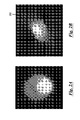
- Figure 3A shows a slice from a reconstruction from a well focused and well aligned cell. Note the crisp boundary 302 describing the cell and nucleus.
- Figure 3B shows a slice from a reconstruction created where a sub-set of the pseudo-projections were well focused but poorly aligned with the other pseudo-projections. Note that cell and nuclear boundaries are not crisp and that a streak artifact is observed in the background of the reconstruction.
- segmentation development may be initiated with annotations of reconstructions made by hand drawn cell boundaries. These boundaries serve as a reference to guide development.
- the resulting segmentation algorithm includes identification of a threshold, selected for the particular cell under examination.
- threshold selection follows a procedure wherein a cell segmentation program first selects fifteen slices near the center of the reconstruction. With each slice a range of thresholds is applied and an area derivative and a second derivative is computed for each. To select a threshold for each slice, a negative second derivative is located at a threshold higher than the maximum area derivative. A global threshold is chosen using a percentile of the selected slice thresholds. Finally, the largest object is kept, and any holes in it are filled using digital techniques.
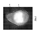
- FIG. 4 a slice from a reconstructed cell where the cell boundary and corresponding segmentation boundary are shown.
- a computed segmentation mask was developed to correspond to this boundary.
- the resulting segmentation algorithm produced the boundary 402.
- the segmentation mask was applied to the reconstruction by setting all voxel values in the reconstruction that are also within the segmentation mask to a value of 255.
- voxel and pixel light intensity values for reconstructions and image slices typically vary in brightness on a scale from 0 to 255, but that other scales may also be employed without departing from the scope of the invention.
- the pseudo projections include a cell 100, where the cell has been segmented and the background voxels have been amplified to fill the grey scale range.
- Figure 5A and FIG. 5B respectively show the result of further processing of the images of FIG. 3A and FIG. 3B after a mask has been applied and the background has been equalized so that the histogram for the background extends across the available grey scale range.
- the streak artifact 102 may be characterized by computing a set of features on those voxels in the reconstruction that are associated with the background of the reconstruction.
- Table 1 provides a list of features that may advantageously be employed for characterizing the streak effect.
- TABLE I Feature Type Description Histogram As seen in FIG. 5A and Fig. 5B , there is a greater variance in background voxels for the poorly aligned cell 102 versus the well aligned cell 100. Therefore, features that characterize various statistics on background voxels may be employed for detection of poor quality of reconstructions. Such statistics may advantageously include: mode, mean, median, variance, coefficient of variance, skewness, kurtosis, various percentiles of the histogram - 10th, 40th percentile, etc. Spatial Frequency As seen by comparing FIG. 5A and Fig.
- Texture Texture Features characterize the distribution of grey scale values in the background. Texture methods are based on mathematical morphology. Two methods may be especially important for quality detection. First, run length features characterize the length of a gray scale run. These are typically represented in a histogram.
- Run-length features are statistical moments computed on the run-length histogram, such as mean, variance, mode, etc.
- Second, blur residue features characterize texture by computing a difference image using morphological opening or closing on the background and subtracting it from the original, masked image.
- Statistically-based features may be then computed on the background voxels in the difference image for different choices of structure element used for opening and/or closing.
- FIG. 6A and FIG. 6B fixed focal plane and reconstruction slices for a good quality reconstruction are shown respectively.
- Figure 6A shows a fixed focal plane image
- FIG. 6B shows a slice from the reconstruction that best matches it from a good quality reconstruction.
- Figure 7A shows a fixed focal plane image
- FIG. 7B shows a slice from the reconstruction that best matches it from a poor quality reconstruction.
- Another useful method for detection of poor quality images employs parameters of cosine fitting to center of mass trends.
- data collection on an optical tomography system proceeds by moving objects, for example, cells, into position under the objective lens and spinning the capillary tube to collect the set of pseudo-projections.
- the center of mass of the cell moves up and down in a cosine pattern when plotted against capillary angle of rotation.
- Poor registration occurs when the grey-scale mass is not conserved across all pseudo-projections.
- the trend in the center of mass often deviates from a cosine.
- Detection of poor quality reconstruction may therefore be potentially accomplished by fitting the trend in center of mass with a cosine function and characterizing the error of the fit.
- Specific features used for detection include the absolute and radius normalized maximum deviation, and root mean square error (RMSE) between center of mass cosine fit and trend.
- RMSE root mean square error
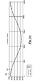
- FIG. 8A an example of a comparison of center of mass trend 802 with fit using a cosine 804 for a good quality reconstruction is shown.
- FIG. 8B shows an example of a comparison of center of mass trend 806 with fit using a cosine 808 for a poor quality reconstruction.
- the horizontal axes represent the pseudo-projection number.
- the vertical axes represent the center of mass position in microns. Note the negligible deviation between fit 802 with trend 804 for the good reconstruction to the point that the curves essentially coincide, and the more substantial fit-trend deviation between lines 806 and 808 for the poor reconstruction.
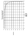
- a quality classifier ROC curve is shown.
- a classifier was created whose output optimally corresponds to the expert identification. This correspondence may be summarized using a receiver operator characteristic (ROC) curve.
- Sensitivity is represented on the vertical axis ranging from 0.0 to 1.0.
- sensitivity measures the detection accuracy for poor reconstructions.
- Specificity is represented on the horizontal axis also ranging from 0.0 to 1.0.
Landscapes
- Engineering & Computer Science (AREA)
- Physics & Mathematics (AREA)
- General Physics & Mathematics (AREA)
- Theoretical Computer Science (AREA)
- Biomedical Technology (AREA)
- Life Sciences & Earth Sciences (AREA)
- Health & Medical Sciences (AREA)
- General Health & Medical Sciences (AREA)
- Molecular Biology (AREA)
- Multimedia (AREA)
- Quality & Reliability (AREA)
- Computer Vision & Pattern Recognition (AREA)
- Investigating Or Analysing Materials By Optical Means (AREA)
- Apparatus For Radiation Diagnosis (AREA)
- Image Processing (AREA)
Description
- The present invention relates generally to analysis of medical imaging data, and, more particularly, to detecting poor quality in three-dimensional (3D) reconstructions in a biological cell imager.
- 3D tomographic reconstructions require projection images as input. A projection image assumes that an object of interest is translucent to a source of exposure such as a light source transmitted through the object of interest. The projection image, then, comprises an integration of the absorption by the object along a ray from the source to the plane of projection. Light in the visible spectrum is used as a source of exposure in optical projection tomography.
- In the case of producing projections from biological cells, the cells are typically stained with hematoxyln, an absorptive stain that attaches to proteins found in cell chromosomes. Cell nuclei are approximately 15 microns in diameter, and in order to promote reconstructions of sub-cellular features it is necessary to maintain sub-micron resolution. For sub-micron resolution, the wavelength of the illuminating source is in the same spatial range as the biological objects of interest. This can result in undesirable refraction effects. As a result a standard projection image cannot be formed. To avoid these undesirable effects, as noted above, the camera aperture is kept open while the plane of focus is swept through the cell. This approach to imaging results in equal sampling of the entire cellular volume, resulting in a pseudo-projection image. A good example of an optical tomography system has been published as United States Patent Application Publication 2004-0076319, on April 22, 2004, corresponding to pending
US Patent Application No. 10/716,744, filed November 18, 2003 - An optical tomography system may advantageously employ scores for classifying objects of interest, for example, to detect lung cancer in its pre-invasive and treatable stage. In order to do so with accuracy and reliability, the classification scores must be based on good quality 3D reconstruction images of the objects being classified. One example of an optical tomography system is being built by VisionGate, Inc. of Gig Harbor Washington, assignee of this application, under the trademark "Cell-CT™." In one aspect, the Cell-CT™ optical tomography system employs scores, designed to provide an indication of lung cancer in its pre-invasive and treatable stage.
- While it is generally understood that poor quality 3D reconstructions may adversely affect classification results in optical tomography systems, an automated system for detecting such poor quality 3D reconstructions has been lacking until now. The system and method disclosed herein provides, for the first time, a solution for detection of poor quality 3D reconstructions useful for an optical tomography system, for example.
-
US 2006/0023219 A1 discloses a shadowgram optical tomography system for imaging an object of interest. The shadowgram optical tomography system includes a parallel ray light source for illuminating the object of interest with a plurality of parallel radiation beams, an object containing tube, where the object of interest is held within the object containing tube such that it is illuminated by the plurality of parallel radiation beams to produce emerging radiation from the object containing tube, a detector array located to receive the emerging radiation, and a system and method for tracking an image of the object of interest. Three-dimensional reconstructions are produced by image processing a plurality of two-dimensional projection images. Also described is a metric for assessing the overall severity of focus error. - The invention provides a system and method for detecting poor quality images in an optical tomography system according to claims 1, 8 and 9.
- More generally described herein is a system and method for detecting poor quality images in an optical tomography system. The system includes an acquisition means for acquiring a set of projection images of an object having a center of mass, where each of the set of projection images is acquired at a different angle of view. A reconstruction means is coupled to receive the projection images, for reconstruction of the projection images into 3D reconstruction images. A quality means for classification of the 3D reconstruction images uses selected features that characterize poor quality reconstructions.
- While the novel features of the invention are set forth with particularity in the appended claims, the invention, both as to organization and content, will be better understood and appreciated, along with other objects and features thereof, from the following detailed description taken in conjunction with the drawings, in which:
-
FIG. 1 shows a highly schematic view of an optical projection tomography system including a quality score classifier. -
FIG. 2A and FIG. 2B show slices from reconstructions where pseudo-projections are in good focus and poor focus respectively. -
FIG. 3A and FIG. 3B show slices from reconstructions where pseudo-projections are in good alignment and poor alignment respectively. -
FIG. 4 shows a slice from a reconstructed cell where the cell boundary and corresponding segmentation boundary are shown. -
FIG. 5A and FIG. 5B show slices from reconstructions where pseudo-projections are in good alignment and poor alignment respectively. -
FIG. 6A and FIG. 6B show a fixed focal plane slice and a reconstruction slice for a good quality reconstruction. -
FIG. 7A and FIG. 7B show a fixed focal plane slice and a reconstruction slice for a poor quality reconstruction. -
FIG. 8A shows a comparison of center of mass trend with a curve fit using a cosine function for a good quality reconstruction. -
FIG. 8B shows a comparison of center of mass trend with a curve fit using a cosine function for a poor quality reconstruction. -
FIG. 9 shows quality classifier ROC curve where sensitivity measures the detection accuracy for poor reconstructions. - The following disclosure describes several embodiments and systems for imaging an object of interest. Several features of methods and systems in accordance with example embodiments of the invention are set forth and described in the figures. It will be appreciated that methods and systems in accordance with other example embodiments of the invention can include additional procedures or features different than those shown in figures.
- Example embodiments are described herein with respect to biological cells. However, it will be understood that these examples are for the purpose of illustrating the principles of the invention, and that the invention is not so limited. Additionally, methods and systems in accordance with several example embodiments of the invention may not include all of the features shown in these figures. Throughout the figures, like reference numbers refer to similar or identical components or procedures.
- Unless the context requires otherwise, throughout the specification and claims which follow, the word "comprise" and variations thereof, such as, "comprises" and "comprising" are to be construed in an open, inclusive sense that is as "including, but not limited to."
- Reference throughout this specification to "one example" or "an example embodiment," "one embodiment," "an embodiment" or various combinations of these terms means that a particular feature, structure or characteristic described in connection with the embodiment is included in at least one embodiment of the present disclosure. Thus, the appearances of the phrases "in one embodiment" or "in an embodiment" in various places throughout this specification are not necessarily all referring to the same embodiment. Furthermore, the particular features, structures, or characteristics may be combined in any suitable manner in one or more embodiments.
- Generally as used herein the following terms have the following meanings when used within the context of optical tomography processes:
- "Capillary tube" has its generally accepted meaning and is intended to include transparent microcapillary tubes and equivalent items with an inside diameter generally of 500 microns or less.
- "Depth of field" is the length along the optical axis within which the focal plane may be shifted before an unacceptable image blur for a specified feature is produced.
- "Object" means an individual cell, item, thing, particle or other microscopic entity.
- "Pseudo-projection" or "pseudo-projection image" includes a single image representing a sampled volume of extent larger than the native depth of field of a given set of optics. One concept of a pseudo-projection is taught in Fauver '744.
- "Specimen" means a complete product obtained from a single test or procedure from an individual patient (e.g., sputum submitted for analysis, a biopsy, or a nasal swab). A specimen may be composed of one or more objects. The result of the specimen diagnosis becomes part of the case diagnosis.
- "Sample" means a finished cellular preparation that is ready for analysis, including all or part of an aliquot or specimen.
- As used in this specification, the terms "processor" and "computer processor" encompass a personal computer, a microcontroller, a microprocessor, a field programmable object array (FPOA), a digital signal processor (DSP), an application-specific integrated circuit (ASIC), a field programmable gate array (FPGA), a programmable logic array (PLA), or any other digital processing engine, device or equivalent including related memory devices, transmission devices, pointing devices, input/output devices, displays and equivalents.
- Referring now to
FIG. 1 a highly schematic view of an optical projection tomography system including a quality score classifier is shown.Cells 15 are suspended in an index ofrefraction matching gel 12 contained in acapillary tube 18.Pressure 10 is applied to thegel 12 to move the cells into the optical path of a high-magnification microscope including anobjective lens 5. Theobjective lens 5 is scanned or vibrated by, for example, a (not shown) piezo-electric element. Thecapillary tube 18 is positioned to be scanned by the vibratingobjective lens 5. Anillumination source 20 operates to illuminate objects, such as biological cells passing through the field of view of theobjective lens 5. Animage sensor 25 is located to acquire images transmitted from theobjective lens 5. A plurality of pseudo-projection images, here exemplified bypseudo-projection images image sensor 25 at varying angles of view as presented by the rotatingcapillary tube 18. The plurality of pseudo-projection images are then passed to areconstruction processor 35 for producing 3D images. Aquality score classifier 36 is coupled to thereconstruction processor 35 to receive the reconstructed 3D images. The quality score classifier, in one embodiment, then classifies the received images as acceptable or of poor quality and not acceptable for further analysis. - In the example, the plurality of pseudo-projection images, here exemplified by
pseudo-projection images reconstruction processor 35 may be of the type as described in Fauver et al. referenced hereinabove. The quality score classifier may, for example, advantageously assign numerical scores to the reconstructed 3D images where the numerical scores have values scaled to represent degrees of quality of the images. In other embodiments the quality score classifier may simply sort poor quality images from other images. - Having described the major components of an optical tomography system including a quality score classifier, it is now considered useful to an understanding of the invention to describe an example embodiment of operation of such a system. Taken in a substantially chronological order, an example of operation may include the following functions.
- 1. A specimen for examination is processed to remove non-diagnostic elements and is fixed and stained.
- 2. The specimen is then suspended in a gel medium. The cells in gel mixture are then inserted into a
glass micro-capillary tube 18 of approximately 50µinner diameter 16. - 3. Pressure is applied to the gel to move the cells into the
optical path 14 of a high-magnification microscope. - 4. Once the cells are in place the tube is rotated to permit capture of 500 high resolution images of the desired object taken over 360 degrees of tube rotation. These images are simulations of projection images created by integrating the light from the objective lens as the objective scans the nucleus. The simulated projection or pseudo-projection images thus represent the entire nuclear content in a single image, taken from a single perspective.
- 5. Pseudo-projection images are processed to correct for residual noise and motion artifacts.
- 6. The corrected pseudo projections are processed using filtered back projection to yield a 3D tomographic representation of the cell.
- 7. Based on the tomographic reconstruction, features are computed that are used, for example, to detect cells with characteristics of indicative of cancer and its precursors. These features may be used in a classifier whose output designates the likelihood that object under investigation belongs in a specified class, such as a cancer cell.
- Among other things, good quality classification depends on good quality 3D reconstructions in step 6. Issues governing quality arise from detrimental effects that may be introduced by the operation of a given optical tomography system and characteristics relating to deficient correction of random cell motion occurring during image capture. If cells are not properly in focus in the set of pseudo-projections or if the cell moves off the camera frame during capture, the resulting reconstruction will not be ideal. In a likewise fashion, if proper corrections for the random motions arising during image capture are not made, then the various features of the cell will not reinforce each other in the reconstruction, thus compromising reconstruction quality.
- Poor quality images may result in distorted reconstructions entering the classification stream, producing unpredictable results reflected in incorrect or distorted classification scoring. Therefore, poor quality reconstructions need to be detected to ensure the integrity of classification. A method for detecting poor quality reconstructions in cases where, for example, pseudo-projection images were not collected in an ideal way, when registration was not successful, or for other reasons affecting image quality, is described in detail herein sufficient for one skilled in the art to make and use the invention.
- As described further herein, detection of poor quality reconstructions may be carried out by various methods including poor quality detection based on features describing streaking in reconstruction, poor quality detection based on a comparison between fixed focal plane and reconstructed slice, poor quality detection using parameters of cosine fitting to center of mass trends and the like. It has been observed that streaking may have various causes. Image quality issues due to poor focus and random motions affecting cell alignment have similar streaking effects on reconstructions.
- Referring now to
FIG. 2A and FIG. 2B , slices from reconstructions where pseudo-projections are in good focus and poor focus respectively are shown. Now addressing effects of poor focus, it has been observed as shown inFIG. 2B , that occasionally, cells are not well focused across a sub-set of the pseudo-projections. In poorly focused pseudo-projections, morphology is usually blurred, producing blurred image features such aslobe 202. When back-projected, such blurred image features do not ideally align with the same features found in well-focused pseudo-projections from the same set. This lack of alignment creates a streaking effect in the reconstruction. - Referring now to
FIG. 3A and FIG. 3B , slices from reconstructions where pseudo-projections are in good alignment and poor alignment respectively are shown. Poor alignment due to random motions of the cell occurring during image capture must be corrected for post-acquisition in software. One such system is described inUS Patent Publication No. 20080285827, published November 20, 2008 , for co-pendingUS Patent Application No. 11/750924 to Meyer et al - In some circumstances, the correction algorithm does not converge to an appropriate solution and poor alignment is observed in the acquired set of corrected pseudo-projections that are used as input to the filtered-backprojection algorithm. As a result, cell morphology does not reinforce in the backprojection. The effect of poor alignment is similar to that of poor focus. Lack of good quality alignment produces streaking in the reconstruction.
Figure 3A shows a slice from a reconstruction from a well focused and well aligned cell. Note thecrisp boundary 302 describing the cell and nucleus.Figure 3B shows a slice from a reconstruction created where a sub-set of the pseudo-projections were well focused but poorly aligned with the other pseudo-projections. Note that cell and nuclear boundaries are not crisp and that a streak artifact is observed in the background of the reconstruction. - Comparing
Fig. 2B andFIG. 3B , it can be observed that poor focus and poor registration produce similar effects on the reconstruction. These effects may be recognized in order to detect a poor quality reconstruction by characterizing the voxels in the reconstruction that are not associated with the cell. Performing the recognition based on the background allows for an algorithm that is not as strongly influenced by the diverse biology that one observes from cell to cell. The process begins with a segmentation algorithm to separate the cell from the background. - For some applications, segmentation development may be initiated with annotations of reconstructions made by hand drawn cell boundaries. These boundaries serve as a reference to guide development. The resulting segmentation algorithm includes identification of a threshold, selected for the particular cell under examination. In one example, threshold selection follows a procedure wherein a cell segmentation program first selects fifteen slices near the center of the reconstruction. With each slice a range of thresholds is applied and an area derivative and a second derivative is computed for each. To select a threshold for each slice, a negative second derivative is located at a threshold higher than the maximum area derivative. A global threshold is chosen using a percentile of the selected slice thresholds. Finally, the largest object is kept, and any holes in it are filled using digital techniques.
- Referring now to
FIG. 4 , a slice from a reconstructed cell where the cell boundary and corresponding segmentation boundary are shown. Using the segmentation techniques described herein a computed segmentation mask was developed to correspond to this boundary. The resulting segmentation algorithm produced theboundary 402. The segmentation mask was applied to the reconstruction by setting all voxel values in the reconstruction that are also within the segmentation mask to a value of 255. Those skilled in the art will recognize that voxel and pixel light intensity values for reconstructions and image slices typically vary in brightness on a scale from 0 to 255, but that other scales may also be employed without departing from the scope of the invention. - Referring now to
FIG. 5A and FIG. 5B , slices from reconstructions where pseudo-projections are in good alignment and poor alignment respectively are shown. The pseudo projections include acell 100, where the cell has been segmented and the background voxels have been amplified to fill the grey scale range.Figure 5A and FIG. 5B respectively show the result of further processing of the images ofFIG. 3A and FIG. 3B after a mask has been applied and the background has been equalized so that the histogram for the background extends across the available grey scale range. Note theprominent streak artifact 102 for the image associated with poor registration. Thestreak artifact 102 may be characterized by computing a set of features on those voxels in the reconstruction that are associated with the background of the reconstruction. Table 1 provides a list of features that may advantageously be employed for characterizing the streak effect.TABLE I Feature Type Description Histogram As seen in FIG. 5A and Fig. 5B , there is a greater variance in background voxels for the poorly alignedcell 102 versus the wellaligned cell 100. Therefore, features that characterize various statistics on background voxels may be employed for detection of poor quality of reconstructions. Such statistics may advantageously include: mode, mean, median, variance, coefficient of variance, skewness, kurtosis, various percentiles of the histogram - 10th, 40th percentile, etc.Spatial Frequency As seen by comparing FIG. 5A and Fig. 5B , the images exhibit a different pattern in the spatial frequencies of the two different reconstructed slices. Therefore, procedures whose values characterize the spatial frequencies of the reconstructed slices may be employed for detection of poor quality of reconstructions. Useful procedures may advantageously include Fourier transforms, FFT, wavelet transform, etc.Texture Texture Features characterize the distribution of grey scale values in the background. Texture methods are based on mathematical morphology. Two methods may be especially important for quality detection. First, run length features characterize the length of a gray scale run. These are typically represented in a histogram. Run-length features are statistical moments computed on the run-length histogram, such as mean, variance, mode, etc., Second, blur residue features characterize texture by computing a difference image using morphological opening or closing on the background and subtracting it from the original, masked image. Statistically-based features may be then computed on the background voxels in the difference image for different choices of structure element used for opening and/or closing. - Another technique for assessing reconstruction quality is to compare reconstruction slices with their corresponding fixed focal plane slices. So long as they are well focused, fixed focal plane slices should be free of whatever distortions were introduced into the reconstruction during image capture or processing. Therefore, these images form an excellent reference to judge reconstruction quality. Referring now to
FIG. 6A and FIG. 6B , fixed focal plane and reconstruction slices for a good quality reconstruction are shown respectively.Figure 6A shows a fixed focal plane image andFIG. 6B shows a slice from the reconstruction that best matches it from a good quality reconstruction. Similarly,Figure 7A shows a fixed focal plane image andFIG. 7B shows a slice from the reconstruction that best matches it from a poor quality reconstruction. - Features derived to judge good quality of reconstruction are formed by creating a difference image between the fixed focus and reconstruction slice images. In contrast with the above features of Table 1, difference image features are computed for those voxels that are associated with the cell. Low average difference for the portion of the images containing the cell reflects good quality of reconstruction.
- Another useful method for detection of poor quality images employs parameters of cosine fitting to center of mass trends. As indicated by
FIG. 1 , data collection on an optical tomography system proceeds by moving objects, for example, cells, into position under the objective lens and spinning the capillary tube to collect the set of pseudo-projections. When viewed from a specific perspective the center of mass of the cell moves up and down in a cosine pattern when plotted against capillary angle of rotation. Poor registration occurs when the grey-scale mass is not conserved across all pseudo-projections. When this occurs, the trend in the center of mass often deviates from a cosine. Detection of poor quality reconstruction may therefore be potentially accomplished by fitting the trend in center of mass with a cosine function and characterizing the error of the fit. Specific features used for detection include the absolute and radius normalized maximum deviation, and root mean square error (RMSE) between center of mass cosine fit and trend. - Referring now to
FIG. 8A , an example of a comparison of center ofmass trend 802 with fit using acosine 804 for a good quality reconstruction is shown.FIG. 8B shows an example of a comparison of center ofmass trend 806 with fit using acosine 808 for a poor quality reconstruction. In both graphs the horizontal axes represent the pseudo-projection number. The vertical axes represent the center of mass position in microns. Note the negligible deviation betweenfit 802 withtrend 804 for the good reconstruction to the point that the curves essentially coincide, and the more substantial fit-trend deviation betweenlines - With respect to the example of
FIG. 8A the following curve fit statistics apply: - Fit error mean = 0.102 µm,
- Fit error standard deviation = 0.071 µm,
- Fit error maximum (absolute) = 0.28 µm,
- Fit error maximum delta = 0.08 µm,
- Radius to object center = 19.797 µm,
- X offset = -0.222 µm,
- Phase =0.114 degrees,
- Relative Deviation in frequency = 0.147%, and
- Linear drift in X = 0 µm.
- With respect to the example of
FIG. 8B the following curve fit statistics apply: - Fit error mean = 1.051 µm,
- Fit error standard deviation = 0.756 µm,
- Fit error maximum (absolute) = 2.35µm,
- Fit error maximum delta = 4.541 µm,
- Radius to object center = 8.993 µm,
- X offset = -0.14 µm,
- Phase = -19.033 degrees,
- Relative deviation in frequency = 0.356%, and
- Linear drift in X = 0.005 µm.
- Referring now to
FIG. 9 , a quality classifier ROC curve is shown. Using the above described features and expert identification of poor reconstruction quality, a classifier was created whose output optimally corresponds to the expert identification. This correspondence may be summarized using a receiver operator characteristic (ROC) curve. Sensitivity is represented on the vertical axis ranging from 0.0 to 1.0. Here sensitivity measures the detection accuracy for poor reconstructions. Specificity is represented on the horizontal axis also ranging from 0.0 to 1.0. Those skilled in the art having the full benefit of this disclosure will understand how to build a quality scoring classifier using the selected features identified hereinabove. - While specific embodiments of the invention have been illustrated and described herein, it is realized that numerous modifications and changes will occur to those skilled in the art. It is therefore to be understood that the appended claims are intended to cover all such modifications and changes as fall within the scope of the invention.
Claims (13)
- A system for detecting poor quality images in an optical tomography system comprising:acquisition means (25) for acquiring a set of pseudo-projection images (22) of an object (15) comprising a biological cell and having a center of mass, where each of the set of pseudo-projection images (22) is acquired at a different angle of view;reconstruction means (35), coupled to receive the pseudo-projection images (22), for reconstruction of the pseudo-projection images (22) into 3D reconstruction images; andquality means (36) for classification of the 3D reconstruction images using selected features that characterize poor quality reconstructions;wherein the selected features include difference image features that are formed by creating a difference image between a fixed focus image and a reconstruction slice image; andwherein the difference image features are computed for those voxels that are associated with the cell (100) including an average difference for the portion of the images containing the cell (100).
- The system of claim 1 or the method of claim 8 wherein the selected features describe streaking (102) in the 3D reconstruction images.
- The system or method of claim 2 wherein the set of pseudo-projection images (22) present a center of mass trend (806) for the object (15) and the selected features further include comparison features calculated from a comparison of the center of mass trend (806) with a cosine fit curve (808).
- The system of claim 1 or the method of claim 8 wherein the set of pseudo-projection images (22) present a center of mass trend (806) for the object (15) and the selected features are calculated from a comparison of the center of mass trend (806) with a cosine function fitting the trend (806) in the center of mass.
- The system or method of claim 4 wherein the calculation of the selected features includes measuring an error between the cosine function and the center of mass trend (806).
- The system or method of claim 5 wherein the selected features include the absolute and radius normalized maximum deviation, and root mean square error (RMSE) between the cosine function and the center of mass trend (806).
- The system of claim 1 or the method of claim 8 wherein the selected features are selected from the group consisting of histogram statistics, texture features and spatial frequency features.
- A method for detecting poor quality images in an optical tomography system comprising:operating the optical tomography system to acquire a set of pseudo-projection images (22) of an object (15) comprising a biological cell and having a center of mass, where each of the set of pseudo-projection images (22) is acquired at a different angle of view;transmitting the set of pseudo-projection images (22) to a processor for reconstructing the pseudo-projection images (22) into 3D reconstruction images; andoperating the processor to classify the 3D reconstruction images using selected features that characterize poor quality reconstructions;wherein the selected features include difference image features that are formed by creating a difference image between a fixed focus image and a reconstruction slice image; andwherein the difference image features are computed for those voxels that are associated with the cell (100) including an average difference for the portion of the images containing the cell (100).
- A system for detecting poor quality images in an optical tomography system where a set of cells are suspended in an index of refraction matching gel (12) contained in a rotating capillary tube (18), where pressure is applied to the gel (12) to move the cells into the optical path of a microscope including an objective lens (5) that is scanned through the capillary tube (18) while an illumination source operates to illuminate cells passing through the field of view of the objective lens (5) and where the optical tomography system includes an image sensor located to acquire pseudo-projection images (22) transmitted from the objective lens (5), where each of the set of pseudo-projection images (22) is acquired at a different angle of view, the system comprising:a reconstruction processor (35), coupled to receive a set of pseudo-projection images (22) of each of the set of cells, each cell (100) having a center of mass, where the reconstruction processor (35) creates at least one 3D reconstruction image;a quality score classifier coupled to receive the at least one 3D reconstruction image, where the quality score classifier scores selected features in the at least one 3D reconstruction image;wherein the selected features describe streaking (102) in reconstruction;wherein the set of pseudo-projection images (22) present a center of mass trend (806) for the cell (100) and the selected features further include comparison features calculated from a comparison of the center of mass trend (806) with a cosine fit curve (808);wherein the selected features include difference image features that are formed by creating a difference image between a fixed focus image and a reconstruction slice images; andwherein the difference image features are computed for voxels that are associated with the cell (100) including an average difference for the portion of the images containing the cell (100).
- The system of claim 9 wherein the calculation of the selected features includes selected features includes measuring an error between the cosine function and the center of mass trend (806).
- The system of claim 10 wherein the selected features include the absolute and radius normalized maximum deviation, and root mean square error (RMSE) between the cosine function and the center of mass trend (806).
- The system of claim 9 wherein the selected features are selected from the group consisting of histogram statistics, texture features and spatial frequency features.
- The system of claim 1 or the method of claim 8 wherein the object (15) comprises a biological cell (100).
Applications Claiming Priority (2)
| Application Number | Priority Date | Filing Date | Title |
|---|---|---|---|
| US12/470,413 US8155420B2 (en) | 2009-05-21 | 2009-05-21 | System and method for detecting poor quality in 3D reconstructions |
| PCT/US2010/035673 WO2010135592A2 (en) | 2009-05-21 | 2010-05-20 | System and method for detecting poor quality in 3d reconstructions |
Publications (3)
| Publication Number | Publication Date |
|---|---|
| EP2432389A2 EP2432389A2 (en) | 2012-03-28 |
| EP2432389A4 EP2432389A4 (en) | 2013-07-03 |
| EP2432389B1 true EP2432389B1 (en) | 2015-07-08 |
Family
ID=43124586
Family Applications (1)
| Application Number | Title | Priority Date | Filing Date |
|---|---|---|---|
| EP10778428.2A Not-in-force EP2432389B1 (en) | 2009-05-21 | 2010-05-20 | System and method for detecting poor quality in 3d reconstructions |
Country Status (8)
| Country | Link |
|---|---|
| US (1) | US8155420B2 (en) |
| EP (1) | EP2432389B1 (en) |
| JP (1) | JP5584289B2 (en) |
| CN (1) | CN102481117B (en) |
| AU (1) | AU2010249504B2 (en) |
| CA (1) | CA2762848C (en) |
| ES (1) | ES2544885T3 (en) |
| WO (1) | WO2010135592A2 (en) |
Families Citing this family (19)
| Publication number | Priority date | Publication date | Assignee | Title |
|---|---|---|---|---|
| US8718743B2 (en) * | 2008-04-24 | 2014-05-06 | Duke University | Methods for single-pass volumetric bidirectional blood flow imaging spectral domain optical coherence tomography using a modified hilbert transform |
| WO2009155151A2 (en) * | 2008-06-20 | 2009-12-23 | Visiongate, Inc. | Functional imaging of cells optical projection tomography |
| US8693745B2 (en) * | 2009-05-04 | 2014-04-08 | Duke University | Methods and computer program products for quantitative three-dimensional image correction and clinical parameter computation in optical coherence tomography |
| US9279659B2 (en) | 2011-01-21 | 2016-03-08 | Duke University | Systems and methods for complex conjugate artifact resolved optical coherence tomography |
| US10766245B2 (en) * | 2014-08-19 | 2020-09-08 | Materialise N.V. | Slice area distribution for obtaining improved performance in additive manufacturing techniques |
| US9594072B2 (en) * | 2015-06-30 | 2017-03-14 | Visiongate, Inc. | System and method for determining cell adequacy in a cytological analysis system |
| ES2987312T3 (en) | 2015-12-30 | 2024-11-14 | Visiongate Inc | System and procedure for automated detection and monitoring of dysplasia |
| US11069054B2 (en) | 2015-12-30 | 2021-07-20 | Visiongate, Inc. | System and method for automated detection and monitoring of dysplasia and administration of immunotherapy and chemotherapy |
| EP3413033B1 (en) | 2017-06-09 | 2020-09-23 | Roche Diagnostics GmbH | Method and apparatus for determining properties of a laboratory sample contained in a laboratory sample container |
| US10753857B2 (en) | 2017-07-24 | 2020-08-25 | Visiongate Inc. | Apparatus and method for measuring microscopic object velocities in flow |
| US12516380B2 (en) | 2018-01-05 | 2026-01-06 | Visiongate, Inc. | Morphometric genotyping of cells using optical tomography for detecting tumor mutational burden |
| WO2019169157A1 (en) | 2018-02-28 | 2019-09-06 | Visiongate, Inc. | Morphometric detection of malignancy associated change |
| US12612663B2 (en) | 2018-06-06 | 2026-04-28 | Visiongate, Inc. | Morphometric detection of DNA mismatch repair deficiency |
| US11428692B2 (en) | 2018-07-11 | 2022-08-30 | Visiongate, Inc. | Specimen enrichment for optical tomography cell analysis |
| JP7270907B2 (en) * | 2019-02-27 | 2023-05-11 | 国立大学法人浜松医科大学 | Cell observation system and cell observation method |
| CN110554054B (en) * | 2019-09-05 | 2021-10-29 | 西安多维机器视觉检测技术有限公司 | Three-dimensional blade breakage detection system of mechanically-clamped indexable turning tool |
| CN112770105B (en) * | 2020-12-07 | 2022-06-03 | 宁波大学 | Repositioning stereo image quality evaluation method based on structural features |
| JP2023005078A (en) * | 2021-06-28 | 2023-01-18 | 株式会社リガク | Angle error estimation device, method, and program |
| AU2023317489A1 (en) | 2022-08-02 | 2025-02-20 | Visiongate, Inc. | Ai-based cell classification method and system |
Family Cites Families (81)
| Publication number | Priority date | Publication date | Assignee | Title |
|---|---|---|---|---|
| US3705771A (en) | 1970-01-14 | 1972-12-12 | Bio Physics Systems Inc | Photoanalysis apparatus |
| US3657537A (en) | 1970-04-03 | 1972-04-18 | Bausch & Lomb | Computerized slit-scan cyto-fluorometer for automated cell recognition |
| US3748468A (en) | 1971-12-22 | 1973-07-24 | Gen Electric | Automatic electron microscope field counter |
| US3999047A (en) | 1972-09-05 | 1976-12-21 | Green James E | Method and apparatus utilizing color algebra for analyzing scene regions |
| US4175860A (en) | 1977-05-31 | 1979-11-27 | Rush-Presbyterian-St. Luke's Medical Center | Dual resolution method and apparatus for use in automated classification of pap smear and other samples |
| US4360885A (en) | 1980-01-02 | 1982-11-23 | Edgar Albert D | Micro-optical tomography |
| US4873653A (en) | 1986-04-09 | 1989-10-10 | Carl-Zeiss-Stiftung | Microscope system for providing three-dimensional resolution |
| US4786165A (en) | 1986-07-10 | 1988-11-22 | Toa Medical Electronics Co., Ltd. | Flow cytometry and apparatus therefor |
| US4858128A (en) | 1986-08-11 | 1989-08-15 | General Electric Company | View-to-view image correction for object motion |
| DE3905619C2 (en) | 1988-02-23 | 2000-04-13 | Olympus Optical Co | Image input / output device |
| GB2239575B (en) | 1989-10-17 | 1994-07-27 | Mitsubishi Electric Corp | Motion vector detecting apparatus and image blur correcting apparatus, and video camera including such apparatus |
| US5141609A (en) | 1990-11-16 | 1992-08-25 | The Trustees Of The Leland Stanford Junior University | Method and device employing time-delayed integration for detecting sample components after separation |
| JP3084295B2 (en) | 1991-02-27 | 2000-09-04 | シスメックス株式会社 | Flow image cytometer |
| JP3327948B2 (en) | 1992-06-09 | 2002-09-24 | オリンパス光学工業株式会社 | Optical image reconstruction device |
| US6026174A (en) | 1992-10-14 | 2000-02-15 | Accumed International, Inc. | System and method for automatically detecting malignant cells and cells having malignancy-associated changes |
| US5402460A (en) | 1993-08-02 | 1995-03-28 | University Of Washington | Three-dimensional microtomographic analysis system |
| US6215587B1 (en) | 1994-02-14 | 2001-04-10 | Robert R. Alfano | Microscope imaging inside highly scattering media |
| JPH07286953A (en) | 1994-04-19 | 1995-10-31 | Toa Medical Electronics Co Ltd | Imaging flow sight meter |
| AU3629295A (en) | 1994-09-20 | 1996-04-09 | Neopath, Inc. | Apparatus for automated identification of thick cell groupings on a biological specimen |
| US5552605A (en) | 1994-11-18 | 1996-09-03 | Picker International, Inc. | Motion correction based on reprojection data |
| US5539800A (en) | 1995-03-24 | 1996-07-23 | The Regents Of The University Of California, Office Of Technology Transfer | Pseudolocal tomography |
| US5550892A (en) | 1995-03-24 | 1996-08-27 | The Regents Of The University Of California | Enhanced local tomography |
| US6252979B1 (en) | 1995-06-07 | 2001-06-26 | Tripath Imaging, Inc. | Interactive method and apparatus for sorting biological specimens |
| US6165734A (en) | 1995-12-12 | 2000-12-26 | Applied Spectral Imaging Ltd. | In-situ method of analyzing cells |
| GB2309368B (en) | 1996-01-18 | 1999-09-15 | Hamamatsu Photonics Kk | An optical computer tomographic apparatus and image reconstruction method using optical computer tomography |
| US6078681A (en) | 1996-03-18 | 2000-06-20 | Marine Biological Laboratory | Analytical imaging system and process |
| US5915048A (en) | 1996-06-05 | 1999-06-22 | Zetetic Institute | Method and apparatus for discriminating in-focus images from out-of-focus light signals from background and foreground light sources |
| WO1998023207A1 (en) | 1996-11-29 | 1998-06-04 | Imaging Diagnostic Systems, Inc. | Method for reconstructing the image of an object scanned with a laser imaging apparatus |
| US5760901A (en) | 1997-01-28 | 1998-06-02 | Zetetic Institute | Method and apparatus for confocal interference microscopy with background amplitude reduction and compensation |
| US6091983A (en) | 1997-02-07 | 2000-07-18 | Alfano; Robert R. | Imaging of objects in turbid media based upon the preservation of polarized luminescence emitted from contrast agents |
| US5878103A (en) | 1997-06-30 | 1999-03-02 | Siemens Corporate Research, Inc. | Adaptive detector masking for speed-up of cone beam reconstruction |
| US5909476A (en) | 1997-09-22 | 1999-06-01 | University Of Iowa Research Foundation | Iterative process for reconstructing cone-beam tomographic images |
| US6388809B1 (en) | 1997-10-29 | 2002-05-14 | Digital Optical Imaging Corporation | Methods and apparatus for improved depth resolution use of out-of-focus information in microscopy |
| CA2310672A1 (en) | 1997-11-19 | 1999-05-27 | University Of Washington | High throughput optical scanner |
| JPH11218486A (en) * | 1998-01-30 | 1999-08-10 | Seitai Hikarijoho Kenkyusho:Kk | Optical ct method |
| JP4473358B2 (en) * | 1999-01-21 | 2010-06-02 | 株式会社東芝 | Diagnostic equipment |
| US6608682B2 (en) | 1999-01-25 | 2003-08-19 | Amnis Corporation | Imaging and analyzing parameters of small moving objects such as cells |
| US6249341B1 (en) | 1999-01-25 | 2001-06-19 | Amnis Corporation | Imaging and analyzing parameters of small moving objects such as cells |
| US6473176B2 (en) | 1999-01-25 | 2002-10-29 | Amnis Corporation | Imaging and analyzing parameters of small moving objects such as cells |
| US7450229B2 (en) | 1999-01-25 | 2008-11-11 | Amnis Corporation | Methods for analyzing inter-cellular phenomena |
| US6975400B2 (en) | 1999-01-25 | 2005-12-13 | Amnis Corporation | Imaging and analyzing parameters of small moving objects such as cells |
| US7003143B1 (en) | 1999-11-02 | 2006-02-21 | Hewitt Charles W | Tomographic microscope for high resolution imaging and method of analyzing specimens |
| DE10000185A1 (en) * | 2000-01-05 | 2001-07-12 | Philips Corp Intellectual Pty | Method for displaying the time course of the blood flow in an examination object |
| WO2002017219A1 (en) | 2000-08-25 | 2002-02-28 | Amnis Corporation | Measuring the velocity of small moving objects such as cells |
| DE10100572A1 (en) * | 2001-01-09 | 2002-07-11 | Philips Corp Intellectual Pty | Method for displaying blood flow in a vascular tree |
| US6591003B2 (en) | 2001-03-28 | 2003-07-08 | Visiongate, Inc. | Optical tomography of small moving objects using time delay and integration imaging |
| US20060023219A1 (en) | 2001-03-28 | 2006-02-02 | Meyer Michael G | Optical tomography of small objects using parallel ray illumination and post-specimen optical magnification |
| US6522775B2 (en) | 2001-03-28 | 2003-02-18 | Alan C. Nelson | Apparatus and method for imaging small objects in a flow stream using optical tomography |
| US6519355B2 (en) | 2001-03-28 | 2003-02-11 | Alan C. Nelson | Optical projection imaging system and method for automatically detecting cells having nuclear and cytoplasmic densitometric features associated with disease |
| US6944322B2 (en) | 2001-03-28 | 2005-09-13 | Visiongate, Inc. | Optical tomography of small objects using parallel ray illumination and post-specimen optical magnification |
| DE10116682A1 (en) * | 2001-04-04 | 2002-10-10 | Philips Corp Intellectual Pty | Method and device for reconstructing three-dimensional images from cone beam projection data |
| AU2002303396A1 (en) * | 2001-04-20 | 2002-11-05 | Case Western Reserve University | System and method for reducing effects of rotational motion |
| GB0112392D0 (en) | 2001-05-22 | 2001-07-11 | Medical Res Council | Optical imaging appartus and associated specimen support means |
| US7141773B2 (en) | 2001-08-06 | 2006-11-28 | Bioview Ltd. | Image focusing in fluorescent imaging |
| US6741730B2 (en) | 2001-08-10 | 2004-05-25 | Visiongate, Inc. | Method and apparatus for three-dimensional imaging in the fourier domain |
| US6636623B2 (en) | 2001-08-10 | 2003-10-21 | Visiongate, Inc. | Optical projection imaging system and method for automatically detecting cells with molecular marker compartmentalization associated with malignancy and disease |
| US6850587B1 (en) | 2001-10-24 | 2005-02-01 | Analogic Corporation | Reprojection-based three-dimensional image reconstruction |
| US6512807B1 (en) * | 2001-11-21 | 2003-01-28 | Koninklijke Philips Electronics, N.V. | Low signal correction for perfusion measurements |
| US7738945B2 (en) | 2002-04-19 | 2010-06-15 | University Of Washington | Method and apparatus for pseudo-projection formation for optical tomography |
| US7197355B2 (en) | 2002-04-19 | 2007-03-27 | Visiongate, Inc. | Variable-motion optical tomography of small objects |
| US7260253B2 (en) | 2002-04-19 | 2007-08-21 | Visiongate, Inc. | Method for correction of relative object-detector motion between successive views |
| US7811825B2 (en) | 2002-04-19 | 2010-10-12 | University Of Washington | System and method for processing specimens and images for optical tomography |
| US6697508B2 (en) | 2002-05-10 | 2004-02-24 | Visiongate, Inc. | Tomographic reconstruction of small objects using a priori knowledge |
| US6770893B2 (en) | 2002-05-13 | 2004-08-03 | Visiongate, Inc. | Method and apparatus for emission computed tomography using temporal signatures |
| US7274809B2 (en) | 2002-08-29 | 2007-09-25 | Perceptronix Medical, Inc. And British Columbia Cancer Agency | Computerized methods and systems related to the detection of malignancy-associated changes (MAC) to detect cancer |
| US8014063B2 (en) | 2002-08-30 | 2011-09-06 | Medical Research Council | Optical projection tomography |
| WO2004075107A2 (en) | 2003-02-18 | 2004-09-02 | Oklahoma Medical Research Foundation | Extended depth of focus microscopy |
| JP2006524087A (en) * | 2003-04-22 | 2006-10-26 | コーニンクレッカ フィリップス エレクトロニクス エヌ ヴィ | Equipment for angiographic radiography |
| EP1658009B1 (en) * | 2003-08-20 | 2011-10-12 | Philips Intellectual Property & Standards GmbH | Method and device for flow reconstruction |
| JP4965433B2 (en) * | 2004-04-21 | 2012-07-04 | コーニンクレッカ フィリップス エレクトロニクス エヌ ヴィ | Cone beam CT apparatus using truncated projection and pre-acquired 3D CT image |
| US20070258122A1 (en) | 2004-10-06 | 2007-11-08 | Bc Cancer Agency | Computer-Tomography Microscope and Computer-Tomography Image Reconstruction Methods |
| US7224540B2 (en) | 2005-01-31 | 2007-05-29 | Datalogic Scanning, Inc. | Extended depth of field imaging system using chromatic aberration |
| EP1846893B1 (en) * | 2005-02-03 | 2015-09-16 | Koninklijke Philips N.V. | Radial adaptive filter for metal artifact correction |
| DE102005014279A1 (en) | 2005-03-24 | 2006-10-05 | Henkel Kgaa | Scent delivery system |
| EP1704814B1 (en) * | 2005-03-25 | 2008-10-29 | FUJIFILM Corporation | Optical tomography apparatus |
| JP5451072B2 (en) * | 2005-09-13 | 2014-03-26 | コーニンクレッカ フィリップス エヌ ヴェ | Spatial decomposition oximetry |
| WO2007067999A2 (en) | 2005-12-09 | 2007-06-14 | Amnis Corporation | Extended depth of field imaging for high speed object analysis |
| US7569789B2 (en) | 2006-03-16 | 2009-08-04 | Visiongate, Inc. | Cantilevered coaxial flow injector apparatus and method for sorting particles |
| DE102006046733B4 (en) * | 2006-09-29 | 2008-07-31 | Siemens Ag | Method and device for joint display of 2D fluoroscopic images and a static 3D image data set |
| US7835561B2 (en) | 2007-05-18 | 2010-11-16 | Visiongate, Inc. | Method for image processing and reconstruction of images for optical tomography |
| US7787112B2 (en) | 2007-10-22 | 2010-08-31 | Visiongate, Inc. | Depth of field extension for optical tomography |
-
2009
- 2009-05-21 US US12/470,413 patent/US8155420B2/en active Active
-
2010
- 2010-05-20 AU AU2010249504A patent/AU2010249504B2/en not_active Ceased
- 2010-05-20 CA CA2762848A patent/CA2762848C/en not_active Expired - Fee Related
- 2010-05-20 JP JP2012512050A patent/JP5584289B2/en not_active Expired - Fee Related
- 2010-05-20 ES ES10778428.2T patent/ES2544885T3/en active Active
- 2010-05-20 CN CN201080033165.9A patent/CN102481117B/en not_active Expired - Fee Related
- 2010-05-20 EP EP10778428.2A patent/EP2432389B1/en not_active Not-in-force
- 2010-05-20 WO PCT/US2010/035673 patent/WO2010135592A2/en not_active Ceased
Also Published As
| Publication number | Publication date |
|---|---|
| EP2432389A4 (en) | 2013-07-03 |
| US20100296713A1 (en) | 2010-11-25 |
| AU2010249504B2 (en) | 2015-05-14 |
| US8155420B2 (en) | 2012-04-10 |
| WO2010135592A2 (en) | 2010-11-25 |
| AU2010249504A1 (en) | 2012-01-19 |
| HK1163481A1 (en) | 2012-09-14 |
| EP2432389A2 (en) | 2012-03-28 |
| JP5584289B2 (en) | 2014-09-03 |
| CN102481117A (en) | 2012-05-30 |
| WO2010135592A3 (en) | 2011-03-03 |
| JP2012527629A (en) | 2012-11-08 |
| CA2762848A1 (en) | 2010-11-25 |
| CA2762848C (en) | 2016-05-03 |
| CN102481117B (en) | 2014-10-15 |
| ES2544885T3 (en) | 2015-09-04 |
Similar Documents
| Publication | Publication Date | Title |
|---|---|---|
| CA2762848C (en) | System and method for detecting poor quality in 3d reconstructions | |
| US9684960B2 (en) | Automated histological diagnosis of bacterial infection using image analysis | |
| US8345949B2 (en) | Sequential approach for automatic defect recognition | |
| KR102580984B1 (en) | Image processing method, program and recording medium | |
| CN108027364B (en) | System and method for determining the sufficiency of cells in a cytological analysis system | |
| TWI379248B (en) | Methods and systems for processing biological specimens utilizing multiple wavelengths | |
| KR20010081097A (en) | Computerized tomography for non-destructive testing | |
| Bellens et al. | Evaluating conventional and deep learning segmentation for fast X-ray CT porosity measurements of polymer laser sintered AM parts | |
| AU2010224187B2 (en) | Pattern noise correction for pseudo projections | |
| FR2897182A1 (en) | METHOD FOR PROCESSING TOMOSYNTHESIS PROJECTION IMAGES FOR DETECTION OF RADIOLOGICAL SIGNS | |
| CN111105415A (en) | A large-field-of-view image detection system and method for white blood cells based on deep learning | |
| JPH0418267B2 (en) | ||
| CN111353992B (en) | Agricultural product defect detection method and system based on textural features | |
| CN113269733B (en) | A method for detecting radioactive particle artifacts in tomographic images | |
| JP2004351100A (en) | System and method for medical image processing | |
| US12555294B2 (en) | Segmentation of computed tomography voxel data using machine learning | |
| FR2902215A1 (en) | METHOD FOR PROCESSING RADIOLOGICAL IMAGES FOR DETECTION OF RADIOLOGICAL SIGNALS | |
| Horvatić Novak et al. | Image artefacts in industrial computed tomography | |
| HK1163481B (en) | System and method for detecting poor quality in 3d reconstructions | |
| Jusman et al. | Computer-aided screening system for cervical precancerous cells based on field emission scanning electron microscopy and energy dispersive x-ray images and spectra | |
| Tanveer et al. | Cancer image quantification with and without, expensive whole slide imaging scanners | |
| CN116297573B (en) | A method for detecting and quantitatively characterizing the spatial morphology of tobacco shreds in cigarettes | |
| Liao et al. | Microcrack damage characterization of aerospace ceramic bearings based on global feature stitching and illumination-balanced enhancement | |
| CN121767656A (en) | Bone microstructure parameter extraction method, computing device, computer readable storage medium and computer program product | |
| Linaroudis | Interpretation of electron tomograms of biological specimens by means of the Scaling Index Method |
Legal Events
| Date | Code | Title | Description |
|---|---|---|---|
| PUAI | Public reference made under article 153(3) epc to a published international application that has entered the european phase |
Free format text: ORIGINAL CODE: 0009012 |
|
| 17P | Request for examination filed |
Effective date: 20111220 |
|
| AK | Designated contracting states |
Kind code of ref document: A2 Designated state(s): AL AT BE BG CH CY CZ DE DK EE ES FI FR GB GR HR HU IE IS IT LI LT LU LV MC MK MT NL NO PL PT RO SE SI SK SM TR |
|
| DAX | Request for extension of the european patent (deleted) | ||
| REG | Reference to a national code |
Ref country code: HK Ref legal event code: DE Ref document number: 1163481 Country of ref document: HK |
|
| A4 | Supplementary search report drawn up and despatched |
Effective date: 20130603 |
|
| RIC1 | Information provided on ipc code assigned before grant |
Ipc: G06T 11/00 20060101ALI20130527BHEP Ipc: A61B 5/06 20060101AFI20130527BHEP Ipc: G06T 7/00 20060101ALI20130527BHEP |
|
| GRAP | Despatch of communication of intention to grant a patent |
Free format text: ORIGINAL CODE: EPIDOSNIGR1 |
|
| INTG | Intention to grant announced |
Effective date: 20150113 |
|
| GRAS | Grant fee paid |
Free format text: ORIGINAL CODE: EPIDOSNIGR3 |
|
| GRAA | (expected) grant |
Free format text: ORIGINAL CODE: 0009210 |
|
| AK | Designated contracting states |
Kind code of ref document: B1 Designated state(s): AL AT BE BG CH CY CZ DE DK EE ES FI FR GB GR HR HU IE IS IT LI LT LU LV MC MK MT NL NO PL PT RO SE SI SK SM TR |
|
| RAP1 | Party data changed (applicant data changed or rights of an application transferred) |
Owner name: VISIONGATE, INC. |
|
| REG | Reference to a national code |
Ref country code: GB Ref legal event code: FG4D |
|
| REG | Reference to a national code |
Ref country code: AT Ref legal event code: REF Ref document number: 734735 Country of ref document: AT Kind code of ref document: T Effective date: 20150715 Ref country code: CH Ref legal event code: EP |
|
| REG | Reference to a national code |
Ref country code: IE Ref legal event code: FG4D |
|
| REG | Reference to a national code |
Ref country code: DE Ref legal event code: R096 Ref document number: 602010025782 Country of ref document: DE |
|
| REG | Reference to a national code |
Ref country code: CH Ref legal event code: NV Representative=s name: ISLER AND PEDRAZZINI AG, CH |
|
| REG | Reference to a national code |
Ref country code: ES Ref legal event code: FG2A Ref document number: 2544885 Country of ref document: ES Kind code of ref document: T3 Effective date: 20150904 |
|
| REG | Reference to a national code |
Ref country code: AT Ref legal event code: MK05 Ref document number: 734735 Country of ref document: AT Kind code of ref document: T Effective date: 20150708 |
|
| REG | Reference to a national code |
Ref country code: HK Ref legal event code: GR Ref document number: 1163481 Country of ref document: HK |
|
| REG | Reference to a national code |
Ref country code: NL Ref legal event code: MP Effective date: 20150708 |
|
| REG | Reference to a national code |
Ref country code: LT Ref legal event code: MG4D |
|
| PG25 | Lapsed in a contracting state [announced via postgrant information from national office to epo] |
Ref country code: GR Free format text: LAPSE BECAUSE OF FAILURE TO SUBMIT A TRANSLATION OF THE DESCRIPTION OR TO PAY THE FEE WITHIN THE PRESCRIBED TIME-LIMIT Effective date: 20151009 Ref country code: LT Free format text: LAPSE BECAUSE OF FAILURE TO SUBMIT A TRANSLATION OF THE DESCRIPTION OR TO PAY THE FEE WITHIN THE PRESCRIBED TIME-LIMIT Effective date: 20150708 Ref country code: NO Free format text: LAPSE BECAUSE OF FAILURE TO SUBMIT A TRANSLATION OF THE DESCRIPTION OR TO PAY THE FEE WITHIN THE PRESCRIBED TIME-LIMIT Effective date: 20151008 Ref country code: LV Free format text: LAPSE BECAUSE OF FAILURE TO SUBMIT A TRANSLATION OF THE DESCRIPTION OR TO PAY THE FEE WITHIN THE PRESCRIBED TIME-LIMIT Effective date: 20150708 Ref country code: FI Free format text: LAPSE BECAUSE OF FAILURE TO SUBMIT A TRANSLATION OF THE DESCRIPTION OR TO PAY THE FEE WITHIN THE PRESCRIBED TIME-LIMIT Effective date: 20150708 |
|
| PG25 | Lapsed in a contracting state [announced via postgrant information from national office to epo] |
Ref country code: AT Free format text: LAPSE BECAUSE OF FAILURE TO SUBMIT A TRANSLATION OF THE DESCRIPTION OR TO PAY THE FEE WITHIN THE PRESCRIBED TIME-LIMIT Effective date: 20150708 Ref country code: PT Free format text: LAPSE BECAUSE OF FAILURE TO SUBMIT A TRANSLATION OF THE DESCRIPTION OR TO PAY THE FEE WITHIN THE PRESCRIBED TIME-LIMIT Effective date: 20151109 Ref country code: PL Free format text: LAPSE BECAUSE OF FAILURE TO SUBMIT A TRANSLATION OF THE DESCRIPTION OR TO PAY THE FEE WITHIN THE PRESCRIBED TIME-LIMIT Effective date: 20150708 Ref country code: HR Free format text: LAPSE BECAUSE OF FAILURE TO SUBMIT A TRANSLATION OF THE DESCRIPTION OR TO PAY THE FEE WITHIN THE PRESCRIBED TIME-LIMIT Effective date: 20150708 Ref country code: IS Free format text: LAPSE BECAUSE OF FAILURE TO SUBMIT A TRANSLATION OF THE DESCRIPTION OR TO PAY THE FEE WITHIN THE PRESCRIBED TIME-LIMIT Effective date: 20151108 Ref country code: SE Free format text: LAPSE BECAUSE OF FAILURE TO SUBMIT A TRANSLATION OF THE DESCRIPTION OR TO PAY THE FEE WITHIN THE PRESCRIBED TIME-LIMIT Effective date: 20150708 |
|
| REG | Reference to a national code |
Ref country code: DE Ref legal event code: R097 Ref document number: 602010025782 Country of ref document: DE |
|
| PG25 | Lapsed in a contracting state [announced via postgrant information from national office to epo] |
Ref country code: CZ Free format text: LAPSE BECAUSE OF FAILURE TO SUBMIT A TRANSLATION OF THE DESCRIPTION OR TO PAY THE FEE WITHIN THE PRESCRIBED TIME-LIMIT Effective date: 20150708 Ref country code: EE Free format text: LAPSE BECAUSE OF FAILURE TO SUBMIT A TRANSLATION OF THE DESCRIPTION OR TO PAY THE FEE WITHIN THE PRESCRIBED TIME-LIMIT Effective date: 20150708 Ref country code: SK Free format text: LAPSE BECAUSE OF FAILURE TO SUBMIT A TRANSLATION OF THE DESCRIPTION OR TO PAY THE FEE WITHIN THE PRESCRIBED TIME-LIMIT Effective date: 20150708 Ref country code: DK Free format text: LAPSE BECAUSE OF FAILURE TO SUBMIT A TRANSLATION OF THE DESCRIPTION OR TO PAY THE FEE WITHIN THE PRESCRIBED TIME-LIMIT Effective date: 20150708 |
|
| PLBE | No opposition filed within time limit |
Free format text: ORIGINAL CODE: 0009261 |
|
| STAA | Information on the status of an ep patent application or granted ep patent |
Free format text: STATUS: NO OPPOSITION FILED WITHIN TIME LIMIT |
|
| REG | Reference to a national code |
Ref country code: FR Ref legal event code: PLFP Year of fee payment: 7 |
|
| PG25 | Lapsed in a contracting state [announced via postgrant information from national office to epo] |
Ref country code: RO Free format text: LAPSE BECAUSE OF FAILURE TO SUBMIT A TRANSLATION OF THE DESCRIPTION OR TO PAY THE FEE WITHIN THE PRESCRIBED TIME-LIMIT Effective date: 20150708 |
|
| 26N | No opposition filed |
Effective date: 20160411 |
|
| PG25 | Lapsed in a contracting state [announced via postgrant information from national office to epo] |
Ref country code: SI Free format text: LAPSE BECAUSE OF FAILURE TO SUBMIT A TRANSLATION OF THE DESCRIPTION OR TO PAY THE FEE WITHIN THE PRESCRIBED TIME-LIMIT Effective date: 20150708 Ref country code: BE Free format text: LAPSE BECAUSE OF NON-PAYMENT OF DUE FEES Effective date: 20160531 |
|
| PG25 | Lapsed in a contracting state [announced via postgrant information from national office to epo] |
Ref country code: BE Free format text: LAPSE BECAUSE OF FAILURE TO SUBMIT A TRANSLATION OF THE DESCRIPTION OR TO PAY THE FEE WITHIN THE PRESCRIBED TIME-LIMIT Effective date: 20150708 Ref country code: LU Free format text: LAPSE BECAUSE OF FAILURE TO SUBMIT A TRANSLATION OF THE DESCRIPTION OR TO PAY THE FEE WITHIN THE PRESCRIBED TIME-LIMIT Effective date: 20160520 |
|
| REG | Reference to a national code |
Ref country code: IE Ref legal event code: MM4A |
|
| REG | Reference to a national code |
Ref country code: FR Ref legal event code: PLFP Year of fee payment: 8 |
|
| PG25 | Lapsed in a contracting state [announced via postgrant information from national office to epo] |
Ref country code: IE Free format text: LAPSE BECAUSE OF NON-PAYMENT OF DUE FEES Effective date: 20160520 |
|
| PG25 | Lapsed in a contracting state [announced via postgrant information from national office to epo] |
Ref country code: NL Free format text: LAPSE BECAUSE OF FAILURE TO SUBMIT A TRANSLATION OF THE DESCRIPTION OR TO PAY THE FEE WITHIN THE PRESCRIBED TIME-LIMIT Effective date: 20150708 |
|
| REG | Reference to a national code |
Ref country code: FR Ref legal event code: PLFP Year of fee payment: 9 |
|
| PG25 | Lapsed in a contracting state [announced via postgrant information from national office to epo] |
Ref country code: HU Free format text: LAPSE BECAUSE OF FAILURE TO SUBMIT A TRANSLATION OF THE DESCRIPTION OR TO PAY THE FEE WITHIN THE PRESCRIBED TIME-LIMIT; INVALID AB INITIO Effective date: 20100520 Ref country code: SM Free format text: LAPSE BECAUSE OF FAILURE TO SUBMIT A TRANSLATION OF THE DESCRIPTION OR TO PAY THE FEE WITHIN THE PRESCRIBED TIME-LIMIT Effective date: 20150708 Ref country code: CY Free format text: LAPSE BECAUSE OF FAILURE TO SUBMIT A TRANSLATION OF THE DESCRIPTION OR TO PAY THE FEE WITHIN THE PRESCRIBED TIME-LIMIT Effective date: 20150708 |
|
| PG25 | Lapsed in a contracting state [announced via postgrant information from national office to epo] |
Ref country code: MK Free format text: LAPSE BECAUSE OF FAILURE TO SUBMIT A TRANSLATION OF THE DESCRIPTION OR TO PAY THE FEE WITHIN THE PRESCRIBED TIME-LIMIT Effective date: 20150708 Ref country code: MC Free format text: LAPSE BECAUSE OF FAILURE TO SUBMIT A TRANSLATION OF THE DESCRIPTION OR TO PAY THE FEE WITHIN THE PRESCRIBED TIME-LIMIT Effective date: 20150708 Ref country code: MT Free format text: LAPSE BECAUSE OF NON-PAYMENT OF DUE FEES Effective date: 20160531 Ref country code: TR Free format text: LAPSE BECAUSE OF FAILURE TO SUBMIT A TRANSLATION OF THE DESCRIPTION OR TO PAY THE FEE WITHIN THE PRESCRIBED TIME-LIMIT Effective date: 20150708 |
|
| PG25 | Lapsed in a contracting state [announced via postgrant information from national office to epo] |
Ref country code: BG Free format text: LAPSE BECAUSE OF FAILURE TO SUBMIT A TRANSLATION OF THE DESCRIPTION OR TO PAY THE FEE WITHIN THE PRESCRIBED TIME-LIMIT Effective date: 20150708 |
|
| PG25 | Lapsed in a contracting state [announced via postgrant information from national office to epo] |
Ref country code: AL Free format text: LAPSE BECAUSE OF FAILURE TO SUBMIT A TRANSLATION OF THE DESCRIPTION OR TO PAY THE FEE WITHIN THE PRESCRIBED TIME-LIMIT Effective date: 20150708 |
|
| PGFP | Annual fee paid to national office [announced via postgrant information from national office to epo] |
Ref country code: DE Payment date: 20190508 Year of fee payment: 10 Ref country code: ES Payment date: 20190603 Year of fee payment: 10 Ref country code: IT Payment date: 20190527 Year of fee payment: 10 |
|
| PGFP | Annual fee paid to national office [announced via postgrant information from national office to epo] |
Ref country code: FR Payment date: 20190510 Year of fee payment: 10 |
|
| PGFP | Annual fee paid to national office [announced via postgrant information from national office to epo] |
Ref country code: CH Payment date: 20190516 Year of fee payment: 10 |
|
| PGFP | Annual fee paid to national office [announced via postgrant information from national office to epo] |
Ref country code: GB Payment date: 20190515 Year of fee payment: 10 |
|
| REG | Reference to a national code |
Ref country code: DE Ref legal event code: R119 Ref document number: 602010025782 Country of ref document: DE |
|
| PG25 | Lapsed in a contracting state [announced via postgrant information from national office to epo] |
Ref country code: CH Free format text: LAPSE BECAUSE OF NON-PAYMENT OF DUE FEES Effective date: 20200531 Ref country code: LI Free format text: LAPSE BECAUSE OF NON-PAYMENT OF DUE FEES Effective date: 20200531 |
|
| GBPC | Gb: european patent ceased through non-payment of renewal fee |
Effective date: 20200520 |
|
| PG25 | Lapsed in a contracting state [announced via postgrant information from national office to epo] |
Ref country code: FR Free format text: LAPSE BECAUSE OF NON-PAYMENT OF DUE FEES Effective date: 20200531 Ref country code: GB Free format text: LAPSE BECAUSE OF NON-PAYMENT OF DUE FEES Effective date: 20200520 |
|
| PG25 | Lapsed in a contracting state [announced via postgrant information from national office to epo] |
Ref country code: DE Free format text: LAPSE BECAUSE OF NON-PAYMENT OF DUE FEES Effective date: 20201201 |
|
| PG25 | Lapsed in a contracting state [announced via postgrant information from national office to epo] |
Ref country code: IT Free format text: LAPSE BECAUSE OF NON-PAYMENT OF DUE FEES Effective date: 20200520 |
|
| PG25 | Lapsed in a contracting state [announced via postgrant information from national office to epo] |
Ref country code: ES Free format text: LAPSE BECAUSE OF NON-PAYMENT OF DUE FEES Effective date: 20200521 |