EP2432311B1 - Square baler with an improved bale chute - Google Patents
Square baler with an improved bale chute Download PDFInfo
- Publication number
- EP2432311B1 EP2432311B1 EP10722332A EP10722332A EP2432311B1 EP 2432311 B1 EP2432311 B1 EP 2432311B1 EP 10722332 A EP10722332 A EP 10722332A EP 10722332 A EP10722332 A EP 10722332A EP 2432311 B1 EP2432311 B1 EP 2432311B1
- Authority
- EP
- European Patent Office
- Prior art keywords
- bale
- baler
- bale chute
- chute
- lever mechanism
- Prior art date
- Legal status (The legal status is an assumption and is not a legal conclusion. Google has not performed a legal analysis and makes no representation as to the accuracy of the status listed.)
- Not-in-force
Links
- 230000007246 mechanism Effects 0.000 claims description 13
- 230000009471 action Effects 0.000 claims description 12
- 239000000725 suspension Substances 0.000 claims description 10
- 230000005484 gravity Effects 0.000 claims description 5
- 230000000284 resting effect Effects 0.000 claims description 4
- 238000007599 discharging Methods 0.000 description 2
- 239000000463 material Substances 0.000 description 2
- 230000004048 modification Effects 0.000 description 2
- 238000012986 modification Methods 0.000 description 2
- 230000000717 retained effect Effects 0.000 description 2
- 239000010902 straw Substances 0.000 description 2
- 244000025254 Cannabis sativa Species 0.000 description 1
- 230000008901 benefit Effects 0.000 description 1
- 238000000151 deposition Methods 0.000 description 1
- 239000004463 hay Substances 0.000 description 1
- 231100001261 hazardous Toxicity 0.000 description 1
- 238000000034 method Methods 0.000 description 1
- 239000000203 mixture Substances 0.000 description 1
- 230000008569 process Effects 0.000 description 1
- 239000004460 silage Substances 0.000 description 1
Images

Classifications
-
- A—HUMAN NECESSITIES
- A01—AGRICULTURE; FORESTRY; ANIMAL HUSBANDRY; HUNTING; TRAPPING; FISHING
- A01F—PROCESSING OF HARVESTED PRODUCE; HAY OR STRAW PRESSES; DEVICES FOR STORING AGRICULTURAL OR HORTICULTURAL PRODUCE
- A01F15/00—Baling presses for straw, hay or the like
- A01F15/08—Details
- A01F15/0875—Discharge devices
Definitions
- the present invention relates to an agricultural square baler for picking up crop material such as hay or straw from a field and forming it into rectangular bales. More particularly the invention relates to a bale chute located at the rear of the baler for receiving the formed bales and depositing them onto the ground.
- agricultural balers comprise a wheeled frame which is towed by a tractor over a field to pick up hay, straw or silage grass and to feed such crop material to a baling chamber in which it is compressed into a rectangular package under the action of a reciprocating plunger.
- a tying mechanism is operated to encircle the package with a plurality of strands so as to form a finished bale, which is subsequently ejected from the baler.
- bale chute or a discharge chute, and examples are to be found in WO 96/29195 and EP 0771522 .
- bale chute There are constraints on the level of the bale chute above the field. Sufficient clearance should be provided to prevent contact with the ground when one or both wheels of the baler runs into a hole. On the other hand too high an exit level of the chute makes the impact of the bale too great, such that it may fall apart. Even with reduced heights, problems may occur because the bale starts rotating during its fall and the acquired momentum may rotate the bale further after its edge hits the ground, thereby making the bale tip over and putting it to rest on its front end. The consequent mixture of properly deposited and upright bales on the same field later complicates the handling and collection of the bales.
- bale chute that meets these requirements is disclosed in EP 0974260 .
- the bale chute is formed in two portions. A front portion is pivoted to the frame of the baler and a rear portion is pivoted to the rear end of the front portion. The rear portion is movable between an upper, bale sustaining, position and a lower, bale discharging, position. In this way, the bale chute can be lowered during the time interval of the actual discharge operation only. During the remainder of the baling operation, the bale chute is kept at a level sufficiently high to preclude collision with the ground.
- the bale chute of EP 0974260 needs to be typically one and a half times as long as a bale.
- the first part which is as long as a bale, supports a bale as it leaves the baling chamber and the shorter second part tilts and lowers the bale to the ground.
- the fact that the bale chute is in two parts enables it to be folded away when the baler is in a transport mode while providing a sufficiently long inclined ramp to lower bales gradually to ground level.
- the front portion can be pivoted between a vertical stowed position and a lowered position in which it is level with the floor of the baling chamber and only the rear portion can be inclined below this level to discharge a bale onto the ground.
- the last completed bale is retained in the baling chamber to offer resistance to the reciprocating plunger compressing the next bale.
- the last completed bale emerges incrementally from the baling chamber and is supported on the front portion of the bale chute.
- the front portion of the chute needs to be retained in line with the baling chamber until the bale in the process of being formed has reached the desired size and the emerging bale has left the baling chamber entirely. This front portion of the chute cannot therefore in normal operation be allowed to tilt below the level of the floor of the baling chamber and it is only the rear portion of the chute that is used to lower the bales onto the ground.
- balers comprise a mechanism for ejecting from baling chamber the last formed bale when no new bale is being produced but the last ejected bale then comes to rest on the front portion of the bale chute because there is no new bale being ejected to push it onto the tilting rear portion of the bale chute.
- the operator would need to descend from his cabin and push the bale manually along the bale chute but this is inconvenient.
- the present invention seeks to overcome the foregoing disadvantage and to enable the operator of the baler to lower the last formed bale safely onto the ground preferably without leaving the driver cabin.
- a square baler having a baling chamber within which crop is compressed into a bales and a bale chute for lowering completed bales onto the ground, wherein the bale chute has a leading end connected to the rear end of the baler for pivoting movement between a raised transport position and a lowered operating position about an axis transverse to the direction of travel of the baler, and a suspension is provided between a point on the baler above the transverse pivoting axis of the bale chute and a point on the bale chute distant from the transverse pivoting axis for supporting the bale chute in substantially the same plane as the floor of the baling chamber when in the lowered operating position, characterised in that the suspension is connected to the baler by way of a lever mechanism that is movable between a first position in which the bale chute is supported in the operating position and a second position in which the bale chute is inclined sufficiently to the horizontal to cause a bale resting on any part of the bale chute to slide under the action
- the bale chute has a front portion connected to the rear end of the baler and a rear portion that tilts automatically relative to the front portion under the weight of a bale.
- the bale chute need not be tilted relative to the baling chamber and bales will automatically be lowered onto the ground by the rear portion. It is only after a last bale is formed, with no bale behind it to push it onto the tilting second portion of the bale chute, that the suspension has to be used to lower the front portion of the bale chute to cause the bale resting on it to slide to the rear under the action of gravity.
- bale chute To assist in bale collection, it has previously been proposed in GB 724,771 to tilt a bale chute about a fore-aft axis to cause bales to fall on command to one side of the path of travel of the baler.
- the prior art does not however teach tilting a bale chute about a transverse axis located at the leading end of the bale chute.
- the lever mechanism may suitable have a toggle action, with two stable end positions lying one on each side of an unstable over centre position. In this way, it is not necessary to expend energy to maintain the bale chute in either end position and a force is only required to move the bale chute from one stable end position to the other.
- the latter force may conveniently be provided by a hydraulic cylinder but is it alternative possible to use an electric motor or a manually operable lever mechanism having a sufficient mechanical advantage.
- Figures 1 to 3 are the same as Figures 1 to 3 of EP 0974260 in which they are described fully. In the interest of brevity, the figures will be described below only to the extent necessary for an understanding of the present invention.
- the baler 10 is hitched at its front end 12 to a tractor and is supported on wheels 14.
- the baler 10 is powered from the power take off shaft of the tractor through an input shaft 16 of a gearbox.
- Crop lying in a field in windrows is collected from the ground by a pickup 20 and is transferred in individual pre-compressed slices into a baling chamber 22 in which it is compressed further by a constantly reciprocating plunger 24.
- a baling chamber 22 in which it is compressed further by a constantly reciprocating plunger 24.
- needles 26 and knotters 28 tie strands around the package to form a bale.
- the completed bale remains in the baling chamber 22 and is incrementally pushed out of the rear end 30 of the baling chamber 22 by the action of the plunger 24 as the next bale is being formed.
- bale chute 40 is used to lower bales onto the ground.
- the bale chute is formed of a front portion 42, pivotable to the rear end 30 of the baler 10 about an axis 70 transverse to the direction of travel of the baler 10 and a rear portion 44 pivotable to the rear end of the front portion 42.
- the pivoting of the front portion 42 is to allow the bale chute to be stowed in a vertical transport position.
- the rear portion In the operating position shown in Figures 2 and 3 , the rear portion is supported by a suspension 46, made up of two rigid links 46a and 46b and a flexible chain link 46c, level with the floor of the baling chamber 22.
- the rear portion 44 can tilt under the weight of a bale from the position shown in Figure 2 to that shown in Figure 3 . This allows the last bale 50 to slide along the rear portion 44 under the action of gravity without being pushed by the next bale 52 and to drop onto the ground in a particular orientation.
- bale chute When there is no more crop to be baled, the last completed bale remains at the rear end of the baler.
- a reciprocating ejector mechanism is provided in the floor of the baling chamber 22 to push the last bale out of the baling chamber onto the front portion 42 of the bale chute.
- the lever 60 When the last bale from a field is to be lowered to the ground without being pushed from behind, the lever 60 is moved by an actuator 68, which is connected at one end to the lever 60 and at its other end to the baler 10, to the position shown in dotted lines in which it rests against the stop 66. This movement results in the suspension 46 and the bale chute 40 adopting the inclined position shown in dotted lines in Figure 4 . In this position, any bale resting on the front portion 42 will slide under the action of gravity onto the rear portion 44 which will tilt further and gently lower the bale to the ground without damage and without the need for the operator to leave the driver's cabin.
- actuator 68 is shown as being a remotely controlled hydraulic jack, it will be clear that an electric motor or a manually operated linkage could alternatively be employed to operate the lever 60.
- the toggle action of the lever 60 stems from the fact that the line of action of the suspension 46 crosses the pin 62 that forms a pivot point during the movement of the lever 60 from one end position to the other. It is important, however, that the line of action of the actuator on the other hand should always remain on the same side of the pivot pin 62, to avoid locking the lever 60 in one end position.
Landscapes
- Life Sciences & Earth Sciences (AREA)
- Environmental Sciences (AREA)
- Harvester Elements (AREA)
- Auxiliary Devices For And Details Of Packaging Control (AREA)
Description
- The present invention relates to an agricultural square baler for picking up crop material such as hay or straw from a field and forming it into rectangular bales. More particularly the invention relates to a bale chute located at the rear of the baler for receiving the formed bales and depositing them onto the ground.
- Conventionally, agricultural balers comprise a wheeled frame which is towed by a tractor over a field to pick up hay, straw or silage grass and to feed such crop material to a baling chamber in which it is compressed into a rectangular package under the action of a reciprocating plunger. When each package has reached a predetermined length, a tying mechanism is operated to encircle the package with a plurality of strands so as to form a finished bale, which is subsequently ejected from the baler.
- Because the discharge end of the baling chamber is at a substantial height above the ground, there is a risk of bales being damaged by their fall from the baling chamber. For example, the impact may result in breakage of some or all of the strands. Commonly this problem has been solved by providing a guide or slide at the exit of the baling chamber for reducing the height from which the bale is released onto the field and/or giving a wanted orientation to the bale. Such apparatus is termed a bale chute, or a discharge chute, and examples are to be found in
WO 96/29195 EP 0771522 . - There are constraints on the level of the bale chute above the field. Sufficient clearance should be provided to prevent contact with the ground when one or both wheels of the baler runs into a hole. On the other hand too high an exit level of the chute makes the impact of the bale too great, such that it may fall apart. Even with reduced heights, problems may occur because the bale starts rotating during its fall and the acquired momentum may rotate the bale further after its edge hits the ground, thereby making the bale tip over and putting it to rest on its front end. The consequent mixture of properly deposited and upright bales on the same field later complicates the handling and collection of the bales.
- Consequently, a system is needed to ensure the proper and consistent deposit of the bales, without however exposing the bale chute to increased risks of damage by contact with the ground.
- A bale chute that meets these requirements is disclosed in
EP 0974260 . Here, the bale chute is formed in two portions. A front portion is pivoted to the frame of the baler and a rear portion is pivoted to the rear end of the front portion. The rear portion is movable between an upper, bale sustaining, position and a lower, bale discharging, position. In this way, the bale chute can be lowered during the time interval of the actual discharge operation only. During the remainder of the baling operation, the bale chute is kept at a level sufficiently high to preclude collision with the ground. - The bale chute of
EP 0974260 needs to be typically one and a half times as long as a bale. The first part, which is as long as a bale, supports a bale as it leaves the baling chamber and the shorter second part tilts and lowers the bale to the ground. The fact that the bale chute is in two parts enables it to be folded away when the baler is in a transport mode while providing a sufficiently long inclined ramp to lower bales gradually to ground level. - In
EP 0974260 , the front portion can be pivoted between a vertical stowed position and a lowered position in which it is level with the floor of the baling chamber and only the rear portion can be inclined below this level to discharge a bale onto the ground. - During operation, while crop is being compressed in the baling chamber to form the next bale, the last completed bale is retained in the baling chamber to offer resistance to the reciprocating plunger compressing the next bale. The last completed bale emerges incrementally from the baling chamber and is supported on the front portion of the bale chute. To avoid damage to the emerging bale, the front portion of the chute needs to be retained in line with the baling chamber until the bale in the process of being formed has reached the desired size and the emerging bale has left the baling chamber entirely. This front portion of the chute cannot therefore in normal operation be allowed to tilt below the level of the floor of the baling chamber and it is only the rear portion of the chute that is used to lower the bales onto the ground.
- In
EP 0974260 , the discharging of the completed bales from the bale chute takes place automatically until the last bale in a field. Balers comprise a mechanism for ejecting from baling chamber the last formed bale when no new bale is being produced but the last ejected bale then comes to rest on the front portion of the bale chute because there is no new bale being ejected to push it onto the tilting rear portion of the bale chute. - Hitherto, the lowering of the last bale onto the ground has required intervention by the operator. By reversing the baler and braking abruptly, the last bale could be propelled by its inertia onto the rear portion of the chute. Such reversing of the baler is hazardous and not always successful.
- Alternatively, the operator would need to descend from his cabin and push the bale manually along the bale chute but this is inconvenient.
- The present invention seeks to overcome the foregoing disadvantage and to enable the operator of the baler to lower the last formed bale safely onto the ground preferably without leaving the driver cabin.
- According to the present invention, there is provided a square baler having a baling chamber within which crop is compressed into a bales and a bale chute for lowering completed bales onto the ground, wherein the bale chute has a leading end connected to the rear end of the baler for pivoting movement between a raised transport position and a lowered operating position about an axis transverse to the direction of travel of the baler, and a suspension is provided between a point on the baler above the transverse pivoting axis of the bale chute and a point on the bale chute distant from the transverse pivoting axis for supporting the bale chute in substantially the same plane as the floor of the baling chamber when in the lowered operating position, characterised in that the suspension is connected to the baler by way of a lever mechanism that is movable between a first position in which the bale chute is supported in the operating position and a second position in which the bale chute is inclined sufficiently to the horizontal to cause a bale resting on any part of the bale chute to slide under the action of gravity along the bale chute and to fall onto the ground from the trailing end of the bale chute.
- Preferably, as is already known from
EP 0974260 , the bale chute has a front portion connected to the rear end of the baler and a rear portion that tilts automatically relative to the front portion under the weight of a bale. In normal operation, the bale chute need not be tilted relative to the baling chamber and bales will automatically be lowered onto the ground by the rear portion. It is only after a last bale is formed, with no bale behind it to push it onto the tilting second portion of the bale chute, that the suspension has to be used to lower the front portion of the bale chute to cause the bale resting on it to slide to the rear under the action of gravity. - It should be mentioned here that terms such as "front", "rear", "forward", "rearward", "left" and "right" used throughout this description are determined with respect to the normal direction of travel of the baler in operation.
- To assist in bale collection, it has previously been proposed in
GB 724,771 - The lever mechanism may suitable have a toggle action, with two stable end positions lying one on each side of an unstable over centre position. In this way, it is not necessary to expend energy to maintain the bale chute in either end position and a force is only required to move the bale chute from one stable end position to the other.
- The latter force may conveniently be provided by a hydraulic cylinder but is it alternative possible to use an electric motor or a manually operable lever mechanism having a sufficient mechanical advantage.
- The invention will now be described further, by way of example, with reference to the accompanying drawings, in which :
-
Figure 1 is a side view of a known square baler; -
Figures 2 and 3 show the bale chute of the baler inFigure 1 in two different positions; and -
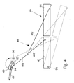
Figure 4 shows schematically a modification in accordance with the present invention of the baler shown inFigures 1 to 3 . -
Figures 1 to 3 are the same asFigures 1 to 3 ofEP 0974260 in which they are described fully. In the interest of brevity, the figures will be described below only to the extent necessary for an understanding of the present invention. - The
baler 10 is hitched at itsfront end 12 to a tractor and is supported onwheels 14. Thebaler 10 is powered from the power take off shaft of the tractor through aninput shaft 16 of a gearbox. - Crop lying in a field in windrows is collected from the ground by a
pickup 20 and is transferred in individual pre-compressed slices into abaling chamber 22 in which it is compressed further by a constantlyreciprocating plunger 24. When the compressed crop package in the baling chamber reaches the desired length, needles 26 and knotters 28 tie strands around the package to form a bale. The completed bale remains in thebaling chamber 22 and is incrementally pushed out of therear end 30 of thebaling chamber 22 by the action of theplunger 24 as the next bale is being formed. - The
rear end 30 of the baler is high off the ground and if bales were to be dropped from that height onto the ground they would be damaged. Abale chute 40 is used to lower bales onto the ground. The bale chute is formed of afront portion 42, pivotable to therear end 30 of thebaler 10 about anaxis 70 transverse to the direction of travel of thebaler 10 and arear portion 44 pivotable to the rear end of thefront portion 42. - The pivoting of the
front portion 42 is to allow the bale chute to be stowed in a vertical transport position. In the operating position shown inFigures 2 and 3 , the rear portion is supported by asuspension 46, made up of tworigid links flexible chain link 46c, level with the floor of the balingchamber 22. - The
rear portion 44 can tilt under the weight of a bale from the position shown inFigure 2 to that shown inFigure 3 . This allows thelast bale 50 to slide along therear portion 44 under the action of gravity without being pushed by thenext bale 52 and to drop onto the ground in a particular orientation. - So long as bales are being formed, the bale supported on the
front chute portion 42 will be pushed incrementally onto therear chute portion 44 until the point is reached where the latter portion tilts and causes the bale to slide onto the ground. However, a difficulty arises on completion of the baling operation in a field. - When there is no more crop to be baled, the last completed bale remains at the rear end of the baler. A reciprocating ejector mechanism is provided in the floor of the baling
chamber 22 to push the last bale out of the baling chamber onto thefront portion 42 of the bale chute. However, there is no mechanism in the bale chute to push it onto therear portion 44 from which it would fall automatically onto the ground and driver intervention as mentioned above is needed. - To overcome this problem, in the present invention a modification is made as shown in
Figure 4 to the attachment betweensuspension 46 and thebaler 10. Instead of the upper end of thelink 46a being connected to a bracket fixed to thebaler 10 near the top of the balingchamber 22, it is connected to alever 60 that can pivot about apin 62 that is fixed to thebaler 10 near the top of the balingchamber 22. Thelever 60 has two end positions defined bystops baler 10 near thepin 62. The position of thelever 60 shown in solid lines in which it rests on thestop 64 is that adopted during normal operation. In this position, thebale chute 40 and thesuspension 46 adopt their normal operations as described above, which are also shown in solid lines. - When the last bale from a field is to be lowered to the ground without being pushed from behind, the
lever 60 is moved by anactuator 68, which is connected at one end to thelever 60 and at its other end to thebaler 10, to the position shown in dotted lines in which it rests against thestop 66. This movement results in thesuspension 46 and thebale chute 40 adopting the inclined position shown in dotted lines inFigure 4 . In this position, any bale resting on thefront portion 42 will slide under the action of gravity onto therear portion 44 which will tilt further and gently lower the bale to the ground without damage and without the need for the operator to leave the driver's cabin. - While the
actuator 68 is shown as being a remotely controlled hydraulic jack, it will be clear that an electric motor or a manually operated linkage could alternatively be employed to operate thelever 60. - The toggle action of the
lever 60 stems from the fact that the line of action of thesuspension 46 crosses thepin 62 that forms a pivot point during the movement of thelever 60 from one end position to the other. It is important, however, that the line of action of the actuator on the other hand should always remain on the same side of thepivot pin 62, to avoid locking thelever 60 in one end position. - The invention as defined in the claims is of course not limited to the exemplary embodiments as described and shown in the drawings, but can equally comprise combinations and alternatives that fall within the scope of the claims.
Claims (6)
- A square baler (10) comprising- a baling chamber (22) within which crop is compressed into a bales; and- a bale chute (40) for lowering completed bales onto the ground, wherein the bale chute (40) has a leading end connected to the rear end (30) of the baler (10) for pivoting movement between a raised transport position and a lowered operating position about an axis (70) transverse to the direction of travel of the baler (10), and a suspension (46) is provided between a point on the baler (10) above the transverse pivoting axis (70) of the bale chute (40) and a point on the bale chute (40) distant from the transverse pivoting axis (70) for supporting the bale chute (40) in substantially the same plane as the floor of the baling chamber (22) when in the lowered operating position, characterised in that the suspension (46) is connected to the baler (10) by way of a lever mechanism (60, 62, 64, 66) that is movable between a first position in which the bale chute (40) is supported in the operating position and a second position in which the bale chute (40) is inclined sufficiently to the horizontal to cause a bale resting on any part of the bale chute (40) to slide under the action of gravity along the bale chute (40) and to fall onto the ground from the trailing end of the bale chute (40).
- A square baler according to claim 1, characterised in that the bale chute (40) has a front portion (42) connected to the rear end (30) of the baler (10) and a rear portion (44) that tilts automatically relative to the front portion (42) under the weight of a bale.
- A square baler according to claim 1 or 2, characterised in that the lever mechanism (60, 62, 64, 66) has a toggle action, with two stable end positions lying one on each side of an unstable over centre position.
- A square baler according to any preceding claim, characterised in that the lever mechanism (60, 62, 64, 66) is movable between its end positions by means of a hydraulic actuator (68).
- A square baler according to any of claims 1 to 3, characterised in that the lever mechanism (60, 62, 64, 66) is movable between its end positions by means of an electric motor.
- A square baler according to any of claims 1 to 3, characterised in that the lever mechanism (60, 62, 64, 66) is movable between its end positions by means of a manually operable lever mechanism.
Applications Claiming Priority (2)
| Application Number | Priority Date | Filing Date | Title |
|---|---|---|---|
| BE2009/0314A BE1018759A3 (en) | 2009-05-19 | 2009-05-19 | A RECTANGULAR BALEN PRESS WITH AN IMPROVED EXCESSIVE TIP. |
| PCT/EP2010/056830 WO2010133603A1 (en) | 2009-05-19 | 2010-05-18 | Square baler with an improved bale chute |
Publications (2)
| Publication Number | Publication Date |
|---|---|
| EP2432311A1 EP2432311A1 (en) | 2012-03-28 |
| EP2432311B1 true EP2432311B1 (en) | 2013-03-27 |
Family
ID=41402162
Family Applications (1)
| Application Number | Title | Priority Date | Filing Date |
|---|---|---|---|
| EP10722332A Not-in-force EP2432311B1 (en) | 2009-05-19 | 2010-05-18 | Square baler with an improved bale chute |
Country Status (5)
| Country | Link |
|---|---|
| US (1) | US8522677B2 (en) |
| EP (1) | EP2432311B1 (en) |
| CN (1) | CN102395262B (en) |
| BE (1) | BE1018759A3 (en) |
| WO (1) | WO2010133603A1 (en) |
Families Citing this family (3)
| Publication number | Priority date | Publication date | Assignee | Title |
|---|---|---|---|---|
| NL1037742C2 (en) * | 2010-02-23 | 2011-08-24 | Forage Innovations Bv | Wrapper for wrapping bales of crop material. |
| BE1021100B1 (en) * | 2013-07-09 | 2016-01-29 | Cnh Industrial Belgium Nv | BALEN LOADING AGENTS |
| CN108055913A (en) * | 2018-01-23 | 2018-05-22 | 江苏沃得农业机械有限公司 | Stalk in stack unloads device after harvester threshing |
Family Cites Families (12)
| Publication number | Priority date | Publication date | Assignee | Title |
|---|---|---|---|---|
| US2625002A (en) * | 1950-07-12 | 1953-01-13 | Elmer G Prechel | Automatic self-dumping bale carrier |
| GB724771A (en) * | 1952-09-10 | 1955-02-23 | Loddon Engineering Company Ltd | Improvements in or relating to agricultural baling machines |
| DE2851117A1 (en) * | 1978-11-25 | 1980-06-12 | Karl Speidel | Collecting and distributing device for compressed bales - has lowerable support platform and pivot arm slide device |
| DE4436128A1 (en) * | 1994-09-27 | 1996-03-28 | Claas Ohg | Weighing device for balers |
| US5540144A (en) * | 1995-03-21 | 1996-07-30 | Hay & Forage Industries | Extrusion type square baler having selective bale ejector |
| DE29517425U1 (en) * | 1995-11-03 | 1996-01-11 | Maschinenfabriken Bernard Krone Gmbh, 48480 Spelle | Baler |
| NL1008400C2 (en) * | 1998-02-24 | 1999-08-25 | Meijer Ten Post Beheer B V | Bale collector with rotatable rear roller bed section. |
| GB2339719A (en) * | 1998-07-23 | 2000-02-09 | Ford New Holland Nv | Bale discharge means for a rectangular baler |
| EP0974260B1 (en) * | 1998-07-23 | 2003-12-03 | CNH Belgium N.V. | Movable bale discharge means for an agricultural baler |
| US7392644B2 (en) * | 2005-03-31 | 2008-07-01 | Cnh America Llc | Cotton packager and unloader door arrangement for mounting on a chassis of a cotton harvester |
| GB2444914A (en) * | 2006-12-19 | 2008-06-25 | Cnh Belgium Nv | Improvements in Agricultural Balers |
| CN201226678Y (en) * | 2007-08-04 | 2009-04-29 | 王双德 | Straw packaging recovery device mated with harvester |
-
2009
- 2009-05-19 BE BE2009/0314A patent/BE1018759A3/en not_active IP Right Cessation
-
2010
- 2010-05-18 EP EP10722332A patent/EP2432311B1/en not_active Not-in-force
- 2010-05-18 US US13/321,160 patent/US8522677B2/en not_active Expired - Fee Related
- 2010-05-18 CN CN201080016556.XA patent/CN102395262B/en not_active Expired - Fee Related
- 2010-05-18 WO PCT/EP2010/056830 patent/WO2010133603A1/en not_active Ceased
Also Published As
| Publication number | Publication date |
|---|---|
| EP2432311A1 (en) | 2012-03-28 |
| US8522677B2 (en) | 2013-09-03 |
| CN102395262A (en) | 2012-03-28 |
| US20120124958A1 (en) | 2012-05-24 |
| CN102395262B (en) | 2014-12-10 |
| BE1018759A3 (en) | 2011-08-02 |
| WO2010133603A1 (en) | 2010-11-25 |
Similar Documents
| Publication | Publication Date | Title |
|---|---|---|
| EP2974591B1 (en) | A carriage assembly, baler and a method for moving a bale from an agricultural baler to a carriage assembly | |
| AU783907B2 (en) | Cotton processing system and method of operation | |
| EP2974590B1 (en) | Carriage assembly, agricultural baler with such and method for moving a bale on a bale carriage | |
| EP2838340B1 (en) | Bale forming apparatus and method with a rear housing part pivotal about at least 90 degrees | |
| EP2974589B1 (en) | A carriage assembly, a baler and a method for deploying the carriage assembly | |
| EP2974593B1 (en) | Agricultural baler and method for coupling a bale carriage of a crop accumulator to an agricultural baler | |
| EP1731023B1 (en) | Bale ejection mechanism | |
| EP2959768B1 (en) | Continuous round baler with variable conveyor | |
| US3521762A (en) | Bale stacking apparatus | |
| EP2545765B1 (en) | Robust bale ejector system | |
| EP0974260B1 (en) | Movable bale discharge means for an agricultural baler | |
| US8522677B2 (en) | Square baler with an improved bale chute | |
| BE1020303A3 (en) | COMBINED PACKER AND STOWER. | |
| HU177636B (en) | Machine for making high size cylindric bales from hay or other harvested stover | |
| US12616100B2 (en) | Ejection chute for an agricultural baler | |
| GB2053081A (en) | Apparatus for packing and securing a plurality of bales into a stack | |
| EP1207739B1 (en) | A device for stacking the bales in a machine for making bales of grassy material and the like | |
| AU2010202808A1 (en) | Bale stack machine |
Legal Events
| Date | Code | Title | Description |
|---|---|---|---|
| PUAI | Public reference made under article 153(3) epc to a published international application that has entered the european phase |
Free format text: ORIGINAL CODE: 0009012 |
|
| 17P | Request for examination filed |
Effective date: 20111219 |
|
| AK | Designated contracting states |
Kind code of ref document: A1 Designated state(s): AL AT BE BG CH CY CZ DE DK EE ES FI FR GB GR HR HU IE IS IT LI LT LU LV MC MK MT NL NO PL PT RO SE SI SK SM TR |
|
| DAX | Request for extension of the european patent (deleted) | ||
| GRAP | Despatch of communication of intention to grant a patent |
Free format text: ORIGINAL CODE: EPIDOSNIGR1 |
|
| GRAS | Grant fee paid |
Free format text: ORIGINAL CODE: EPIDOSNIGR3 |
|
| GRAA | (expected) grant |
Free format text: ORIGINAL CODE: 0009210 |
|
| AK | Designated contracting states |
Kind code of ref document: B1 Designated state(s): AL AT BE BG CH CY CZ DE DK EE ES FI FR GB GR HR HU IE IS IT LI LT LU LV MC MK MT NL NO PL PT RO SE SI SK SM TR |
|
| REG | Reference to a national code |
Ref country code: GB Ref legal event code: FG4D |
|
| REG | Reference to a national code |
Ref country code: CH Ref legal event code: EP |
|
| REG | Reference to a national code |
Ref country code: AT Ref legal event code: REF Ref document number: 602759 Country of ref document: AT Kind code of ref document: T Effective date: 20130415 |
|
| REG | Reference to a national code |
Ref country code: IE Ref legal event code: FG4D |
|
| REG | Reference to a national code |
Ref country code: DE Ref legal event code: R096 Ref document number: 602010005819 Country of ref document: DE Effective date: 20130529 |
|
| REG | Reference to a national code |
Ref country code: NL Ref legal event code: T3 |
|
| PG25 | Lapsed in a contracting state [announced via postgrant information from national office to epo] |
Ref country code: NO Free format text: LAPSE BECAUSE OF FAILURE TO SUBMIT A TRANSLATION OF THE DESCRIPTION OR TO PAY THE FEE WITHIN THE PRESCRIBED TIME-LIMIT Effective date: 20130627 Ref country code: LT Free format text: LAPSE BECAUSE OF FAILURE TO SUBMIT A TRANSLATION OF THE DESCRIPTION OR TO PAY THE FEE WITHIN THE PRESCRIBED TIME-LIMIT Effective date: 20130327 Ref country code: SE Free format text: LAPSE BECAUSE OF FAILURE TO SUBMIT A TRANSLATION OF THE DESCRIPTION OR TO PAY THE FEE WITHIN THE PRESCRIBED TIME-LIMIT Effective date: 20130327 Ref country code: BG Free format text: LAPSE BECAUSE OF FAILURE TO SUBMIT A TRANSLATION OF THE DESCRIPTION OR TO PAY THE FEE WITHIN THE PRESCRIBED TIME-LIMIT Effective date: 20130627 |
|
| REG | Reference to a national code |
Ref country code: AT Ref legal event code: MK05 Ref document number: 602759 Country of ref document: AT Kind code of ref document: T Effective date: 20130327 |
|
| REG | Reference to a national code |
Ref country code: LT Ref legal event code: MG4D |
|
| PG25 | Lapsed in a contracting state [announced via postgrant information from national office to epo] |
Ref country code: GR Free format text: LAPSE BECAUSE OF FAILURE TO SUBMIT A TRANSLATION OF THE DESCRIPTION OR TO PAY THE FEE WITHIN THE PRESCRIBED TIME-LIMIT Effective date: 20130628 Ref country code: SI Free format text: LAPSE BECAUSE OF FAILURE TO SUBMIT A TRANSLATION OF THE DESCRIPTION OR TO PAY THE FEE WITHIN THE PRESCRIBED TIME-LIMIT Effective date: 20130327 Ref country code: FI Free format text: LAPSE BECAUSE OF FAILURE TO SUBMIT A TRANSLATION OF THE DESCRIPTION OR TO PAY THE FEE WITHIN THE PRESCRIBED TIME-LIMIT Effective date: 20130327 Ref country code: LV Free format text: LAPSE BECAUSE OF FAILURE TO SUBMIT A TRANSLATION OF THE DESCRIPTION OR TO PAY THE FEE WITHIN THE PRESCRIBED TIME-LIMIT Effective date: 20130327 |
|
| PG25 | Lapsed in a contracting state [announced via postgrant information from national office to epo] |
Ref country code: HR Free format text: LAPSE BECAUSE OF FAILURE TO SUBMIT A TRANSLATION OF THE DESCRIPTION OR TO PAY THE FEE WITHIN THE PRESCRIBED TIME-LIMIT Effective date: 20130327 |
|
| PG25 | Lapsed in a contracting state [announced via postgrant information from national office to epo] |
Ref country code: EE Free format text: LAPSE BECAUSE OF FAILURE TO SUBMIT A TRANSLATION OF THE DESCRIPTION OR TO PAY THE FEE WITHIN THE PRESCRIBED TIME-LIMIT Effective date: 20130327 Ref country code: SK Free format text: LAPSE BECAUSE OF FAILURE TO SUBMIT A TRANSLATION OF THE DESCRIPTION OR TO PAY THE FEE WITHIN THE PRESCRIBED TIME-LIMIT Effective date: 20130327 Ref country code: PT Free format text: LAPSE BECAUSE OF FAILURE TO SUBMIT A TRANSLATION OF THE DESCRIPTION OR TO PAY THE FEE WITHIN THE PRESCRIBED TIME-LIMIT Effective date: 20130729 Ref country code: ES Free format text: LAPSE BECAUSE OF FAILURE TO SUBMIT A TRANSLATION OF THE DESCRIPTION OR TO PAY THE FEE WITHIN THE PRESCRIBED TIME-LIMIT Effective date: 20130708 Ref country code: CZ Free format text: LAPSE BECAUSE OF FAILURE TO SUBMIT A TRANSLATION OF THE DESCRIPTION OR TO PAY THE FEE WITHIN THE PRESCRIBED TIME-LIMIT Effective date: 20130327 Ref country code: RO Free format text: LAPSE BECAUSE OF FAILURE TO SUBMIT A TRANSLATION OF THE DESCRIPTION OR TO PAY THE FEE WITHIN THE PRESCRIBED TIME-LIMIT Effective date: 20130327 Ref country code: AT Free format text: LAPSE BECAUSE OF FAILURE TO SUBMIT A TRANSLATION OF THE DESCRIPTION OR TO PAY THE FEE WITHIN THE PRESCRIBED TIME-LIMIT Effective date: 20130327 Ref country code: IS Free format text: LAPSE BECAUSE OF FAILURE TO SUBMIT A TRANSLATION OF THE DESCRIPTION OR TO PAY THE FEE WITHIN THE PRESCRIBED TIME-LIMIT Effective date: 20130727 |
|
| PG25 | Lapsed in a contracting state [announced via postgrant information from national office to epo] |
Ref country code: PL Free format text: LAPSE BECAUSE OF FAILURE TO SUBMIT A TRANSLATION OF THE DESCRIPTION OR TO PAY THE FEE WITHIN THE PRESCRIBED TIME-LIMIT Effective date: 20130327 Ref country code: CY Free format text: LAPSE BECAUSE OF FAILURE TO SUBMIT A TRANSLATION OF THE DESCRIPTION OR TO PAY THE FEE WITHIN THE PRESCRIBED TIME-LIMIT Effective date: 20130327 |
|
| PG25 | Lapsed in a contracting state [announced via postgrant information from national office to epo] |
Ref country code: MC Free format text: LAPSE BECAUSE OF FAILURE TO SUBMIT A TRANSLATION OF THE DESCRIPTION OR TO PAY THE FEE WITHIN THE PRESCRIBED TIME-LIMIT Effective date: 20130327 |
|
| PG25 | Lapsed in a contracting state [announced via postgrant information from national office to epo] |
Ref country code: DK Free format text: LAPSE BECAUSE OF FAILURE TO SUBMIT A TRANSLATION OF THE DESCRIPTION OR TO PAY THE FEE WITHIN THE PRESCRIBED TIME-LIMIT Effective date: 20130327 |
|
| PLBE | No opposition filed within time limit |
Free format text: ORIGINAL CODE: 0009261 |
|
| STAA | Information on the status of an ep patent application or granted ep patent |
Free format text: STATUS: NO OPPOSITION FILED WITHIN TIME LIMIT |
|
| REG | Reference to a national code |
Ref country code: IE Ref legal event code: MM4A |
|
| 26N | No opposition filed |
Effective date: 20140103 |
|
| REG | Reference to a national code |
Ref country code: DE Ref legal event code: R097 Ref document number: 602010005819 Country of ref document: DE Effective date: 20140103 |
|
| REG | Reference to a national code |
Ref country code: DE Ref legal event code: R082 Ref document number: 602010005819 Country of ref document: DE Representative=s name: PATENTANWAELTE WALLACH, KOCH & PARTNER, DE |
|
| PG25 | Lapsed in a contracting state [announced via postgrant information from national office to epo] |
Ref country code: IE Free format text: LAPSE BECAUSE OF NON-PAYMENT OF DUE FEES Effective date: 20130518 |
|
| REG | Reference to a national code |
Ref country code: DE Ref legal event code: R082 Ref document number: 602010005819 Country of ref document: DE Representative=s name: PATENTANWAELTE WALLACH, KOCH, DR. HAIBACH, FEL, DE Effective date: 20140428 Ref country code: DE Ref legal event code: R082 Ref document number: 602010005819 Country of ref document: DE Representative=s name: PATENTANWAELTE WALLACH, KOCH & PARTNER, DE Effective date: 20140428 Ref country code: DE Ref legal event code: R081 Ref document number: 602010005819 Country of ref document: DE Owner name: CNH INDUSTRIAL BELGIUM NV, BE Free format text: FORMER OWNER: CNH BELGIUM N.V., ZEDELGEM, BE Effective date: 20140428 |
|
| REG | Reference to a national code |
Ref country code: FR Ref legal event code: CD Owner name: CNH INDUSTRIAL BELGIUM NV Effective date: 20140725 |
|
| REG | Reference to a national code |
Ref country code: CH Ref legal event code: PL |
|
| PG25 | Lapsed in a contracting state [announced via postgrant information from national office to epo] |
Ref country code: CH Free format text: LAPSE BECAUSE OF NON-PAYMENT OF DUE FEES Effective date: 20140531 Ref country code: LI Free format text: LAPSE BECAUSE OF NON-PAYMENT OF DUE FEES Effective date: 20140531 |
|
| PG25 | Lapsed in a contracting state [announced via postgrant information from national office to epo] |
Ref country code: MT Free format text: LAPSE BECAUSE OF FAILURE TO SUBMIT A TRANSLATION OF THE DESCRIPTION OR TO PAY THE FEE WITHIN THE PRESCRIBED TIME-LIMIT Effective date: 20130327 |
|
| PG25 | Lapsed in a contracting state [announced via postgrant information from national office to epo] |
Ref country code: SM Free format text: LAPSE BECAUSE OF FAILURE TO SUBMIT A TRANSLATION OF THE DESCRIPTION OR TO PAY THE FEE WITHIN THE PRESCRIBED TIME-LIMIT Effective date: 20130327 |
|
| PG25 | Lapsed in a contracting state [announced via postgrant information from national office to epo] |
Ref country code: TR Free format text: LAPSE BECAUSE OF FAILURE TO SUBMIT A TRANSLATION OF THE DESCRIPTION OR TO PAY THE FEE WITHIN THE PRESCRIBED TIME-LIMIT Effective date: 20130327 |
|
| REG | Reference to a national code |
Ref country code: NL Ref legal event code: TD Effective date: 20150714 |
|
| REG | Reference to a national code |
Ref country code: NL Ref legal event code: TD Effective date: 20150714 |
|
| PG25 | Lapsed in a contracting state [announced via postgrant information from national office to epo] |
Ref country code: LU Free format text: LAPSE BECAUSE OF NON-PAYMENT OF DUE FEES Effective date: 20130518 Ref country code: HU Free format text: LAPSE BECAUSE OF FAILURE TO SUBMIT A TRANSLATION OF THE DESCRIPTION OR TO PAY THE FEE WITHIN THE PRESCRIBED TIME-LIMIT; INVALID AB INITIO Effective date: 20100518 Ref country code: MK Free format text: LAPSE BECAUSE OF FAILURE TO SUBMIT A TRANSLATION OF THE DESCRIPTION OR TO PAY THE FEE WITHIN THE PRESCRIBED TIME-LIMIT Effective date: 20130327 |
|
| REG | Reference to a national code |
Ref country code: FR Ref legal event code: PLFP Year of fee payment: 7 |
|
| REG | Reference to a national code |
Ref country code: FR Ref legal event code: PLFP Year of fee payment: 8 |
|
| REG | Reference to a national code |
Ref country code: FR Ref legal event code: PLFP Year of fee payment: 9 |
|
| PG25 | Lapsed in a contracting state [announced via postgrant information from national office to epo] |
Ref country code: AL Free format text: LAPSE BECAUSE OF FAILURE TO SUBMIT A TRANSLATION OF THE DESCRIPTION OR TO PAY THE FEE WITHIN THE PRESCRIBED TIME-LIMIT Effective date: 20130327 |
|
| REG | Reference to a national code |
Ref country code: DE Ref legal event code: R082 Ref document number: 602010005819 Country of ref document: DE Representative=s name: MEISSNER BOLTE PATENTANWAELTE RECHTSANWAELTE P, DE |
|
| PGFP | Annual fee paid to national office [announced via postgrant information from national office to epo] |
Ref country code: NL Payment date: 20210325 Year of fee payment: 12 |
|
| PGFP | Annual fee paid to national office [announced via postgrant information from national office to epo] |
Ref country code: GB Payment date: 20210522 Year of fee payment: 12 |
|
| REG | Reference to a national code |
Ref country code: NL Ref legal event code: MM Effective date: 20220601 |
|
| GBPC | Gb: european patent ceased through non-payment of renewal fee |
Effective date: 20220518 |
|
| PG25 | Lapsed in a contracting state [announced via postgrant information from national office to epo] |
Ref country code: GB Free format text: LAPSE BECAUSE OF NON-PAYMENT OF DUE FEES Effective date: 20220518 |
|
| PG25 | Lapsed in a contracting state [announced via postgrant information from national office to epo] |
Ref country code: NL Free format text: LAPSE BECAUSE OF NON-PAYMENT OF DUE FEES Effective date: 20220601 |
|
| PGFP | Annual fee paid to national office [announced via postgrant information from national office to epo] |
Ref country code: IT Payment date: 20230510 Year of fee payment: 14 Ref country code: FR Payment date: 20230523 Year of fee payment: 14 Ref country code: DE Payment date: 20230525 Year of fee payment: 14 |
|
| PGFP | Annual fee paid to national office [announced via postgrant information from national office to epo] |
Ref country code: BE Payment date: 20230525 Year of fee payment: 14 |
|
| REG | Reference to a national code |
Ref country code: DE Ref legal event code: R119 Ref document number: 602010005819 Country of ref document: DE |
|
| REG | Reference to a national code |
Ref country code: BE Ref legal event code: MM Effective date: 20240531 |
|
| PG25 | Lapsed in a contracting state [announced via postgrant information from national office to epo] |
Ref country code: DE Free format text: LAPSE BECAUSE OF NON-PAYMENT OF DUE FEES Effective date: 20241203 |
|
| PG25 | Lapsed in a contracting state [announced via postgrant information from national office to epo] |
Ref country code: BE Free format text: LAPSE BECAUSE OF NON-PAYMENT OF DUE FEES Effective date: 20240531 |
|
| PG25 | Lapsed in a contracting state [announced via postgrant information from national office to epo] |
Ref country code: FR Free format text: LAPSE BECAUSE OF NON-PAYMENT OF DUE FEES Effective date: 20240531 |
|
| PG25 | Lapsed in a contracting state [announced via postgrant information from national office to epo] |
Ref country code: IT Free format text: LAPSE BECAUSE OF NON-PAYMENT OF DUE FEES Effective date: 20240518 |