EP2432113A1 - Power generating device and control method therefor - Google Patents
Power generating device and control method therefor Download PDFInfo
- Publication number
- EP2432113A1 EP2432113A1 EP09752709A EP09752709A EP2432113A1 EP 2432113 A1 EP2432113 A1 EP 2432113A1 EP 09752709 A EP09752709 A EP 09752709A EP 09752709 A EP09752709 A EP 09752709A EP 2432113 A1 EP2432113 A1 EP 2432113A1
- Authority
- EP
- European Patent Office
- Prior art keywords
- voltage
- utility grid
- reactive current
- correlation information
- current
- Prior art date
- Legal status (The legal status is an assumption and is not a legal conclusion. Google has not performed a legal analysis and makes no representation as to the accuracy of the status listed.)
- Granted
Links
Images


Classifications
-
- H—ELECTRICITY
- H02—GENERATION; CONVERSION OR DISTRIBUTION OF ELECTRIC POWER
- H02P—CONTROL OR REGULATION OF ELECTRIC MOTORS, ELECTRIC GENERATORS OR DYNAMO-ELECTRIC CONVERTERS; CONTROLLING TRANSFORMERS, REACTORS OR CHOKE COILS
- H02P9/00—Arrangements for controlling electric generators for the purpose of obtaining a desired output
- H02P9/10—Control effected upon generator excitation circuit to reduce harmful effects of overloads or transients, e.g. sudden application of load, sudden removal of load, sudden change of load
- H02P9/102—Control effected upon generator excitation circuit to reduce harmful effects of overloads or transients, e.g. sudden application of load, sudden removal of load, sudden change of load for limiting effects of transients
-
- H—ELECTRICITY
- H02—GENERATION; CONVERSION OR DISTRIBUTION OF ELECTRIC POWER
- H02J—ELECTRIC POWER NETWORKS; CIRCUIT ARRANGEMENTS OR SYSTEMS FOR SUPPLYING OR DISTRIBUTING ELECTRIC POWER; SYSTEMS FOR STORING ELECTRIC ENERGY
- H02J3/00—Circuit arrangements for AC mains or AC distribution networks
- H02J3/12—Arrangements for adjusting voltage in AC networks by changing a characteristic of the network load
- H02J3/16—Arrangements for adjusting voltage in AC networks by changing a characteristic of the network load by adjustment of reactive power
-
- H—ELECTRICITY
- H02—GENERATION; CONVERSION OR DISTRIBUTION OF ELECTRIC POWER
- H02J—ELECTRIC POWER NETWORKS; CIRCUIT ARRANGEMENTS OR SYSTEMS FOR SUPPLYING OR DISTRIBUTING ELECTRIC POWER; SYSTEMS FOR STORING ELECTRIC ENERGY
- H02J3/00—Circuit arrangements for AC mains or AC distribution networks
- H02J3/18—Arrangements for adjusting, eliminating or compensating reactive power in networks
- H02J3/1821—Arrangements for adjusting, eliminating or compensating reactive power in networks using shunt compensators
- H02J3/1835—Arrangements for adjusting, eliminating or compensating reactive power in networks using shunt compensators with stepless control
- H02J3/1842—Arrangements for adjusting, eliminating or compensating reactive power in networks using shunt compensators with stepless control having reactive elements actively controlled by bridge converters, e.g. active filters or static compensators [STATCOM]
- H02J3/185—Arrangements for adjusting, eliminating or compensating reactive power in networks using shunt compensators with stepless control having reactive elements actively controlled by bridge converters, e.g. active filters or static compensators [STATCOM] the reactive elements being purely inductive, e.g. superconductive magnetic energy storage [SMES] systems
-
- H—ELECTRICITY
- H02—GENERATION; CONVERSION OR DISTRIBUTION OF ELECTRIC POWER
- H02J—ELECTRIC POWER NETWORKS; CIRCUIT ARRANGEMENTS OR SYSTEMS FOR SUPPLYING OR DISTRIBUTING ELECTRIC POWER; SYSTEMS FOR STORING ELECTRIC ENERGY
- H02J3/00—Circuit arrangements for AC mains or AC distribution networks
- H02J3/38—Arrangements for feeding a single network from two or more generators or sources in parallel; Arrangements for feeding already energised networks from additional generators or sources in parallel
- H02J3/381—Dispersed generators
-
- H—ELECTRICITY
- H02—GENERATION; CONVERSION OR DISTRIBUTION OF ELECTRIC POWER
- H02J—ELECTRIC POWER NETWORKS; CIRCUIT ARRANGEMENTS OR SYSTEMS FOR SUPPLYING OR DISTRIBUTING ELECTRIC POWER; SYSTEMS FOR STORING ELECTRIC ENERGY
- H02J3/00—Circuit arrangements for AC mains or AC distribution networks
- H02J3/38—Arrangements for feeding a single network from two or more generators or sources in parallel; Arrangements for feeding already energised networks from additional generators or sources in parallel
- H02J3/46—Controlling the sharing of generated power between the generators, sources or networks
- H02J3/50—Controlling the sharing of reactive power
-
- H—ELECTRICITY
- H02—GENERATION; CONVERSION OR DISTRIBUTION OF ELECTRIC POWER
- H02J—ELECTRIC POWER NETWORKS; CIRCUIT ARRANGEMENTS OR SYSTEMS FOR SUPPLYING OR DISTRIBUTING ELECTRIC POWER; SYSTEMS FOR STORING ELECTRIC ENERGY
- H02J2101/00—Supply or distribution of decentralised, dispersed or local electric power generation
- H02J2101/20—Dispersed power generation using renewable energy sources
- H02J2101/28—Wind energy
-
- H—ELECTRICITY
- H02—GENERATION; CONVERSION OR DISTRIBUTION OF ELECTRIC POWER
- H02P—CONTROL OR REGULATION OF ELECTRIC MOTORS, ELECTRIC GENERATORS OR DYNAMO-ELECTRIC CONVERTERS; CONTROLLING TRANSFORMERS, REACTORS OR CHOKE COILS
- H02P2101/00—Special adaptation of control arrangements for generators
- H02P2101/15—Special adaptation of control arrangements for generators for wind-driven turbines
-
- Y—GENERAL TAGGING OF NEW TECHNOLOGICAL DEVELOPMENTS; GENERAL TAGGING OF CROSS-SECTIONAL TECHNOLOGIES SPANNING OVER SEVERAL SECTIONS OF THE IPC; TECHNICAL SUBJECTS COVERED BY FORMER USPC CROSS-REFERENCE ART COLLECTIONS [XRACs] AND DIGESTS
- Y02—TECHNOLOGIES OR APPLICATIONS FOR MITIGATION OR ADAPTATION AGAINST CLIMATE CHANGE
- Y02E—REDUCTION OF GREENHOUSE GAS [GHG] EMISSIONS, RELATED TO ENERGY GENERATION, TRANSMISSION OR DISTRIBUTION
- Y02E10/00—Energy generation through renewable energy sources
- Y02E10/70—Wind energy
- Y02E10/76—Power conversion electric or electronic aspects
-
- Y—GENERAL TAGGING OF NEW TECHNOLOGICAL DEVELOPMENTS; GENERAL TAGGING OF CROSS-SECTIONAL TECHNOLOGIES SPANNING OVER SEVERAL SECTIONS OF THE IPC; TECHNICAL SUBJECTS COVERED BY FORMER USPC CROSS-REFERENCE ART COLLECTIONS [XRACs] AND DIGESTS
- Y02—TECHNOLOGIES OR APPLICATIONS FOR MITIGATION OR ADAPTATION AGAINST CLIMATE CHANGE
- Y02E—REDUCTION OF GREENHOUSE GAS [GHG] EMISSIONS, RELATED TO ENERGY GENERATION, TRANSMISSION OR DISTRIBUTION
- Y02E40/00—Technologies for an efficient electrical power generation, transmission or distribution
- Y02E40/20—Active power filtering [APF]
-
- Y—GENERAL TAGGING OF NEW TECHNOLOGICAL DEVELOPMENTS; GENERAL TAGGING OF CROSS-SECTIONAL TECHNOLOGIES SPANNING OVER SEVERAL SECTIONS OF THE IPC; TECHNICAL SUBJECTS COVERED BY FORMER USPC CROSS-REFERENCE ART COLLECTIONS [XRACs] AND DIGESTS
- Y02—TECHNOLOGIES OR APPLICATIONS FOR MITIGATION OR ADAPTATION AGAINST CLIMATE CHANGE
- Y02E—REDUCTION OF GREENHOUSE GAS [GHG] EMISSIONS, RELATED TO ENERGY GENERATION, TRANSMISSION OR DISTRIBUTION
- Y02E40/00—Technologies for an efficient electrical power generation, transmission or distribution
- Y02E40/30—Reactive power compensation
Definitions
- the present invention relates to a generating apparatus and a control method thereof.
- a relationship between a variation in the voltage of the utility grid and an amount of reactive current to be supplied (absorbed) in response to the variation is uniquely given by a table or the like, and this table is determined based on simulations performed at the time of installation of the wind turbine generator.
- the reactive current is supplied based on the table obtained by the simulations and the voltage of the utility grid gradually recovers according to the table, the voltage of the utility grid may become saturated and stabilized before the voltage recovers to the reference voltage in some cases.
- the present invention has been made to solve the above problem, and it is an object thereof to provide a generating apparatus and a control method the apparatus for reliably and swiftly restore voltage of a utility grid decreased due to a utility grid failure or the like to reference voltage.
- the present invention employs the following sections.
- a first aspect of the present invention recites a generating apparatus including: a generator connected to a utility grid; a voltage detecting section for detecting voltage of the utility grid; and a control section for determining reactive current corresponding to the voltage obtained from the voltage detecting section based on voltage current correlation information in which the voltage of the utility grid and the reactive current to be supplied to the utility grid are correlated with each other and controlling the electric power converting section to regulate the reactive current to be supplied to or absorbed from the utility grid, the apparatus further including an information changing section for changing the voltage current correlation information to increase an amount of reactive current with respect to a variation in the voltage in the voltage current correlation information, in the case where the voltage of the utility grid is not in a predetermined range set in advance after a predetermined time period has passed since the voltage of the utility grid varied by a predetermined amount or more.
- the control section determines the reactive current corresponding to the obtained voltage based on the voltage current correlation information in which the voltage of the utility grid and the reactive current to be supplied to the utility grid are correlated with each other and controls the electric power converting section to supply or absorb the determined reactive current to or from the utility grid.
- the information changing section changes the voltage current correlation information to increase the amount of the reactive current with respect to the variation in the voltage in the voltage current correlation information, in the case where the voltage of the utility grid is not in the predetermined range set in advance after the predetermined time period has passed since the voltage of the utility grid varied by the predetermined amount or more.
- the electric power converting section is controlled based on the voltage current correlation information changed to increase the amount of the reactive current with respect to the variation in the voltage in the case where the voltage of the utility grid varied by the predetermined amount or more as described above, it is possible to further speed up supply or absorption of the reactive current to bring the voltage of the utility grid close to the predetermined range set in advance, when it is impossible to supply or absorb sufficiently the reactive current by controlling the reactive current based on the voltage current correlation information before the change. In this way, it is possible to swiftly stabilize the utility grid voltage.
- the information changing section may be capable of changing the amount of the reactive current with respect to the variation in the voltage in the voltage current correlation information based on a difference between the reference voltage and the voltage value of the utility grid after the predetermined time period has passed since the utility grid varied by the predetermined amount or more.
- a second aspect of the present invention recites a control method of a generating apparatus including: a generator connected to a utility grid; a voltage detecting section for detecting voltage of the utility grid; and a control section for determining reactive current corresponding to the voltage obtained from the voltage detecting section based on voltage current correlation information in which the voltage of the utility grid and the reactive current to be supplied to the utility grid are correlated with each other and controlling the electric power converting section to regulate the reactive current to be supplied to or absorbed from the utility grid, the method including the step of changing the voltage current correlation information to increase an amount of the reactive current with respect to a variation in the voltage in the voltage current correlation information, in the case where the voltage of the utility grid is not in a predetermined range set in advance after a predetermined time period has passed since the voltage of the utility grid varied by a predetermined amount or more.
- the present invention it is possible to reliably and swiftly restore the voltage of the utility grid, which decreased due to a utility grid failure or the like, to the reference voltage.
- FIG. 1 is a block diagram showing an example of a generator 6 provided to a wind turbine generator and components around the generator 6.
- a wind turbine generator 1 includes wind turbine blades 4, a gear 5, the generator 6, an electric power converting section 20, a control section 21, an information changing section 22, a voltage detecting section 27, a blade control section 23, and a main control section 24.
- the generator 6 is connected to a utility grid 2.
- a rotor of the generator 6 is joined to a wind turbine rotor (not shown) with the gear 5 interposed therebetween.
- the generator (induction machine) 6 is formed so that electric power generated by the generator 6 can be outputted to the utility grid 2 from both of a stator coil and a rotor coil.
- the generator 6 has the stator coil connected to the utility grid 2 and the rotor coil connected to the utility grid 2 with the electric power converting section 20 interposed therebetween.
- the voltage detecting section 27 is provided on an electric power line that connects the generator 6 to the utility grid 2, and detects voltage of the utility grid 2. The voltage measured by the voltage detecting section 27 is provided to the control section 21.
- the electric power converting section 20 includes a converter 14, a DC bus 15, and an inverter 16, and converts AC power received from the rotor coil into AC power adapted to a frequency of the utility grid 2.
- the converter 14 converts the AC power generated in the rotor coil into DC current and outputs the DC current to the DC bus 15.
- the inverter 16 converts the DC power received from the DC bus 15 into the AC power at the frequency same as that of the utility grid 2 and outputs the AC power.
- the electric power converting section 20 also has a function of converting AC power received from the utility grid 2 into AC power adapted to a frequency of the rotor coil.
- the inverter 16 converts the AC power into DC power and outputs the DC power to the DC bus 15.
- the converter 14 converts the DC power received from the DC bus 15 into the AC power adapted to the frequency of the rotor coil and supplies the AC power to the rotor coil of the generator 6.
- the control section 21 has voltage current correlation information in which the voltage of the utility grid 2 and the reactive current to be supplied to or absorbed from the utility grid 2 are correlated with each other, and determines an amount of the reactive current corresponding to the voltage obtained from the voltage detecting section 27, and controls the electric power converting section 20 to supply or absorb the determined reactive current to or from the utility grid 2 based on the voltage current correlation information. More specifically, the control section 21 determines the reactive current that corresponds to an output voltage V measured by the voltage detecting section 27 and is to be supplied to or absorbed from the utility grid 2. Furthermore, the control section 21 controls a PWM (Pulse Width Modulation) signal for the converter 14 or the inverter 16, and controls regulation of the reactive current.
- PWM Pulse Width Modulation
- FIG. 2 shows an example of information which the control section 21 includes and in which the voltage of the utility grid and the reactive current are correlated with each other.
- a horizontal axis represents the voltage of the utility grid as a ratio to reference voltage (Pu: per unit), and the voltage is equal to 1.0 Pu that is the reference voltage at an intersection point of the horizontal axis with a vertical axis.
- the left side of 1.0 Pu on the horizontal axis in the drawing represents the utility grid voltage lower than the reference voltage, and the right side of 1.0 Pu in the drawing represents the utility grid voltage higher than the reference voltage.
- the vertical axis sets no regulation of the reactive current as a reference (in other words, the intersection point of the vertical axis with the horizontal axis is 0 Pu) and represents an amount of the reactive current (Pu) to be regulated with respect to the reference.
- a lower side of 0 Pu on the vertical axis in the drawing represents an amount of the reactive current to be supplied from the generator to the utility grid
- an upper side of 0 Pu in the drawing represents an amount of the reactive current to be absorbed from the utility grid to the generator.
- the control section 21 causes the generator 6 to supply the reactive current to the utility grid 2 when the measured utility grid voltage is lower than the reference voltage, and reduces the reactive current to be supplied to the utility grid 2 as the utility grid voltage approaches the reference voltage.
- the control section 21 causes the generator 6 to absorb the reactive current from the utility grid 2, and reduces the reactive current to be absorbed from the utility grid 2 as the utility grid voltage approaches the reference voltage.
- the information changing section 22 changes the voltage current correlation information such that the amount of the reactive current is increased with respect to the variation in the voltage in the voltage current correlation information.
- time elapsed from detection of passage of the predetermined time period to the change of the voltage current correlation information is from several milliseconds to several hundred milliseconds.
- the predetermined range of the voltage of the utility grid 2 is ⁇ 10% with respect to the reference voltage, for example.
- the information changing section 22 may change the amount of the reactive current with respect to the variation in the voltage in the voltage current correlation information based on a difference between the voltage value of the utility grid 2 and the reference voltage after a predetermined time period has passed since the voltage of the utility grid 2 varied by a predetermined amount or more.
- a slope of the graph is preferably set to be larger (steeper).
- the slope of the graph is preferably set to be smaller (gentler) than that of the graph for midnight.
- the blade control section 23 controls a pitch angle ⁇ of the wind turbine blades 4 in response to a pitch command ⁇ * from the main control section 24. More specifically, the blade control section 23 controls the pitch angle ⁇ of the wind turbine blades 4 so as to be equated to the pitch command ⁇ *. Along with the control of the converter 14 and the inverter 16, the blade control section 23 controls the pitch angle of the wind turbine blades 4. In other words, the blade control section 23 controls the pitch angle of the wind turbine blades 4 so as to be equated to a pitch angle determined based on a required output of the electric power converting section 20.
- the control section 21 determines whether or not the voltage value detected by the voltage detecting section 27 is different from the specified reference voltage by a predetermined amount or more. As a result, in the case where a failure or the like occurred in the utility grid and the utility grid voltage decreased abruptly to cause a voltage variation equal to or greater than the predetermined amount from the reference voltage, the control section 21 controls the reactive current based on the voltage current correlation information shown in FIG.
- control section 21 determines the reactive current corresponding to the voltage detected by the voltage detecting section 27 based on the voltage current correlation information and controls the electric power converting section 20 to output the determined reactive current to the utility grid 2 so as to actuate the converter 14 or the inverter 16 (step SA2 in FIG. 4 ).
- the control section 21 calculates a ratio of the present voltage value with respect to 1.0 Pu as the reference. For example, in the case where the voltage value detected by the voltage detecting section 27 is half the reference voltage, the control section 21 reads a value of the reactive current corresponding to 0.5 Pu in the voltage current correlation information shown in FIG. 2 . As a result, the value -1.0 Pu, for example, is read as the reactive current.
- the control section 21 controls the electric power converting section 20 to supply the reactive current of 1.0 to the utility grid 2.
- the inverter 16 in the electric power converting section 20 generates current having a 90° phase lead with respect to the voltage, and this reactive current is supplied to the utility grid 2.
- the voltage of the utility grid 2 is increased gradually.
- the control section 21 determines whether or not the voltage value newly detected by the voltage detecting section 27 is in the predetermined range from the reference voltage. In the case where the detected voltage value is not in the predetermined range as a result of the determination (step SA3 in FIG. 4 ), the information changing section 22 changes the voltage current correlation information presently used by the control section 21. More specifically, the information changing section 22 changes the voltage current correlation information so that the amount of the reactive current corresponding to the variation in the voltage of the utility grid 2 becomes larger than that in the voltage current correlation information (a broken line) before the change as shown in FIG. 3 . In FIG. 3 , the voltage current correlation information after the change is shown in a solid line.
- the control section 21 obtains the reactive current (e.g., -1.0 pu) corresponding to the present voltage (e.g., 0.8 pu) of the utility grid 2 based on the changed voltage current correlation information, and controls the electric power converting section 20 based on the reactive current.
- the current having a 90° phase lead with respect to the voltage is generated and supplied to the utility grid 2.
- the reactive current is supplied to the utility grid 2 and the utility grid voltage approaches the reference voltage to fall within (converge into) the predetermined voltage range (e.g., the voltage range of ⁇ 10 percent (0.9 to 1.1 Pu) from the reference voltage 1.0 Pu)
- the utility grid voltage is considered to be stabilized.
- step SA6 in FIG. 4 the control section 21 restores the voltage current correlation information to that before the change, and controls the reactive current based on the voltage current correlation information before the change.
- step SA7 in FIG. 4 operation is stopped.
- the voltage current correlation information is changed so that the amount of the reactive current with respect to the variation in the voltage becomes greater, and the reactive current to be supplied to the utility grid 2 is controlled based on the changed voltage current correlation information.
- the voltage-current correlation information is changed in order to abruptly change an amount of the reactive current to be supplied/absorbed. Therefore, it is possible to swiftly shift the voltage of the utility grid 2 to the reference voltage.
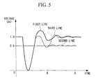
- FIG. 5 shows an exemplary graph showing recovery of the voltage of the utility grid 2 on a time series.
- an ideal graph on how the utility grid voltage approaches the predetermined voltage range set in advance after the drop is a first line and it takes A seconds for the voltage of the utility grid 2 to reach 1.0 Pu equal to the reference value.
- the amount of the reactive current reduces in the course of the utility grid voltage approaching the predetermined range (the range in which the utility grid voltage is considered to be stabilized).
- the voltage recovery performance correspondingly reduces and the utility grid voltage cannot reach (converge into) the predetermined range (a second line in FIG. 5 ).
- time required to change the voltage current correlation information is from several milliseconds to several hundred milliseconds, it is possible to promptly restore the utility grid even taking into consideration the time required to change the voltage current correlation information, as compared with restoring of the utility grid by supplying the reactive current without changing the voltage current correlation information.
- the information changing section 22 changes the voltage current correlation information only once in the description of the wind turbine generator 1 in the present embodiment, the number of times the voltage current correlation information is changed is not especially limited.
- the voltage current correlation information may be changed again, and may be changed repeatedly until the utility grid voltage becomes stable.
- the present invention is not limited thereto.
- the voltage current correlation information may be provided in a form of an arithmetic expression, a table, or the like.
Landscapes
- Engineering & Computer Science (AREA)
- Power Engineering (AREA)
- Control Of Eletrric Generators (AREA)
- Supply And Distribution Of Alternating Current (AREA)
- Control Of Electrical Variables (AREA)
Abstract
Description
- The present invention relates to a generating apparatus and a control method thereof.
- Conventionally, in the case where a utility grid failure occurs in a wind power generating system for interconnecting a wind turbine generator, voltage of a utility grid varies. In order to restore the varied voltage to reference voltage, reactive current is supplied from a generator to the utility grid or reactive current is absorbed from the utility grid into the generator.
- Patent Document 1:
US Patent Application, Publication No. 2007/0273155 - A relationship between a variation in the voltage of the utility grid and an amount of reactive current to be supplied (absorbed) in response to the variation is uniquely given by a table or the like, and this table is determined based on simulations performed at the time of installation of the wind turbine generator.
However, even in the case where the reactive current is supplied based on the table obtained by the simulations and the voltage of the utility grid gradually recovers according to the table, the voltage of the utility grid may become saturated and stabilized before the voltage recovers to the reference voltage in some cases. - In this case, even though the electric power supplier needs to supply more reactive current to restore the voltage of the utility grid to the reference voltage, it is impossible to supply (absorb) any more reactive current to the utility grid once the voltage has become stable. In other words, even in the case where control is carried out in order to restore the voltage of the utility grid based on the table determined by simulations or the like, the result in the actual environment is not the same as that in the simulations and it is impossible to reliably restore the voltage of the utility grid upon the utility grid failure or the like.
- The present invention has been made to solve the above problem, and it is an object thereof to provide a generating apparatus and a control method the apparatus for reliably and swiftly restore voltage of a utility grid decreased due to a utility grid failure or the like to reference voltage.
- In order to achieve the above object, the present invention employs the following sections.
- A first aspect of the present invention recites a generating apparatus including: a generator connected to a utility grid; a voltage detecting section for detecting voltage of the utility grid; and a control section for determining reactive current corresponding to the voltage obtained from the voltage detecting section based on voltage current correlation information in which the voltage of the utility grid and the reactive current to be supplied to the utility grid are correlated with each other and controlling the electric power converting section to regulate the reactive current to be supplied to or absorbed from the utility grid, the apparatus further including an information changing section for changing the voltage current correlation information to increase an amount of reactive current with respect to a variation in the voltage in the voltage current correlation information, in the case where the voltage of the utility grid is not in a predetermined range set in advance after a predetermined time period has passed since the voltage of the utility grid varied by a predetermined amount or more.
- With this structure, when the voltage of the utility grid is detected by the voltage detecting section and the control section obtains the detected voltage, the control section determines the reactive current corresponding to the obtained voltage based on the voltage current correlation information in which the voltage of the utility grid and the reactive current to be supplied to the utility grid are correlated with each other and controls the electric power converting section to supply or absorb the determined reactive current to or from the utility grid. The information changing section changes the voltage current correlation information to increase the amount of the reactive current with respect to the variation in the voltage in the voltage current correlation information, in the case where the voltage of the utility grid is not in the predetermined range set in advance after the predetermined time period has passed since the voltage of the utility grid varied by the predetermined amount or more.
Because the electric power converting section is controlled based on the voltage current correlation information changed to increase the amount of the reactive current with respect to the variation in the voltage in the case where the voltage of the utility grid varied by the predetermined amount or more as described above, it is possible to further speed up supply or absorption of the reactive current to bring the voltage of the utility grid close to the predetermined range set in advance, when it is impossible to supply or absorb sufficiently the reactive current by controlling the reactive current based on the voltage current correlation information before the change. In this way, it is possible to swiftly stabilize the utility grid voltage. - In the above generating apparatus, the information changing section may be capable of changing the amount of the reactive current with respect to the variation in the voltage in the voltage current correlation information based on a difference between the reference voltage and the voltage value of the utility grid after the predetermined time period has passed since the utility grid varied by the predetermined amount or more.
- By changing the amount of the reactive current with respect to the variation in the voltage based on the difference between the voltage value of the utility grid and the reference voltage as described above, it is possible to supply or absorb the appropriate and necessary amount of the reactive current.
- A second aspect of the present invention recites a control method of a generating apparatus including: a generator connected to a utility grid; a voltage detecting section for detecting voltage of the utility grid; and a control section for determining reactive current corresponding to the voltage obtained from the voltage detecting section based on voltage current correlation information in which the voltage of the utility grid and the reactive current to be supplied to the utility grid are correlated with each other and controlling the electric power converting section to regulate the reactive current to be supplied to or absorbed from the utility grid, the method including the step of changing the voltage current correlation information to increase an amount of the reactive current with respect to a variation in the voltage in the voltage current correlation information, in the case where the voltage of the utility grid is not in a predetermined range set in advance after a predetermined time period has passed since the voltage of the utility grid varied by a predetermined amount or more.
- According to the present invention, it is possible to reliably and swiftly restore the voltage of the utility grid, which decreased due to a utility grid failure or the like, to the reference voltage.
-
- [
FIG. 1] FIG. 1 is a block diagram showing an example of a wind turbine generator according to an embodiment of the present invention. - [
FIG. 2] FIG. 2 is a graph showing an example of voltage current correlation information, before change, on a relationship between voltage of a utility grid and reactive current. - [
FIG. 3] FIG. 3 is a graph showing an example of voltage current correlation information, after the change, on the relationship between voltage of the utility grid and reactive current. - [
FIG. 4] FIG. 4 is a chart showing an operation flow of a control method of the wind turbine generator according to the present invention. - [
FIG. 5] FIG. 5 is an exemplary graph showing variation of the voltage of the utility grid on a time series. -
- 1:
- Wind turbine generator
- 2:
- Utility grid
- 14:
- Converter
- 15:
- DC bus
- 16:
- Inverter
- 20:
- Electric power converting section
- 21:
- Control section
- 22:
- Information changing section
- 27:
- Voltage detecting section
- An embodiment of a generating apparatus and a control method thereof according to the present invention will be described below with reference to the drawings.
-
FIG. 1 is a block diagram showing an example of a generator 6 provided to a wind turbine generator and components around the generator 6.
As shown inFIG. 1 , a wind turbine generator 1 includes wind turbine blades 4, a gear 5, the generator 6, an electricpower converting section 20, acontrol section 21, aninformation changing section 22, avoltage detecting section 27, ablade control section 23, and amain control section 24. The generator 6 is connected to autility grid 2. A rotor of the generator 6 is joined to a wind turbine rotor (not shown) with the gear 5 interposed therebetween. - In the present embodiment, the generator (induction machine) 6 is formed so that electric power generated by the generator 6 can be outputted to the
utility grid 2 from both of a stator coil and a rotor coil. Specifically, the generator 6 has the stator coil connected to theutility grid 2 and the rotor coil connected to theutility grid 2 with the electricpower converting section 20 interposed therebetween. - The
voltage detecting section 27 is provided on an electric power line that connects the generator 6 to theutility grid 2, and detects voltage of theutility grid 2. The voltage measured by thevoltage detecting section 27 is provided to thecontrol section 21. - The electric
power converting section 20 includes aconverter 14, aDC bus 15, and aninverter 16, and converts AC power received from the rotor coil into AC power adapted to a frequency of theutility grid 2. Theconverter 14 converts the AC power generated in the rotor coil into DC current and outputs the DC current to theDC bus 15. Theinverter 16 converts the DC power received from theDC bus 15 into the AC power at the frequency same as that of theutility grid 2 and outputs the AC power. - The electric
power converting section 20 also has a function of converting AC power received from theutility grid 2 into AC power adapted to a frequency of the rotor coil. In this case, theinverter 16 converts the AC power into DC power and outputs the DC power to theDC bus 15. Theconverter 14 converts the DC power received from theDC bus 15 into the AC power adapted to the frequency of the rotor coil and supplies the AC power to the rotor coil of the generator 6. - The
control section 21 has voltage current correlation information in which the voltage of theutility grid 2 and the reactive current to be supplied to or absorbed from theutility grid 2 are correlated with each other, and determines an amount of the reactive current corresponding to the voltage obtained from thevoltage detecting section 27, and controls the electricpower converting section 20 to supply or absorb the determined reactive current to or from theutility grid 2 based on the voltage current correlation information. More specifically, thecontrol section 21 determines the reactive current that corresponds to an output voltage V measured by thevoltage detecting section 27 and is to be supplied to or absorbed from theutility grid 2. Furthermore, thecontrol section 21 controls a PWM (Pulse Width Modulation) signal for theconverter 14 or theinverter 16, and controls regulation of the reactive current. -
FIG. 2 shows an example of information which thecontrol section 21 includes and in which the voltage of the utility grid and the reactive current are correlated with each other. InFIG. 2 , a horizontal axis represents the voltage of the utility grid as a ratio to reference voltage (Pu: per unit), and the voltage is equal to 1.0 Pu that is the reference voltage at an intersection point of the horizontal axis with a vertical axis. The left side of 1.0 Pu on the horizontal axis in the drawing represents the utility grid voltage lower than the reference voltage, and the right side of 1.0 Pu in the drawing represents the utility grid voltage higher than the reference voltage. - On the other hand, in
FIG. 2 , the vertical axis sets no regulation of the reactive current as a reference (in other words, the intersection point of the vertical axis with the horizontal axis is 0 Pu) and represents an amount of the reactive current (Pu) to be regulated with respect to the reference. For example, a lower side of 0 Pu on the vertical axis in the drawing represents an amount of the reactive current to be supplied from the generator to the utility grid, and an upper side of 0 Pu in the drawing represents an amount of the reactive current to be absorbed from the utility grid to the generator. - Based on the information shown in
FIG. 2 , thecontrol section 21 causes the generator 6 to supply the reactive current to theutility grid 2 when the measured utility grid voltage is lower than the reference voltage, and reduces the reactive current to be supplied to theutility grid 2 as the utility grid voltage approaches the reference voltage. When the measured utility grid voltage is higher than the reference voltage, thecontrol section 21 causes the generator 6 to absorb the reactive current from theutility grid 2, and reduces the reactive current to be absorbed from theutility grid 2 as the utility grid voltage approaches the reference voltage. - In the case where the voltage of the
utility grid 2 is not in a predetermined range set in advance after a predetermined time period has passed since the voltage of theutility grid 2 varied by a predetermined amount or more, theinformation changing section 22 changes the voltage current correlation information such that the amount of the reactive current is increased with respect to the variation in the voltage in the voltage current correlation information. For example, time elapsed from detection of passage of the predetermined time period to the change of the voltage current correlation information is from several milliseconds to several hundred milliseconds. The predetermined range of the voltage of theutility grid 2 is ±10% with respect to the reference voltage, for example. - Alternatively, the
information changing section 22 may change the amount of the reactive current with respect to the variation in the voltage in the voltage current correlation information based on a difference between the voltage value of theutility grid 2 and the reference voltage after a predetermined time period has passed since the voltage of theutility grid 2 varied by a predetermined amount or more.
For example, in the case where electric power demand is different at different time of the day, e.g., daytime, evening, or midnight, recovery performance for recovering to the reference voltage is low in the case of low electric power demand at midnight or the like, and therefore a slope of the graph is preferably set to be larger (steeper). In the case of high electric power demand in the daytime or evening, the recovery performance for recovering to the reference voltage is high, and therefore the slope of the graph is preferably set to be smaller (gentler) than that of the graph for midnight. - The
blade control section 23 controls a pitch angle β of the wind turbine blades 4 in response to a pitch command β* from themain control section 24. More specifically, theblade control section 23 controls the pitch angle β of the wind turbine blades 4 so as to be equated to the pitch command β*.
Along with the control of theconverter 14 and theinverter 16, theblade control section 23 controls the pitch angle of the wind turbine blades 4. In other words, theblade control section 23 controls the pitch angle of the wind turbine blades 4 so as to be equated to a pitch angle determined based on a required output of the electricpower converting section 20. - Next, operation of the wind turbine generator 1 according to the present embodiment in the case where the utility grid voltage decreases will be described with reference to
FIGS. 2 to 4 .
First, the voltage of theutility grid 2 is detected by thevoltage detecting section 27 and is outputted to the control section 21 (step SA1 inFIG. 4 ). Thecontrol section 21 determines whether or not the voltage value detected by thevoltage detecting section 27 is different from the specified reference voltage by a predetermined amount or more. As a result, in the case where a failure or the like occurred in the utility grid and the utility grid voltage decreased abruptly to cause a voltage variation equal to or greater than the predetermined amount from the reference voltage, thecontrol section 21 controls the reactive current based on the voltage current correlation information shown inFIG. 2 in which the voltage of the utility grid and the reactive current are correlated with each other. More specifically, thecontrol section 21 determines the reactive current corresponding to the voltage detected by thevoltage detecting section 27 based on the voltage current correlation information and controls the electricpower converting section 20 to output the determined reactive current to theutility grid 2 so as to actuate theconverter 14 or the inverter 16 (step SA2 inFIG. 4 ). - Based on the voltage of the
utility grid 2 detected by thevoltage detecting section 27, thecontrol section 21 calculates a ratio of the present voltage value with respect to 1.0 Pu as the reference. For example, in the case where the voltage value detected by thevoltage detecting section 27 is half the reference voltage, thecontrol section 21 reads a value of the reactive current corresponding to 0.5 Pu in the voltage current correlation information shown inFIG. 2 . As a result, the value -1.0 Pu, for example, is read as the reactive current. - Upon reading the value -1.0 Pu, the
control section 21 controls the electricpower converting section 20 to supply the reactive current of 1.0 to theutility grid 2. As a result, theinverter 16 in the electricpower converting section 20 generates current having a 90° phase lead with respect to the voltage, and this reactive current is supplied to theutility grid 2. By supplying the reactive current to theutility grid 2 in this manner, the voltage of theutility grid 2 is increased gradually. - Thereafter, after the predetermined time period has passed since the predetermined amount of or greater variation was detected in the voltage of the utility grid with respect to the reference voltage, the
control section 21 determines whether or not the voltage value newly detected by thevoltage detecting section 27 is in the predetermined range from the reference voltage. In the case where the detected voltage value is not in the predetermined range as a result of the determination (step SA3 inFIG. 4 ), theinformation changing section 22 changes the voltage current correlation information presently used by thecontrol section 21. More specifically, theinformation changing section 22 changes the voltage current correlation information so that the amount of the reactive current corresponding to the variation in the voltage of theutility grid 2 becomes larger than that in the voltage current correlation information (a broken line) before the change as shown inFIG. 3 . InFIG. 3 , the voltage current correlation information after the change is shown in a solid line. - When the voltage current correlation information is changed, the
control section 21 obtains the reactive current (e.g., -1.0 pu) corresponding to the present voltage (e.g., 0.8 pu) of theutility grid 2 based on the changed voltage current correlation information, and controls the electricpower converting section 20 based on the reactive current. As a result, the current having a 90° phase lead with respect to the voltage is generated and supplied to theutility grid 2. When the reactive current is supplied to theutility grid 2 and the utility grid voltage approaches the reference voltage to fall within (converge into) the predetermined voltage range (e.g., the voltage range of ±10 percent (0.9 to 1.1 Pu) from the reference voltage 1.0 Pu), the utility grid voltage is considered to be stabilized. When the electricpower converting section 20 is controlled based on the changed voltage current correlation information after the change and the utility grid voltage becomes stable (step SA6 inFIG. 4 ) in this manner, thecontrol section 21 restores the voltage current correlation information to that before the change, and controls the reactive current based on the voltage current correlation information before the change.
In the case where the utility grid does not become stable even after the control of the reactive current in the above manner, operation is stopped (step SA7 inFIG. 4 ). - As described above, according to the wind turbine generator 1 and the control method thereof in the present embodiment, when the utility grid voltage varied by the predetermined value or more and the voltage of the
utility grid 2 is not in the predetermined range (e.g., ±10% with respect to the reference voltage) set in advance after the predetermined time period has passed since the variation occured, the voltage current correlation information is changed so that the amount of the reactive current with respect to the variation in the voltage becomes greater, and the reactive current to be supplied to theutility grid 2 is controlled based on the changed voltage current correlation information. In this way, in the case where it is impossible to restore the utility grid voltage at a desired speed by carrying out control based on the voltage current correlation information before the change, the voltage-current correlation information is changed in order to abruptly change an amount of the reactive current to be supplied/absorbed. Therefore, it is possible to swiftly shift the voltage of theutility grid 2 to the reference voltage. -
FIG. 5 shows an exemplary graph showing recovery of the voltage of theutility grid 2 on a time series.
As shown inFIG. 5 , an ideal graph on how the utility grid voltage approaches the predetermined voltage range set in advance after the drop is a first line and it takes A seconds for the voltage of theutility grid 2 to reach 1.0 Pu equal to the reference value. However, in the case where the reactive current is supplied based on the voltage-current correlation information shown by 1b inFIG. 2 , the amount of the reactive current reduces in the course of the utility grid voltage approaching the predetermined range (the range in which the utility grid voltage is considered to be stabilized). As a result, the voltage recovery performance correspondingly reduces and the utility grid voltage cannot reach (converge into) the predetermined range (a second line inFIG. 5 ). - In this case, by changing the voltage current correlation information with the
information changing section 22 according to the present embodiment after the predetermined time period (B seconds inFIG. 5 ) has passed since the voltage decreased, the amount of the reactive current is increased as shown by 2b inFIG. 2 , the voltage recovery performance is enhanced, and the voltage of theutility grid 2 is brought close to the reference voltage. As a result, it is possible to swiftly bring the voltage of theutility grid 2 close to the reference voltage as shown by a third line inFIG. 5 , and the voltage of theutility grid 2 along the third line can more swiftly approach the predetermined range by the time the voltage of theutility grid 2 becomes 1.0 Pu equal to the reference value relative to that along the first line. - In this way, upon bringing the voltage of the
utility grid 2 close to the predetermined range when the voltage of theutility grid 2 decreases due to a power failure or the like, it is possible to prevent saturation of the voltage at a certain voltage value, which disables supply of the reactive current and delays recovery of the voltage of theutility grid 2 to the predetermined range. Instead, it is possible to reliably bring the voltage close to the reference voltage as well as swift recovery can be achieved. - Because time required to change the voltage current correlation information is from several milliseconds to several hundred milliseconds, it is possible to promptly restore the utility grid even taking into consideration the time required to change the voltage current correlation information, as compared with restoring of the utility grid by supplying the reactive current without changing the voltage current correlation information.
- Although the
information changing section 22 changes the voltage current correlation information only once in the description of the wind turbine generator 1 in the present embodiment, the number of times the voltage current correlation information is changed is not especially limited. For example, in the case where the utility grid voltage does not become stable after the change of the voltage current correlation information, the voltage current correlation information may be changed again, and may be changed repeatedly until the utility grid voltage becomes stable. - Although the voltage current correlation information kept by the
information changing section 22 is provided in a form of the graph, the present invention is not limited thereto. Alternatively, the voltage current correlation information may be provided in a form of an arithmetic expression, a table, or the like. - Although the embodiment of the present invention has been described in detail with reference to the drawings, a specific structure is not limited to that according to this embodiment and may include modifications in design without departing from a gist of the present invention.
Claims (3)
- A generating apparatus comprising: a generator connected to a utility grid; a voltage detecting section for detecting voltage of the utility grid; and a control section for determining reactive current corresponding to the voltage obtained from the voltage detecting section based on voltage current correlation information in which the voltage of the utility grid and the reactive current to be supplied to the utility grid are correlated with each other and controlling the electric power converting section to regulate the reactive current to be supplied to or absorbed from the utility grid,
the apparatus further comprising an information changing section for changing the voltage current correlation information to increase an amount of reactive current with respect to a variation in the voltage in the voltage current correlation information, in the case where the voltage of the utility grid is not in a predetermined range set in advance after a predetermined time period has passed since the voltage of the utility grid varied by a predetermined amount or more. - A generating apparatus according to claim 1, wherein the information changing section is capable of changing the amount of the reactive current with respect to the variation in the voltage in the voltage current correlation information based on a difference between the reference voltage and the voltage value of the utility grid after the predetermined time period has passed since the utility grid varied by the predetermined amount or more.
- A control method of a generator including: a generator connected to a utility grid; a voltage detecting section for detecting voltage of the utility grid; and a control section for determining reactive current corresponding to the voltage obtained from the voltage detecting section based on voltage current correlation information in which the voltage of the utility grid and the reactive current to be supplied to the utility grid are correlated with each other and controlling the electric power converting section to regulate the reactive current to be supplied to or absorbed from the utility grid,
the method comprising the step of changing the voltage current correlation information to increase an amount of the reactive current with respect to a variation in the voltage in the voltage current correlation information, in the case where the voltage of the utility grid is not in a predetermined range set in advance after a predetermined time period has passed since the voltage of the utility grid varied by a predetermined amount or more.
Applications Claiming Priority (1)
| Application Number | Priority Date | Filing Date | Title |
|---|---|---|---|
| PCT/JP2009/058546 WO2010125687A1 (en) | 2009-05-01 | 2009-05-01 | Power generating device and control method therefor |
Publications (3)
| Publication Number | Publication Date |
|---|---|
| EP2432113A1 true EP2432113A1 (en) | 2012-03-21 |
| EP2432113A4 EP2432113A4 (en) | 2013-12-18 |
| EP2432113B1 EP2432113B1 (en) | 2015-02-25 |
Family
ID=43031849
Family Applications (1)
| Application Number | Title | Priority Date | Filing Date |
|---|---|---|---|
| EP20090752709 Active EP2432113B1 (en) | 2009-05-01 | 2009-05-01 | Power generating device and control method therefor |
Country Status (8)
| Country | Link |
|---|---|
| US (1) | US8295988B2 (en) |
| EP (1) | EP2432113B1 (en) |
| JP (1) | JP4885280B2 (en) |
| KR (1) | KR101204545B1 (en) |
| CN (1) | CN102318182B (en) |
| BR (1) | BRPI0909215A2 (en) |
| CA (1) | CA2714887C (en) |
| WO (1) | WO2010125687A1 (en) |
Families Citing this family (17)
| Publication number | Priority date | Publication date | Assignee | Title |
|---|---|---|---|---|
| US20120056425A1 (en) * | 2010-09-02 | 2012-03-08 | Clipper Windpower, Inc. | Stand alone operation system for use with utility grade synchronous wind turbine generators |
| WO2012062323A2 (en) * | 2010-11-10 | 2012-05-18 | Vestas Wind Systems A/S | Method and system for operating a wind turbine |
| DK2482418T3 (en) * | 2011-02-01 | 2018-11-12 | Siemens Ag | Active desynchronization of switching inverters |
| JP5627529B2 (en) * | 2011-04-01 | 2014-11-19 | 三菱重工業株式会社 | Wind turbine generator control device, wind turbine generator, wind farm, and wind turbine generator control method |
| US9711964B2 (en) | 2011-09-26 | 2017-07-18 | General Electric Corporation | Method and system for operating a power generation and delivery system |
| WO2013073017A1 (en) * | 2011-11-16 | 2013-05-23 | 三菱重工業株式会社 | Wind power generation system and method for controlling same |
| JP2014050162A (en) * | 2012-08-30 | 2014-03-17 | Hitachi Ltd | Conversion device for windmill, control device for windmill, method for controlling conversion device for windmill |
| CN104704700B (en) | 2012-10-12 | 2018-08-07 | 西门子公司 | The method and controller of machine are generated for operating continuously multiple electric energy during high voltage condition |
| US20140343744A1 (en) * | 2013-03-14 | 2014-11-20 | The Powerwise Group Inc. | Autonomous smart grid demand measurement system and method |
| KR101569622B1 (en) * | 2014-05-14 | 2015-11-16 | 엘에스산전 주식회사 | Converter and operating method thereof |
| US9458830B2 (en) * | 2014-09-05 | 2016-10-04 | General Electric Company | System and method for improving reactive current response time in a wind turbine |
| CN109074113B (en) * | 2016-07-19 | 2020-11-03 | 惠普发展公司,有限责任合伙企业 | Power monitoring and reduction |
| US11031784B2 (en) | 2018-02-15 | 2021-06-08 | General Electric Company | Reactive current margin regulator for power systems |
| US10305283B1 (en) | 2018-02-22 | 2019-05-28 | General Electric Company | Power angle feedforward signal for phase locked loop in wind turbine power systems |
| EP3900144A1 (en) | 2018-12-20 | 2021-10-27 | Vestas Wind Systems A/S | Control of a renewable energy power plant to resume normal operation following a fault |
| EP4170845A4 (en) * | 2020-06-23 | 2023-07-19 | Mitsubishi Electric Corporation | CONTROL DEVICE FOR PHASE MODIFICATION EQUIPMENT AND CONTROL METHOD FOR PHASE MODIFICATION EQUIPMENT |
| CN113300417B (en) * | 2021-05-26 | 2022-05-20 | 华中科技大学 | Control method and system for enhancing synchronous stability of double-fed fan |
Family Cites Families (19)
| Publication number | Priority date | Publication date | Assignee | Title |
|---|---|---|---|---|
| JPH0527856A (en) | 1991-07-22 | 1993-02-05 | Toshiba Corp | Reactive power compensator |
| JP2891030B2 (en) | 1993-03-30 | 1999-05-17 | 三菱電機株式会社 | Secondary excitation device for AC excitation synchronous machine |
| JP3590276B2 (en) | 1998-10-22 | 2004-11-17 | 松下電器産業株式会社 | Reactive power compensator |
| JP2000175360A (en) | 1998-12-02 | 2000-06-23 | Nissin Electric Co Ltd | Inverse power flow method of power storing system |
| JP3873564B2 (en) * | 2000-02-28 | 2007-01-24 | 三菱電機株式会社 | Excitation control device and excitation control method |
| JP4204846B2 (en) * | 2002-10-31 | 2009-01-07 | 三菱電機株式会社 | Control unit for AC excitation generator motor |
| DE602004027668D1 (en) | 2004-03-12 | 2010-07-22 | Gen Electric | METHOD FOR OPERATING A FREQUENCY TRANSMITTER OF A GENERATOR AND A WIND ENERGY TURBINE WITH A GENERATOR OPERATED ACCORDING TO THE METHOD |
| US7417336B2 (en) * | 2004-08-31 | 2008-08-26 | Caterpillar Inc. | Combination current hysteresis and voltage hysteresis control for a power converter |
| TWI264864B (en) | 2005-04-08 | 2006-10-21 | Univ Chang Gung | Power flow calculation method of power grid with unified power flow controller |
| TWI290788B (en) | 2005-08-29 | 2007-12-01 | Kun Shan University Of Technol | A reactive power compensator device for compensating the reactive power of induction generator |
| US7560909B2 (en) * | 2005-11-14 | 2009-07-14 | Asahi Kasei Microsystems Co., Ltd. | Power converter using extrapolative conductance mode control |
| TWI336160B (en) | 2006-12-01 | 2011-01-11 | Ind Tech Res Inst | Hybrid power-generating device |
| JP4501958B2 (en) * | 2007-05-09 | 2010-07-14 | 株式会社日立製作所 | Wind power generation system and control method thereof |
| JP2008301584A (en) * | 2007-05-30 | 2008-12-11 | Hitachi Ltd | Wind power generation system and power converter control method |
| EP2017936B1 (en) * | 2007-07-16 | 2010-10-20 | Gamesa Innovation & Technology, S.L. | Wind power system and method of operating it |
| DE102007044601A1 (en) * | 2007-09-19 | 2009-04-09 | Repower Systems Ag | Wind farm with voltage regulation of wind turbines and operating procedures |
| US8213199B2 (en) * | 2007-11-30 | 2012-07-03 | Alencon Acquisition Co., Llc. | Multiphase grid synchronized regulated current source inverter systems |
| CA2715238A1 (en) * | 2008-02-15 | 2009-08-20 | Wind To Power System, S.L. | Series voltage compensator and method for series voltage compensation in electrical generators |
| US8120932B2 (en) * | 2008-07-01 | 2012-02-21 | American Superconductor Corporation | Low voltage ride through |
-
2009
- 2009-05-01 CN CN200980110532.8A patent/CN102318182B/en not_active Expired - Fee Related
- 2009-05-01 EP EP20090752709 patent/EP2432113B1/en active Active
- 2009-05-01 BR BRPI0909215-3A patent/BRPI0909215A2/en not_active IP Right Cessation
- 2009-05-01 CA CA2714887A patent/CA2714887C/en not_active Expired - Fee Related
- 2009-05-01 US US12/601,153 patent/US8295988B2/en active Active
- 2009-05-01 JP JP2009548925A patent/JP4885280B2/en active Active
- 2009-05-01 KR KR1020107020825A patent/KR101204545B1/en not_active Expired - Fee Related
- 2009-05-01 WO PCT/JP2009/058546 patent/WO2010125687A1/en not_active Ceased
Also Published As
| Publication number | Publication date |
|---|---|
| CN102318182A (en) | 2012-01-11 |
| BRPI0909215A2 (en) | 2015-08-25 |
| CA2714887C (en) | 2012-10-02 |
| JP4885280B2 (en) | 2012-02-29 |
| JPWO2010125687A1 (en) | 2012-10-25 |
| US8295988B2 (en) | 2012-10-23 |
| KR101204545B1 (en) | 2012-11-23 |
| EP2432113A4 (en) | 2013-12-18 |
| CN102318182B (en) | 2014-03-26 |
| US20120035774A1 (en) | 2012-02-09 |
| KR20110000631A (en) | 2011-01-04 |
| EP2432113B1 (en) | 2015-02-25 |
| CA2714887A1 (en) | 2010-11-01 |
| WO2010125687A1 (en) | 2010-11-04 |
Similar Documents
| Publication | Publication Date | Title |
|---|---|---|
| EP2432113B1 (en) | Power generating device and control method therefor | |
| CA2707921C (en) | Wind turbine generator and method of controlling the same | |
| US9503007B2 (en) | System and method for controlling a power generation system connected to a weak grid | |
| US9548690B2 (en) | System and method for adjusting current regulator gains applied within a power generation system | |
| KR102050174B1 (en) | How to adjust wind turbine power draw | |
| EP3075052B1 (en) | A wind power plant with improved rise time | |
| EP2626555B1 (en) | Method and arrangement for controlling a wind turbine using oscillation detection | |
| KR101207151B1 (en) | Power supply apparatus and method | |
| CN102904517A (en) | Maximum power tracking control method for excitation synchronous generator | |
| RU2599983C2 (en) | Method for controlling a power supply unit and a controller for a power supply unit | |
| JP5608809B2 (en) | Power converter | |
| EP2863512B1 (en) | Power system, operation method thereof and control device for power system | |
| CN114172188A (en) | System and method for controlling driveline damping during multiple low voltage ride through events | |
| KR101951117B1 (en) | Control System For Wind Power Generating | |
| AU2009342166A1 (en) | Generating apparatus and control method thereof | |
| KR20200088159A (en) | Grid-connected inverter and method for detecting islanding of grid-connected inverter | |
| JP2010115094A (en) | Individual operation detection device of inverter and method of detecting the individual operation | |
| KR20140034631A (en) | Simulator of wind power generation system | |
| KR102048164B1 (en) | How to adjust wind turbine power draw | |
| EP1626492B1 (en) | Method in frequency converter provided with voltage intermediate circuit, and frequency converter | |
| JP2017118764A (en) | Output control device for wind power generation | |
| EP3410556B1 (en) | Control method for protecting generators | |
| EP2346133B1 (en) | Converter device and method for converting electrical power | |
| TWI373897B (en) | ||
| CN107086607A (en) | Generator control unit and method |
Legal Events
| Date | Code | Title | Description |
|---|---|---|---|
| PUAI | Public reference made under article 153(3) epc to a published international application that has entered the european phase |
Free format text: ORIGINAL CODE: 0009012 |
|
| 17P | Request for examination filed |
Effective date: 20091130 |
|
| AK | Designated contracting states |
Kind code of ref document: A1 Designated state(s): AT BE BG CH CY CZ DE DK EE ES FI FR GB GR HR HU IE IS IT LI LT LU LV MC MK MT NL NO PL PT RO SE SI SK TR |
|
| DAX | Request for extension of the european patent (deleted) | ||
| A4 | Supplementary search report drawn up and despatched |
Effective date: 20131114 |
|
| RIC1 | Information provided on ipc code assigned before grant |
Ipc: H02J 3/18 20060101ALI20131108BHEP Ipc: H02P 9/10 20060101AFI20131108BHEP |
|
| GRAP | Despatch of communication of intention to grant a patent |
Free format text: ORIGINAL CODE: EPIDOSNIGR1 |
|
| RIC1 | Information provided on ipc code assigned before grant |
Ipc: H02P 9/10 20060101AFI20141007BHEP Ipc: H02J 3/18 20060101ALI20141007BHEP |
|
| INTG | Intention to grant announced |
Effective date: 20141105 |
|
| GRAS | Grant fee paid |
Free format text: ORIGINAL CODE: EPIDOSNIGR3 |
|
| GRAA | (expected) grant |
Free format text: ORIGINAL CODE: 0009210 |
|
| AK | Designated contracting states |
Kind code of ref document: B1 Designated state(s): AT BE BG CH CY CZ DE DK EE ES FI FR GB GR HR HU IE IS IT LI LT LU LV MC MK MT NL NO PL PT RO SE SI SK TR |
|
| REG | Reference to a national code |
Ref country code: GB Ref legal event code: FG4D |
|
| REG | Reference to a national code |
Ref country code: CH Ref legal event code: EP |
|
| REG | Reference to a national code |
Ref country code: IE Ref legal event code: FG4D |
|
| REG | Reference to a national code |
Ref country code: DE Ref legal event code: R096 Ref document number: 602009029563 Country of ref document: DE Effective date: 20150409 |
|
| REG | Reference to a national code |
Ref country code: AT Ref legal event code: REF Ref document number: 712727 Country of ref document: AT Kind code of ref document: T Effective date: 20150415 |
|
| REG | Reference to a national code |
Ref country code: NL Ref legal event code: VDEP Effective date: 20150225 |
|
| REG | Reference to a national code |
Ref country code: AT Ref legal event code: MK05 Ref document number: 712727 Country of ref document: AT Kind code of ref document: T Effective date: 20150225 |
|
| REG | Reference to a national code |
Ref country code: LT Ref legal event code: MG4D |
|
| PG25 | Lapsed in a contracting state [announced via postgrant information from national office to epo] |
Ref country code: FI Free format text: LAPSE BECAUSE OF FAILURE TO SUBMIT A TRANSLATION OF THE DESCRIPTION OR TO PAY THE FEE WITHIN THE PRESCRIBED TIME-LIMIT Effective date: 20150225 Ref country code: SE Free format text: LAPSE BECAUSE OF FAILURE TO SUBMIT A TRANSLATION OF THE DESCRIPTION OR TO PAY THE FEE WITHIN THE PRESCRIBED TIME-LIMIT Effective date: 20150225 Ref country code: HR Free format text: LAPSE BECAUSE OF FAILURE TO SUBMIT A TRANSLATION OF THE DESCRIPTION OR TO PAY THE FEE WITHIN THE PRESCRIBED TIME-LIMIT Effective date: 20150225 Ref country code: NO Free format text: LAPSE BECAUSE OF FAILURE TO SUBMIT A TRANSLATION OF THE DESCRIPTION OR TO PAY THE FEE WITHIN THE PRESCRIBED TIME-LIMIT Effective date: 20150525 Ref country code: LT Free format text: LAPSE BECAUSE OF FAILURE TO SUBMIT A TRANSLATION OF THE DESCRIPTION OR TO PAY THE FEE WITHIN THE PRESCRIBED TIME-LIMIT Effective date: 20150225 Ref country code: ES Free format text: LAPSE BECAUSE OF FAILURE TO SUBMIT A TRANSLATION OF THE DESCRIPTION OR TO PAY THE FEE WITHIN THE PRESCRIBED TIME-LIMIT Effective date: 20150225 |
|
| PG25 | Lapsed in a contracting state [announced via postgrant information from national office to epo] |
Ref country code: LV Free format text: LAPSE BECAUSE OF FAILURE TO SUBMIT A TRANSLATION OF THE DESCRIPTION OR TO PAY THE FEE WITHIN THE PRESCRIBED TIME-LIMIT Effective date: 20150225 Ref country code: GR Free format text: LAPSE BECAUSE OF FAILURE TO SUBMIT A TRANSLATION OF THE DESCRIPTION OR TO PAY THE FEE WITHIN THE PRESCRIBED TIME-LIMIT Effective date: 20150526 Ref country code: AT Free format text: LAPSE BECAUSE OF FAILURE TO SUBMIT A TRANSLATION OF THE DESCRIPTION OR TO PAY THE FEE WITHIN THE PRESCRIBED TIME-LIMIT Effective date: 20150225 Ref country code: IS Free format text: LAPSE BECAUSE OF FAILURE TO SUBMIT A TRANSLATION OF THE DESCRIPTION OR TO PAY THE FEE WITHIN THE PRESCRIBED TIME-LIMIT Effective date: 20150625 |
|
| PG25 | Lapsed in a contracting state [announced via postgrant information from national office to epo] |
Ref country code: NL Free format text: LAPSE BECAUSE OF FAILURE TO SUBMIT A TRANSLATION OF THE DESCRIPTION OR TO PAY THE FEE WITHIN THE PRESCRIBED TIME-LIMIT Effective date: 20150225 |
|
| PG25 | Lapsed in a contracting state [announced via postgrant information from national office to epo] |
Ref country code: CZ Free format text: LAPSE BECAUSE OF FAILURE TO SUBMIT A TRANSLATION OF THE DESCRIPTION OR TO PAY THE FEE WITHIN THE PRESCRIBED TIME-LIMIT Effective date: 20150225 Ref country code: RO Free format text: LAPSE BECAUSE OF FAILURE TO SUBMIT A TRANSLATION OF THE DESCRIPTION OR TO PAY THE FEE WITHIN THE PRESCRIBED TIME-LIMIT Effective date: 20150225 Ref country code: EE Free format text: LAPSE BECAUSE OF FAILURE TO SUBMIT A TRANSLATION OF THE DESCRIPTION OR TO PAY THE FEE WITHIN THE PRESCRIBED TIME-LIMIT Effective date: 20150225 Ref country code: DK Free format text: LAPSE BECAUSE OF FAILURE TO SUBMIT A TRANSLATION OF THE DESCRIPTION OR TO PAY THE FEE WITHIN THE PRESCRIBED TIME-LIMIT Effective date: 20150225 Ref country code: SK Free format text: LAPSE BECAUSE OF FAILURE TO SUBMIT A TRANSLATION OF THE DESCRIPTION OR TO PAY THE FEE WITHIN THE PRESCRIBED TIME-LIMIT Effective date: 20150225 |
|
| REG | Reference to a national code |
Ref country code: DE Ref legal event code: R097 Ref document number: 602009029563 Country of ref document: DE |
|
| PG25 | Lapsed in a contracting state [announced via postgrant information from national office to epo] |
Ref country code: PL Free format text: LAPSE BECAUSE OF FAILURE TO SUBMIT A TRANSLATION OF THE DESCRIPTION OR TO PAY THE FEE WITHIN THE PRESCRIBED TIME-LIMIT Effective date: 20150225 |
|
| PG25 | Lapsed in a contracting state [announced via postgrant information from national office to epo] |
Ref country code: IT Free format text: LAPSE BECAUSE OF FAILURE TO SUBMIT A TRANSLATION OF THE DESCRIPTION OR TO PAY THE FEE WITHIN THE PRESCRIBED TIME-LIMIT Effective date: 20150225 |
|
| REG | Reference to a national code |
Ref country code: CH Ref legal event code: PL |
|
| PLBE | No opposition filed within time limit |
Free format text: ORIGINAL CODE: 0009261 |
|
| STAA | Information on the status of an ep patent application or granted ep patent |
Free format text: STATUS: NO OPPOSITION FILED WITHIN TIME LIMIT |
|
| PG25 | Lapsed in a contracting state [announced via postgrant information from national office to epo] |
Ref country code: LU Free format text: LAPSE BECAUSE OF FAILURE TO SUBMIT A TRANSLATION OF THE DESCRIPTION OR TO PAY THE FEE WITHIN THE PRESCRIBED TIME-LIMIT Effective date: 20150501 Ref country code: LI Free format text: LAPSE BECAUSE OF NON-PAYMENT OF DUE FEES Effective date: 20150531 Ref country code: MC Free format text: LAPSE BECAUSE OF FAILURE TO SUBMIT A TRANSLATION OF THE DESCRIPTION OR TO PAY THE FEE WITHIN THE PRESCRIBED TIME-LIMIT Effective date: 20150225 Ref country code: CH Free format text: LAPSE BECAUSE OF NON-PAYMENT OF DUE FEES Effective date: 20150531 |
|
| 26N | No opposition filed |
Effective date: 20151126 |
|
| REG | Reference to a national code |
Ref country code: IE Ref legal event code: MM4A |
|
| PG25 | Lapsed in a contracting state [announced via postgrant information from national office to epo] |
Ref country code: SI Free format text: LAPSE BECAUSE OF FAILURE TO SUBMIT A TRANSLATION OF THE DESCRIPTION OR TO PAY THE FEE WITHIN THE PRESCRIBED TIME-LIMIT Effective date: 20150225 |
|
| REG | Reference to a national code |
Ref country code: FR Ref legal event code: PLFP Year of fee payment: 8 |
|
| PG25 | Lapsed in a contracting state [announced via postgrant information from national office to epo] |
Ref country code: IE Free format text: LAPSE BECAUSE OF NON-PAYMENT OF DUE FEES Effective date: 20150501 |
|
| PG25 | Lapsed in a contracting state [announced via postgrant information from national office to epo] |
Ref country code: BE Free format text: LAPSE BECAUSE OF FAILURE TO SUBMIT A TRANSLATION OF THE DESCRIPTION OR TO PAY THE FEE WITHIN THE PRESCRIBED TIME-LIMIT Effective date: 20150225 |
|
| PG25 | Lapsed in a contracting state [announced via postgrant information from national office to epo] |
Ref country code: MT Free format text: LAPSE BECAUSE OF FAILURE TO SUBMIT A TRANSLATION OF THE DESCRIPTION OR TO PAY THE FEE WITHIN THE PRESCRIBED TIME-LIMIT Effective date: 20150225 |
|
| REG | Reference to a national code |
Ref country code: FR Ref legal event code: PLFP Year of fee payment: 9 |
|
| PG25 | Lapsed in a contracting state [announced via postgrant information from national office to epo] |
Ref country code: BG Free format text: LAPSE BECAUSE OF FAILURE TO SUBMIT A TRANSLATION OF THE DESCRIPTION OR TO PAY THE FEE WITHIN THE PRESCRIBED TIME-LIMIT Effective date: 20150225 Ref country code: HU Free format text: LAPSE BECAUSE OF FAILURE TO SUBMIT A TRANSLATION OF THE DESCRIPTION OR TO PAY THE FEE WITHIN THE PRESCRIBED TIME-LIMIT; INVALID AB INITIO Effective date: 20090501 |
|
| PG25 | Lapsed in a contracting state [announced via postgrant information from national office to epo] |
Ref country code: CY Free format text: LAPSE BECAUSE OF FAILURE TO SUBMIT A TRANSLATION OF THE DESCRIPTION OR TO PAY THE FEE WITHIN THE PRESCRIBED TIME-LIMIT Effective date: 20150225 |
|
| PG25 | Lapsed in a contracting state [announced via postgrant information from national office to epo] |
Ref country code: PT Free format text: LAPSE BECAUSE OF FAILURE TO SUBMIT A TRANSLATION OF THE DESCRIPTION OR TO PAY THE FEE WITHIN THE PRESCRIBED TIME-LIMIT Effective date: 20150625 |
|
| PG25 | Lapsed in a contracting state [announced via postgrant information from national office to epo] |
Ref country code: TR Free format text: LAPSE BECAUSE OF FAILURE TO SUBMIT A TRANSLATION OF THE DESCRIPTION OR TO PAY THE FEE WITHIN THE PRESCRIBED TIME-LIMIT Effective date: 20150225 |
|
| REG | Reference to a national code |
Ref country code: FR Ref legal event code: PLFP Year of fee payment: 10 |
|
| PG25 | Lapsed in a contracting state [announced via postgrant information from national office to epo] |
Ref country code: MK Free format text: LAPSE BECAUSE OF FAILURE TO SUBMIT A TRANSLATION OF THE DESCRIPTION OR TO PAY THE FEE WITHIN THE PRESCRIBED TIME-LIMIT Effective date: 20150225 |
|
| REG | Reference to a national code |
Ref country code: DE Ref legal event code: R082 Ref document number: 602009029563 Country of ref document: DE Representative=s name: CBDL PATENTANWAELTE GBR, DE Ref country code: DE Ref legal event code: R082 Ref document number: 602009029563 Country of ref document: DE Representative=s name: CBDL PATENTANWAELTE EGBR, DE |
|
| REG | Reference to a national code |
Ref country code: FR Ref legal event code: PLFP Year of fee payment: 15 |
|
| PGFP | Annual fee paid to national office [announced via postgrant information from national office to epo] |
Ref country code: DE Payment date: 20250402 Year of fee payment: 17 |
|
| PGFP | Annual fee paid to national office [announced via postgrant information from national office to epo] |
Ref country code: FR Payment date: 20250401 Year of fee payment: 17 |
|
| PGFP | Annual fee paid to national office [announced via postgrant information from national office to epo] |
Ref country code: GB Payment date: 20260323 Year of fee payment: 18 |