EP2432087A2 - Apparatus and system for arc elmination and method of assembly - Google Patents
Apparatus and system for arc elmination and method of assembly Download PDFInfo
- Publication number
- EP2432087A2 EP2432087A2 EP11181040A EP11181040A EP2432087A2 EP 2432087 A2 EP2432087 A2 EP 2432087A2 EP 11181040 A EP11181040 A EP 11181040A EP 11181040 A EP11181040 A EP 11181040A EP 2432087 A2 EP2432087 A2 EP 2432087A2
- Authority
- EP
- European Patent Office
- Prior art keywords
- chamber
- plasma gun
- gun
- diameter
- ablative plasma
- Prior art date
- Legal status (The legal status is an assumption and is not a legal conclusion. Google has not performed a legal analysis and makes no representation as to the accuracy of the status listed.)
- Granted
Links
Images

Classifications
-
- H—ELECTRICITY
- H05—ELECTRIC TECHNIQUES NOT OTHERWISE PROVIDED FOR
- H05H—PLASMA TECHNIQUE; PRODUCTION OF ACCELERATED ELECTRICALLY-CHARGED PARTICLES OR OF NEUTRONS; PRODUCTION OR ACCELERATION OF NEUTRAL MOLECULAR OR ATOMIC BEAMS
- H05H1/00—Generating plasma; Handling plasma
- H05H1/24—Generating plasma
- H05H1/26—Plasma torches
- H05H1/32—Plasma torches using an arc
- H05H1/34—Details, e.g. electrodes, nozzles
- H05H1/3405—Arrangements for stabilising or constricting the arc, e.g. by an additional gas flow
-
- H—ELECTRICITY
- H01—ELECTRIC ELEMENTS
- H01T—SPARK GAPS; OVERVOLTAGE ARRESTERS USING SPARK GAPS; SPARKING PLUGS; CORONA DEVICES; GENERATING IONS TO BE INTRODUCED INTO NON-ENCLOSED GASES
- H01T2/00—Spark gaps comprising auxiliary triggering means
- H01T2/02—Spark gaps comprising auxiliary triggering means comprising a trigger electrode or an auxiliary spark gap
-
- C—CHEMISTRY; METALLURGY
- C23—COATING METALLIC MATERIAL; COATING MATERIAL WITH METALLIC MATERIAL; CHEMICAL SURFACE TREATMENT; DIFFUSION TREATMENT OF METALLIC MATERIAL; COATING BY VACUUM EVAPORATION, BY SPUTTERING, BY ION IMPLANTATION OR BY CHEMICAL VAPOUR DEPOSITION, IN GENERAL; INHIBITING CORROSION OF METALLIC MATERIAL OR INCRUSTATION IN GENERAL
- C23C—COATING METALLIC MATERIAL; COATING MATERIAL WITH METALLIC MATERIAL; SURFACE TREATMENT OF METALLIC MATERIAL BY DIFFUSION INTO THE SURFACE, BY CHEMICAL CONVERSION OR SUBSTITUTION; COATING BY VACUUM EVAPORATION, BY SPUTTERING, BY ION IMPLANTATION OR BY CHEMICAL VAPOUR DEPOSITION, IN GENERAL
- C23C14/00—Coating by vacuum evaporation, by sputtering or by ion implantation of the coating forming material
- C23C14/22—Coating by vacuum evaporation, by sputtering or by ion implantation of the coating forming material characterised by the process of coating
- C23C14/24—Vacuum evaporation
- C23C14/32—Vacuum evaporation by explosion; by evaporation and subsequent ionisation of the vapours, e.g. ion-plating
-
- Y—GENERAL TAGGING OF NEW TECHNOLOGICAL DEVELOPMENTS; GENERAL TAGGING OF CROSS-SECTIONAL TECHNOLOGIES SPANNING OVER SEVERAL SECTIONS OF THE IPC; TECHNICAL SUBJECTS COVERED BY FORMER USPC CROSS-REFERENCE ART COLLECTIONS [XRACs] AND DIGESTS
- Y10—TECHNICAL SUBJECTS COVERED BY FORMER USPC
- Y10T—TECHNICAL SUBJECTS COVERED BY FORMER US CLASSIFICATION
- Y10T29/00—Metal working
- Y10T29/49—Method of mechanical manufacture
- Y10T29/49826—Assembling or joining
Definitions
- the embodiments described herein relate generally to plasma guns and, more particularly, to ablative plasma guns for use in eliminating arc flashes.
- Electric arc devices may be used in a variety of applications including, for example, series capacitor protection, high power switches, acoustic generators, shock wave generators, pulsed plasma thrusters, and arc mitigation devices.
- Such known devices generally include two or more main electrodes separated by a gap of air. A bias voltage is then applied to the main electrodes across the gap.
- a bias voltage is then applied to the main electrodes across the gap.
- at least some known electric arc devices require the main electrodes to be positioned closely together. Contaminants, or even the natural impedance of the air in the gap, can lead to arc formation between the main electrodes at undesirable times, which can lead to a circuit breaker being tripped when it would be otherwise unnecessary.
- At least some known electric arc devices simply position the main electrodes further apart to avoid such false positive results.
- these devices are typically less reliable because of a less effective spread of plasma from a plasma gun.
- at least some known plasma guns provide a plasma spread that does not effectively promote effective dielectric breakdown and reduction of impedance in the gap of air between the main electrodes. Such plasma guns can therefore show a lower level of reliability.
- an ablative plasma gun includes a first portion having a first diameter and a second portion having a second diameter that is larger than the first diameter, wherein a chamber is defined by the first portion and the second portion.
- an arc flash elimination system in another aspect, includes a plurality of main electrodes, wherein each of the plurality of main electrodes is coupled to a different portion of an electrical circuit.
- the arc flash elimination system also includes an ablative plasma gun positioned with respect to the plurality of main electrodes.
- the ablative plasma gun includes a first portion having a first diameter and a second portion having a second diameter that is larger than the first diameter, wherein a chamber is defined by the first portion and the second portion.
- a method of assembling an arc flash elimination system includes coupling each of a plurality of main electrodes to a different portion of an electrical circuit, and positioning an ablative plasma gun with respect to the plurality of main electrodes.
- the ablative plasma gun includes a first portion having a first diameter and a second portion positioned above the first portion and having a second diameter that is larger than the first diameter, wherein a chamber defined by the first portion and the second portion.
- Exemplary embodiments of systems, methods, and apparatus for use in arc flash elimination by initiation of an isolated arc within a self-contained device are described herein. These embodiments provide an ablative plasma gun that includes a chamber having a first portion, or lower portion, having a first diameter, and a second portion, or upper portion, having a second diameter that is larger than the first diameter.
- This plasma gun design facilitates an increased reliability and enhances plasma breakdown and arc creation between main electrodes of an arc elimination system.
- the embodiments described herein provide a greater plasma spread after the arc is created between the main electrodes, which facilitates enhanced dielectric breakdown within a main gap between the main electrodes.
- the additional plasma spread and dielectric breakdown enable the arc elimination system to perform under a wider range of bias voltages between the main electrodes, including bias voltages as low as 200 volts, and at a wider range of impedances within the main gap.
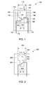
- Fig. 1 is a sectional view of an exemplary ablative plasma gun 100 that includes a cup 102 having a chamber 104 formed therein.
- Cup 102 includes a first portion 106 and a second portion 108 that is positioned with respect to first portion 106 to define chamber 104.
- second portion 108 is positioned above first portion 106.
- first portion 106 has a first diameter 110.
- first diameter 110 is approximately 0.138 inches.
- second portion 108 has a second diameter 112 that is larger than first diameter 110.
- second diameter 112 is approximately 0.221 inches.
- first portion 106 and second portion 108 are integrally formed and chamber 104 is defined therein.
- first portion 106 and second portion 108 are separately formed and are coupled together to form chamber 104.
- cup 102 is formed from an ablative material such as Polytetrafluoroethylene, Polyoxymethylene Polyamide, Poly-methyle methacralate (PMMA), other ablative polymers, or various mixtures of these materials.
- plasma gun 100 includes a cover 114 and a base 116.
- cover 114 is mounted on base 116 and is sized to enclose cup 102.
- cup 102 is positioned between base 116 and cover 114.
- a nozzle 118 is formed within cover 114.
- Nozzle 118 is positioned above an open end 120 of cup 102.
- cover 114 and/or base 116 are formed from the same ablative material as cup 102.
- cover 114 and/or base 116 are formed from one or more different ablative materials than cup 102, such as a refractory material or a ceramic material.
- plasma gun 100 includes a plurality of gun electrodes, including a first gun electrode 122 and a second gun electrode 124.
- First gun electrode 122 includes a first end 126 and second gun electrode 124 includes a second end 128 that each extend into chamber 104.
- first end 126 and second end 128 enter chamber 104 from radially opposite sides of chamber 104 about a central axis (not shown) of chamber 104.
- first end 126 and second end 128 are diagonally opposed across chamber 104, to define a gap for formation of an arc 130.
- Electrodes 122 and 124, or at least first end 126 and second end 128, may be formed from, for example, tungsten steel, tungsten, other high temperature refractory metals or alloys, carbon or graphite, or any other suitable materials that enable formation of arc 130.
- a pulse of electrical potential that is applied between electrodes 122 and 124 creates arc 130 that heats and ablates a portion of the ablative material of cup 102 to create a highly conductive plasma 132 at high pressure.
- Plasma 132 exits nozzle 118 in a spreading pattern at supersonic speed.
- Characteristics of plasma 132 may be controlled by dimensions of electrodes 122 and 124 and/or by a separation distance between first end 126 and second end 128. These characteristics of plasma 132 may also be controlled by the interior dimensions of chamber 104, the type of ablative material used to form cup 102, a trigger pulse shape, and/or a shape of nozzle 118.
- Fig. 2 is a sectional view of an alternative embodiment of an ablative plasma gun 200.
- plasma gun 200 is integrally formed from a single ablative material.
- Plasma gun 200 includes a chamber 202 that is defined by a first portion 204 and a second portion 206, which is positioned above first portion 204 and is integrally formed with first portion 204.
- first portion 204 has a first diameter 208 and second portion 206 has a second diameter 210.
- second diameter 210 is larger than first diameter 208.
- chamber 202 includes an open end 212 that partially extends across second portion 206 to form a nozzle 214.
- Fig. 3 is a simplified circuit diagram of an exemplary arc detection and elimination system 300 that includes an ablative plasma gun, such as plasma gun 100 of Fig. 1 .
- plasma gun 200 of Fig. 2 may also be used with system 300.
- system 300 also includes a main arc device 302, such as an arc containment device, that includes a plurality of main electrodes, such as two or more main electrodes 304 and 306 separated by a main gap 308 of air or another gas.
- main electrodes 304 and 306 are positioned approximately 0.275 inches apart due to second diameter 112 (shown in Fig. 1 ). This distance between main electrodes 304 and 306 enhances the response of arc elimination system 300 at low voltage.
- Each main electrode 304 and 306 is coupled to an electrically different portion 310 and 312, respectively, of a power circuit, such as different phases, neutral, or ground. Coupling main electrodes 304 and 306 to power circuit portions 310 and 312 provides a bias voltage 314 across main gap 308. In the exemplary embodiment, bias voltage 314 is between approximately 650 volts and approximately 815 volts.
- System 300 also includes a trigger circuit 316 that activates plasma gun 100 by transmitting an electrical pulse to plasma gun 100.
- system 300 includes a logic circuit 322, such as a relay or processor.
- logic circuit such as a relay or processor.
- logic circuit refer generally to any programmable system including systems and microcontrollers, reduced instruction set circuits (RISC), application specific integrated circuits (ASIC), programmable logic circuits, and any other circuit or processor capable of executing the functions described herein.
- RISC reduced instruction set circuits
- ASIC application specific integrated circuits
- programmable logic circuits and any other circuit or processor capable of executing the functions described herein.
- logic circuit 322 is communicatively coupled to one or more sensors 324, which may include light sensors, sound sensors, current sensors, voltage sensors, or any combination of these.
- system 300 includes one or more circuit breakers 326 that are communicatively coupled to logic circuit 322.
- sensors 324 detect an event that is indicative of an arc flash is on the power circuit.
- a current sensor can detect a rapid increase in current through a conductor of the power circuit
- a voltage sensor can detect a rapid decrease in voltage across multiple conductors of the power circuit
- a light sensor can detect a light flash.
- sensors 324 include a combination of current sensors, voltage sensors, and/or light sensors, such that multiple events may be detected within a specified time period to indicate the occurrence of an arc flash.
- sensors 324 transmit a signal representative of the detection to logic circuit 322.
- logic circuit 322 analyses the detection to determine whether the event is indicative of an arc flash or some other event, such as a trip of circuit breaker 326.
- logic circuit 322 determines that the event is indicative of an arc flash
- logic circuit 322 transmits an activation signal to trigger circuit 316.
- Main arc device 302 is then triggered by a voltage or current pulse to plasma gun 100 from trigger circuit 316.
- plasma gun 100 injects ablative plasma 318 into main gap 308, which reduces the impedance of main gap 308 sufficiently to enable initiation of a protective arc 320 between main electrodes 304 and 306.
- Arc 320 absorbs energy from the arc flash and opens circuit breaker 326, which quickly stops the arc flash and protects the power circuit.
- the term "main” refers generally to elements of a larger arc-based device to differentiate these elements from elements of plasma gun 100.
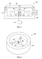
- Fig. 4 is a sectional view of arc elimination system 300
- Fig. 5 is a perspective view of arc elimination system 300.
- main arc device 302 and ablative plasma gun 100 are located in a pressure-tolerant case 328.
- case 328 includes one or more vents 330 for controlled pressure release.
- case 328 includes an outer cover 332 and an isolation container or shock shield 334 that defines an interior chamber 336 that safely contains the energy created by arc 320.
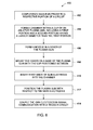
- Fig. 6 is a flowchart 400 that illustrates an exemplary method of assembling system 300 (shown in Figs. 3-5 ).
- each main electrode 304 and 306 (shown in Figs. 3-5 ) is coupled 402 to a different portion 310 and 312 (shown in Figs. 3 and 4 ) of an electrical circuit, such as a power circuit.
- the position of each main electrode 304 and 306 creates main gap 308 (shown in Figs. 3 and 4 ) that is filled with air or another gas.
- chamber 104 of ablative plasma gun 100 is formed 404 within cup 102 and nozzle 118 is formed 406 in cover 114 (each element shown in Fig. 1 ).
- Cover 114 is then mounted 408 on base 116 (shown in Fig. 1 ) such that cup 102 is positioned between base 116 and cover 114.
- plasma gun 200 is integrally formed from a single ablative material.
- chamber 202 is formed from the ablative material, including first portion 204 and second portion 206.
- first end 126 and second end 128 (both shown in Fig. 1 ) of gun electrodes 122 and 124 (shown in Fig. 1 ), respectively, are inserted 410 into chamber 104 such that first end 126 and second end 128 extend in radially opposite directions form a central axis of chamber 104.
- Ablative plasma gun 100 or, alternatively, ablative plasma gun 200 is then positioned 412 with respect to main electrodes 304 and 306.
- gun electrodes 122 and 124 are coupled 414 in signal communication to trigger circuit 316 (shown in Figs. 3 and 4 ).
Landscapes
- Chemical & Material Sciences (AREA)
- Engineering & Computer Science (AREA)
- Physics & Mathematics (AREA)
- Plasma & Fusion (AREA)
- Chemical Kinetics & Catalysis (AREA)
- Materials Engineering (AREA)
- Mechanical Engineering (AREA)
- Metallurgy (AREA)
- Organic Chemistry (AREA)
- Spectroscopy & Molecular Physics (AREA)
- Plasma Technology (AREA)
- Arc Welding In General (AREA)
Abstract
Description
- The embodiments described herein relate generally to plasma guns and, more particularly, to ablative plasma guns for use in eliminating arc flashes.
- Electric arc devices may be used in a variety of applications including, for example, series capacitor protection, high power switches, acoustic generators, shock wave generators, pulsed plasma thrusters, and arc mitigation devices. Such known devices generally include two or more main electrodes separated by a gap of air. A bias voltage is then applied to the main electrodes across the gap. However, at least some known electric arc devices require the main electrodes to be positioned closely together. Contaminants, or even the natural impedance of the air in the gap, can lead to arc formation between the main electrodes at undesirable times, which can lead to a circuit breaker being tripped when it would be otherwise unnecessary.
- Accordingly, at least some known electric arc devices simply position the main electrodes further apart to avoid such false positive results. However, these devices are typically less reliable because of a less effective spread of plasma from a plasma gun. For example, at least some known plasma guns provide a plasma spread that does not effectively promote effective dielectric breakdown and reduction of impedance in the gap of air between the main electrodes. Such plasma guns can therefore show a lower level of reliability.
- In one aspect, an ablative plasma gun includes a first portion having a first diameter and a second portion having a second diameter that is larger than the first diameter, wherein a chamber is defined by the first portion and the second portion.
- In another aspect, an arc flash elimination system includes a plurality of main electrodes, wherein each of the plurality of main electrodes is coupled to a different portion of an electrical circuit. The arc flash elimination system also includes an ablative plasma gun positioned with respect to the plurality of main electrodes. The ablative plasma gun includes a first portion having a first diameter and a second portion having a second diameter that is larger than the first diameter, wherein a chamber is defined by the first portion and the second portion.
- In another aspect, a method of assembling an arc flash elimination system includes coupling each of a plurality of main electrodes to a different portion of an electrical circuit, and positioning an ablative plasma gun with respect to the plurality of main electrodes. The ablative plasma gun includes a first portion having a first diameter and a second portion positioned above the first portion and having a second diameter that is larger than the first diameter, wherein a chamber defined by the first portion and the second portion.
-
-
Fig. 1 is a sectional view of an exemplary ablative plasma gun. -
Fig. 2 is a sectional view of an alternative embodiment of an ablative plasma gun. -
Fig. 3 is a simplified circuit diagram of an exemplary arc elimination system that includes the ablative plasma gun shown inFig. 1 or Fig. 2 . -
Fig. 4 is a sectional view of the arc elimination system shown inFig. 3 . -
Fig. 5 is a perspective view of the arc elimination system shown inFig. 3 . -
Fig. 6 is a flowchart that illustrates an exemplary method of assembling the arc elimination system shown inFigs. 3-5 . - Exemplary embodiments of systems, methods, and apparatus for use in arc flash elimination by initiation of an isolated arc within a self-contained device are described herein. These embodiments provide an ablative plasma gun that includes a chamber having a first portion, or lower portion, having a first diameter, and a second portion, or upper portion, having a second diameter that is larger than the first diameter. This plasma gun design facilitates an increased reliability and enhances plasma breakdown and arc creation between main electrodes of an arc elimination system. For example, the embodiments described herein provide a greater plasma spread after the arc is created between the main electrodes, which facilitates enhanced dielectric breakdown within a main gap between the main electrodes. The additional plasma spread and dielectric breakdown enable the arc elimination system to perform under a wider range of bias voltages between the main electrodes, including bias voltages as low as 200 volts, and at a wider range of impedances within the main gap.
-
Fig. 1 is a sectional view of an exemplaryablative plasma gun 100 that includes acup 102 having achamber 104 formed therein.Cup 102 includes afirst portion 106 and asecond portion 108 that is positioned with respect tofirst portion 106 to definechamber 104. For example, in the exemplary embodiment,second portion 108 is positioned abovefirst portion 106. Moreover,first portion 106 has afirst diameter 110. In the exemplary embodiment,first diameter 110 is approximately 0.138 inches. In addition,second portion 108 has asecond diameter 112 that is larger thanfirst diameter 110. In the exemplary embodiment,second diameter 112 is approximately 0.221 inches. It should be noted that any suitable measurements may be used forfirst diameter 110 and/orsecond diameter 112 that enableplasma gun 100 to function as described herein. Moreover, in the exemplary embodiment,first portion 106 andsecond portion 108 are integrally formed andchamber 104 is defined therein. In an alternative embodiment,first portion 106 andsecond portion 108 are separately formed and are coupled together to formchamber 104. In the exemplary embodiment,cup 102 is formed from an ablative material such as Polytetrafluoroethylene, Polyoxymethylene Polyamide, Poly-methyle methacralate (PMMA), other ablative polymers, or various mixtures of these materials. - Moreover,
plasma gun 100 includes acover 114 and abase 116. In the exemplary embodiment,cover 114 is mounted onbase 116 and is sized to enclosecup 102. Specifically,cup 102 is positioned betweenbase 116 andcover 114. In addition, anozzle 118 is formed withincover 114. Nozzle 118 is positioned above anopen end 120 ofcup 102. In the exemplary embodiment,cover 114 and/orbase 116 are formed from the same ablative material ascup 102. Alternatively,cover 114 and/orbase 116 are formed from one or more different ablative materials thancup 102, such as a refractory material or a ceramic material. - Furthermore, in the exemplary embodiment,
plasma gun 100 includes a plurality of gun electrodes, including afirst gun electrode 122 and asecond gun electrode 124.First gun electrode 122 includes afirst end 126 andsecond gun electrode 124 includes asecond end 128 that each extend intochamber 104. For example,first end 126 andsecond end 128enter chamber 104 from radially opposite sides ofchamber 104 about a central axis (not shown) ofchamber 104. Moreover,first end 126 andsecond end 128 are diagonally opposed acrosschamber 104, to define a gap for formation of anarc 130.Electrodes first end 126 andsecond end 128, may be formed from, for example, tungsten steel, tungsten, other high temperature refractory metals or alloys, carbon or graphite, or any other suitable materials that enable formation ofarc 130. A pulse of electrical potential that is applied betweenelectrodes arc 130 that heats and ablates a portion of the ablative material ofcup 102 to create a highlyconductive plasma 132 at high pressure.Plasma 132exits nozzle 118 in a spreading pattern at supersonic speed. Characteristics ofplasma 132, such as velocity, ion concentration, and an area of spread, may be controlled by dimensions ofelectrodes first end 126 andsecond end 128. These characteristics ofplasma 132 may also be controlled by the interior dimensions ofchamber 104, the type of ablative material used to formcup 102, a trigger pulse shape, and/or a shape ofnozzle 118. -
Fig. 2 is a sectional view of an alternative embodiment of anablative plasma gun 200. As shown inFig. 2 ,plasma gun 200 is integrally formed from a single ablative material.Plasma gun 200 includes achamber 202 that is defined by afirst portion 204 and asecond portion 206, which is positioned abovefirst portion 204 and is integrally formed withfirst portion 204. Moreover,first portion 204 has afirst diameter 208 andsecond portion 206 has asecond diameter 210. In the exemplary embodiment ofFig. 2 ,second diameter 210 is larger thanfirst diameter 208. Moreover, as shown inFig. 2 ,chamber 202 includes anopen end 212 that partially extends acrosssecond portion 206 to form anozzle 214. -
Fig. 3 is a simplified circuit diagram of an exemplary arc detection andelimination system 300 that includes an ablative plasma gun, such asplasma gun 100 ofFig. 1 . However, it should be understood thatplasma gun 200 ofFig. 2 may also be used withsystem 300. In the exemplary embodiment,system 300 also includes amain arc device 302, such as an arc containment device, that includes a plurality of main electrodes, such as two or moremain electrodes main gap 308 of air or another gas. For example,main electrodes Fig. 1 ). This distance betweenmain electrodes arc elimination system 300 at low voltage. Eachmain electrode different portion main electrodes power circuit portions bias voltage 314 acrossmain gap 308. In the exemplary embodiment,bias voltage 314 is between approximately 650 volts and approximately 815 volts.System 300 also includes atrigger circuit 316 that activatesplasma gun 100 by transmitting an electrical pulse toplasma gun 100. - Moreover,
system 300 includes alogic circuit 322, such as a relay or processor. It should be understood that the terms "logic circuit" and "processor" refer generally to any programmable system including systems and microcontrollers, reduced instruction set circuits (RISC), application specific integrated circuits (ASIC), programmable logic circuits, and any other circuit or processor capable of executing the functions described herein. The above examples are exemplary only, and thus are not intended to limit in any way the definition and/or meaning of these terms. In the exemplaryembodiment logic circuit 322 is communicatively coupled to one ormore sensors 324, which may include light sensors, sound sensors, current sensors, voltage sensors, or any combination of these. Furthermore,system 300 includes one ormore circuit breakers 326 that are communicatively coupled tologic circuit 322. - During operation,
sensors 324 detect an event that is indicative of an arc flash is on the power circuit. For example, a current sensor can detect a rapid increase in current through a conductor of the power circuit, a voltage sensor can detect a rapid decrease in voltage across multiple conductors of the power circuit, or a light sensor can detect a light flash. In some embodiments,sensors 324 include a combination of current sensors, voltage sensors, and/or light sensors, such that multiple events may be detected within a specified time period to indicate the occurrence of an arc flash. In the exemplary embodiment,sensors 324 transmit a signal representative of the detection tologic circuit 322. In some embodiments,logic circuit 322 analyses the detection to determine whether the event is indicative of an arc flash or some other event, such as a trip ofcircuit breaker 326. Whenlogic circuit 322 determines that the event is indicative of an arc flash,logic circuit 322 transmits an activation signal to triggercircuit 316.Main arc device 302 is then triggered by a voltage or current pulse toplasma gun 100 fromtrigger circuit 316. In response to the voltage or current pulse,plasma gun 100 injectsablative plasma 318 intomain gap 308, which reduces the impedance ofmain gap 308 sufficiently to enable initiation of aprotective arc 320 betweenmain electrodes Arc 320 absorbs energy from the arc flash and openscircuit breaker 326, which quickly stops the arc flash and protects the power circuit. As used herein, the term "main" refers generally to elements of a larger arc-based device to differentiate these elements from elements ofplasma gun 100. -
Fig. 4 is a sectional view ofarc elimination system 300, andFig. 5 is a perspective view ofarc elimination system 300. In the exemplary embodiment,main arc device 302 andablative plasma gun 100 are located in a pressure-tolerant case 328. In some embodiments,case 328 includes one ormore vents 330 for controlled pressure release. Moreover,case 328 includes anouter cover 332 and an isolation container orshock shield 334 that defines aninterior chamber 336 that safely contains the energy created byarc 320. -
Fig. 6 is aflowchart 400 that illustrates an exemplary method of assembling system 300 (shown inFigs. 3-5 ). In the exemplary embodiment, eachmain electrode 304 and 306 (shown inFigs. 3-5 ) is coupled 402 to adifferent portion 310 and 312 (shown inFigs. 3 and4 ) of an electrical circuit, such as a power circuit. The position of eachmain electrode Figs. 3 and4 ) that is filled with air or another gas. Moreover,chamber 104 ofablative plasma gun 100 is formed 404 withincup 102 andnozzle 118 is formed 406 in cover 114 (each element shown inFig. 1 ). Cover 114 is then mounted 408 on base 116 (shown inFig. 1 ) such thatcup 102 is positioned betweenbase 116 andcover 114. Alternatively, and referring toFig. 2 ,plasma gun 200 is integrally formed from a single ablative material. In such an embodiment,chamber 202 is formed from the ablative material, includingfirst portion 204 andsecond portion 206. - Referring again to
Fig. 6 , and in the exemplary embodiment,first end 126 and second end 128 (both shown inFig. 1 ) ofgun electrodes 122 and 124 (shown inFig. 1 ), respectively, are inserted 410 intochamber 104 such thatfirst end 126 andsecond end 128 extend in radially opposite directions form a central axis ofchamber 104.Ablative plasma gun 100 or, alternatively,ablative plasma gun 200 is then positioned 412 with respect tomain electrodes gun electrodes Figs. 3 and4 ). - Exemplary embodiments of systems, methods, and apparatus for use in arc flash elimination are described above in detail. The systems, methods, and apparatus are not limited to the specific embodiments described herein but, rather, operations of the methods and/or components of the system and/or apparatus may be utilized independently and separately from other operations and/or components described herein. Further, the described operations and/or components may also be defined in, or used in combination with, other systems, methods, and/or apparatus, and are not limited to practice with only the systems, methods, and storage media as described herein.
- Although the present invention is described in connection with an exemplary power circuit environment, embodiments of the invention are operational with numerous other general purpose or special purpose electrical circuit environments or configurations. The power circuit environment is not intended to suggest any limitation as to the scope of use or functionality of any aspect of the invention. Moreover, the power circuit environment should not be interpreted as having any dependency or requirement relating to any one or combination of components illustrated in the exemplary operating environment.
- The order of execution or performance of the operations in the embodiments of the invention illustrated and described herein is not essential, unless otherwise specified. That is, the operations may be performed in any order, unless otherwise specified, and embodiments of the invention may include additional or fewer operations than those disclosed herein. For example, it is contemplated that executing or performing a particular operation before, contemporaneously with, or after another operation is within the scope of aspects of the invention.
- When introducing elements of aspects of the invention or embodiments thereof, the articles "a," "an," "the," and "said" are intended to mean that there are one or more of the elements. The terms "comprising," including," and "having" are intended to be inclusive and mean that there may be additional elements other than the listed elements.
- This written description uses examples to disclose the invention, including the best mode, and also to enable any person skilled in the art to practice the invention, including making and using any devices or systems and performing any incorporated methods. The patentable scope of the invention is defined by the claims, and may include other examples that occur to those skilled in the art. Such other examples are intended to be within the scope of the claims if they have structural elements that do not differ from the literal language of the claims, or if they include equivalent structural elements with insubstantial differences from the literal language of the claims.
- Various aspects and embodiments of the present invention are defined by the following numbered clauses:
- 1. An ablative plasma gun comprising a first portion having a first diameter and a second portion having a second diameter that is larger than the first diameter, wherein a chamber is defined by the first portion and the second portion.
- 2. An ablative plasma gun in accordance with clause 1, wherein the second portion is positioned above the first portion.
- 3. An ablative plasma gun in accordance with clause 1 or clause 2, wherein the first portion and the second portion are integrally formed.
- 4. An ablative plasma gun in accordance with any preceding clause, further comprising a first gun electrode comprising a first end, and a second gun electrode comprising a second end, wherein the first end and the second end extend in opposite directions from a central axis of the chamber.
- 5. An ablative plasma gun in accordance with any preceding clause, wherein the first end of the first gun electrode and the second end of the second gun electrode enter the chamber on radially opposite sides of the chamber.
- 6. An ablative plasma gun in accordance with any preceding clause, wherein the chamber further comprises an open end extending partially across the second diameter such that the open end defines a nozzle.
- 7. An ablative plasma gun in accordance with any preceding clause, further comprising:
- a cup having an open end, wherein the chamber is formed within the cup; and
- a cover that is sized to enclose the cup, wherein the cover comprises a nozzle.
- 8. An ablative plasma gun in accordance with any preceding clause, further comprising a base, wherein the cover is mounted on the base and the cup is positioned between the base and the cover.
- 9. An arc flash elimination system comprising:
- a plurality of main electrodes, wherein each of the plurality of main electrodes is coupled to a different portion of an electrical circuit; and
- an ablative plasma gun positioned with respect to the plurality of main electrodes, wherein the ablative plasma gun comprises a first portion having a first diameter and a second portion having a second diameter that is larger than the first diameter, and wherein a chamber is defined by the first portion and the second portion.
- 10. An arc flash elimination system in accordance with any preceding clause, wherein the plurality of main electrodes are spaced apart such that an area between the plurality of main electrodes defines a main gap, and wherein the ablative plasma gun is configured to inject an ablative plasma into the main gap to trigger an arc between the plurality of main electrodes.
- 11. An arc flash elimination system in accordance with any preceding clause, wherein the ablative plasma gun further comprises a first gun electrode comprising a first end, and a second gun electrode comprising a second end, wherein the first end and the second end extend in opposite directions from a central axis of the chamber.
- 12. An arc flash elimination system in accordance with any preceding clause, wherein the first end of the first gun electrode and the second end of the second gun electrode enter the chamber on radially opposite sides of the chamber.
- 13. An arc flash elimination system in accordance with any preceding clause, further comprising a trigger circuit configured to transmit an electrical pulse to activate the ablative plasma gun.
- 14. An arc flash elimination system in accordance with any preceding clause, wherein the ablative plasma gun further comprises:
- a cup having an open end, wherein the chamber is formed within the cup; and
- a cover that is sized to enclose the cup, wherein the cover comprises a nozzle.
- 15. An arc flash elimination system in accordance with any preceding clause, wherein the ablative plasma gun further comprises a base, and wherein the cover is mounted on the base such that the cup is positioned between the base and the cover.
- 16. An arc flash elimination system in accordance with any preceding clause, wherein the ablative plasma gun is formed from an ablative material.
- 17. A method of assembling an arc flash elimination system, the method comprising:
- coupling each of a plurality of main electrodes to a different portion of an electrical circuit; and
- positioning an ablative plasma gun with respect to the plurality of main electrodes, wherein the ablative plasma gun includes a first portion having a first diameter and a second portion positioned above the first portion and having a second diameter that is larger than the first diameter, and wherein a chamber defined by the first portion and the second portion.
- 18. A method in accordance with clause 17, wherein the ablative plasma gun includes a first gun electrode having a first end and a second gun electrode having a second end, the method further comprising inserting the first gun electrode and the second gun electrode into the chamber such that the first end and the second extend in radially opposite directions from a central axis of the chamber.
- 19. A method in accordance with clause 17 or clause 18, further comprising forming the chamber within a cup having an open end, and forming a nozzle in a cover that is sized to enclose the cup.
- 20. A method in accordance with any of clauses 17 to 19, further comprising mounting the cover on a base of the ablative plasma gun and positioning the cup between the base and the cover
Claims (14)
- An ablative plasma gun (100) comprising a first portion (106) having a first diameter (110) and a second portion (108) having a second diameter (112) that is larger than the first diameter (110), wherein a chamber (104) is defined by the first portion (106) and the second portion (108).
- An ablative plasma gun (100) in accordance with Claim 1, wherein the second portion (108) is positioned above the first portion (106).
- An ablative plasma gun (100) in accordance with Claim 1 or Claim 2, wherein the first portion (106) and the second portion (108) are integrally formed.
- An ablative plasma gun (100) in accordance with any preceding claim, further comprising a first gun electrode (122) comprising a first end (126), and a second gun electrode (124) comprising a second end (128), wherein the first end (126) and the second end (128) extend in opposite directions from a central axis of the chamber (104).
- An ablative plasma gun (100) in accordance with Claim 4, wherein the first end (126) of the first gun electrode (122) and the second end (128) of the second gun electrode (128) enter the chamber (104) on radially opposite sides of the chamber (104).
- An ablative plasma gun (100) in accordance with any preceding claim, wherein the chamber (104) further comprises an open end (120) extending partially across the second diameter (112) such that the open end (120) defines a nozzle (118).
- An ablative plasma gun (100) in accordance with any preceding claim, further comprising:a cup (102) having an open end (120), wherein the chamber (104) is formed within the cup (102); anda cover (114) that is sized to enclose the cup (102), wherein the cover (114) comprises a nozzle (118).
- An ablative plasma gun (100) in accordance with any preceding claim, further comprising a base (116), wherein the cover (114) is mounted on the base (116) and the cup (102) is positioned between the base (116) and the cover (114).
- An arc flash elimination system (300) comprising:a plurality of main electrodes (304, 306), wherein each of the plurality of main electrodes (304, 306) is coupled to a different portion of an electrical circuit (310, 312); andan ablative plasma gun (100) positioned with respect to the plurality of main electrodes (304, 306), wherein the ablative plasma gun (100) comprises a first portion (106) having a first diameter (110) and a second portion (108) having a second diameter (112) that is larger than the first diameter (110), and wherein a chamber (104) is defined by the first portion (106) and the second portion (108).
- An arc flash elimination system in accordance with Claim 9, wherein the plurality of main electrodes (304, 306) are spaced apart such that an area between the plurality of main electrodes defines a main gap (308), and wherein the ablative plasma gun (100) is configured to inject an ablative plasma (318) into the main gap (308) to trigger an arc between the plurality of main electrodes (304, 306).
- A method of assembling an arc flash elimination system, the method comprising:coupling each of a plurality of main electrodes to a different portion of an electrical circuit; andpositioning an ablative plasma gun with respect to the plurality of main electrodes, wherein the ablative plasma gun includes a first portion having a first diameter and a second portion positioned above the first portion and having a second diameter that is larger than the first diameter, and wherein a chamber defined by the first portion and the second portion.
- A method in accordance with Claim 11, wherein the ablative plasma gun includes a first gun electrode having a first end and a second gun electrode having a second end, the method further comprising inserting the first gun electrode and the second gun electrode into the chamber such that the first end and the second extend in radially opposite directions from a central axis of the chamber.
- A method in accordance with Claim 11 or Claim 12, further comprising forming the chamber within a cup having an open end, and forming a nozzle in a cover that is sized to enclose the cup.
- A method in accordance with any of claims 11 to 13, further comprising mounting the cover on a base of the ablative plasma gun and positioning the cup between the base and the cover
Applications Claiming Priority (1)
| Application Number | Priority Date | Filing Date | Title |
|---|---|---|---|
| US12/883,329 US8330069B2 (en) | 2010-09-16 | 2010-09-16 | Apparatus and system for arc elmination and method of assembly |
Publications (3)
| Publication Number | Publication Date |
|---|---|
| EP2432087A2 true EP2432087A2 (en) | 2012-03-21 |
| EP2432087A3 EP2432087A3 (en) | 2014-02-26 |
| EP2432087B1 EP2432087B1 (en) | 2017-08-09 |
Family
ID=44582678
Family Applications (1)
| Application Number | Title | Priority Date | Filing Date |
|---|---|---|---|
| EP11181040.4A Active EP2432087B1 (en) | 2010-09-16 | 2011-09-13 | Apparatus and system for arc elmination and method of assembly |
Country Status (5)
| Country | Link |
|---|---|
| US (1) | US8330069B2 (en) |
| EP (1) | EP2432087B1 (en) |
| JP (1) | JP2012064577A (en) |
| KR (1) | KR20120029354A (en) |
| CN (1) | CN102404928B (en) |
Cited By (4)
| Publication number | Priority date | Publication date | Assignee | Title |
|---|---|---|---|---|
| US9697992B2 (en) | 2013-02-22 | 2017-07-04 | General Electric Company | System and apparatus for arc elimination |
| EP3609302A4 (en) * | 2017-04-04 | 2020-04-29 | Fuji Corporation | PLASMA GENERATION DEVICE |
| DE102013111929B4 (en) | 2012-10-30 | 2024-08-01 | Abb S.P.A. | Plasma generating device assembly and arc attenuation device |
| DE102013111930B4 (en) | 2012-10-30 | 2024-08-08 | Abb S.P.A. | Plasma generating device arrangement |
Families Citing this family (3)
| Publication number | Priority date | Publication date | Assignee | Title |
|---|---|---|---|---|
| US9036309B2 (en) * | 2010-09-16 | 2015-05-19 | General Electric Company | Electrode and plasma gun configuration for use with a circuit protection device |
| US8922958B2 (en) * | 2012-06-12 | 2014-12-30 | General Electric Company | Method and systems for discharging energy from an electrical fault |
| US11575058B2 (en) | 2017-06-30 | 2023-02-07 | Mitsubishi Electric Corporation | Solar power generator, solar array wing, and space structure |
Family Cites Families (24)
| Publication number | Priority date | Publication date | Assignee | Title |
|---|---|---|---|---|
| US4521666A (en) | 1982-12-23 | 1985-06-04 | Union Carbide Corporation | Plasma arc torch |
| US4780591A (en) * | 1986-06-13 | 1988-10-25 | The Perkin-Elmer Corporation | Plasma gun with adjustable cathode |
| US4959520A (en) | 1988-02-15 | 1990-09-25 | Daihen Corporation | Detection means for an electric arc torch nozzle |
| US5157240A (en) * | 1989-09-13 | 1992-10-20 | Chow Loren A | Deposition heaters |
| US5124525A (en) | 1991-08-27 | 1992-06-23 | Esab Welding Products, Inc. | Plasma arc torch having improved nozzle assembly |
| US5317126A (en) | 1992-01-14 | 1994-05-31 | Hypertherm, Inc. | Nozzle and method of operation for a plasma arc torch |
| US5308949A (en) | 1992-10-27 | 1994-05-03 | Centricut, Inc. | Nozzle assembly for plasma arc cutting torch |
| JPH07206414A (en) * | 1994-01-18 | 1995-08-08 | Semiconductor Energy Lab Co Ltd | Method for synthesizing c60 using plasma |
| EP0861575B1 (en) | 1995-11-13 | 2000-07-05 | IST Instant Surface Technology S.A. | Four-nozzle plasma generator for forming an activated jet |
| WO1997046056A1 (en) | 1996-05-31 | 1997-12-04 | Ipec Precision, Inc. | Apparatus for generating and deflecting a plasma jet |
| JP2990203B2 (en) * | 1996-12-26 | 1999-12-13 | 工業技術院長 | Method and apparatus for generating pinch plasma |
| JPH11229124A (en) * | 1998-02-12 | 1999-08-24 | Fuji Electric Corp Res & Dev Ltd | Method and apparatus for producing carbon compound |
| US6096992A (en) | 1999-01-29 | 2000-08-01 | The Esab Group, Inc. | Low current water injection nozzle and associated method |
| US6121571A (en) | 1999-12-16 | 2000-09-19 | Trusi Technologies Llc | Plasma generator ignition circuit |
| DE60238470D1 (en) | 2001-02-27 | 2011-01-13 | Yantai Longyuan Power Tech Co | PLASMA IGNITOR WITH COMPOSITE CATHODE |
| CN101524633A (en) * | 2002-10-25 | 2009-09-09 | 柏克德Bwxt爱达荷有限责任公司 | Thermosynthesis device |
| US7012214B2 (en) * | 2003-09-24 | 2006-03-14 | Nanotechnologies, Inc. | Nanopowder synthesis using pulsed arc discharge and applied magnetic field |
| CN101972621B (en) * | 2005-10-10 | 2012-08-22 | 韩国机械研究院 | Plasma reactor |
| US7821749B2 (en) * | 2007-03-30 | 2010-10-26 | General Electric Company | Arc flash elimination apparatus and method |
| US8742282B2 (en) * | 2007-04-16 | 2014-06-03 | General Electric Company | Ablative plasma gun |
| CN101828432B (en) * | 2007-08-06 | 2013-11-06 | 普拉斯马外科投资有限公司 | Pulsed plasma device and method for generating pulsed plasma |
| US8053699B2 (en) * | 2007-11-27 | 2011-11-08 | General Electric Company | Electrical pulse circuit |
| US20090134129A1 (en) * | 2007-11-27 | 2009-05-28 | General Electric Company | Ablative plasma gun apparatus and system |
| CN102123558A (en) * | 2010-12-22 | 2011-07-13 | 武汉天和技术股份有限公司 | Internally-hollow cathode double-compression plasma generating device with long service life |
-
2010
- 2010-09-16 US US12/883,329 patent/US8330069B2/en active Active
-
2011
- 2011-09-12 JP JP2011197781A patent/JP2012064577A/en active Pending
- 2011-09-13 EP EP11181040.4A patent/EP2432087B1/en active Active
- 2011-09-15 KR KR1020110092975A patent/KR20120029354A/en not_active Withdrawn
- 2011-09-16 CN CN201110283859.4A patent/CN102404928B/en active Active
Non-Patent Citations (1)
| Title |
|---|
| None |
Cited By (5)
| Publication number | Priority date | Publication date | Assignee | Title |
|---|---|---|---|---|
| DE102013111929B4 (en) | 2012-10-30 | 2024-08-01 | Abb S.P.A. | Plasma generating device assembly and arc attenuation device |
| DE102013111930B4 (en) | 2012-10-30 | 2024-08-08 | Abb S.P.A. | Plasma generating device arrangement |
| US9697992B2 (en) | 2013-02-22 | 2017-07-04 | General Electric Company | System and apparatus for arc elimination |
| EP3609302A4 (en) * | 2017-04-04 | 2020-04-29 | Fuji Corporation | PLASMA GENERATION DEVICE |
| US11195702B2 (en) | 2017-04-04 | 2021-12-07 | Fuji Corporation | Plasma-generating device |
Also Published As
| Publication number | Publication date |
|---|---|
| JP2012064577A (en) | 2012-03-29 |
| EP2432087B1 (en) | 2017-08-09 |
| EP2432087A3 (en) | 2014-02-26 |
| CN102404928B (en) | 2016-02-03 |
| US20120067854A1 (en) | 2012-03-22 |
| US8330069B2 (en) | 2012-12-11 |
| CN102404928A (en) | 2012-04-04 |
| KR20120029354A (en) | 2012-03-26 |
Similar Documents
| Publication | Publication Date | Title |
|---|---|---|
| EP2432087B1 (en) | Apparatus and system for arc elmination and method of assembly | |
| KR101431273B1 (en) | Arc flash remover | |
| KR101415415B1 (en) | Welding plasma gun | |
| EP2066154B1 (en) | Ablative plasma gun apparatus and system | |
| US8692149B2 (en) | Low-voltage, medium-voltage or high-voltage switchgear assembly having a short-circuiting system | |
| EP2369902B1 (en) | Plasma generation apparatus | |
| EP2432088B1 (en) | Electrode and plasma gun configuration for use with a circuit protection device | |
| US20200373110A1 (en) | Electrical interrupter switching element having passive interruption tripping, in particular for interrupting high currents at high voltages | |
| EP2466319B1 (en) | Capacitance check and voltage monitoring circuit for use with a circuit protection device | |
| KR20190049839A (en) | A protective assembly comprising a disconnector device for a surge arrester and a surge arrester connected to the disconnector device | |
| Spyker et al. | An evaluation of diagnostic techniques relevant to arcing fault current interrupters for direct current power systems in future aircraft | |
| CN103872611B (en) | Variable discharge and damping electric arc mitigate component and assemble method | |
| EP2378845A2 (en) | Plasma generation apparatus | |
| US9697992B2 (en) | System and apparatus for arc elimination | |
| US20140158666A1 (en) | Arc mitigation assembly and method of assembly to avoid ground strike | |
| EP2426797B1 (en) | Apparatus for controlling capacitor charge status and method of assembly | |
| US20190120144A1 (en) | Spark gap circuit | |
| US20030231439A1 (en) | Bullet assembly for a vacuum arc interrupter |
Legal Events
| Date | Code | Title | Description |
|---|---|---|---|
| PUAI | Public reference made under article 153(3) epc to a published international application that has entered the european phase |
Free format text: ORIGINAL CODE: 0009012 |
|
| AK | Designated contracting states |
Kind code of ref document: A2 Designated state(s): AL AT BE BG CH CY CZ DE DK EE ES FI FR GB GR HR HU IE IS IT LI LT LU LV MC MK MT NL NO PL PT RO RS SE SI SK SM TR |
|
| AX | Request for extension of the european patent |
Extension state: BA ME |
|
| PUAL | Search report despatched |
Free format text: ORIGINAL CODE: 0009013 |
|
| AK | Designated contracting states |
Kind code of ref document: A3 Designated state(s): AL AT BE BG CH CY CZ DE DK EE ES FI FR GB GR HR HU IE IS IT LI LT LU LV MC MK MT NL NO PL PT RO RS SE SI SK SM TR |
|
| AX | Request for extension of the european patent |
Extension state: BA ME |
|
| RIC1 | Information provided on ipc code assigned before grant |
Ipc: H01H 1/44 20060101ALI20140117BHEP Ipc: H02H 9/06 20060101ALI20140117BHEP Ipc: H01T 2/02 20060101AFI20140117BHEP |
|
| 17P | Request for examination filed |
Effective date: 20140826 |
|
| RBV | Designated contracting states (corrected) |
Designated state(s): AL AT BE BG CH CY CZ DE DK EE ES FI FR GB GR HR HU IE IS IT LI LT LU LV MC MK MT NL NO PL PT RO RS SE SI SK SM TR |
|
| 17Q | First examination report despatched |
Effective date: 20141209 |
|
| GRAP | Despatch of communication of intention to grant a patent |
Free format text: ORIGINAL CODE: EPIDOSNIGR1 |
|
| INTG | Intention to grant announced |
Effective date: 20170306 |
|
| GRAS | Grant fee paid |
Free format text: ORIGINAL CODE: EPIDOSNIGR3 |
|
| GRAA | (expected) grant |
Free format text: ORIGINAL CODE: 0009210 |
|
| AK | Designated contracting states |
Kind code of ref document: B1 Designated state(s): AL AT BE BG CH CY CZ DE DK EE ES FI FR GB GR HR HU IE IS IT LI LT LU LV MC MK MT NL NO PL PT RO RS SE SI SK SM TR |
|
| REG | Reference to a national code |
Ref country code: GB Ref legal event code: FG4D |
|
| REG | Reference to a national code |
Ref country code: CH Ref legal event code: EP Ref country code: AT Ref legal event code: REF Ref document number: 917783 Country of ref document: AT Kind code of ref document: T Effective date: 20170815 |
|
| REG | Reference to a national code |
Ref country code: IE Ref legal event code: FG4D |
|
| REG | Reference to a national code |
Ref country code: DE Ref legal event code: R096 Ref document number: 602011040330 Country of ref document: DE |
|
| REG | Reference to a national code |
Ref country code: NL Ref legal event code: MP Effective date: 20170809 |
|
| REG | Reference to a national code |
Ref country code: LT Ref legal event code: MG4D |
|
| REG | Reference to a national code |
Ref country code: AT Ref legal event code: MK05 Ref document number: 917783 Country of ref document: AT Kind code of ref document: T Effective date: 20170809 |
|
| PG25 | Lapsed in a contracting state [announced via postgrant information from national office to epo] |
Ref country code: FI Free format text: LAPSE BECAUSE OF FAILURE TO SUBMIT A TRANSLATION OF THE DESCRIPTION OR TO PAY THE FEE WITHIN THE PRESCRIBED TIME-LIMIT Effective date: 20170809 Ref country code: SE Free format text: LAPSE BECAUSE OF FAILURE TO SUBMIT A TRANSLATION OF THE DESCRIPTION OR TO PAY THE FEE WITHIN THE PRESCRIBED TIME-LIMIT Effective date: 20170809 Ref country code: LT Free format text: LAPSE BECAUSE OF FAILURE TO SUBMIT A TRANSLATION OF THE DESCRIPTION OR TO PAY THE FEE WITHIN THE PRESCRIBED TIME-LIMIT Effective date: 20170809 Ref country code: HR Free format text: LAPSE BECAUSE OF FAILURE TO SUBMIT A TRANSLATION OF THE DESCRIPTION OR TO PAY THE FEE WITHIN THE PRESCRIBED TIME-LIMIT Effective date: 20170809 Ref country code: NO Free format text: LAPSE BECAUSE OF FAILURE TO SUBMIT A TRANSLATION OF THE DESCRIPTION OR TO PAY THE FEE WITHIN THE PRESCRIBED TIME-LIMIT Effective date: 20171109 Ref country code: AT Free format text: LAPSE BECAUSE OF FAILURE TO SUBMIT A TRANSLATION OF THE DESCRIPTION OR TO PAY THE FEE WITHIN THE PRESCRIBED TIME-LIMIT Effective date: 20170809 Ref country code: NL Free format text: LAPSE BECAUSE OF FAILURE TO SUBMIT A TRANSLATION OF THE DESCRIPTION OR TO PAY THE FEE WITHIN THE PRESCRIBED TIME-LIMIT Effective date: 20170809 |
|
| PG25 | Lapsed in a contracting state [announced via postgrant information from national office to epo] |
Ref country code: IS Free format text: LAPSE BECAUSE OF FAILURE TO SUBMIT A TRANSLATION OF THE DESCRIPTION OR TO PAY THE FEE WITHIN THE PRESCRIBED TIME-LIMIT Effective date: 20171209 Ref country code: ES Free format text: LAPSE BECAUSE OF FAILURE TO SUBMIT A TRANSLATION OF THE DESCRIPTION OR TO PAY THE FEE WITHIN THE PRESCRIBED TIME-LIMIT Effective date: 20170809 Ref country code: BG Free format text: LAPSE BECAUSE OF FAILURE TO SUBMIT A TRANSLATION OF THE DESCRIPTION OR TO PAY THE FEE WITHIN THE PRESCRIBED TIME-LIMIT Effective date: 20171109 Ref country code: RS Free format text: LAPSE BECAUSE OF FAILURE TO SUBMIT A TRANSLATION OF THE DESCRIPTION OR TO PAY THE FEE WITHIN THE PRESCRIBED TIME-LIMIT Effective date: 20170809 Ref country code: LV Free format text: LAPSE BECAUSE OF FAILURE TO SUBMIT A TRANSLATION OF THE DESCRIPTION OR TO PAY THE FEE WITHIN THE PRESCRIBED TIME-LIMIT Effective date: 20170809 Ref country code: GR Free format text: LAPSE BECAUSE OF FAILURE TO SUBMIT A TRANSLATION OF THE DESCRIPTION OR TO PAY THE FEE WITHIN THE PRESCRIBED TIME-LIMIT Effective date: 20171110 Ref country code: PL Free format text: LAPSE BECAUSE OF FAILURE TO SUBMIT A TRANSLATION OF THE DESCRIPTION OR TO PAY THE FEE WITHIN THE PRESCRIBED TIME-LIMIT Effective date: 20170809 |
|
| PG25 | Lapsed in a contracting state [announced via postgrant information from national office to epo] |
Ref country code: DK Free format text: LAPSE BECAUSE OF FAILURE TO SUBMIT A TRANSLATION OF THE DESCRIPTION OR TO PAY THE FEE WITHIN THE PRESCRIBED TIME-LIMIT Effective date: 20170809 Ref country code: RO Free format text: LAPSE BECAUSE OF FAILURE TO SUBMIT A TRANSLATION OF THE DESCRIPTION OR TO PAY THE FEE WITHIN THE PRESCRIBED TIME-LIMIT Effective date: 20170809 Ref country code: CZ Free format text: LAPSE BECAUSE OF FAILURE TO SUBMIT A TRANSLATION OF THE DESCRIPTION OR TO PAY THE FEE WITHIN THE PRESCRIBED TIME-LIMIT Effective date: 20170809 |
|
| REG | Reference to a national code |
Ref country code: CH Ref legal event code: PL |
|
| REG | Reference to a national code |
Ref country code: DE Ref legal event code: R097 Ref document number: 602011040330 Country of ref document: DE |
|
| PG25 | Lapsed in a contracting state [announced via postgrant information from national office to epo] |
Ref country code: SK Free format text: LAPSE BECAUSE OF FAILURE TO SUBMIT A TRANSLATION OF THE DESCRIPTION OR TO PAY THE FEE WITHIN THE PRESCRIBED TIME-LIMIT Effective date: 20170809 Ref country code: EE Free format text: LAPSE BECAUSE OF FAILURE TO SUBMIT A TRANSLATION OF THE DESCRIPTION OR TO PAY THE FEE WITHIN THE PRESCRIBED TIME-LIMIT Effective date: 20170809 Ref country code: MC Free format text: LAPSE BECAUSE OF FAILURE TO SUBMIT A TRANSLATION OF THE DESCRIPTION OR TO PAY THE FEE WITHIN THE PRESCRIBED TIME-LIMIT Effective date: 20170809 Ref country code: IT Free format text: LAPSE BECAUSE OF FAILURE TO SUBMIT A TRANSLATION OF THE DESCRIPTION OR TO PAY THE FEE WITHIN THE PRESCRIBED TIME-LIMIT Effective date: 20170809 Ref country code: SM Free format text: LAPSE BECAUSE OF FAILURE TO SUBMIT A TRANSLATION OF THE DESCRIPTION OR TO PAY THE FEE WITHIN THE PRESCRIBED TIME-LIMIT Effective date: 20170809 |
|
| PLBE | No opposition filed within time limit |
Free format text: ORIGINAL CODE: 0009261 |
|
| STAA | Information on the status of an ep patent application or granted ep patent |
Free format text: STATUS: NO OPPOSITION FILED WITHIN TIME LIMIT |
|
| REG | Reference to a national code |
Ref country code: IE Ref legal event code: MM4A |
|
| REG | Reference to a national code |
Ref country code: BE Ref legal event code: MM Effective date: 20170930 |
|
| PG25 | Lapsed in a contracting state [announced via postgrant information from national office to epo] |
Ref country code: LU Free format text: LAPSE BECAUSE OF NON-PAYMENT OF DUE FEES Effective date: 20170913 |
|
| REG | Reference to a national code |
Ref country code: FR Ref legal event code: ST Effective date: 20180531 |
|
| 26N | No opposition filed |
Effective date: 20180511 |
|
| GBPC | Gb: european patent ceased through non-payment of renewal fee |
Effective date: 20171109 |
|
| PG25 | Lapsed in a contracting state [announced via postgrant information from national office to epo] |
Ref country code: CH Free format text: LAPSE BECAUSE OF NON-PAYMENT OF DUE FEES Effective date: 20170930 Ref country code: IE Free format text: LAPSE BECAUSE OF NON-PAYMENT OF DUE FEES Effective date: 20170913 Ref country code: LI Free format text: LAPSE BECAUSE OF NON-PAYMENT OF DUE FEES Effective date: 20170930 |
|
| PG25 | Lapsed in a contracting state [announced via postgrant information from national office to epo] |
Ref country code: FR Free format text: LAPSE BECAUSE OF NON-PAYMENT OF DUE FEES Effective date: 20171009 Ref country code: SI Free format text: LAPSE BECAUSE OF FAILURE TO SUBMIT A TRANSLATION OF THE DESCRIPTION OR TO PAY THE FEE WITHIN THE PRESCRIBED TIME-LIMIT Effective date: 20170809 Ref country code: BE Free format text: LAPSE BECAUSE OF NON-PAYMENT OF DUE FEES Effective date: 20170930 |
|
| PG25 | Lapsed in a contracting state [announced via postgrant information from national office to epo] |
Ref country code: MT Free format text: LAPSE BECAUSE OF NON-PAYMENT OF DUE FEES Effective date: 20170913 |
|
| PG25 | Lapsed in a contracting state [announced via postgrant information from national office to epo] |
Ref country code: GB Free format text: LAPSE BECAUSE OF NON-PAYMENT OF DUE FEES Effective date: 20171109 |
|
| PG25 | Lapsed in a contracting state [announced via postgrant information from national office to epo] |
Ref country code: HU Free format text: LAPSE BECAUSE OF FAILURE TO SUBMIT A TRANSLATION OF THE DESCRIPTION OR TO PAY THE FEE WITHIN THE PRESCRIBED TIME-LIMIT; INVALID AB INITIO Effective date: 20110913 |
|
| PG25 | Lapsed in a contracting state [announced via postgrant information from national office to epo] |
Ref country code: CY Free format text: LAPSE BECAUSE OF NON-PAYMENT OF DUE FEES Effective date: 20170809 |
|
| PG25 | Lapsed in a contracting state [announced via postgrant information from national office to epo] |
Ref country code: MK Free format text: LAPSE BECAUSE OF FAILURE TO SUBMIT A TRANSLATION OF THE DESCRIPTION OR TO PAY THE FEE WITHIN THE PRESCRIBED TIME-LIMIT Effective date: 20170809 |
|
| PG25 | Lapsed in a contracting state [announced via postgrant information from national office to epo] |
Ref country code: TR Free format text: LAPSE BECAUSE OF FAILURE TO SUBMIT A TRANSLATION OF THE DESCRIPTION OR TO PAY THE FEE WITHIN THE PRESCRIBED TIME-LIMIT Effective date: 20170809 |
|
| PG25 | Lapsed in a contracting state [announced via postgrant information from national office to epo] |
Ref country code: PT Free format text: LAPSE BECAUSE OF FAILURE TO SUBMIT A TRANSLATION OF THE DESCRIPTION OR TO PAY THE FEE WITHIN THE PRESCRIBED TIME-LIMIT Effective date: 20170809 |
|
| PG25 | Lapsed in a contracting state [announced via postgrant information from national office to epo] |
Ref country code: AL Free format text: LAPSE BECAUSE OF FAILURE TO SUBMIT A TRANSLATION OF THE DESCRIPTION OR TO PAY THE FEE WITHIN THE PRESCRIBED TIME-LIMIT Effective date: 20170809 |
|
| REG | Reference to a national code |
Ref country code: DE Ref legal event code: R081 Ref document number: 602011040330 Country of ref document: DE Owner name: ABB S.P.A., IT Free format text: FORMER OWNER: GENERAL ELECTRIC COMPANY, SCHENECTADY, NY, US |
|
| PGFP | Annual fee paid to national office [announced via postgrant information from national office to epo] |
Ref country code: DE Payment date: 20250919 Year of fee payment: 15 |