EP2431763A1 - Target detection from a slow moving radar platform - Google Patents
Target detection from a slow moving radar platform Download PDFInfo
- Publication number
- EP2431763A1 EP2431763A1 EP11170747A EP11170747A EP2431763A1 EP 2431763 A1 EP2431763 A1 EP 2431763A1 EP 11170747 A EP11170747 A EP 11170747A EP 11170747 A EP11170747 A EP 11170747A EP 2431763 A1 EP2431763 A1 EP 2431763A1
- Authority
- EP
- European Patent Office
- Prior art keywords
- target
- radar
- clutter
- maximum
- clutter power
- Prior art date
- Legal status (The legal status is an assumption and is not a legal conclusion. Google has not performed a legal analysis and makes no representation as to the accuracy of the status listed.)
- Withdrawn
Links
- 238000001514 detection method Methods 0.000 title claims abstract description 100
- 238000007476 Maximum Likelihood Methods 0.000 claims abstract description 53
- 238000000034 method Methods 0.000 claims description 32
- 239000013598 vector Substances 0.000 claims description 22
- 238000004590 computer program Methods 0.000 claims description 18
- 238000012545 processing Methods 0.000 claims description 11
- 230000001934 delay Effects 0.000 claims description 3
- 238000005516 engineering process Methods 0.000 abstract description 4
- 238000004891 communication Methods 0.000 description 9
- 238000010586 diagram Methods 0.000 description 6
- 239000011159 matrix material Substances 0.000 description 6
- 238000013459 approach Methods 0.000 description 5
- 230000008569 process Effects 0.000 description 5
- 230000008901 benefit Effects 0.000 description 4
- 238000001914 filtration Methods 0.000 description 3
- 230000003993 interaction Effects 0.000 description 3
- 230000003595 spectral effect Effects 0.000 description 3
- 238000000354 decomposition reaction Methods 0.000 description 2
- 230000003247 decreasing effect Effects 0.000 description 2
- 238000001228 spectrum Methods 0.000 description 2
- 230000005540 biological transmission Effects 0.000 description 1
- 238000004364 calculation method Methods 0.000 description 1
- 230000001413 cellular effect Effects 0.000 description 1
- 230000001427 coherent effect Effects 0.000 description 1
- 230000007123 defense Effects 0.000 description 1
- 239000000284 extract Substances 0.000 description 1
- 230000006870 function Effects 0.000 description 1
- 239000004973 liquid crystal related substance Substances 0.000 description 1
- 230000007774 longterm Effects 0.000 description 1
- 238000010295 mobile communication Methods 0.000 description 1
- 230000003287 optical effect Effects 0.000 description 1
- 239000004065 semiconductor Substances 0.000 description 1
- 230000001953 sensory effect Effects 0.000 description 1
- 238000012546 transfer Methods 0.000 description 1
- 230000000007 visual effect Effects 0.000 description 1
- XLYOFNOQVPJJNP-UHFFFAOYSA-N water Substances O XLYOFNOQVPJJNP-UHFFFAOYSA-N 0.000 description 1
Images





Classifications
-
- G—PHYSICS
- G01—MEASURING; TESTING
- G01S—RADIO DIRECTION-FINDING; RADIO NAVIGATION; DETERMINING DISTANCE OR VELOCITY BY USE OF RADIO WAVES; LOCATING OR PRESENCE-DETECTING BY USE OF THE REFLECTION OR RERADIATION OF RADIO WAVES; ANALOGOUS ARRANGEMENTS USING OTHER WAVES
- G01S13/00—Systems using the reflection or reradiation of radio waves, e.g. radar systems; Analogous systems using reflection or reradiation of waves whose nature or wavelength is irrelevant or unspecified
- G01S13/02—Systems using reflection of radio waves, e.g. primary radar systems; Analogous systems
- G01S13/50—Systems of measurement based on relative movement of target
- G01S13/52—Discriminating between fixed and moving objects or between objects moving at different speeds
- G01S13/522—Discriminating between fixed and moving objects or between objects moving at different speeds using transmissions of interrupted pulse modulated waves
- G01S13/524—Discriminating between fixed and moving objects or between objects moving at different speeds using transmissions of interrupted pulse modulated waves based upon the phase or frequency shift resulting from movement of objects, with reference to the transmitted signals, e.g. coherent MTi
-
- G—PHYSICS
- G01—MEASURING; TESTING
- G01S—RADIO DIRECTION-FINDING; RADIO NAVIGATION; DETERMINING DISTANCE OR VELOCITY BY USE OF RADIO WAVES; LOCATING OR PRESENCE-DETECTING BY USE OF THE REFLECTION OR RERADIATION OF RADIO WAVES; ANALOGOUS ARRANGEMENTS USING OTHER WAVES
- G01S13/00—Systems using the reflection or reradiation of radio waves, e.g. radar systems; Analogous systems using reflection or reradiation of waves whose nature or wavelength is irrelevant or unspecified
- G01S13/88—Radar or analogous systems specially adapted for specific applications
- G01S13/89—Radar or analogous systems specially adapted for specific applications for mapping or imaging
- G01S13/90—Radar or analogous systems specially adapted for specific applications for mapping or imaging using synthetic aperture techniques, e.g. synthetic aperture radar [SAR] techniques
- G01S13/904—SAR modes
Definitions
- Target detection from a slow moving radar platform can be challenging, if not impossible, due to the Doppler extent of the clutter produced by the radar platform motion.
- the target detection is limited by the Doppler resolution of the dwell.
- Prior attempts at target detection utilized Doppler filtering to isolate the target from ground clutter.
- the minimal detection velocity is generally not small enough to effectively and accurately detect targets utilizing Doppler filtering.
- the system includes a radar power determination module configured to determine a clutter power based on radar information associated with a radar signal.
- the system further includes a maximum likelihood determination module configured to determine a plurality of maximum likelihoods from the radar signal within a plurality of substantially equally spaced frequencies and based on the clutter power.
- the system further includes a maximum threshold determination module configured to determine a maximum threshold from the plurality of maximum likelihoods and based on the clutter power.
- the system further includes a target detection module configured to detect the target based on the maximum threshold and a target detection threshold.
- the system includes a means for determining a clutter power based on radar information associated with a radar signal.
- the system further includes a means for determining a plurality of maximum likelihoods from the radar signal within a plurality of substantially equally spaced frequencies and based on the clutter power.
- the system further includes a means for determining a maximum threshold from the plurality of maximum likelihoods and based on the clutter power.
- the system further includes a means for detecting the target based on the maximum threshold and a target detection threshold.
- the method includes determining a clutter power based on radar information associated with a radar signal.
- the method further includes detecting the target based on a maximum threshold and a target detection threshold.
- the method further includes determining a plurality of maximum likelihoods from the radar signal within a plurality of substantially equally spaced frequencies and based on the clutter power.
- the method further includes determining the maximum threshold from the plurality of maximum likelihoods and based on the clutter power.
- the computer program product is tangibly embodied in an information carrier.
- the computer program product includes instructions being operable to cause a data processing apparatus to determine a clutter power based on radar information associated with a radar signal.
- the computer program product further includes instructions being operable to cause a data processing apparatus to detect the target based on a maximum threshold and a target detection threshold.
- the computer program product further includes instructions being operable to cause a data processing apparatus to determine a plurality of maximum likelihoods from the radar signal within a plurality of substantially equally spaced frequencies and based on the clutter power.
- the computer program product further includes instructions being operable to cause a data processing apparatus to determine the maximum threshold from the plurality of maximum likelihoods and based on the clutter power.
- any of the approaches above can include one or more of the following features.
- the system further includes a transceiver configured to receive the radar signal.
- system further includes a radar signal processor configured to determine the radar information based on the radar signal.
- the system has a translational velocity of substantially 1 to 20 meters per second.
- the radar signal includes reflections from a target object and the target object has a Doppler velocity of substantially 0.2 to 1.0 meters per second.
- the maximum likelihood determination module is further configured to determine the plurality of substantially equally spaced frequencies based on the clutter power and the radio signal.
- the clutter power includes clutter Doppler spread.
- the maximum likelihood determination module is further configured to determine the plurality of maximum likelihoods from the radar signal within a plurality of substantially equally spaced frequencies and based on the clutter power utilizing a fast fourier transform.
- the maximum threshold determination module is further configured to determine the maximum threshold from the plurality of maximum likelihoods and based on the clutter power utilizing Newton's method.
- the radar information includes radar bandwidth, antenna bandwidth, radar platform velocity, and/or antenna angle.
- the clutter power includes clutter Doppler spread.
- the clutter power is indicative of a distribution of clutter power density.
- the method further includes determining the plurality of maximum likelihoods from the radar signal within the plurality of substantially equally spaced frequencies and based on the clutter power utilizing a fast fourier transform.
- Doppler phase steering vector c clutter vector
- u electronic noise vector
- Ae j ⁇ Complex envelope of target
- the detection of the target is calculated in accordance with equation: Max f x ⁇ * ⁇ Q - 1 ⁇ e ⁇ f 2 e ⁇ ⁇ f * ⁇ Q - 1 ⁇ e ⁇ f ⁇ Target Detection Threshold
- the target detection techniques described herein can provide one or more of the following advantages.
- An advantage to the target detection utilizing a maximum likelihood technique is that minimum detection velocity is improved by as much as a factor of three over conventional Doppler filtering with a smaller computational load factor, thereby increasing the speed to detect a target while decreasing the required computing resources needed for such target detection.
- Another advantage to the target detection is the maximum likelihood detection utilizing the clutter power associated with the radar signal can be explicitly modeled, thereby increasing the likelihood of accurate target detection while increasing the efficiency of the target detection process due to the explicit clutter power calculations.
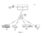
- FIG. 1 is a diagram of an exemplary target detection environment
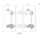
- FIG. 2 is a diagram of another exemplary target detection environment
- FIG. 3 is a block diagram of an exemplary target detection system
- FIG. 4A is a chart illustrating an exemplary clutter Doppler spectrum at various radar platform velocities
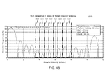
- FIG. 4B is a chart illustrating an exemplary target detection Doppler velocities
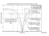
- FIGS. 5A-5C are charts illustrating exemplary radar signals
- FIG. 6 is a flowchart of an exemplary target detection process
- FIG. 7 is a flowchart of another exemplary target detection process.
- the target detection method and apparatus includes technology that, generally, detects targets from a slow moving or stationary radar platform (e.g., water based platform, tracked vehicle based platform, etc.).
- the technology utilizes an explicit model of ground clutter power to detect targets, thereby increasing the likelihood of accurate target detection and decreasing the minimal detection velocity (MDV).
- the technology can detect targets from the slow moving radar platform that has, for example, a small translational velocity (e.g., 1 meter per second, 5 meters per second, 20 meters per second, etc.) and/or can detect target objects that have, for example, a small Doppler velocity (e.g., 0.2 meters per second, 0.5 meters per second, etc.).
- FIG. 1 is a diagram of an exemplary target detection environment 100.
- the environment 100 includes a target detection system 110 and a radar platform 120.
- a radar operator 115 tracks a plurality of target objects utilizing the system 110.
- the plurality of target objects includes a tank 132, a car 134, a tanker trailer 136, and a truck 138.
- the radar platform 120 transmits electromagnetic waves (e.g., high range resolution radar, synthetic aperture radar, etc.) at the target object and receives reflections of the electromagnetic waves from the target object.
- the radar platform 120 communicates data (e.g., radar signal, radar information, etc.) from the reflections of the electromagnetic waves to the target detection system 110.
- the target detection system 110 determines a clutter power (e.g., value of the power reflected from the ground-based objects, expected value of the power reflected from the ground-based objects, etc.) based on the received data (e.g., radar platform velocity, radar beam angle, etc.).
- the target detection system 110 determines a plurality of maximum likelihoods from the radar signal within a plurality of substantially equally spaced frequencies and based on the clutter power.
- the target detection system 110 determines a maximum threshold from the plurality of maximum likelihoods and based on the clutter power.
- the target detection system 110 detects the target based on the maximum threshold and a target detection threshold.
- Table 1 illustrates exemplary maximum clutter powers and data (in this example, radar platform velocity and radar beam angle), as illustrated in FIG. 4A .
- Table 1. Exemplary Clutter Power Signal Identifier Radar Platform Velocity Radar Beam Angle Maximum Clutter Power A23 5 meters per second 0.2 degrees 38 dB A24 10 meters per second 0.2 degrees 39 dB A25 20 meters per second 0.2 degrees 34 dB
- Table 2 illustrates exemplary maximum likclihoods within substantially equally spaced frequencies, as illustrated in FIG. 4B .
- Table 2 illustrates exemplary maximum likclihoods within substantially equally spaced frequencies, as illustrated in FIG. 4B .
- Table 2. Exemplary Maximum Likelihoods Likelihood Identifier Start End Maximum Likelihood 432 3.8 m/s 4.1 m/s 14 dB 434 4.1 m/s 4.4 m/s 7 dB 436 4.4 m/s 4.7 m/s 16 dB 438 4.7 m/s 5.0 m/s 15 dB
- the target detection system 110 determines a maximum threshold from the plurality of maximum likelihoods, as illustrated in Table 1, and based on the clutter power (in this example, the maximum likelihood is 39 dB for the likelihood identifier A24).
- the target detection system 110 detects the target based on the maximum threshold (in this example, 30 dB) and a target detection threshold (e.g., 5 dB, 42 dB, etc.).
- Table 3 illustrates exemplary maximum thresholds and target detection thresholds, as illustrated in FIG. 5A . Table 3.
- Threshold Detection at signal/noise ratio 20dB Target Detection Threshold Variable Target Detection Threshold Target Detection 520a 0.67 m/s 0 dB 12 dB Yes above 0.67 m/s 530a 0.41 m/s 0 dB 12 dB Yes above 0.41 m/s 540a 0.27 m/s 0 dB 12 dB Yes above 0.27 m/s
- FIG. 2 is a diagram of another exemplary target detection environment 200.
- the target environment 200 illustrates target detection at two time frames A 210a and B 210b.
- a radar platform 212 and a tank 214 are at a first position (e.g., the physical location of the radar platform 212 is in square 3x4 and the physical location of the tank 214 is in square 3x8).
- the radar platform 212 and the tank 214 are at a second position (e.g., the physical location of the radar platform 212 is in square 3x5 and the physical location of the tank 214 is in square 9x8).
- the radar platform 212 moved from the first position to the second position at a velocity V r 222 and the tank 214 moved from the first position to the second position at a velocity V t 224.
- the radar platform has a translational velocity (in this example, V r ) of substantially 1 to 20 meters per second.
- V r translational velocity
- the received radar signal includes reflections from a target object and the target object (in this example, the tank) has a velocity of substantially 0.2 to 5.0 meters per second (in this example, V t ).
- FIG. 3 is a diagram of an exemplary target detection system 310.
- the target detection system 310 includes a transceiver 311, a radar power determination module 312, a maximum likelihood determination module 313, a maximum threshold determination module 314, a target detection module 315, a radar signal processor 316, an input device 391, an output device 392, a display device 393, a processor 394, a communication module 395, and a storage device 396.
- the modules and devices described herein can, for example, utilize the processor 394 to execute computer executable instructions and/or include a processor to execute computer executable instructions (e.g., an encryption processing unit, a field programmable gate array processing unit, etc.).
- the target detection system 310 can include, for example, other modules, devices, and/or processors known in the art and/or varieties of the illustrated modules, devices, and/or processors.
- the transceiver 311 receives the radar signal (e.g., from a radar platform, from an intermediate radar signal processing device, etc.).
- the radar power determination module 312 determines a clutter power based on radar information associated with the received radar signal.
- the clutter power includes a clutter Doppler spread.
- the maximum likelihood determination module 313 determines a plurality of maximum likelihoods from the received radar signal within a plurality of substantially equally spaced frequencies and based on the clutter power In some examples, the maximum likelihood determination module 313 determines the plurality of substantially equally spaced frequencies based on the clutter power and the received radar signal. In other examples, the maximum likelihood determination module 313 determines the plurality of maximum likelihoods from the radar signal within a plurality of substantially equally spaced frequencies and based on the clutter power utilizing a fast fourier transform.
- the maximum threshold determination module 314 determines a maximum threshold from the plurality of maximum likelihoods and based on the clutter power. In some examples, the maximum threshold determination module 314 determines the maximum threshold from the plurality of maximum likelihoods and based on the clutter power utilizing Newton's method.
- the target detection module 315 detects the target based on the maximum threshold and a target detection threshold. For example, the target detection module 315 determines if the maximum threshold is above the target detection threshold.
- the radar signal processor 316 determines the radar information based on the radar signal. For example, the radar signal processor 316 extracts the radar angle and the platform speed from the received radar signal.
- the input device 391 receives information associated with the target detection system 310 (e.g., instructions from a user, instructions from another computing device, etc.) from a user (not shown) and/or another computing system (not shown).
- the input device 391 can include, for example, a keyboard, a scanner, etc.
- the output device 392 outputs information associated with the target detection system 310 (e.g., information to a printer (not shown), information to a speaker, etc.).
- the display device 393 displays information associated with the target detection system 310 (e.g., status information, configuration information, etc.).
- the processor 394 executes the operating system and/or any other computer executable instructions for the target detection system 310 (e.g., executes applications, etc.).
- the communication module 395 communicates information to/from the target detection system 310.
- the communication module 395 can receive, for example, information associated with a radar platform.
- the information associated with the radar platform can be associated with a data signal (e.g., data signal from a radar platform, processed data signal from a radar platform, data signal from a motion sensor, data signal from an IFF system, data signal from a global positioning system, data signal from a location system, etc.).
- Each data signal can be associated with a target object (e.g., data signal of a truck by a radar system at time 1.5 seconds, data signal of a truck by a radar system at time 4.5 seconds, etc.).
- a plurality of data signals are associated with the same target object (e.g., the first and the second data signal are associated with a first target object, data signals A-Z are associated with a target object, etc.).
- Table 4 illustrates exemplary data signals. Table 4. Exemplary Data Signals Data Signals Target Object Data Signal Time Range A4 Tank 132 Radar +3.44 seconds 210 meters B9 Tank 132 Radar +3.44 seconds 154 meters C3 Truck 13 8 Motion Sensor A3 +4.32 seconds 94 meters LM Tank 132 Radar +4.52 seconds 342 meters HN Truck 138 Radar +5.34 seconds 453 meters RE Tank 132 Motion Sensor A3 +5.45 seconds 96 meters
- the storage device 396 stores the radar signals (e.g., actual radar signal, processed radar signal, etc.), the target detections, and/or any other data associated with the target detection system 310.
- the storage device 396 can store radar information and/or any other data associated with the target detection system 310.
- the storage device 396 can include a plurality of storage devices and/or the target detection system 310 can include a plurality of storage devices (e g , a ratio storage device, a target profile storage device, etc.).
- the storage device 396 can include, for example, long-term storage (e.g., a hard drive, a tape storage device, flash memory, etc.), short-term storage (e.g., a random access memory, a graphics memory, etc.), and/or any other type of computer readable storage.
- long-term storage e.g., a hard drive, a tape storage device, flash memory, etc.
- short-term storage e.g., a random access memory, a graphics memory, etc.
- any other type of computer readable storage e.g., long-term storage (e.g., a hard drive, a tape storage device, flash memory, etc.), short-term storage (e.g., a random access memory, a graphics memory, etc.), and/or any other type of computer readable storage.
- FIG. 4A is a chart 400a illustrating an exemplary clutter Doppler spectrum at various radar platform velocities.
- the chart 400 illustrates clutter spectral density 410 by Doppler frequency 420.
- FIG. 4B is a chart 400b illustrating an exemplary target detection Doppler velocities. As illustrated in the chart 400b, the target detection Doppler velocities are divided into substantially equaled spaced frequencies 432, 434, 436, 438, 440, 442, 444, and 446.
- FIG. 5A is a chart 500a illustrating an exemplary radar signal for threshold detection.
- the platform (radar) velocity is set at: 5 (540a), 10 (530a) and 20 (520a) m/sec.
- MDV minimum detection value
- FIG. 5B is a chart 500b illustrating an exemplary radar signal across various radar platform velocities (in this example, 1 meters/second, 5 meters/second, 10 meters/second, and 20 meters/second).
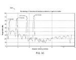
- FIG. 5C is a chart 500c illustrating exemplary radar signals across multiple scatters in ground clutter.
- FIG. 6 is a flowchart 600 of an exemplary target detection process utilizing, for example, the target detection system 310 of FIG. 3 .
- the transceiver 311 receives (610) one or more radar signals.
- the radar signal processor 316 determines (620) the radar information based on the received radar signal.
- the radar power determination module 312 determines (630) a clutter power based on radar information associated with the received radar signal.
- the maximum likelihood determination module 313 determines (640) a plurality of maximum likelihoods from the radar signal within a plurality of substantially equally spaced frequencies and based on the clutter power.
- the maximum threshold determination module 314 determines (650) a maximum threshold from the plurality of maximum likelihoods and based on the clutter power.
- the target detection module 315 detects (660) the target based on the maximum threshold and a target detection threshold.
- the maximum likelihood determination module 313 determines the plurality of maximum likelihoods from the received radar signal within the plurality of substantially equally spaced frequencies and based on the clutter power utilizing a fast fourier transform.
- the radar information includes radar bandwidth, antenna bandwidth, radar platform velocity, and/or antenna angle.
- the clutter power includes a clutter Doppler spread.
- the clutter power is indicative of a distribution of clutter power density.
- Doppler phase steering vector c clutter vector
- f frequency
- u electronic noise vector
- Ae j ⁇ Complex envelope of target
- T inter-pulse period.
- the detection of the target is calculated in accordance with equation: Max f x ⁇ * ⁇ Q - 1 ⁇ e ⁇ f 2 e ⁇ ⁇ f * ⁇ Q - 1 ⁇ e ⁇ f ⁇ Target Detection Threshold
- the MDV for multiple target scatters is modeled utilizing the following steps:
- the MDV for multiple target scatters is modeled using an estimation of the linear prediction coefficients by an iterated quadratic maximum likelihood (IQML) technique in accordance with the following equations and steps:
- C ⁇ ⁇ ⁇ - 1 0 ;
- a F C (1: 2N - L + 1,1: L ) (forward data matrix)
- b B C( 1: 2N- L +1, L +1) (forward data vector)
- a B C ( 2N- L + 2 : 4N- 2L + 2,1: L ) (backward data matrix)
- b B C (2 N- L + 2 : 4 N - 2 L + 2, L + 1) (backward data vector)
- FIG. 7 is a flowchart 700 of another exemplary target detection process utilizing, for example, the target detection system 110 of FIG. 1 .
- the target detection system 110 receives a radar data signal and computes (710) a target Doppler phase steering vector, e ⁇ f D , and substantially equally spaced frequencies within the received radar data signal (e.g., within ⁇ 0.5%, within ⁇ 0.0001%, etc.).
- the target detection system 110 receives (720) a data vector and splits the data vector into substantially equally spaced frequencies.
- the target detection system 110 determines (730) a plurality of maximum likelihoods from the received radar signal within the substantially equally spaced frequencies and based on the clutter power (also referred to as a course search).
- the target detection system 110 determines (740) a maximum threshold from the plurality of maximum likelihoods and based on the clutter power (also referred to as a fine search).
- the target detection system 110 normalizes (750) the maximum threshold and detects (760) the target based on the maximum threshold and a target detection threshold.
- the above-described systems and methods can be implemented in digital electronic circuitry, in computer hardware, firmware, and/or software.
- the implementation can be as a computer program product.
- the implementation can, for example, be in a machine-readable storage device, for execution by, or to control the operation of, data processing apparatus.
- the implementation can, for example, be a programmable processor, a computer, and/or multiple computers.
- a computer program can be written in any form of programming language, including compiled and/or interpreted languages, and the computer program can be deployed in any form, including as a stand-alone program or as a subroutine, element, and/or other unit suitable for use in a computing environment.
- a computer program can be deployed to be executed on one computer or on multiple computers at one site.
- Method steps can be performed by one or more programmable processors executing a computer program to perform functions of the invention by operating on input data and generating output. Method steps can also be performed by and an apparatus can be implemented as special purpose logic circuitry.
- the circuitry can, for example, be a FPGA (field programmable gate array) and/or an ASIC (application-specific integrated circuit).
- Subroutines and software agents can refer to portions of the computer program, the processor, the special circuitry, software, and/or hardware that implement that functionality.
- processors suitable for the execution of a computer program include, by way of example, both general and special purpose microprocessors, and any one or more processors of any kind of digital computer.
- a processor receives instructions and data from a read-only memory or a random access memory or both.
- the essential elements of a computer are a processor for executing instructions and one or more memory devices for storing instructions and data.
- a computer can be operatively coupled to receive data from and/or transfer data to one or more mass storage devices for storing data (e.g., magnetic, magneto-optical disks, or optical disks).
- Computer program products suitable for embodying computer program instructions and data include all forms of non-volatile memory, including by way of example semiconductor memory devices.
- the computer program products can, for example, be EPROM, EEPROM, flash memory devices, magnetic disks, internal hard disks, removable disks, magneto-optical disks, CD-ROM, and/or DVD-ROM disks.
- the processor and the memory can be supplemented by, and/or incorporated in special purpose logic circuitry.
- the above described techniques can be implemented on a computer having a display device.
- the display device can, for example, be a cathode ray tube (CRT) and/or a liquid crystal display (LCD) monitor.
- CTR cathode ray tube
- LCD liquid crystal display
- the interaction with a user can, for example, be a display of information to the user and a keyboard and a pointing device (e.g., a mouse or a trackball) by which the user can provide input to the computer (e.g., interact with a user interface element).
- Other kinds of devices can be used to provide for interaction with a user.
- Other devices can, for example, be feedback provided to the user in any form of sensory feedback (e.g., visual feedback, auditory feedback, or tactile feedback).
- Input from the user can, for example, be received in any form, including acoustic, speech, and/or tactile input.
- the above described techniques can be implemented in a distributed computing system that includes a back-end component.
- the back-end component can, for example, be a data server, a middleware component, and/or an application server.
- the above described techniques can be implemented in a distributing computing system that includes a front-end component.
- the front-end component can, for example, be a client computer having a graphical user interface, a Web browser through which a user can interact with an example implementation, and/or other graphical user interfaces for a transmitting device.
- the components of the system can be interconnected by any form or medium of digital data communication (e.g., a communication network). Examples of communication networks include a local area network (LAN), a wide area network (WAN), the Internet, wired networks, and/or wireless networks.
- LAN local area network
- WAN wide area network
- the Internet wired networks, and/or wireless networks.
- the system can include clients and servers.
- a client and a server are generally remote from each other and typically interact through a communication network.
- the relationship of client and server arises by virtue of computer programs running on the respective computers and having a client-server relationship to each other.
- Packet-based networks can include, for example, the Internet, a carrier internet protocol (TP) network (e.g., local area network (LAN), wide area network (WAN), campus area network (CAN), metropolitan area network (MAN), home area network (HAN)), a private IP network, an IP private branch exchange (IPBX), a wireless network (e.g., radio access network (RAN), 802.11 network, 802.16 network, general packet radio service (GPRS) network, HiperLAN), and/or other packet-based networks.
- TP carrier internet protocol
- LAN local area network
- WAN wide area network
- CAN campus area network
- MAN metropolitan area network
- HAN home area network
- IP network IP private branch exchange
- wireless network e.g., radio access network (RAN), 802.11 network, 802.16 network, general packet radio service (GPRS) network, HiperLAN
- GPRS general packet radio service
- HiperLAN HiperLAN
- Circuit-based networks can include, for example, the public switched telephone network (PSTN), a private branch exchange (PBX), a wireless network (e.g., RAN, bluetooth, code-division multiple access (CDMA) network, time division multiple access (TDMA) network, global system for mobile communications (GSM) network), and/or other circuit-based networks.
- PSTN public switched telephone network
- PBX private branch exchange
- CDMA code-division multiple access
- TDMA time division multiple access
- GSM global system for mobile communications
- the transmitting device can include, for example, a computer, a computer with a browser device, a telephone, an IP phone, a mobile device (e.g., cellular phone, personal digital assistant (PDA) device, laptop computer, electronic mail device), and/or other communication devices.
- the browser device includes, for example, a computer (e.g., desktop computer, laptop computer) with a world wide web browser (e.g., Microsoft® Internet Explorer® available from Microsoft Corporation, Mozilla® Firefox available from Mozilla Corporation).
- the mobile computing device includes, for example, a Blackberry®.
- Comprise, include, and/or plural forms of each are open ended and include the listed parts and can include additional parts that are not listed. And/or is open ended and includes one or more of the listed parts and combinations of the listed parts.
Landscapes
- Engineering & Computer Science (AREA)
- Remote Sensing (AREA)
- Radar, Positioning & Navigation (AREA)
- Physics & Mathematics (AREA)
- Computer Networks & Wireless Communication (AREA)
- General Physics & Mathematics (AREA)
- Electromagnetism (AREA)
- Radar Systems Or Details Thereof (AREA)
Abstract
Description
- The invention was supported, in whole or in part, by a grant HR0011-09-C-0036 from United States Department of Defense. The Government has certain rights in the invention.
- Target detection from a slow moving radar platform can be challenging, if not impossible, due to the Doppler extent of the clutter produced by the radar platform motion. In this regard, when the radar platform is moving slowly and the dwell duration is small, the target detection is limited by the Doppler resolution of the dwell. Prior attempts at target detection utilized Doppler filtering to isolate the target from ground clutter. However, the minimal detection velocity is generally not small enough to effectively and accurately detect targets utilizing Doppler filtering. Thus, a need exists in the art for improved target detection from a slow moving radar platform.
- One approach to target detection is a system. The system includes a radar power determination module configured to determine a clutter power based on radar information associated with a radar signal. The system further includes a maximum likelihood determination module configured to determine a plurality of maximum likelihoods from the radar signal within a plurality of substantially equally spaced frequencies and based on the clutter power. The system further includes a maximum threshold determination module configured to determine a maximum threshold from the plurality of maximum likelihoods and based on the clutter power. The system further includes a target detection module configured to detect the target based on the maximum threshold and a target detection threshold.
- Another approach to target detection is a system. The system includes a means for determining a clutter power based on radar information associated with a radar signal. The system further includes a means for determining a plurality of maximum likelihoods from the radar signal within a plurality of substantially equally spaced frequencies and based on the clutter power. The system further includes a means for determining a maximum threshold from the plurality of maximum likelihoods and based on the clutter power. The system further includes a means for detecting the target based on the maximum threshold and a target detection threshold.
- Another approach to target detection is a method. The method includes determining a clutter power based on radar information associated with a radar signal. The method further includes detecting the target based on a maximum threshold and a target detection threshold. The method further includes determining a plurality of maximum likelihoods from the radar signal within a plurality of substantially equally spaced frequencies and based on the clutter power. The method further includes determining the maximum threshold from the plurality of maximum likelihoods and based on the clutter power.
- Another approach to target detection is a computer program product. The computer program product is tangibly embodied in an information carrier. The computer program product includes instructions being operable to cause a data processing apparatus to determine a clutter power based on radar information associated with a radar signal. The computer program product further includes instructions being operable to cause a data processing apparatus to detect the target based on a maximum threshold and a target detection threshold. The computer program product further includes instructions being operable to cause a data processing apparatus to determine a plurality of maximum likelihoods from the radar signal within a plurality of substantially equally spaced frequencies and based on the clutter power. The computer program product further includes instructions being operable to cause a data processing apparatus to determine the maximum threshold from the plurality of maximum likelihoods and based on the clutter power.
- In other examples, any of the approaches above can include one or more of the following features.
- In some examples, the system further includes a transceiver configured to receive the radar signal.
- In other examples, the system further includes a radar signal processor configured to determine the radar information based on the radar signal.
- In some examples, the system has a translational velocity of substantially 1 to 20 meters per second.
- In other examples, the radar signal includes reflections from a target object and the target object has a Doppler velocity of substantially 0.2 to 1.0 meters per second.
- In some examples, the maximum likelihood determination module is further configured to determine the plurality of substantially equally spaced frequencies based on the clutter power and the radio signal.
- In other examples, the clutter power includes clutter Doppler spread.
- In some examples, the maximum likelihood determination module is further configured to determine the plurality of maximum likelihoods from the radar signal within a plurality of substantially equally spaced frequencies and based on the clutter power utilizing a fast fourier transform.
- In other examples, the maximum threshold determination module is further configured to determine the maximum threshold from the plurality of maximum likelihoods and based on the clutter power utilizing Newton's method.
- In some examples, the radar information includes radar bandwidth, antenna bandwidth, radar platform velocity, and/or antenna angle.
- In other examples, the clutter power includes clutter Doppler spread.
- In some examples, the clutter power is indicative of a distribution of clutter power density.
- In other examples, the determined clutter power spectral density is calculated in accordance with equation:

wherein : - Pc = Clutter Power,
- f = frequency,
- BWC = Doppler bandwidth of clutter =

- Δθc = peak - to - null antenna beamwidth/3 - dB beamwidth,
- ν r = radar platform velocity,
- α = 3/2, and
- θ = angle of antenna boresight to platform velocity.
- In some examples, the method further includes determining the plurality of maximum likelihoods from the radar signal within the plurality of substantially equally spaced frequencies and based on the clutter power utilizing a fast fourier transform.
- In other examples, the determined maximum threshold is calculated in accordance with equation:

wherein (x ) is calculated in accordance with equation:
wherein:
c = clutter vector,u = electronic noise vector, and
Ae jφ = Complex envelope of target; and
wherein H(fk ) is calculated in accordance with equation:
wherein :
wherein (Q) is calculated in accordance with equation:


- In some examples, the detection of the target is calculated in accordance with equation:

- In other examples, the radar signal is defined by (x) in accordance with equation:

wherein : - n = -N,...,0,..., N radar pulses,
- Ae jφ = Complex envelope of target,
- fD = Target Doppler Frequency,
- cn = Clutter return samples,
- un = Electronic noise samples, and
- T = inter-pulse period.
- In some examples, the radar signal comprising a plurality of target Doppler frequencies, wherein the radar signal is defined by (x) in accordance with equation:

wherein : - n =-N,...,0,...,N radar pulses,
- Ae jφ = Complex envelope of target,
- ∫D = Target Doppler Frequency,
- cn = Clutter return samples,
- un = Electronic noise samples,
- m = Number of Target Doppler Frequencies, and
- T = inter-pulse period;
- The target detection techniques described herein can provide one or more of the following advantages. An advantage to the target detection utilizing a maximum likelihood technique is that minimum detection velocity is improved by as much as a factor of three over conventional Doppler filtering with a smaller computational load factor, thereby increasing the speed to detect a target while decreasing the required computing resources needed for such target detection. Another advantage to the target detection is the maximum likelihood detection utilizing the clutter power associated with the radar signal can be explicitly modeled, thereby increasing the likelihood of accurate target detection while increasing the efficiency of the target detection process due to the explicit clutter power calculations.
- The foregoing and other objects, features and advantages will be apparent from the following more particular description of the embodiments, as illustrated in the accompanying drawings in which like reference characters refer to the same parts throughout the different views. The drawings are not necessarily to scale, emphasis instead being placed upon illustrating the principles of the embodiments.
-
FIG. 1 is a diagram of an exemplary target detection environment; -
FIG. 2 is a diagram of another exemplary target detection environment, -
FIG. 3 is a block diagram of an exemplary target detection system; -
FIG. 4A is a chart illustrating an exemplary clutter Doppler spectrum at various radar platform velocities; -
FIG. 4B is a chart illustrating an exemplary target detection Doppler velocities; -
FIGS. 5A-5C are charts illustrating exemplary radar signals; -
FIG. 6 is a flowchart of an exemplary target detection process; and -
FIG. 7 is a flowchart of another exemplary target detection process. - The target detection method and apparatus includes technology that, generally, detects targets from a slow moving or stationary radar platform (e.g., water based platform, tracked vehicle based platform, etc.). The technology utilizes an explicit model of ground clutter power to detect targets, thereby increasing the likelihood of accurate target detection and decreasing the minimal detection velocity (MDV). The technology can detect targets from the slow moving radar platform that has, for example, a small translational velocity (e.g., 1 meter per second, 5 meters per second, 20 meters per second, etc.) and/or can detect target objects that have, for example, a small Doppler velocity (e.g., 0.2 meters per second, 0.5 meters per second, etc.).
-
FIG. 1 is a diagram of an exemplarytarget detection environment 100. Theenvironment 100 includes atarget detection system 110 and aradar platform 120. Aradar operator 115 tracks a plurality of target objects utilizing thesystem 110. The plurality of target objects includes atank 132, acar 134, atanker trailer 136, and atruck 138. Theradar platform 120 transmits electromagnetic waves (e.g., high range resolution radar, synthetic aperture radar, etc.) at the target object and receives reflections of the electromagnetic waves from the target object. Theradar platform 120 communicates data (e.g., radar signal, radar information, etc.) from the reflections of the electromagnetic waves to thetarget detection system 110. - The
target detection system 110 determines a clutter power (e.g., value of the power reflected from the ground-based objects, expected value of the power reflected from the ground-based objects, etc.) based on the received data (e.g., radar platform velocity, radar beam angle, etc.). Thetarget detection system 110 determines a plurality of maximum likelihoods from the radar signal within a plurality of substantially equally spaced frequencies and based on the clutter power. Thetarget detection system 110 determines a maximum threshold from the plurality of maximum likelihoods and based on the clutter power. Thetarget detection system 110 detects the target based on the maximum threshold and a target detection threshold. - Table 1 illustrates exemplary maximum clutter powers and data (in this example, radar platform velocity and radar beam angle), as illustrated in
FIG. 4A .Table 1. Exemplary Clutter Power Signal Identifier Radar Platform Velocity Radar Beam Angle Maximum Clutter Power A23 5 meters per second 0.2 degrees 38 dB A24 10 meters per second 0.2 degrees 39 dB A25 20 meters per second 0.2 degrees 34 dB - Table 2 illustrates exemplary maximum likclihoods within substantially equally spaced frequencies, as illustrated in
FIG. 4B .Table 2. Exemplary Maximum Likelihoods Likelihood Identifier Start End Maximum Likelihood 432 3.8 m/s 4.1 m/s 14 dB 434 4.1 m/s 4.4 m/s 7 dB 436 4.4 m/s 4.7 m/s 16 dB 438 4.7 m/s 5.0 m/s 15 dB - The
target detection system 110 determines a maximum threshold from the plurality of maximum likelihoods, as illustrated in Table 1, and based on the clutter power (in this example, the maximum likelihood is 39 dB for the likelihood identifier A24). Thetarget detection system 110 detects the target based on the maximum threshold (in this example, 30 dB) and a target detection threshold (e.g., 5 dB, 42 dB, etc.). Table 3 illustrates exemplary maximum thresholds and target detection thresholds, as illustrated inFIG. 5A .Table 3. Exemplary Maximum Thresholds and Target Detection Thresholds Detection Identifier Threshold Detection at signal/noise ratio = 20dB Target Detection Threshold Variable Target Detection Threshold Target Detection 520a 0.67 m/s 0 dB 12 dB Yes above 0.67 m/s 530a 0.41 m/s 0 dB 12 dB Yes above 0.41 m/s 540a 0.27 m/s 0 dB 12 dB Yes above 0.27 m/s -
FIG. 2 is a diagram of another exemplarytarget detection environment 200. Thetarget environment 200 illustrates target detection at two time frames A 210a andB 210b. Attime A 210a, aradar platform 212 and atank 214 are at a first position (e.g., the physical location of theradar platform 212 is in square 3x4 and the physical location of thetank 214 is in square 3x8). Attime B 210b, theradar platform 212 and thetank 214 are at a second position (e.g., the physical location of theradar platform 212 is in square 3x5 and the physical location of thetank 214 is in square 9x8). During the time period betweentime A 210a andtime B 210b, theradar platform 212 moved from the first position to the second position at avelocity V r 222 and thetank 214 moved from the first position to the second position at avelocity V t 224. - In some examples, the radar platform has a translational velocity (in this example, Vr) of substantially 1 to 20 meters per second. In other examples, the received radar signal includes reflections from a target object and the target object (in this example, the tank) has a velocity of substantially 0.2 to 5.0 meters per second (in this example, Vt).
-
FIG. 3 is a diagram of an exemplarytarget detection system 310. Thetarget detection system 310 includes atransceiver 311, a radarpower determination module 312, a maximum likelihood determination module 313, a maximum threshold determination module 314, atarget detection module 315, aradar signal processor 316, aninput device 391, anoutput device 392, adisplay device 393, aprocessor 394, acommunication module 395, and astorage device 396. The modules and devices described herein can, for example, utilize theprocessor 394 to execute computer executable instructions and/or include a processor to execute computer executable instructions (e.g., an encryption processing unit, a field programmable gate array processing unit, etc.). It should be understood that thetarget detection system 310 can include, for example, other modules, devices, and/or processors known in the art and/or varieties of the illustrated modules, devices, and/or processors. - The
transceiver 311 receives the radar signal (e.g., from a radar platform, from an intermediate radar signal processing device, etc.). The radarpower determination module 312 determines a clutter power based on radar information associated with the received radar signal. In some examples, the clutter power includes a clutter Doppler spread. - The maximum likelihood determination module 313 determines a plurality of maximum likelihoods from the received radar signal within a plurality of substantially equally spaced frequencies and based on the clutter power In some examples, the maximum likelihood determination module 313 determines the plurality of substantially equally spaced frequencies based on the clutter power and the received radar signal. In other examples, the maximum likelihood determination module 313 determines the plurality of maximum likelihoods from the radar signal within a plurality of substantially equally spaced frequencies and based on the clutter power utilizing a fast fourier transform.
- The maximum threshold determination module 314 determines a maximum threshold from the plurality of maximum likelihoods and based on the clutter power. In some examples, the maximum threshold determination module 314 determines the maximum threshold from the plurality of maximum likelihoods and based on the clutter power utilizing Newton's method.
- The
target detection module 315 detects the target based on the maximum threshold and a target detection threshold. For example, thetarget detection module 315 determines if the maximum threshold is above the target detection threshold. Theradar signal processor 316 determines the radar information based on the radar signal. For example, theradar signal processor 316 extracts the radar angle and the platform speed from the received radar signal. - The
input device 391 receives information associated with the target detection system 310 (e.g., instructions from a user, instructions from another computing device, etc.) from a user (not shown) and/or another computing system (not shown). Theinput device 391 can include, for example, a keyboard, a scanner, etc. Theoutput device 392 outputs information associated with the target detection system 310 (e.g., information to a printer (not shown), information to a speaker, etc.). - The
display device 393 displays information associated with the target detection system 310 (e.g., status information, configuration information, etc.). Theprocessor 394 executes the operating system and/or any other computer executable instructions for the target detection system 310 (e.g., executes applications, etc.). - The
communication module 395 communicates information to/from thetarget detection system 310. Thecommunication module 395 can receive, for example, information associated with a radar platform. The information associated with the radar platform can be associated with a data signal (e.g., data signal from a radar platform, processed data signal from a radar platform, data signal from a motion sensor, data signal from an IFF system, data signal from a global positioning system, data signal from a location system, etc.). Each data signal can be associated with a target object (e.g., data signal of a truck by a radar system at time 1.5 seconds, data signal of a truck by a radar system at time 4.5 seconds, etc.). In some examples, a plurality of data signals are associated with the same target object (e.g., the first and the second data signal are
associated with a first target object, data signals A-Z are associated with a target object, etc.). Table 4 illustrates exemplary data signals.Table 4. Exemplary Data Signals Data Signals Target Object Data Signal Time Range A4 Tank 132 Radar +3.44 seconds 210 meters B9 Tank 132 Radar +3.44 seconds 154 meters C3 Truck 13 8 Motion Sensor A3 +4.32 seconds 94 meters LM Tank 132 Radar +4.52 seconds 342 meters HN Truck 138 Radar +5.34 seconds 453 meters RE Tank 132 Motion Sensor A3 +5.45 seconds 96 meters - The
storage device 396 stores the radar signals (e.g., actual radar signal, processed radar signal, etc.), the target detections, and/or any other data associated with thetarget detection system 310. Thestorage device 396 can store radar information and/or any other data associated with thetarget detection system 310. Thestorage device 396 can include a plurality of storage devices and/or thetarget detection system 310 can include a plurality of storage devices (e g , a ratio storage device, a target profile storage device, etc.). Thestorage device 396 can include, for example, long-term storage (e.g., a hard drive, a tape storage device, flash memory, etc.), short-term storage (e.g., a random access memory, a graphics memory, etc.), and/or any other type of computer readable storage. -
FIG. 4A is achart 400a illustrating an exemplary clutter Doppler spectrum at various radar platform velocities. The chart 400 illustrates clutterspectral density 410 byDoppler frequency 420. -
FIG. 4B is achart 400b illustrating an exemplary target detection Doppler velocities. As illustrated in thechart 400b, the target detection Doppler velocities are divided into substantially equaled spacedfrequencies -
FIG. 5A is a chart 500a illustrating an exemplary radar signal for threshold detection.FIG. 5A illustrates the minimum detection threshold for a scenario where the clutter/noise ratio (CNR) = 40 dB, signal/noise ratio (SNR) = 20 dB, dwell length = 22 msec. the platform (radar) velocity is set at: 5 (540a), 10 (530a) and 20 (520a) m/sec. For each platform velocity the minimum detection value (MDV) (510a) is obtained at the point where the clutter processing filter is 12 dB above the expected average power of the clutter filter (550a) when only clutter and thermal noise are present. -
FIG. 5B is achart 500b illustrating an exemplary radar signal across various radar platform velocities (in this example, 1 meters/second, 5 meters/second, 10 meters/second, and 20 meters/second).FIG. 5B illustrates the Doppler velocity accuracy of an optimal target detector for various target SNRs, platform velocities = 1, 5, 10 and 20 m/sec, target velocity = 0.5 m/sec and clutter-to-noise ratio - 30 dB. -
FIG. 5C is achart 500c illustrating exemplary radar signals across multiple scatters in ground clutter.FIG. 5C illustrates scatterers at: 0.5, 1.8, 3.6 and 4.8 m/sec with CNR = 40 dB; SNR = 20 dB; dwell coherent processing interval (CPI) = 22 ms; and platform velocity = 5 m/sec. -
FIG. 6 is a flowchart 600 of an exemplary target detection process utilizing, for example, thetarget detection system 310 ofFIG. 3 . Thetransceiver 311 receives (610) one or more radar signals. Theradar signal processor 316 determines (620) the radar information based on the received radar signal. The radarpower determination module 312 determines (630) a clutter power based on radar information associated with the received radar signal. The maximum likelihood determination module 313 determines (640) a plurality of maximum likelihoods from the radar signal within a plurality of substantially equally spaced frequencies and based on the clutter power. The maximum threshold determination module 314 determines (650) a maximum threshold from the plurality of maximum likelihoods and based on the clutter power. Thetarget detection module 315 detects (660) the target based on the maximum threshold and a target detection threshold. - In some examples, the maximum likelihood determination module 313 determines the plurality of maximum likelihoods from the received radar signal within the plurality of substantially equally spaced frequencies and based on the clutter power utilizing a fast fourier transform.
- In some examples, the radar information includes radar bandwidth, antenna bandwidth, radar platform velocity, and/or antenna angle. In other examples, the clutter power includes a clutter Doppler spread. In some examples, the clutter power is indicative of a distribution of clutter power density.
- In other examples, the determined clutter power Doppler spectral density is calculated in accordance with equation:

wherein : - Pc = Clutter Power,
- f = frequency,
- BWC = Doppler bandwidth of
clutter 
- ΔθC = peak - to - null antenna beamwidth/3 - dB beamwidth,
- ν r = radar platform velocity,
- α = 3/2, and
- θ = angle of antenna boresight to platform velocity.
- In some examples, the determined maximum threshold is calculated in accordance with equation:

wherein (x ) is calculated in accordance with equation:
wherein:
c = clutter vector, f = frequency,u = electronic noise vector, and Ae jφ = Complex envelope of target; and T = inter-pulse period.
wherein H(fk )is calculated in accordance with equation:
wherein :
wherein (Q) is calculated in accordance with equation:





- In other examples, the detection of the target is calculated in accordance with equation:

- In some examples, the radar signal is defined by (x) in accordance with equation:

wherein: - n = -N,...,0,..., N radar pulses,
- Ae jφ = Complex envelope of target,
- fD = Target Doppler Frequency,
- cn = Clutter return samples
- un = Electronic noise samples, and
- T = inter-pulse period.
- In other examples, the radar signal includes a plurality of target Doppler frequencies and the radar signal is defined by (x) in accordance with equation:

wherein : - n =-N,...,0,...,N radar pulses,
- Ae jφ = Complex envelope of target,
- fD = Target Doppler Frequency,
- cn = Clutter return samples,
- un = Electronic noise samples,
- m = Number of Target Doppler Frequencies, and
- T = inter-pulse period;
- In some examples, the minimum detection value (MDV) (also referred to as the target detection threshold) is defined in accordance with equation:

wherein: - n = -N ,...,0,..., N radar pulses,
- Ae jφ = Complex envelope of target,
- fD = Target Doppler Frequency,
- cn = Clutter return samples,
- un = Electronic noise samples,
- m = Number of Target Doppler Frequencies, and
- T = inter - pulse period;
- Denote the Cholesky decomposition of Q by
- Q=R*R
- In other examples, the MDV for multiple target scatters is modeled utilizing the following steps:
- 1. Form Forward - Backward data Matrix of dimension: 2(2N / 3 + 1) × (4N / 3 + 1)

- 2. Compute the singular value decomposition of CFB : CFB = UΣV*
- 3. Compute the median of slowest 2/3 of the singular values of CFB : µ σ
- 4. Define a threshold : thr = 10 dB/ 20 µσ ; dB = [13-15]
- 5. Find the number of singular values above thr : Lthr = #{σm > thr}
- 6. Use L as the target scatterer model order
- In some examples, the MDV for multiple target scatters is modeled using an estimation of the linear prediction coefficients by an iterated quadratic maximum likelihood (IQML) technique in accordance with the following equations and steps:

where
α = [α 1 α 2 ... αL ] T = vector of linear prediction coefficient The MLE ofa is obtained from by solving fora from
where

JN is a reflection matrix of size NxN.
Define the forward and backward data matrices and data vectors by AF = C(1: 2N - L + 1,1: L) (forward data matrix)b B = C(1: 2N- L+1,L +1) (forward data vector) AB = C(2N- L+ 2 : 4N-2L + 2,1:L) (backward data matrix)b B = C(2N- L + 2 : 4N - 2L + 2, L + 1) (backward data vector)
Start an iteration for the linear prediction vectora 
Until iteration converges, i.e., stops changing or exceeds 20 iterations


Form the linear prediction coefficient polynomial
and find the Doppler frequency fk of the detected scatterers from the roots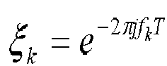


Solve for the complex envelope vector z by
Scatterers are detected if their corresponding envelope is at
least 12 dB above noise in the integrated sense -
FIG. 7 is aflowchart 700 of another exemplary target detection process utilizing, for example, thetarget detection system 110 ofFIG. 1 . Thetarget detection system 110 receives a radar data signal and computes (710) a target Doppler phase steering vector,
target detection system 110 receives (720) a data vector and splits the data vector into substantially equally spaced frequencies. Thetarget detection system 110 determines (730) a plurality of maximum likelihoods from the received radar signal within the substantially equally spaced frequencies and based on the clutter power (also referred to as a course search). Thetarget detection system 110 determines (740) a maximum threshold from the plurality of maximum likelihoods and based on the clutter power (also referred to as a fine search). Thetarget detection system 110 normalizes (750) the maximum threshold and detects (760) the target based on the maximum threshold and a target detection threshold. - The above-described systems and methods can be implemented in digital electronic circuitry, in computer hardware, firmware, and/or software. The implementation can be as a computer program product. The implementation can, for example, be in a machine-readable storage device, for execution by, or to control the operation of, data processing apparatus. The implementation can, for example, be a programmable processor, a computer, and/or multiple computers.
- A computer program can be written in any form of programming language, including compiled and/or interpreted languages, and the computer program can be deployed in any form, including as a stand-alone program or as a subroutine, element, and/or other unit suitable for use in a computing environment. A computer program can be deployed to be executed on one computer or on multiple computers at one site.
- Method steps can be performed by one or more programmable processors executing a computer program to perform functions of the invention by operating on input data and generating output. Method steps can also be performed by and an apparatus can be implemented as special purpose logic circuitry. The circuitry can, for example, be a FPGA (field programmable gate array) and/or an ASIC (application-specific integrated circuit). Subroutines and software agents can refer to portions of the computer program, the processor, the special circuitry, software, and/or hardware that implement that functionality.
- Processors suitable for the execution of a computer program include, by way of example, both general and special purpose microprocessors, and any one or more processors of any kind of digital computer. Generally, a processor receives instructions and data from a read-only memory or a random access memory or both. The essential elements of a computer are a processor for executing instructions and one or more memory devices for storing instructions and data. Generally, a computer can be operatively coupled to receive data from and/or transfer data to one or more mass storage devices for storing data (e.g., magnetic, magneto-optical disks, or optical disks).
- Data transmission and instructions can also occur over a communications network. Computer program products suitable for embodying computer program instructions and data include all forms of non-volatile memory, including by way of example semiconductor memory devices. The computer program products can, for example, be EPROM, EEPROM, flash memory devices, magnetic disks, internal hard disks, removable disks, magneto-optical disks, CD-ROM, and/or DVD-ROM disks. The processor and the memory can be supplemented by, and/or incorporated in special purpose logic circuitry.
- To provide for interaction with a user, the above described techniques can be implemented on a computer having a display device. The display device can, for example, be a cathode ray tube (CRT) and/or a liquid crystal display (LCD) monitor. The interaction with a user can, for example, be a display of information to the user and a keyboard and a pointing device (e.g., a mouse or a trackball) by which the user can provide input to the computer (e.g., interact with a user interface element). Other kinds of devices can be used to provide for interaction with a user. Other devices can, for example, be feedback provided to the user in any form of sensory feedback (e.g., visual feedback, auditory feedback, or tactile feedback). Input from the user can, for example, be received in any form, including acoustic, speech, and/or tactile input.
- The above described techniques can be implemented in a distributed computing system that includes a back-end component. The back-end component can, for example, be a data server, a middleware component, and/or an application server. The above described techniques can be implemented in a distributing computing system that includes a front-end component. The front-end component can, for example, be a client computer having a graphical user interface, a Web browser through which a user can interact with an example implementation, and/or other graphical user interfaces for a transmitting device. The components of the system can be interconnected by any form or medium of digital data communication (e.g., a communication network). Examples of communication networks include a local area network (LAN), a wide area network (WAN), the Internet, wired networks, and/or wireless networks.
- The system can include clients and servers. A client and a server are generally remote from each other and typically interact through a communication network. The relationship of client and server arises by virtue of computer programs running on the respective computers and having a client-server relationship to each other.
- Packet-based networks can include, for example, the Internet, a carrier internet protocol (TP) network (e.g., local area network (LAN), wide area network (WAN), campus area network (CAN), metropolitan area network (MAN), home area network (HAN)), a private IP network, an IP private branch exchange (IPBX), a wireless network (e.g., radio access network (RAN), 802.11 network, 802.16 network, general packet radio service (GPRS) network, HiperLAN), and/or other packet-based networks. Circuit-based networks can include, for example, the public switched telephone network (PSTN), a private branch exchange (PBX), a wireless network (e.g., RAN, bluetooth, code-division multiple access (CDMA) network, time division multiple access (TDMA) network, global system for mobile communications (GSM) network), and/or other circuit-based networks.
- The transmitting device can include, for example, a computer, a computer with a browser device, a telephone, an IP phone, a mobile device (e.g., cellular phone, personal digital assistant (PDA) device, laptop computer, electronic mail device), and/or other communication devices. The browser device includes, for example, a computer (e.g., desktop computer, laptop computer) with a world wide web browser (e.g., Microsoft® Internet Explorer® available from Microsoft Corporation, Mozilla® Firefox available from Mozilla Corporation). The mobile computing device includes, for example, a Blackberry®.
- Comprise, include, and/or plural forms of each are open ended and include the listed parts and can include additional parts that are not listed. And/or is open ended and includes one or more of the listed parts and combinations of the listed parts.
- One skilled in the art will realize the invention may be embodied in other specific forms without departing from the spirit or essential characteristics thereof. The foregoing embodiments are therefore to be considered in all respects illustrative rather than limiting of the invention described herein. Scope of the invention is thus indicated by the appended claims, rather than by the foregoing description, and all changes that come within the meaning and range of equivalency of the claims are therefore intended to be embraced therein.

wherein (f1 ) ... (fm ) are defined in accordance with equation:


wherein (f1 ) and (f2 ) are defined in accordance with equation:


Claims (15)
- A system for detecting a target, the system comprising:means for determining a clutter power based on radar information associated with a radar signal;means for determining a plurality of maximum likelihoods from the radar signal within a plurality of substantially equally spaced frequencies and based on the clutter power;means for determining a maximum threshold from the plurality of maximum likelihoods and based on the clutter power; andmeans for detecting the target based on the maximum threshold and a target detection threshold.
- The system of claim 1, wherein the means for determining clutter power comprises a radar power determination module, the means for determining a plurality of maximum likelihoods comprises a maximum likelihood determination module, the means for determining a maximum threshold comprises a maximum threshold determination module, and the means for detecting the target comprises a target detection module.
- The system of claim 1 or 2, the system further comprising:a transceiver configured to receive the radar signal; and a radar signal processor configured to determine the radar information based on the radar signal, and/or optionally, wherein the system has a translational velocity of substantially 1 to 20 meters per second, and/or optionally, wherein the radar signal comprises reflections from a target object and wherein the target object has a Doppler velocity of substantially 0.2 to 5.0 meters per second.
- The system of any preceding claim, wherein the clutter power comprising clutter Doppler spread.
- The system of any of claims 2 to 4, wherein the maximum likelihood determination module further configured to determine the plurality of substantially equally spaced frequencies based on the clutter power and the radio signal, and/or optionally, wherein the maximum likelihood determination module further configured to determine the plurality of maximum likelihoods from the radar signal within a plurality of substantially equally spaced frequencies and based on the clutter power utilizing a fast fourier transform.
- The system of any of claims 2 to 5, wherein the maximum threshold determination module further configured to determine the maximum threshold from the plurality of maximum likelihoods and based on the clutter power utilizing Newton's method.
- A method for detecting a target, the method comprising:determining a clutter power based on radar information associated with a radar signal; anddetecting the target based on a maximum threshold and a target detection threshold, wherein the detecting comprising:determining a plurality of maximum likelihoods from the radar signal within a plurality of substantially equally spaced frequencies and based on the clutter power, anddetermining the maximum threshold from the plurality of maximum likelihoods and based on the clutter power.
- The method of claim 7, wherein the radar information comprising radar bandwidth, antenna bandwidth, radar platform velocity, antenna angle, or any combination thereof, or optionally, wherein the clutter power comprising clutter Doppler spread, or optionally, wherein the clutter power is indicative of a distribution of clutter power density.
- The method of claim 7 or 8, wherein the determined clutter power is calculated in accordance with equation:

wherein :Pc = Clutter Power,f = frequency,BWc = Doppler bandwidth of clutter Δθ c = peak - to - null antenna beamwidth/3 - dB beamwidth,ν r = radar platform velocity,α = 3 / 2, andθ = angle of antenna boresight to platform velocity.
 - The method of any of claims 7 to 9, wherein the determining the plurality of maximum likelihoods from the radar signal within the plurality of substantially equally spaced frequencies and based on the clutter power further comprising determining the plurality of maximum likelihoods from the radar signal within the plurality of substantially equally spaced frequencies and based on the clutter power utilizing a fast fourier transform.
- The method of any of claims 7 to 10, wherein the determined maximum threshold is calculated in accordance with equation:

wherein (x ) is calculated in accordance with equation:
wherein:
c = clutter vector,f = frequency,u = electronic noise vector, andAe jφ = Complex envelope of target; andT = inter-pulse period.wherein H (fk ) is calculated in accordance with equation:
wherein :


- The method of claim 11, wherein the detection of the target is calculated in accordance with equation:

- The method of claim 7, wherein the radar signal is defined by (x) in accordance with equation:

wherein:n = -N,...,0,..., N radar pulses,Ae jφ = Complex envelope of target,fD = Target Doppler Frequency,cn = Clutter return samples,un = Electronic noise samples, andT = inter-pulse period. - The method of any of claims 7 to 13, wherein the radar signal comprising a plurality of target Doppler frequencies, wherein the radar signal is defined by (x) in accordance with equation:

wherein:n = -N,...,0,..., N radar pulses,Ae jφ = Complex envelope of target,fD = Target Doppler Frequency,cn = Clutter return samples,un = Electronicnoise samples,m = Number of Target Doppler Frequencies, andT = inter-pulse period;wherein (e ) is defined in accordance with equation:
wherein (f1 ) and (f2 ) are defined in accordance with equation:
- A computer program product operable to cause a data processing apparatus to implement the method steps of any of claim 7 to 14.
Applications Claiming Priority (1)
| Application Number | Priority Date | Filing Date | Title |
|---|---|---|---|
| US12/887,047 US8237605B2 (en) | 2010-09-21 | 2010-09-21 | Target detection from a slow moving radar platform |
Publications (1)
| Publication Number | Publication Date |
|---|---|
| EP2431763A1 true EP2431763A1 (en) | 2012-03-21 |
Family
ID=45406901
Family Applications (1)
| Application Number | Title | Priority Date | Filing Date |
|---|---|---|---|
| EP11170747A Withdrawn EP2431763A1 (en) | 2010-09-21 | 2011-06-21 | Target detection from a slow moving radar platform |
Country Status (3)
| Country | Link |
|---|---|
| US (1) | US8237605B2 (en) |
| EP (1) | EP2431763A1 (en) |
| IL (1) | IL213719A0 (en) |
Families Citing this family (7)
| Publication number | Priority date | Publication date | Assignee | Title |
|---|---|---|---|---|
| US8917199B2 (en) * | 2011-04-13 | 2014-12-23 | Raytheon Company | Subterranean image generating device and associated method |
| US8912951B2 (en) * | 2012-10-09 | 2014-12-16 | Raytheon Company | Moving target detection using a two-dimensional folding approach |
| US9720072B2 (en) * | 2014-08-28 | 2017-08-01 | Waymo Llc | Methods and systems for vehicle radar coordination and interference reduction |
| KR102644368B1 (en) * | 2018-09-06 | 2024-03-07 | 현대자동차주식회사 | Method and device for correcting target angle error of ladar sensor |
| CN110598271B (en) * | 2019-08-22 | 2023-06-20 | 中国电子科技集团公司第二十九研究所 | System and method for realizing 4-auxiliary antenna SLC function based on FPGA |
| US11740328B2 (en) * | 2020-12-16 | 2023-08-29 | DC-001, Inc. | Methods and systems for processing radar signals |
| CN115856816A (en) * | 2022-11-23 | 2023-03-28 | 电子科技大学长三角研究院(湖州) | FDA radar stationary target detection method and system based on transmit power allocation |
Citations (4)
| Publication number | Priority date | Publication date | Assignee | Title |
|---|---|---|---|---|
| US5818383A (en) * | 1981-11-27 | 1998-10-06 | Northrop Grumman Corporation | Interferometric moving vehicle imaging apparatus and method |
| WO2002037137A1 (en) * | 2000-11-02 | 2002-05-10 | Totalförsvarets Forskningsinstitut | A synthetic aperture radar system capable of detecting moving targets |
| US6911933B1 (en) * | 2004-05-14 | 2005-06-28 | The United States Of America As Represented By The Secretary Of The Air Force | Dynamic logic algorithm used for detecting slow-moving or concealed targets in synthetic aperture radar (SAR) images |
| US7064702B1 (en) * | 2005-03-01 | 2006-06-20 | The Boeing Company | System, method and computer program product for reducing quadratic phase errors in synthetic aperture radar signals |
Family Cites Families (16)
| Publication number | Priority date | Publication date | Assignee | Title |
|---|---|---|---|---|
| US4210911A (en) | 1977-12-19 | 1980-07-01 | Westinghouse Electric Corp. | Method for decreasing minimum observable velocity of moving targets |
| US5559518A (en) | 1981-11-27 | 1996-09-24 | Northrop Grumman Corporation | Low target velocity interferometric AMTI radar |
| US6809681B1 (en) | 1992-08-25 | 2004-10-26 | Raytheon Company | Random-modulation radar signal-induced interference cancellation method and apparatus |
| US5784026A (en) | 1996-09-23 | 1998-07-21 | Raytheon E-Systems, Inc. | Radar detection of accelerating airborne targets |
| US6400306B1 (en) | 1999-12-17 | 2002-06-04 | Sicom Systems, Ltd | Multi-channel moving target radar detection and imaging apparatus and method |
| US6633253B2 (en) | 2001-04-02 | 2003-10-14 | Thomas J. Cataldo | Dual synthetic aperture radar system |
| US7109911B1 (en) | 2002-04-01 | 2006-09-19 | Cataldo Thomas J | Dual synthetic aperture radar system |
| US6756935B1 (en) | 2003-01-31 | 2004-06-29 | The Boeing Company | Full polarization ground moving target indicator radar automatic target detection algorithm |
| US7193558B1 (en) | 2003-09-03 | 2007-03-20 | The United States Of America As Represented By The Secretary Of The Navy | Radar processor system and method |
| US7038618B2 (en) | 2004-04-26 | 2006-05-02 | Budic Robert D | Method and apparatus for performing bistatic radar functions |
| US7106243B2 (en) | 2004-11-23 | 2006-09-12 | Raytheon Company | Technique for enhanced quality high resolution 2D imaging of ground moving targets |
| US7286079B2 (en) | 2005-04-21 | 2007-10-23 | The United States Of America As Represented By The Secretary Of The Navy | Method and apparatus for detecting slow-moving targets in high-resolution sea clutter |
| US7576682B1 (en) * | 2006-03-14 | 2009-08-18 | Lockheed Martin Corporation | Method and system for radar target detection and angle estimation in the presence of jamming |
| GB0701869D0 (en) | 2007-01-31 | 2007-03-14 | Cambridge Consultants | Adaptive radar |
| US7652614B2 (en) | 2007-07-30 | 2010-01-26 | Colorado State University Research Foundation | Ground clutter mitigation using a parametric time domain method |
| US7830299B2 (en) | 2007-11-28 | 2010-11-09 | Lockheed Martin Corporation | Radar system for manmade device detection and discrimination from clutter |
-
2010
- 2010-09-21 US US12/887,047 patent/US8237605B2/en active Active
-
2011
- 2011-06-21 EP EP11170747A patent/EP2431763A1/en not_active Withdrawn
- 2011-06-22 IL IL213719A patent/IL213719A0/en unknown
Patent Citations (4)
| Publication number | Priority date | Publication date | Assignee | Title |
|---|---|---|---|---|
| US5818383A (en) * | 1981-11-27 | 1998-10-06 | Northrop Grumman Corporation | Interferometric moving vehicle imaging apparatus and method |
| WO2002037137A1 (en) * | 2000-11-02 | 2002-05-10 | Totalförsvarets Forskningsinstitut | A synthetic aperture radar system capable of detecting moving targets |
| US6911933B1 (en) * | 2004-05-14 | 2005-06-28 | The United States Of America As Represented By The Secretary Of The Air Force | Dynamic logic algorithm used for detecting slow-moving or concealed targets in synthetic aperture radar (SAR) images |
| US7064702B1 (en) * | 2005-03-01 | 2006-06-20 | The Boeing Company | System, method and computer program product for reducing quadratic phase errors in synthetic aperture radar signals |
Non-Patent Citations (1)
| Title |
|---|
| ABATZOGLOU T J ET AL: "Range, radial velocity, and acceleration MLE using radar LFM pulse train", IEEE TRANSACTIONS ON AEROSPACE AND ELECTRONIC SYSTEMS IEEE USA, vol. 34, no. 4, October 1998 (1998-10-01), pages 1070 - 1083, XP002666847, ISSN: 0018-9251 * |
Also Published As
| Publication number | Publication date |
|---|---|
| IL213719A0 (en) | 2011-11-30 |
| US20120068881A1 (en) | 2012-03-22 |
| US8237605B2 (en) | 2012-08-07 |
Similar Documents
| Publication | Publication Date | Title |
|---|---|---|
| US8237605B2 (en) | Target detection from a slow moving radar platform | |
| CN108089171B (en) | A kind of radar rapid detection method for unmanned plane target | |
| US8344942B2 (en) | System and method for resolving ambiguity in radar, lidar, and acoustic systems | |
| US7212149B2 (en) | System, method and computer program product for detecting and tracking a moving ground target having a single phase center antenna | |
| CN105717480B (en) | The passive method for rapidly positioning in list station based on phase difference | |
| CN101408616A (en) | Inverse synthetic aperture radar imaging distance aligning method applicable to low signal-noise ratio data | |
| CN110554391B (en) | Low-altitude wind shear wind speed estimation method based on DDD-GMB | |
| CN113009473A (en) | Multi-beam staring radar low-elevation target height measurement method, device and medium | |
| CN110133654A (en) | A moving target detection method for high-orbit satellite SAR | |
| CN102288949A (en) | Optimal processor based maneuvering target detection method | |
| Xiong et al. | Radar high-speed target coherent detection method based on modified radon inverse Fourier transform | |
| Liu et al. | An effective space-borne ISAR high-resolution imaging approach for satellite on-orbit based on minimum entropy optimization | |
| Ding et al. | A novel iterative inner-pulse integration target detection method for bistatic radar | |
| CN105717479A (en) | Single-station passive quick positioning method based on fractional order Fourier transformation | |
| Awadhiya et al. | Analyzing the effective coherent integration time for space surveillance radar processing | |
| CN106772373A (en) | For the SAR imaging methods of any ground moving object | |
| Imanifar et al. | A Noniterative Map-Drift Autofocus Algorithm Using PCA for RDA-Based Stripmap SAR Imaging | |
| JP7200570B2 (en) | SIGNAL PROCESSING DEVICE, SIGNAL PROCESSING METHOD AND CONTROL PROGRAM | |
| Qiu et al. | Focusing bistaitc images use RDA based on hyperbolic approximating | |
| Han et al. | Generalized pseudopolar format algorithm for radar imaging with highly suboptimal aperture length | |
| US9041598B2 (en) | Non Doppler-tolerant pulse compression in radar systems | |
| CN115790607B (en) | Non-cooperative target maneuvering characteristic detection method based on short arc historical data | |
| Björk | Adaptive clutter suppression in airborne surveillance radar | |
| Zheng et al. | An analysis on error sources of guidance radar detection performance | |
| Cai et al. | Dual‐channel particle filter based track‐before‐detect for monopulse radar |
Legal Events
| Date | Code | Title | Description |
|---|---|---|---|
| PUAI | Public reference made under article 153(3) epc to a published international application that has entered the european phase |
Free format text: ORIGINAL CODE: 0009012 |
|
| AK | Designated contracting states |
Kind code of ref document: A1 Designated state(s): AL AT BE BG CH CY CZ DE DK EE ES FI FR GB GR HR HU IE IS IT LI LT LU LV MC MK MT NL NO PL PT RO RS SE SI SK SM TR |
|
| AX | Request for extension of the european patent |
Extension state: BA ME |
|
| 17P | Request for examination filed |
Effective date: 20120606 |
|
| 17Q | First examination report despatched |
Effective date: 20130624 |
|
| GRAP | Despatch of communication of intention to grant a patent |
Free format text: ORIGINAL CODE: EPIDOSNIGR1 |
|
| INTG | Intention to grant announced |
Effective date: 20140912 |
|
| STAA | Information on the status of an ep patent application or granted ep patent |
Free format text: STATUS: THE APPLICATION IS DEEMED TO BE WITHDRAWN |
|
| 18D | Application deemed to be withdrawn |
Effective date: 20150123 |