EP2431619A1 - System for the detachable connection of thick parts - Google Patents
System for the detachable connection of thick parts Download PDFInfo
- Publication number
- EP2431619A1 EP2431619A1 EP10774581A EP10774581A EP2431619A1 EP 2431619 A1 EP2431619 A1 EP 2431619A1 EP 10774581 A EP10774581 A EP 10774581A EP 10774581 A EP10774581 A EP 10774581A EP 2431619 A1 EP2431619 A1 EP 2431619A1
- Authority
- EP
- European Patent Office
- Prior art keywords
- bolt
- piece
- threaded
- join
- elastic washer
- Prior art date
- Legal status (The legal status is an assumption and is not a legal conclusion. Google has not performed a legal analysis and makes no representation as to the accuracy of the status listed.)
- Granted
Links
- 230000008878 coupling Effects 0.000 claims description 5
- 238000010168 coupling process Methods 0.000 claims description 5
- 238000005859 coupling reaction Methods 0.000 claims description 5
- 230000003100 immobilizing effect Effects 0.000 abstract description 2
- 239000000463 material Substances 0.000 description 3
- 238000006243 chemical reaction Methods 0.000 description 2
- 230000006866 deterioration Effects 0.000 description 1
- 238000005553 drilling Methods 0.000 description 1
- 230000000694 effects Effects 0.000 description 1
- 238000010348 incorporation Methods 0.000 description 1
- 239000007769 metal material Substances 0.000 description 1
- 238000000034 method Methods 0.000 description 1
- 230000036316 preload Effects 0.000 description 1
- 230000002265 prevention Effects 0.000 description 1
- 230000000284 resting effect Effects 0.000 description 1
Images


Classifications
-
- F—MECHANICAL ENGINEERING; LIGHTING; HEATING; WEAPONS; BLASTING
- F16—ENGINEERING ELEMENTS AND UNITS; GENERAL MEASURES FOR PRODUCING AND MAINTAINING EFFECTIVE FUNCTIONING OF MACHINES OR INSTALLATIONS; THERMAL INSULATION IN GENERAL
- F16B—DEVICES FOR FASTENING OR SECURING CONSTRUCTIONAL ELEMENTS OR MACHINE PARTS TOGETHER, e.g. NAILS, BOLTS, CIRCLIPS, CLAMPS, CLIPS OR WEDGES; JOINTS OR JOINTING
- F16B5/00—Joining sheets or plates, e.g. panels, to one another or to strips or bars parallel to them
- F16B5/02—Joining sheets or plates, e.g. panels, to one another or to strips or bars parallel to them by means of fastening members using screw-thread
- F16B5/0275—Joining sheets or plates, e.g. panels, to one another or to strips or bars parallel to them by means of fastening members using screw-thread the screw-threaded element having at least two axially separated threaded portions
-
- F—MECHANICAL ENGINEERING; LIGHTING; HEATING; WEAPONS; BLASTING
- F16—ENGINEERING ELEMENTS AND UNITS; GENERAL MEASURES FOR PRODUCING AND MAINTAINING EFFECTIVE FUNCTIONING OF MACHINES OR INSTALLATIONS; THERMAL INSULATION IN GENERAL
- F16B—DEVICES FOR FASTENING OR SECURING CONSTRUCTIONAL ELEMENTS OR MACHINE PARTS TOGETHER, e.g. NAILS, BOLTS, CIRCLIPS, CLAMPS, CLIPS OR WEDGES; JOINTS OR JOINTING
- F16B5/00—Joining sheets or plates, e.g. panels, to one another or to strips or bars parallel to them
- F16B5/02—Joining sheets or plates, e.g. panels, to one another or to strips or bars parallel to them by means of fastening members using screw-thread
- F16B5/0216—Joining sheets or plates, e.g. panels, to one another or to strips or bars parallel to them by means of fastening members using screw-thread the position of the plates to be connected being adjustable
- F16B5/0233—Joining sheets or plates, e.g. panels, to one another or to strips or bars parallel to them by means of fastening members using screw-thread the position of the plates to be connected being adjustable allowing for adjustment perpendicular to the plane of the plates
-
- F—MECHANICAL ENGINEERING; LIGHTING; HEATING; WEAPONS; BLASTING
- F16—ENGINEERING ELEMENTS AND UNITS; GENERAL MEASURES FOR PRODUCING AND MAINTAINING EFFECTIVE FUNCTIONING OF MACHINES OR INSTALLATIONS; THERMAL INSULATION IN GENERAL
- F16B—DEVICES FOR FASTENING OR SECURING CONSTRUCTIONAL ELEMENTS OR MACHINE PARTS TOGETHER, e.g. NAILS, BOLTS, CIRCLIPS, CLAMPS, CLIPS OR WEDGES; JOINTS OR JOINTING
- F16B35/00—Screw-bolts; Stay-bolts; Screw-threaded studs; Screws; Set screws
- F16B35/04—Screw-bolts; Stay-bolts; Screw-threaded studs; Screws; Set screws with specially-shaped head or shaft in order to fix the bolt on or in an object
-
- F—MECHANICAL ENGINEERING; LIGHTING; HEATING; WEAPONS; BLASTING
- F16—ENGINEERING ELEMENTS AND UNITS; GENERAL MEASURES FOR PRODUCING AND MAINTAINING EFFECTIVE FUNCTIONING OF MACHINES OR INSTALLATIONS; THERMAL INSULATION IN GENERAL
- F16B—DEVICES FOR FASTENING OR SECURING CONSTRUCTIONAL ELEMENTS OR MACHINE PARTS TOGETHER, e.g. NAILS, BOLTS, CIRCLIPS, CLAMPS, CLIPS OR WEDGES; JOINTS OR JOINTING
- F16B39/00—Locking of screws, bolts or nuts
- F16B39/22—Locking of screws, bolts or nuts in which the locking takes place during screwing down or tightening
- F16B39/24—Locking of screws, bolts or nuts in which the locking takes place during screwing down or tightening by means of washers, spring washers, or resilient plates that lock against the object
-
- F—MECHANICAL ENGINEERING; LIGHTING; HEATING; WEAPONS; BLASTING
- F16—ENGINEERING ELEMENTS AND UNITS; GENERAL MEASURES FOR PRODUCING AND MAINTAINING EFFECTIVE FUNCTIONING OF MACHINES OR INSTALLATIONS; THERMAL INSULATION IN GENERAL
- F16B—DEVICES FOR FASTENING OR SECURING CONSTRUCTIONAL ELEMENTS OR MACHINE PARTS TOGETHER, e.g. NAILS, BOLTS, CIRCLIPS, CLAMPS, CLIPS OR WEDGES; JOINTS OR JOINTING
- F16B5/00—Joining sheets or plates, e.g. panels, to one another or to strips or bars parallel to them
- F16B5/02—Joining sheets or plates, e.g. panels, to one another or to strips or bars parallel to them by means of fastening members using screw-thread
Definitions
- the present invention relates to a system for the detachable union of large thickness pieces in which one starts with at least two superimposed pieces to be joined which are in contact via one of their faces, in such a way that we just have access to the system of union via one of the free faces of one of the pieces, while via the free face of the other piece of the pair we do not have access to the system of union.
- the object of the invention is to achieve a completely reliable union between the two superimposed pieces in question in order to prevent said pieces from becoming separated in relation to each other, this objective being achieved by means of the characteristic system of union.
- the invention proposes a system for detachable union of large thickness pieces in which one starts with two pieces to join (top and bottom) that are in contact with each other via one of their faces, in such a way that once the union has been made access is had to the system of union via one of the free faces of one of the pieces (upper) while access to said union via the free face of the other piece of the pair (lower) is not possible.
- the system of union starts with a bolt with threaded end segments, one of which is coupled in a threaded blind hole of the lower piece, immobilizing said bolt in that thread thanks to an annular extension incorporated by it and above all thanks to a characteristic elastic washer that is inserted between that annular extension and the inner face of the lower piece, on which inner face the threaded blind hole has been made, said elastic washer being the element that is going to prevent the bolt from coming undone.
- the annular extension separates an upper section from another lower section of the bolt.
- the lower section comprises a narrow segment corresponding to the location of the washer and the threaded segment for being coupled in the blind hole of the lower piece.
- the upper section comprises a length that exceeds the thickness of the upper piece and includes a threaded end segment, in such a way that the end section of the bolt will be housed in a through hole of the upper piece, with the union finally being ensured by means of a self-locking nut coupled in the threaded end of the upper section of the said bolt, and at the same time the said nut will press against the free face of the upper piece, thereby ensuring a stable and secure union between the two pieces.
- the characteristic elastic washer is a somewhat special piece which, once fitted in the inventive system, exerts an additional pressure and thrust in the axial direction between both threaded couplings, in such a way that it counteracts any load or vibration that could cause that bolt to come loose.
- the elastic washer has a certain characteristic geometry and is made of a material that at all times works under an elastic regime (which does not undergo plastic deformations in the range of stresses to which it is going to be subjected). Depending on each case, it can be made of a metal material or even a plastic material.
- the washer in question is placed on top of the part we wish to join and we fit a self-locking nut via the upper threaded segment of the bolt via which we have access, as referred to above.
- the washer in question can be provided with a certain geometry that increases the friction in the zone of union and prevents the bolt from turning.
- This geometry can consist of making the part in contact with the bolt rough in order to increase the resistance to turning, and on the other hand it can consist of creating some notches or teeth in the lugs of the washer that stick into the piece to join and also help to prevent the bolt from turning.
- this method of union also allows us to know in a certain way the tightening torque that we are giving to the bolt when we fit it in the lower piece.
- the washer itself will allow us to control the tightening torque.
- the system for the detachable union of large thickness pieces is intended for joining two pieces, an upper one 1 and another lower one 2 that are in direct contact via their respective inner faces 3 and 4 of those two pieces 1 and 2, in such a way that the inner face 4 of the lower piece 2 contains a blind hole 5, provided with a thread for coupling a first threaded end segment 6 of a bolt 7 with the interposition of a characteristic elastic washer 8 which makes contact against that inner face 4 of the lower piece 2 and also makes contact on an annular extension 9 integral with the bolt itself 7, thereby ensuring the immobilization of the bolt 7 on the lower piece 2.
- the annular extension 9 separates a lower section 10 corresponding to the lower piece 2 and an upper section 11 which corresponds to the upper piece 1.
- the elastic washer 8 is coupled to the bolt 7 in correspondence with a short intermediate segment 12 of the bolt 7 limited between the annular extension 9 and the start of the first threaded end segment 6.
- the upper segment 1 incorporates at least one through hole 13 housing the upper section 11 of the bolt 7, this section incorporating a second threaded end segment 14 of the bolt 7 which projects via the free face of the upper piece 1, with a self-locking nut 15 being coupled in that threaded segment 14 which nut 15 will press against the free face of the upper piece 1, thereby ensuring a correct and immovable union between the two pieces 1 and 2.
- the elastic washer 8 has a characteristic structure that comprises a centered annular body 16 which limits a central hole 17 via which the bolt 7 is introduced along with some inclined radial flaps 18 pointing downwards, with the outermost free ends of said flaps 18 resting on the inner face 4 of the lower piece 2, while the annular extension 9 of the bolt 7 rests on the upper surface of the annular body 16 of the elastic washer 8.
- This upper surface of the washer 8 that is in contact with the annular extension 9 can incorporate a rough surface, defined for example by a profile in the form of a triangular wave 19, thereby achieving a more reliable immobilization of the bolt 7, preventing it from turning in the direction of coming loose.
- the radial flaps 18 can also incorporate some teeth or notches 20 which permit a more reliable grip of the elastic washer 8 on the inner face 4 of the lower piece 2.
- the elastic washer 8 maintains its elasticity and therefore maintains its thrust and pressure in the axial direction in order to ensure the immobilization of the bolt 7 in the event of possible vibrations and other external effects tending to loosen the bolt 7.
- the inner face 3 of the upper piece 1 incorporates a staggered coaxial recess or hollow 21 for permitting the housing of the annular extension 9 and of the elastic washer 8.
Landscapes
- Engineering & Computer Science (AREA)
- General Engineering & Computer Science (AREA)
- Mechanical Engineering (AREA)
- Bolts, Nuts, And Washers (AREA)
- Lining And Supports For Tunnels (AREA)
- Joining Of Building Structures In Genera (AREA)
- Mutual Connection Of Rods And Tubes (AREA)
Abstract
Description
- As stated in the title of this descriptive specification, the present invention relates to a system for the detachable union of large thickness pieces in which one starts with at least two superimposed pieces to be joined which are in contact via one of their faces, in such a way that we just have access to the system of union via one of the free faces of one of the pieces, while via the free face of the other piece of the pair we do not have access to the system of union.
- So, the object of the invention is to achieve a completely reliable union between the two superimposed pieces in question in order to prevent said pieces from becoming separated in relation to each other, this objective being achieved by means of the characteristic system of union.
- It is a safe system that prevents the union from coming loose during its useful life.
- When two or more pieces need to be joined in which no access can be had to the inner part of the assembly to fit, the most usual solution is to use rivets of the kind known as or "blind rivets" or "Jo-bolts", which only require access from one of the pieces to be fitted in order to be able to be installed.
- The problem arises when the pieces to join have a thickness that is too great, since this type of "blind" rivet has a limited length; and when it wished to detach the pieces to join in the future, then the only way to do this is by breaking them or drilling them, which are operations that entail damage and deterioration of the housings for the rivets.
- Moreover, it can be pointed out that there currently exist conical washers for providing permanent stresses in the direction of the tightening screws used in the union between nut and screw with the aim of preventing loss of preload in that union.
- With the aim of achieving the objectives and avoiding the drawbacks mentioned in the above sections, the invention proposes a system for detachable union of large thickness pieces in which one starts with two pieces to join (top and bottom) that are in contact with each other via one of their faces, in such a way that once the union has been made access is had to the system of union via one of the free faces of one of the pieces (upper) while access to said union via the free face of the other piece of the pair (lower) is not possible.
- To achieve this, the system of union starts with a bolt with threaded end segments, one of which is coupled in a threaded blind hole of the lower piece, immobilizing said bolt in that thread thanks to an annular extension incorporated by it and above all thanks to a characteristic elastic washer that is inserted between that annular extension and the inner face of the lower piece, on which inner face the threaded blind hole has been made, said elastic washer being the element that is going to prevent the bolt from coming undone.
- The annular extension separates an upper section from another lower section of the bolt.
- The lower section comprises a narrow segment corresponding to the location of the washer and the threaded segment for being coupled in the blind hole of the lower piece.
- On the other hand, the upper section comprises a length that exceeds the thickness of the upper piece and includes a threaded end segment, in such a way that the end section of the bolt will be housed in a through hole of the upper piece, with the union finally being ensured by means of a self-locking nut coupled in the threaded end of the upper section of the said bolt, and at the same time the said nut will press against the free face of the upper piece, thereby ensuring a stable and secure union between the two pieces.
- Conventionally, once the bolt has been fitted on the lower piece without the incorporation of the characteristic elastic washer, we would then fit the other upper piece securing the assembly with the self-locking nut on the threaded free segment of the bolt, securing just the threaded end of the bolt corresponding to the upper piece, while the threaded union of the bolt on the blind hole of the lower piece would not be secured, so that any vibrations or forces to which the assembly of the two joined pieces is subjected could cause that threaded union of the blind hole to come loose and give rise to maladjustments and slackening, and therefore possible accidents.
- On the other hand, in the invention that we are concerned with, the characteristic elastic washer is a somewhat special piece which, once fitted in the inventive system, exerts an additional pressure and thrust in the axial direction between both threaded couplings, in such a way that it counteracts any load or vibration that could cause that bolt to come loose.
- So, the elastic washer has a certain characteristic geometry and is made of a material that at all times works under an elastic regime (which does not undergo plastic deformations in the range of stresses to which it is going to be subjected). Depending on each case, it can be made of a metal material or even a plastic material.
- Its special geometry will mean that, when the piece is deformed elastically, it will always tend to recover its initial shape by introducing the additional pressure that we seek.
- Depending on the type of union, load or stress, the type of material chosen, etc., one can adjust the angle of opening of some lugs incorporated into the washer, the number of these lugs, their geometry, etc. The fact is that the piece constituting the washer can be deformed and at all times tends to recover its initial shape.
- The tightening of the bolt will deform the special piece constituting the washer and will prevent it from regaining its initial shape. As the special piece constituting the washer is elastic, it will always want to return to its initial position, generating a reaction force on the central part of the bolt which will prevent the latter from coming loose in its coupling in the blind hole.
- Once the washer in question has been fitted, it is placed on top of the part we wish to join and we fit a self-locking nut via the upper threaded segment of the bolt via which we have access, as referred to above.
- Moreover, in cases in which an additional pressure is needed which the deformation itself of the washer is not able to provide us with, the washer in question can be provided with a certain geometry that increases the friction in the zone of union and prevents the bolt from turning.
- This geometry can consist of making the part in contact with the bolt rough in order to increase the resistance to turning, and on the other hand it can consist of creating some notches or teeth in the lugs of the washer that stick into the piece to join and also help to prevent the bolt from turning.
- In this way we could achieve an extra security in the fixing of the bolt, something that we cannot achieve with any conventional conical washer.
- Furthermore, this method of union also allows us to know in a certain way the tightening torque that we are giving to the bolt when we fit it in the lower piece. The washer itself will allow us to control the tightening torque.
- Below, in order to facilitate a better understanding of this descriptive specification and forming an integral part thereof, some figures are attached in which the object of the invention has been represented by way of illustration and non-limiting.
-
-
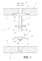
Figure 1 .- Shows an exploded view of the system for the detachable union of large thickness pieces, the inventive object. It incorporates a characteristic piece by way of an elastic washer which, together with a self-locking nut, ensures the immobilization of the system of the invention. -
Figure 2 .- Shows a view in cross-section of the system for the detachable union of the invention in the assembled position. -
Figures 3 and 4 .- Shows some perspective views of the characteristic pieces by way of elastic washers mentioned above. - Considering the numbering adopted in the figures, the system for the detachable union of large thickness pieces is intended for joining two pieces, an upper one 1 and another lower one 2 that are in direct contact via their respective
inner faces pieces inner face 4 of thelower piece 2 contains ablind hole 5, provided with a thread for coupling a first threadedend segment 6 of abolt 7 with the interposition of a characteristicelastic washer 8 which makes contact against thatinner face 4 of thelower piece 2 and also makes contact on anannular extension 9 integral with the bolt itself 7, thereby ensuring the immobilization of thebolt 7 on thelower piece 2. So, theannular extension 9 separates alower section 10 corresponding to thelower piece 2 and anupper section 11 which corresponds to theupper piece 1. - The
elastic washer 8 is coupled to thebolt 7 in correspondence with a shortintermediate segment 12 of thebolt 7 limited between theannular extension 9 and the start of the first threadedend segment 6. - Moreover, the
upper segment 1 incorporates at least one throughhole 13 housing theupper section 11 of thebolt 7, this section incorporating a second threadedend segment 14 of thebolt 7 which projects via the free face of theupper piece 1, with a self-locking nut 15 being coupled in that threadedsegment 14 whichnut 15 will press against the free face of theupper piece 1, thereby ensuring a correct and immovable union between the twopieces - Furthermore, the
elastic washer 8 has a characteristic structure that comprises a centeredannular body 16 which limits acentral hole 17 via which thebolt 7 is introduced along with some inclinedradial flaps 18 pointing downwards, with the outermost free ends of saidflaps 18 resting on theinner face 4 of thelower piece 2, while theannular extension 9 of thebolt 7 rests on the upper surface of theannular body 16 of theelastic washer 8. - This upper surface of the
washer 8 that is in contact with theannular extension 9 can incorporate a rough surface, defined for example by a profile in the form of atriangular wave 19, thereby achieving a more reliable immobilization of thebolt 7, preventing it from turning in the direction of coming loose. - In turn, the
radial flaps 18 can also incorporate some teeth ornotches 20 which permit a more reliable grip of theelastic washer 8 on theinner face 4 of thelower piece 2. - Once the
bolt 7 is immobilized, theelastic washer 8 maintains its elasticity and therefore maintains its thrust and pressure in the axial direction in order to ensure the immobilization of thebolt 7 in the event of possible vibrations and other external effects tending to loosen thebolt 7. - The
inner face 3 of theupper piece 1 incorporates a staggered coaxial recess or hollow 21 for permitting the housing of theannular extension 9 and of theelastic washer 8. - The forces of
action 23 andreaction 22 that are generated between the threads of the threadedend segment 6 of thebolt 7 and the threading of theblind hole 5 due to the axial pressure exerted by theelastic washer 8 ensure the prevention of rotation of thebolt 7 in the direction of coming loose.
Claims (6)
- A DETACHABLE JOINT for coupling large thickness pieces, comprising:a bolt (7) having: a first section with a first threaded end segment; a second section with a second threaded end segment; and an intermediate annular extension between said first and second sections, for limiting the tightening rotation of the bolt;a first piece (2) to join, with a threaded bind hole (5) threadedly connected to the first threaded end segment (6) of the bolt (7);a second piece (1) to join, having: a through hole (13) connected to the second threaded end segment (14) of the bolt (7) in which is coupled a self-locking nut (15); and a coaxial space (21) being defined around the bolt (7) in correspondence with the inner faces of the two pieces to join; andanti-rotation means of the bolt in its threaded coupling in the blind hole (5) of the first piece (2), wherein said means consists of an intermediate piece coupled to the bolt (7) and which is arranged between the annular extension (9) of the bolt (7) and the inner face (4) of the first piece (2).
- THE DETACHABLE JOINT according to claim 1, wherein the intermediate piece is an elastic washer (8) comprising an annular body (16) on one of the faces of which rests the annular extension (9) of the bolt (7), with some inclined radial flaps (18) projecting from the edge of said annular body (16), these flaps (18) seating via their outermost free edges on the inner face of the first piece to join (2).
- THE DETACHABLE JOINT according to claim 2, wherein the contact face of the annular body (16) of the elastic washer (8) incorporates a rough surface with a high degree of friction against the annular extension (9) of the bolt (7).
- THE DETACHABLE JOINT according to claim 3, wherein the rough surface of the contact face of the elastic washer (8) presents a narrow profile in the form of a triangular wave.
- THE DETACHABLE JOINT according to any one of claims 2 to 4, wherein the outermost free edge of the inclined radial flaps (18) incorporates a plurality of teeth-shaped notches (20) with a greater degree of grip and friction on the inner face (4) of the first piece to join (2) which incorporates the blind hole (5).
- THE DETACHABLE JOINT according to any one of preceding claims, wherein between the first threaded segment (6) of the bolt (7) and the annular extension (9) of that same bolt (7) there exists a short intermediate segment that corresponds to the location of the elastic washer (8).
Applications Claiming Priority (2)
| Application Number | Priority Date | Filing Date | Title |
|---|---|---|---|
| ES200930162A ES2350550B1 (en) | 2009-05-13 | 2009-05-13 | REMOVABLE UNION SYSTEM OF LARGE THICK PARTS |
| PCT/ES2010/070172 WO2010130854A1 (en) | 2009-05-13 | 2010-03-24 | System for the detachable connection of thick parts |
Publications (3)
| Publication Number | Publication Date |
|---|---|
| EP2431619A1 true EP2431619A1 (en) | 2012-03-21 |
| EP2431619A4 EP2431619A4 (en) | 2013-12-18 |
| EP2431619B1 EP2431619B1 (en) | 2017-05-03 |
Family
ID=43068617
Family Applications (1)
| Application Number | Title | Priority Date | Filing Date |
|---|---|---|---|
| EP10774581.2A Not-in-force EP2431619B1 (en) | 2009-05-13 | 2010-03-24 | System for the detachable connection of thick parts |
Country Status (6)
| Country | Link |
|---|---|
| US (1) | US20100290862A1 (en) |
| EP (1) | EP2431619B1 (en) |
| CN (1) | CN102422032A (en) |
| ES (1) | ES2350550B1 (en) |
| RU (1) | RU2011150401A (en) |
| WO (1) | WO2010130854A1 (en) |
Cited By (1)
| Publication number | Priority date | Publication date | Assignee | Title |
|---|---|---|---|---|
| WO2023150821A1 (en) * | 2022-02-10 | 2023-08-17 | Alan Strang | A blind mechanical fastening system for connecting members to one another |
Families Citing this family (15)
| Publication number | Priority date | Publication date | Assignee | Title |
|---|---|---|---|---|
| KR101187022B1 (en) | 2012-01-02 | 2012-09-28 | 김승희 | Assembly structure using bolt |
| DE102013008982B4 (en) * | 2013-05-28 | 2016-02-11 | Ibs Filtran Kunststoff-/ Metallerzeugnisse Gmbh | Housing cover, in particular plastic oil pan |
| TWM509280U (en) * | 2015-05-01 | 2015-09-21 | Dtech Prec Ind Co Ltd | Elastic fastening device and its packaging vehicle |
| CN104986344A (en) * | 2015-07-15 | 2015-10-21 | 江西洪都航空工业集团有限责任公司 | Adjustable static pressure sensor installation structure |
| DE102016106152A1 (en) * | 2016-04-05 | 2017-10-05 | Elringklinger Ag | Fastening device for a decoupling device on a shielding part, decoupling device comprising the fastening device and shielding part comprising the decoupling device |
| EP3375946A1 (en) * | 2017-03-17 | 2018-09-19 | Knapp GmbH | Connector for screwing two workpieces at an angle |
| DE102018102124A1 (en) * | 2017-11-24 | 2019-05-29 | Huf Hülsbeck & Fürst Gmbh & Co. Kg | Motor vehicle fastening system for fastening a first motor vehicle component to a second motor vehicle component |
| CN108238297A (en) * | 2018-03-15 | 2018-07-03 | 宁波象吹塑家具有限公司 | Packaging location structure |
| CN108386434A (en) * | 2018-05-09 | 2018-08-10 | 张家港汉升机械科技有限公司 | A kind of screw being easily installed |
| US11313395B2 (en) * | 2018-08-29 | 2022-04-26 | The University Of Toledo | Materials and methods for joining metal sheets |
| CN111237459A (en) * | 2018-11-28 | 2020-06-05 | 青岛海尔智慧厨房电器有限公司 | a gasket |
| CN209569255U (en) * | 2019-01-11 | 2019-11-01 | 瑞典爱立信有限公司 | Stop screw component and fastening structure including the component |
| JP2020159414A (en) * | 2019-03-26 | 2020-10-01 | いすゞ自動車株式会社 | To be fastened |
| CN115020891A (en) * | 2022-06-15 | 2022-09-06 | 中国第一汽车股份有限公司 | Passenger car battery fixed knot constructs and car |
| CN120557545B (en) * | 2025-07-31 | 2025-10-10 | 中太能源科技(上海)有限公司 | Reinforced plywood anchoring structure and method |
Family Cites Families (16)
| Publication number | Priority date | Publication date | Assignee | Title |
|---|---|---|---|---|
| US889593A (en) * | 1907-12-19 | 1908-06-02 | John C Fleischmann | Nut-lock. |
| GB348076A (en) * | 1930-02-06 | 1931-05-06 | Charles Alfred Morton | Screw stud locking device |
| US1911384A (en) * | 1930-07-14 | 1933-05-30 | Shakeproof Lock Washer Co | Lock washer |
| US2537527A (en) * | 1947-05-01 | 1951-01-09 | James H Heckert | Nonloosening safety bolt |
| US2703724A (en) * | 1949-08-11 | 1955-03-08 | Yuen Frank Der | Sectional bamboo building structure with coupling |
| US3897112A (en) * | 1973-01-22 | 1975-07-29 | Dayton Walther Corp | Rim mounting |
| US4304503A (en) * | 1977-09-07 | 1981-12-08 | Semblex Corporation | Opposite threaded stud |
| US4331414A (en) * | 1980-05-12 | 1982-05-25 | Wheatley Jr Thomas | Leakproof stud bolt incorporating modified thread |
| US4690365A (en) * | 1986-05-16 | 1987-09-01 | Grumman Aerospace Corporation | Jack stud |
| US5148720A (en) * | 1991-09-12 | 1992-09-22 | Swenson Sr Roger M | Lock-up solenoid assembly |
| US5913547A (en) * | 1997-07-03 | 1999-06-22 | Muncie Power Products, Inc. | P.T.O. securement method |
| US6024600A (en) * | 1998-03-09 | 2000-02-15 | Lucent Technologies Inc. | Mounting fastener for grounding daisy chain connected building entrance protectors |
| US5967723A (en) * | 1998-07-01 | 1999-10-19 | Avibank Mfg., Inc. | Nut and bolt locking system |
| DE20208960U1 (en) * | 2002-06-10 | 2002-09-19 | Dahlmanns, Kurt, 52538 Gangelt | fixing screw |
| DE102005029529B8 (en) * | 2005-06-25 | 2008-02-21 | Bayerische Motoren Werke Ag | Connecting device for fastening components |
| US7922433B2 (en) * | 2007-06-14 | 2011-04-12 | Pratt & Whitney Rocketdyne, Inc. | Locking fastening apparatus |
-
2009
- 2009-05-13 ES ES200930162A patent/ES2350550B1/en active Active
- 2009-10-28 US US12/607,565 patent/US20100290862A1/en not_active Abandoned
-
2010
- 2010-03-24 RU RU2011150401/02A patent/RU2011150401A/en unknown
- 2010-03-24 EP EP10774581.2A patent/EP2431619B1/en not_active Not-in-force
- 2010-03-24 CN CN2010800210442A patent/CN102422032A/en active Pending
- 2010-03-24 WO PCT/ES2010/070172 patent/WO2010130854A1/en not_active Ceased
Cited By (2)
| Publication number | Priority date | Publication date | Assignee | Title |
|---|---|---|---|---|
| WO2023150821A1 (en) * | 2022-02-10 | 2023-08-17 | Alan Strang | A blind mechanical fastening system for connecting members to one another |
| AU2023218297B2 (en) * | 2022-02-10 | 2024-02-22 | Alan Strang | A blind mechanical fastening system for connecting members to one another |
Also Published As
| Publication number | Publication date |
|---|---|
| WO2010130854A1 (en) | 2010-11-18 |
| US20100290862A1 (en) | 2010-11-18 |
| ES2350550B1 (en) | 2011-11-18 |
| ES2350550A1 (en) | 2011-01-25 |
| CN102422032A (en) | 2012-04-18 |
| EP2431619B1 (en) | 2017-05-03 |
| EP2431619A4 (en) | 2013-12-18 |
| RU2011150401A (en) | 2013-06-20 |
Similar Documents
| Publication | Publication Date | Title |
|---|---|---|
| EP2431619B1 (en) | System for the detachable connection of thick parts | |
| KR100804000B1 (en) | Tolerance Compensation Mounting Device | |
| KR102232065B1 (en) | Locking washer assembly | |
| RU2272186C2 (en) | Locking fastening device | |
| EP1636500B1 (en) | Connector | |
| US9321301B2 (en) | Attachment arrangement for composite wheels | |
| EP3326243B1 (en) | Electrical connector and method for connecting | |
| US20210381555A1 (en) | Flexible coupling | |
| US20190316626A1 (en) | One-piece self-locking nut | |
| JPWO2015118702A1 (en) | Bolt with locking function | |
| CN106286555A (en) | Self locking anti-loose nut | |
| CN104148571A (en) | Blind rivetting system | |
| US3702087A (en) | Double shank bolt | |
| EP2478230B1 (en) | System and method for fixedly connecting sheets | |
| EP2395248B1 (en) | Connecting arrangement and method of fastening a bolt | |
| JP7450634B2 (en) | Bolted joint using a deformable sleeve with longitudinal grooves | |
| RU2463491C2 (en) | Mounting/assembly element to assemble items, in particular, overlapping plates and/or composite elements | |
| CA2967052A1 (en) | One-piece self-locking nut | |
| WO2017020284A1 (en) | Anti-rotation sleeve, fastening connection assembly, fastening connection structure, and installation method | |
| GB2041139A (en) | Locking of nuts | |
| KR100882567B1 (en) | Self-tightening bolt fastening structure | |
| KR102108429B1 (en) | Anti-loosing nut equipped with locking pin and production method therof | |
| EP2395252A1 (en) | Connecting arrangement and method for fastening a bolt | |
| AU2008200632A1 (en) | Locking washer | |
| US10352348B2 (en) | Fastening systems |
Legal Events
| Date | Code | Title | Description |
|---|---|---|---|
| PUAI | Public reference made under article 153(3) epc to a published international application that has entered the european phase |
Free format text: ORIGINAL CODE: 0009012 |
|
| 17P | Request for examination filed |
Effective date: 20111118 |
|
| AK | Designated contracting states |
Kind code of ref document: A1 Designated state(s): AT BE BG CH CY CZ DE DK EE ES FI FR GB GR HR HU IE IS IT LI LT LU LV MC MK MT NL NO PL PT RO SE SI SK SM TR |
|
| DAX | Request for extension of the european patent (deleted) | ||
| REG | Reference to a national code |
Ref country code: DE Ref legal event code: R079 Ref document number: 602010042076 Country of ref document: DE Free format text: PREVIOUS MAIN CLASS: F16B0035040000 Ipc: F16B0005020000 |
|
| A4 | Supplementary search report drawn up and despatched |
Effective date: 20131115 |
|
| RIC1 | Information provided on ipc code assigned before grant |
Ipc: F16B 5/02 20060101AFI20131111BHEP Ipc: F16B 35/04 20060101ALI20131111BHEP Ipc: F16B 39/24 20060101ALI20131111BHEP |
|
| GRAP | Despatch of communication of intention to grant a patent |
Free format text: ORIGINAL CODE: EPIDOSNIGR1 |
|
| RAP1 | Party data changed (applicant data changed or rights of an application transferred) |
Owner name: AIRBUS OPERATIONS, S.L. |
|
| INTG | Intention to grant announced |
Effective date: 20161024 |
|
| GRAS | Grant fee paid |
Free format text: ORIGINAL CODE: EPIDOSNIGR3 |
|
| GRAA | (expected) grant |
Free format text: ORIGINAL CODE: 0009210 |
|
| AK | Designated contracting states |
Kind code of ref document: B1 Designated state(s): AT BE BG CH CY CZ DE DK EE ES FI FR GB GR HR HU IE IS IT LI LT LU LV MC MK MT NL NO PL PT RO SE SI SK SM TR |
|
| REG | Reference to a national code |
Ref country code: GB Ref legal event code: FG4D |
|
| REG | Reference to a national code |
Ref country code: AT Ref legal event code: REF Ref document number: 890321 Country of ref document: AT Kind code of ref document: T Effective date: 20170515 Ref country code: CH Ref legal event code: EP |
|
| REG | Reference to a national code |
Ref country code: IE Ref legal event code: FG4D |
|
| REG | Reference to a national code |
Ref country code: DE Ref legal event code: R096 Ref document number: 602010042076 Country of ref document: DE |
|
| REG | Reference to a national code |
Ref country code: NL Ref legal event code: MP Effective date: 20170503 |
|
| REG | Reference to a national code |
Ref country code: AT Ref legal event code: MK05 Ref document number: 890321 Country of ref document: AT Kind code of ref document: T Effective date: 20170503 |
|
| REG | Reference to a national code |
Ref country code: LT Ref legal event code: MG4D |
|
| PG25 | Lapsed in a contracting state [announced via postgrant information from national office to epo] |
Ref country code: AT Free format text: LAPSE BECAUSE OF FAILURE TO SUBMIT A TRANSLATION OF THE DESCRIPTION OR TO PAY THE FEE WITHIN THE PRESCRIBED TIME-LIMIT Effective date: 20170503 Ref country code: GR Free format text: LAPSE BECAUSE OF FAILURE TO SUBMIT A TRANSLATION OF THE DESCRIPTION OR TO PAY THE FEE WITHIN THE PRESCRIBED TIME-LIMIT Effective date: 20170804 Ref country code: HR Free format text: LAPSE BECAUSE OF FAILURE TO SUBMIT A TRANSLATION OF THE DESCRIPTION OR TO PAY THE FEE WITHIN THE PRESCRIBED TIME-LIMIT Effective date: 20170503 Ref country code: NO Free format text: LAPSE BECAUSE OF FAILURE TO SUBMIT A TRANSLATION OF THE DESCRIPTION OR TO PAY THE FEE WITHIN THE PRESCRIBED TIME-LIMIT Effective date: 20170803 Ref country code: LT Free format text: LAPSE BECAUSE OF FAILURE TO SUBMIT A TRANSLATION OF THE DESCRIPTION OR TO PAY THE FEE WITHIN THE PRESCRIBED TIME-LIMIT Effective date: 20170503 Ref country code: ES Free format text: LAPSE BECAUSE OF FAILURE TO SUBMIT A TRANSLATION OF THE DESCRIPTION OR TO PAY THE FEE WITHIN THE PRESCRIBED TIME-LIMIT Effective date: 20170503 Ref country code: FI Free format text: LAPSE BECAUSE OF FAILURE TO SUBMIT A TRANSLATION OF THE DESCRIPTION OR TO PAY THE FEE WITHIN THE PRESCRIBED TIME-LIMIT Effective date: 20170503 |
|
| PG25 | Lapsed in a contracting state [announced via postgrant information from national office to epo] |
Ref country code: NL Free format text: LAPSE BECAUSE OF FAILURE TO SUBMIT A TRANSLATION OF THE DESCRIPTION OR TO PAY THE FEE WITHIN THE PRESCRIBED TIME-LIMIT Effective date: 20170503 Ref country code: LV Free format text: LAPSE BECAUSE OF FAILURE TO SUBMIT A TRANSLATION OF THE DESCRIPTION OR TO PAY THE FEE WITHIN THE PRESCRIBED TIME-LIMIT Effective date: 20170503 Ref country code: PL Free format text: LAPSE BECAUSE OF FAILURE TO SUBMIT A TRANSLATION OF THE DESCRIPTION OR TO PAY THE FEE WITHIN THE PRESCRIBED TIME-LIMIT Effective date: 20170503 Ref country code: IS Free format text: LAPSE BECAUSE OF FAILURE TO SUBMIT A TRANSLATION OF THE DESCRIPTION OR TO PAY THE FEE WITHIN THE PRESCRIBED TIME-LIMIT Effective date: 20170903 Ref country code: BG Free format text: LAPSE BECAUSE OF FAILURE TO SUBMIT A TRANSLATION OF THE DESCRIPTION OR TO PAY THE FEE WITHIN THE PRESCRIBED TIME-LIMIT Effective date: 20170803 Ref country code: SE Free format text: LAPSE BECAUSE OF FAILURE TO SUBMIT A TRANSLATION OF THE DESCRIPTION OR TO PAY THE FEE WITHIN THE PRESCRIBED TIME-LIMIT Effective date: 20170503 |
|
| PG25 | Lapsed in a contracting state [announced via postgrant information from national office to epo] |
Ref country code: DK Free format text: LAPSE BECAUSE OF FAILURE TO SUBMIT A TRANSLATION OF THE DESCRIPTION OR TO PAY THE FEE WITHIN THE PRESCRIBED TIME-LIMIT Effective date: 20170503 Ref country code: SK Free format text: LAPSE BECAUSE OF FAILURE TO SUBMIT A TRANSLATION OF THE DESCRIPTION OR TO PAY THE FEE WITHIN THE PRESCRIBED TIME-LIMIT Effective date: 20170503 Ref country code: RO Free format text: LAPSE BECAUSE OF FAILURE TO SUBMIT A TRANSLATION OF THE DESCRIPTION OR TO PAY THE FEE WITHIN THE PRESCRIBED TIME-LIMIT Effective date: 20170503 Ref country code: EE Free format text: LAPSE BECAUSE OF FAILURE TO SUBMIT A TRANSLATION OF THE DESCRIPTION OR TO PAY THE FEE WITHIN THE PRESCRIBED TIME-LIMIT Effective date: 20170503 Ref country code: CZ Free format text: LAPSE BECAUSE OF FAILURE TO SUBMIT A TRANSLATION OF THE DESCRIPTION OR TO PAY THE FEE WITHIN THE PRESCRIBED TIME-LIMIT Effective date: 20170503 |
|
| REG | Reference to a national code |
Ref country code: DE Ref legal event code: R097 Ref document number: 602010042076 Country of ref document: DE |
|
| PG25 | Lapsed in a contracting state [announced via postgrant information from national office to epo] |
Ref country code: IT Free format text: LAPSE BECAUSE OF FAILURE TO SUBMIT A TRANSLATION OF THE DESCRIPTION OR TO PAY THE FEE WITHIN THE PRESCRIBED TIME-LIMIT Effective date: 20170503 Ref country code: SM Free format text: LAPSE BECAUSE OF FAILURE TO SUBMIT A TRANSLATION OF THE DESCRIPTION OR TO PAY THE FEE WITHIN THE PRESCRIBED TIME-LIMIT Effective date: 20170503 |
|
| PLBE | No opposition filed within time limit |
Free format text: ORIGINAL CODE: 0009261 |
|
| STAA | Information on the status of an ep patent application or granted ep patent |
Free format text: STATUS: NO OPPOSITION FILED WITHIN TIME LIMIT |
|
| 26N | No opposition filed |
Effective date: 20180206 |
|
| PG25 | Lapsed in a contracting state [announced via postgrant information from national office to epo] |
Ref country code: SI Free format text: LAPSE BECAUSE OF FAILURE TO SUBMIT A TRANSLATION OF THE DESCRIPTION OR TO PAY THE FEE WITHIN THE PRESCRIBED TIME-LIMIT Effective date: 20170503 |
|
| REG | Reference to a national code |
Ref country code: DE Ref legal event code: R119 Ref document number: 602010042076 Country of ref document: DE |
|
| REG | Reference to a national code |
Ref country code: CH Ref legal event code: PL |
|
| GBPC | Gb: european patent ceased through non-payment of renewal fee |
Effective date: 20180324 |
|
| PG25 | Lapsed in a contracting state [announced via postgrant information from national office to epo] |
Ref country code: MC Free format text: LAPSE BECAUSE OF FAILURE TO SUBMIT A TRANSLATION OF THE DESCRIPTION OR TO PAY THE FEE WITHIN THE PRESCRIBED TIME-LIMIT Effective date: 20170503 |
|
| REG | Reference to a national code |
Ref country code: BE Ref legal event code: MM Effective date: 20180331 |
|
| REG | Reference to a national code |
Ref country code: IE Ref legal event code: MM4A |
|
| PG25 | Lapsed in a contracting state [announced via postgrant information from national office to epo] |
Ref country code: LU Free format text: LAPSE BECAUSE OF NON-PAYMENT OF DUE FEES Effective date: 20180324 |
|
| PG25 | Lapsed in a contracting state [announced via postgrant information from national office to epo] |
Ref country code: IE Free format text: LAPSE BECAUSE OF NON-PAYMENT OF DUE FEES Effective date: 20180324 Ref country code: DE Free format text: LAPSE BECAUSE OF NON-PAYMENT OF DUE FEES Effective date: 20181002 |
|
| PG25 | Lapsed in a contracting state [announced via postgrant information from national office to epo] |
Ref country code: GB Free format text: LAPSE BECAUSE OF NON-PAYMENT OF DUE FEES Effective date: 20180324 Ref country code: CH Free format text: LAPSE BECAUSE OF NON-PAYMENT OF DUE FEES Effective date: 20180331 Ref country code: BE Free format text: LAPSE BECAUSE OF NON-PAYMENT OF DUE FEES Effective date: 20180331 Ref country code: LI Free format text: LAPSE BECAUSE OF NON-PAYMENT OF DUE FEES Effective date: 20180331 |
|
| PG25 | Lapsed in a contracting state [announced via postgrant information from national office to epo] |
Ref country code: FR Free format text: LAPSE BECAUSE OF NON-PAYMENT OF DUE FEES Effective date: 20180331 |
|
| PG25 | Lapsed in a contracting state [announced via postgrant information from national office to epo] |
Ref country code: MT Free format text: LAPSE BECAUSE OF NON-PAYMENT OF DUE FEES Effective date: 20180324 |
|
| PG25 | Lapsed in a contracting state [announced via postgrant information from national office to epo] |
Ref country code: TR Free format text: LAPSE BECAUSE OF FAILURE TO SUBMIT A TRANSLATION OF THE DESCRIPTION OR TO PAY THE FEE WITHIN THE PRESCRIBED TIME-LIMIT Effective date: 20170503 |
|
| PG25 | Lapsed in a contracting state [announced via postgrant information from national office to epo] |
Ref country code: PT Free format text: LAPSE BECAUSE OF FAILURE TO SUBMIT A TRANSLATION OF THE DESCRIPTION OR TO PAY THE FEE WITHIN THE PRESCRIBED TIME-LIMIT Effective date: 20170503 Ref country code: HU Free format text: LAPSE BECAUSE OF FAILURE TO SUBMIT A TRANSLATION OF THE DESCRIPTION OR TO PAY THE FEE WITHIN THE PRESCRIBED TIME-LIMIT; INVALID AB INITIO Effective date: 20100324 |
|
| PG25 | Lapsed in a contracting state [announced via postgrant information from national office to epo] |
Ref country code: CY Free format text: LAPSE BECAUSE OF FAILURE TO SUBMIT A TRANSLATION OF THE DESCRIPTION OR TO PAY THE FEE WITHIN THE PRESCRIBED TIME-LIMIT Effective date: 20170503 Ref country code: MK Free format text: LAPSE BECAUSE OF NON-PAYMENT OF DUE FEES Effective date: 20170503 |