EP2431595A1 - Method of estimating a combustion index and/or the indicated torque in a cylinder of a four stroke internal combustion engine with spontaneous mixture ignition - Google Patents
Method of estimating a combustion index and/or the indicated torque in a cylinder of a four stroke internal combustion engine with spontaneous mixture ignition Download PDFInfo
- Publication number
- EP2431595A1 EP2431595A1 EP11181724A EP11181724A EP2431595A1 EP 2431595 A1 EP2431595 A1 EP 2431595A1 EP 11181724 A EP11181724 A EP 11181724A EP 11181724 A EP11181724 A EP 11181724A EP 2431595 A1 EP2431595 A1 EP 2431595A1
- Authority
- EP
- European Patent Office
- Prior art keywords
- ind
- harmonic
- indicated torque
- determining
- torque
- Prior art date
- Legal status (The legal status is an assumption and is not a legal conclusion. Google has not performed a legal analysis and makes no representation as to the accuracy of the status listed.)
- Granted
Links
Images


Classifications
-
- F—MECHANICAL ENGINEERING; LIGHTING; HEATING; WEAPONS; BLASTING
- F02—COMBUSTION ENGINES; HOT-GAS OR COMBUSTION-PRODUCT ENGINE PLANTS
- F02D—CONTROLLING COMBUSTION ENGINES
- F02D41/00—Electrical control of supply of combustible mixture or its constituents
- F02D41/02—Circuit arrangements for generating control signals
- F02D41/14—Introducing closed-loop corrections
- F02D41/1497—With detection of the mechanical response of the engine
-
- F—MECHANICAL ENGINEERING; LIGHTING; HEATING; WEAPONS; BLASTING
- F02—COMBUSTION ENGINES; HOT-GAS OR COMBUSTION-PRODUCT ENGINE PLANTS
- F02D—CONTROLLING COMBUSTION ENGINES
- F02D35/00—Controlling engines, dependent on conditions exterior or interior to engines, not otherwise provided for
- F02D35/02—Controlling engines, dependent on conditions exterior or interior to engines, not otherwise provided for on interior conditions
- F02D35/023—Controlling engines, dependent on conditions exterior or interior to engines, not otherwise provided for on interior conditions by determining the cylinder pressure
-
- F—MECHANICAL ENGINEERING; LIGHTING; HEATING; WEAPONS; BLASTING
- F02—COMBUSTION ENGINES; HOT-GAS OR COMBUSTION-PRODUCT ENGINE PLANTS
- F02D—CONTROLLING COMBUSTION ENGINES
- F02D35/00—Controlling engines, dependent on conditions exterior or interior to engines, not otherwise provided for
- F02D35/02—Controlling engines, dependent on conditions exterior or interior to engines, not otherwise provided for on interior conditions
- F02D35/028—Controlling engines, dependent on conditions exterior or interior to engines, not otherwise provided for on interior conditions by determining the combustion timing or phasing
-
- F—MECHANICAL ENGINEERING; LIGHTING; HEATING; WEAPONS; BLASTING
- F02—COMBUSTION ENGINES; HOT-GAS OR COMBUSTION-PRODUCT ENGINE PLANTS
- F02D—CONTROLLING COMBUSTION ENGINES
- F02D41/00—Electrical control of supply of combustible mixture or its constituents
- F02D41/0097—Electrical control of supply of combustible mixture or its constituents using means for generating speed signals
-
- F—MECHANICAL ENGINEERING; LIGHTING; HEATING; WEAPONS; BLASTING
- F02—COMBUSTION ENGINES; HOT-GAS OR COMBUSTION-PRODUCT ENGINE PLANTS
- F02D—CONTROLLING COMBUSTION ENGINES
- F02D41/00—Electrical control of supply of combustible mixture or its constituents
- F02D41/22—Safety or indicating devices for abnormal conditions
- F02D41/222—Safety or indicating devices for abnormal conditions relating to the failure of sensors or parameter detection devices
-
- F—MECHANICAL ENGINEERING; LIGHTING; HEATING; WEAPONS; BLASTING
- F02—COMBUSTION ENGINES; HOT-GAS OR COMBUSTION-PRODUCT ENGINE PLANTS
- F02D—CONTROLLING COMBUSTION ENGINES
- F02D41/00—Electrical control of supply of combustible mixture or its constituents
- F02D41/02—Circuit arrangements for generating control signals
- F02D41/14—Introducing closed-loop corrections
- F02D41/1401—Introducing closed-loop corrections characterised by the control or regulation method
- F02D2041/1433—Introducing closed-loop corrections characterised by the control or regulation method using a model or simulation of the system
-
- F—MECHANICAL ENGINEERING; LIGHTING; HEATING; WEAPONS; BLASTING
- F02—COMBUSTION ENGINES; HOT-GAS OR COMBUSTION-PRODUCT ENGINE PLANTS
- F02D—CONTROLLING COMBUSTION ENGINES
- F02D41/00—Electrical control of supply of combustible mixture or its constituents
- F02D41/24—Electrical control of supply of combustible mixture or its constituents characterised by the use of digital means
- F02D41/26—Electrical control of supply of combustible mixture or its constituents characterised by the use of digital means using computer, e.g. microprocessor
- F02D41/28—Interface circuits
- F02D2041/286—Interface circuits comprising means for signal processing
- F02D2041/288—Interface circuits comprising means for signal processing for performing a transformation into the frequency domain, e.g. Fourier transformation
-
- F—MECHANICAL ENGINEERING; LIGHTING; HEATING; WEAPONS; BLASTING
- F02—COMBUSTION ENGINES; HOT-GAS OR COMBUSTION-PRODUCT ENGINE PLANTS
- F02D—CONTROLLING COMBUSTION ENGINES
- F02D2200/00—Input parameters for engine control
- F02D2200/02—Input parameters for engine control the parameters being related to the engine
- F02D2200/10—Parameters related to the engine output, e.g. engine torque or engine speed
- F02D2200/1002—Output torque
- F02D2200/1004—Estimation of the output torque
-
- Y—GENERAL TAGGING OF NEW TECHNOLOGICAL DEVELOPMENTS; GENERAL TAGGING OF CROSS-SECTIONAL TECHNOLOGIES SPANNING OVER SEVERAL SECTIONS OF THE IPC; TECHNICAL SUBJECTS COVERED BY FORMER USPC CROSS-REFERENCE ART COLLECTIONS [XRACs] AND DIGESTS
- Y02—TECHNOLOGIES OR APPLICATIONS FOR MITIGATION OR ADAPTATION AGAINST CLIMATE CHANGE
- Y02T—CLIMATE CHANGE MITIGATION TECHNOLOGIES RELATED TO TRANSPORTATION
- Y02T10/00—Road transport of goods or passengers
- Y02T10/10—Internal combustion engine [ICE] based vehicles
- Y02T10/40—Engine management systems
Definitions
- the present invention relates to a method of estimating a combustion index and/or the indicated torque in a cylinder of a four stroke internal combustion engine with spontaneous mixture ignition.
- the present invention has advantageous application in the estimation of the MFB50 combustion index of the MFB50 combustion index (50% Mass Fraction Burnt - i.e. the crank angle at which 50% of the fuel mass has been burnt in a cylinder) in an internal combustion engine with spontaneous mixture ignition to which in the following discussion it will be made explicit reference without losing generality because of it.
- the MFB50 combustion index is not used as control magnitude due to the considerable difficulties in estimating such MFB50 combustion index efficiently (i.e. with sufficient accuracy), effectively (i.e. rapidly and without employing excessive calculation power) and cost-effectively (i.e. without requiring the installation of additional components with respect to those normally present).
- numeral 1 indicates as a whole an internal combustion engine fed with oil (i.e. operating according to the Diesel cycle which contemplates the spontaneous ignition of the mixture) and mounted aboard a road vehicle (not shown) which is provided with a transmission line (not shown) for transmitting the torque generated by the internal combustion engine 1 to the ground.
- the internal combustion engine 1 comprises four cylinders 2, each of which accommodates a corresponding piston 3 mechanically connected by means of a connecting rod to a drive shaft 4 for transmitting the force generated by the combustion inside the cylinder 2 to the drive shaft 4.
- a phonic wheel 5 provided with a number N (e.g. 60) of teeth 6 is keyed onto the drive shaft 4 and is coupled to a sensor 7, which is adapted to detect the time elapsed between the passage of two consecutive teeth 6.
- the teeth 6 of the phonic wheel 5 are equally spaced out except for one pair of teeth 6 which are reciprocally arranged at a greater distance than the others to constitute a singularity which allows to accurately identify each tooth 6 and thus the angular position of the phonic wheel 5 (i.e. of the drive shaft 4).
- the engine 1 further comprises a control unit 8 which is connected to the sensor 7 and is adapted to estimate, for each cylinder 2, the corresponding MFB50 (50% Mass Fraction Burnt) combustion index which represents the engine angle (i.e. the crank angle) at which 50% of the fuel mass has been burnt inside the cylinder 2.
- MFB50 Mass Fraction Burnt
- the phonic wheel 5 is provided with a number N (e.g. 60) of teeth 6, which are equally spaced out except for one pair of teeth 6 which are reciprocally arranged at a greater distance than the others to constitute a singularity which accurately allows to identify each tooth 6; in this manner, each tooth 6 is identified by a characteristic sequential number i included between 1 and N.
- N e.g. 60
- the sensor 7 detects the number i of the current tooth 6 (i th tooth), the time T i of the current tooth 6, i.e. the interval of time elapsing between the detections of the two angular events which characterize the current tooth 6, the raw angular speed ⁇ raw,i of the current tooth 6, and the drive angle ⁇ (i.e. the angular position of the drive shaft 4 which is comprised between 0 and 4n radians).
- the magnitudes detected by sensor 7 and listed above are transmitted to a compensation block 9, which corrects each raw angular speed ⁇ raw,i to compensate for the errors deriving from the inevitable manufacturing tolerances of the teeth 6.
- a characteristic shape error i.e. presents a characteristic angular amplitude more or less different from the theoretical angular amplitude; consequently, the angular speeds ⁇ raw,i are afflicted by an intense noise which makes their use without an appropriate compensation practically impossible.
- a vector ( ⁇ 1 , ⁇ 2 ,..., ⁇ i ,..., ⁇ N ) composed of N compensation values ⁇ i , each of which is associated to a corresponding i th tooth 6 and represents the difference between the actual angular amplitude of the i th tooth 6 and the theoretic amplitude of the i th tooth 6.
- ⁇ i ⁇ ⁇ ⁇ i + ⁇ ⁇ ⁇ i / T i
- the compensated angular speeds ⁇ i calculated by the compensation block 9 are supplied to an analysis block 10, in which a frequency analysis of the known type (preferable a Fourier analysis using Fourier transforms) is performed on the compensated angular speeds ⁇ i to determine at least one speed signal harmonic ⁇ n .
- the harmonic generic ⁇ n of the n th speed signal is always a complex number, characterized by its own module
- the torque T e generated by the internal combustion engine 1 is equal to the sum of the indicated torque T ind , that is generated by the working fluid inside the cylinder 2, and the alternate torque T alt (inertial) due to the masses in reciprocating movement (i.e. the masses of the pistons 3).
- the important parameter is the indicated torque T ind that directly depends on the combustion process in cylinder 2, while the alternate torque T alt is only a "disturbing factor" that cannot be governed in any way.
- equations of the direct mechanical model H(j ⁇ ) of the transmission in the frequency domain can be as follows:
- the inverse mechanical model of the transmission H(j ⁇ ) is derived from the above three equations [4], [6] and [7] of the direct mechanical model of the transmission by replacing the equation [4] and the equation [6] into the equation [7] and in such a way to link the indicated torque T ind,n to the angular speed ⁇ e,n of the drive shaft 4; the relationship between the indicated torque T ind,n and the angular speed ⁇ e,n of the drive shaft 4 provides the inverse mechanical model of the transmission (the final formula of the inverse mechanical model of the transmission has not been reported because it adds no additional information and it is complex to write). It is important to note that in practice an experimental methodology is executed to obtain experimentally by points the transfer function of the inverse mechanical model of the transmission.
- the inverse mechanical model H(j ⁇ ) of the transmission must consider the inertial torques due to masses in reciprocating movement (i.e. the masses of the pistons 3). So, in order to use directly the equation [3] one must use a complete inverse mechanical model H(j ⁇ ) of the transmission that considers the inertial torques due to masses in reciprocating movement (as described by the equation [6]). However, considering the inertial torque due to the masses in reciprocating movement it is complicated and considerably increases the complexity of the determination and experimental calibration in the laboratory of the inverse mechanical model H(j ⁇ ) of the transmission.
- n th torque harmonic T n is equal to the sum of the indicated n th torque harmonic T ind,n and the alternate indicated n th torque harmonic T alt,n (inertial) (as expressed in equation [8]); this condition also applies in cut-off condition (i.e. in the absence of combustion in cylinders 2 because of the absence of fuel injection) as expressed in equation [9]. It is important to note that at the same rotation speed (i.e.
- the alternate torques are identical regardless of the combustion in cylinders 2, because they depend solely on the masses in reciprocating movement; therefore, at the same rotation speed, the alternate n th torque T alt,n is identical to the alternate n th torque harmonic T altC,n in cut-off condition.
- T n T ind , n + T alt , n
- T nC T indC , n + T alt , n
- the indicated n th torque harmonic T ind,n is calculated as the difference relatively to the indicated n th harmonic torque T indC , n in similar cut-off condition (i.e. at the same speed of rotation).
- the inverse mechanical model H(j ⁇ ) of the transmission is simplified since it does not consider the inertial torques due to the masses in reciprocating movement. This simplification does not cause any error because the inverse mechanical model H(j ⁇ ) of the transmission is used not in absolute terms, but only in derivative term relatively to a similar cut-off condition; by using the inverse mechanical model H(j ⁇ ) of the transmission only in derivative terms relatively to a similar cut-off condition, the contribution of the inertial torques due to the masses in reciprocating movement is null and therefore it can be ignored without causing any error (i.e. no approximation)
- a first way comports executing a series of measurements even with additional laboratory measurement sensors during a first calibration experimental phase in laboratory.
- a first way comports using a learning strategy that is implemented in the control unit 8 and it is executed during the normal functioning of the internal combustion engine 1 (in particular, the learning strategy can be executed every time the internal combustion engine 1 is in cut-off conditions).
- both ways described above are followed: in a memory unit 8 of the new control unit 12 the parameters, determined in cut-off conditions in a experimental calibration phase in laboratory are stored and therefore during the life of the internal combustion engine 1 the parameters in the initial cut-off conditions are continuously (cyclically) updated to follow both the time derivative, and the constructive derivative, i.e. the specificity of the internal combustion engine 1 (the parameters in cut-off conditions stored initially are averages referring to an internal combustion engine 1).
- the calculation block of the control unit 8 uses the inverse mechanical model H(j ⁇ ) of the transmission simplified to calculate the indicated n th harmonic torque T ind,n by equation [11] and using the parameters of cut-off condition provided by memory 12.
- the harmonic torque T ind,n (like the ⁇ nof speed signal harmonic) is a complex number characterized by its own module
- of the indicated n th harmonic torque T ind,n calculated by the calculation block 11 is supplied to a calculation block 13, wherein an algebraic function ⁇ is implemented which relates the indicated torque T ind with the module
- of the indicated n th harmonic torque T ind,n using the following equation: T ind ⁇ T ind , n ⁇ EP
- the algebraic function ⁇ which relates the indicated torque T ind with the module
- of the indicated n th harmonic torque T ind,n could be defined using the following equation: T ind b 0 + b 1 T ind , n + b 2 p + b 3 n
- the values of the coefficients b i can be obtained experimentally by minimizing the mean square error between a set of measured values of the indicated torque T ind and a corresponding set of estimated values of the indicated torque T ind .
- the values of the coefficients c i can be obtained experimentally by minimizing the mean square error between a set of measured values of the MFB50 combustion index and a corresponding set of estimated values of the MFB50 combustion index.
- the reference has always been to the n th harmonic: the actual order of the n th harmonic (i.e. the actual value of the number "n") depends on the number of cylinders 2 of the internal combustion engine 1 and the type of estimate desired. For example, it is possible to consider only the harmonic characteristic of the internal combustion engine 1 that depends on the number of cylinders 2 and on the sequence of combustions (the harmonic of order four for an internal combustion engine with four cylinders 2 and equispaced combustions). Alternatively, it is possible to consider more harmonics of different order in particular for the relative balancing of the cylinders 2.
- the inverse mechanical model H(j ⁇ ) of the transmission is determined by the equation [17] using a series of measurements made by including laboratory measurement sensors that read the pressure inside each cylinder 2.
- the estimation method described above can be used in an internal combustion engine 1 without sensors of pressure that directly measure the pressure inside the cylinders 2 to estimate the MFB50 combustion index and indicated torque T ind .
- the estimation method described above can be used in an internal combustion engine 1 equipped, in only a part of the cylinders, with sensors of pressure that directly measure the pressure inside the cylinders to estimate the MFB50 combustion index and the indicated torque T ind related to the cylinders without the sensors of pressure that directly measure the pressure inside the cylinders; in other words, in some cylinders equipped with sensors of pressure the MFB50 combustion index and the indicated torque T ind are calculated by direct measurement of the pressure inside the cylinders, while in other cylinders without pressure sensors the MFB50 combustion index and the indicated torque T ind are calculated using the estimation method described above.
- the estimation method described above can be used in an internal combustion engine 1 equipped with sensors of pressure 15 that directly measure the pressure inside the cylinder 2 to diagnose a malfunction of the sensors of pressure 15 themselves; this diagnosis is obtained by comparing the values of the MFB50 combustion index and the indicated torque T ind determined by measuring the pressure using the values of the MFB50 combustion index and the indicated torque T ind determined by the method of estimating described above: if the difference (in percentage) is too high (i.e. above a predetermined threshold), then a malfunction is diagnosed on the corresponding sensor of pressure 15.
- the method of estimating described above of the MFB50 combustion index and the indicated torque T ind presents a number of advantages, as it is efficient (i.e. it allows to estimate the MFB50 combustion index and the indicated torque T ind with remarkable accuracy), effective (i.e. it allows to estimate the MFB50 combustion index and the indicated torque T ind quickly and without going into excessive computing power) and cost-effective (i.e. it does not require installation of additional components other than those normally found in a modern internal combustion engine operating on "Diesel" cycle).
- the ability to estimate the MFB50 combustion index and the indicated torque T ind in each cylinder 2 it is possible to make a feedback control of the combustion process (using the MFB50 combustion index as a variable feedback) through which it is possible to reduce fuel consumption and pollutant emissions maintaining the same performance; for example, through this feedback control, it is possible to improve significantly the control of the stability of premixed combustion with high EGR rate.
- the MFB50 combustion index in each cylinder 2 can be advantageously used to govern the stress on connecting rods and the phenomena of detonation.
- the indicated torque T ind produced by each cylinder 2 can be effectively used to further improve the control of the combustion process.
- the method of estimating described above allows the use of an inverse mechanical model H(j ⁇ ) of the transmission simplified that does not consider the inertial torques due to masses in reciprocating movement; this simplification on one hand does not cause any error (i.e. no approximation) and on the other hand can significantly reduce the complexity of the inverse mechanical model H(j ⁇ ) of the transmission with obvious advantages in terms of computing power required and calibration tests necessary to define the model.
Landscapes
- Engineering & Computer Science (AREA)
- Chemical & Material Sciences (AREA)
- Combustion & Propulsion (AREA)
- Mechanical Engineering (AREA)
- General Engineering & Computer Science (AREA)
- Combined Controls Of Internal Combustion Engines (AREA)
Abstract
Description
- The present invention relates to a method of estimating a combustion index and/or the indicated torque in a cylinder of a four stroke internal combustion engine with spontaneous mixture ignition.
- The present invention has advantageous application in the estimation of the MFB50 combustion index of the MFB50 combustion index (50% Mass Fraction Burnt - i.e. the crank angle at which 50% of the fuel mass has been burnt in a cylinder) in an internal combustion engine with spontaneous mixture ignition to which in the following discussion it will be made explicit reference without losing generality because of it.
- In internal combustion engines with controlled mixture ignition (i.e. in internal combustion engines operating according to the "Otto" cycle and fed with gasoline, methane, LPG or the like) it has been known for many years to use as control magnitude the MFB50 combustion index. Indeed, in an internal combustion engine with controlled mixture ignition, the starting instant of combustion (i.e. the sparking instant of the ignition spark) is certainly and accurately known and is chosen beforehand by the engine control strategy by means of the spark advance control, thus the estimating of the MFB50 combustion index is relatively easy.
- Instead, in internal combustion engines with spontaneous mixture ignition (i.e. in internal combustion engines operating according to the "Diesel" cycle and fed with oil or similar) the MFB50 combustion index is not used as control magnitude due to the considerable difficulties in estimating such MFB50 combustion index efficiently (i.e. with sufficient accuracy), effectively (i.e. rapidly and without employing excessive calculation power) and cost-effectively (i.e. without requiring the installation of additional components with respect to those normally present).
- Currently, laboratory pressure sensors capable of directly measuring the pressure inside the cylinders are used to determine the MFB50 combustion index; however, such laboratory pressure sensors are very expensive and present a limited reliability in time and are thus only suitable for laboratory tests and not for an extensive use on standard production cars.
- It has been announced the availability in the next future of a new generation of sensors of pressures for mass applications that are able to directly measure the pressure inside the cylinders and are integrated in the glow plugs. However, these new sensors of pressure will be at least initially very expensive and since they still haven't been used in mass production their actual reliability over time has not yet been fully demonstrated.
- To solve the above problems in the patent application
EP2022967A1 a method of estimating the MFB50 combustion index and of the indicated torque in a cylinder of a four stroke internal combustion engine with spontaneous mixture ignition provided with a drive shaft coupled to a phonic wheel presenting a number N of teeth has been proposed. The method of estimating comprises the steps of: - reading the passage of each tooth of the phonic wheel in front of a sensor;
- determining the angular speed of the drive shaft at each tooth event of the phonic wheel;
- determining, by means of a frequency analysis the angular speeds of the drive shaft, at least one harmonic of the speed signal characterized by its own module and is own phase;
- determining an inverse mechanical model of the transmission which represents, in the frequency domain, the relation between the Fourier transforms of the angular speed and of the torque of the internal combustion engine;
- determining at least one torque harmonic characterized by its own module and by its own phase by applying the inverse mechanical model of the transmission to the speed signal harmonic;
- determining a first algebraic function which puts the MFB50 combustion index into relation with the phase of the nth torque harmonic and determining a second algebraic function which puts the indicated torque into relation with the module of the nth torque harmonic; and
- determining the MFB50combustion index by applying the first algebraic function to the nth torque harmonic and determining the indicated torque by applying the second algebraic function to the nth torque harmonic.
- The method of estimating described in patent application
EP2022967A1 is efficient (i.e. it allows to estimate the MFB50 combustion index and the indicated torque with remarkable accuracy), effective (i.e. it allows to estimate the MFB50 combustion index and the indicated torque quickly without committing an excessive computing power) and cost-effective (i.e. it does not require installation of additional components with respect to those normally present in a modern internal combustion engine operating according to the "Diesel" cycle). - However, the method of estimating described in patent application
EP2022967A1 proposes to use an inverse mechanical model of the transmission relatively complex that in order to provide precise estimates requires also to consider the inertial torque due to the masses in reciprocating movement (i.e. the masses of the pistons). Considering the inertial torques requires knowledge of various engine parameters and results in a significant increase in computing power required and in calibration tests necessary to define the model. - It is the object of the present invention to provide a method of estimating a combustion index and/or the indicated torque in a cylinder of a four stroke internal combustion engine with spontaneous mixture ignition, which method is free of the disadvantages described above and, in particular, consents to use a simpler inverse mechanical model of the transmission.
- According to the present invention, there is provided a method of estimating a combustion index and/or the indicated torque in a cylinder of a four stroke internal combustion engine with spontaneous mixture ignition as claimed in the accompanying claims.
- The present invention will now be described with reference to the accompanying drawings which illustrate a non-limitative embodiment thereof, in which:
-
figure 1 is a diagrammatic view of an internal combustion engine provided with a control unit which implements the method of estimating of the present invention; and -
figure 2 is a block chart which illustrates the operation of the control unit infigure 1 . - In
figure 1 , numeral 1 indicates as a whole an internal combustion engine fed with oil (i.e. operating according to the Diesel cycle which contemplates the spontaneous ignition of the mixture) and mounted aboard a road vehicle (not shown) which is provided with a transmission line (not shown) for transmitting the torque generated by the internal combustion engine 1 to the ground. The internal combustion engine 1 comprises fourcylinders 2, each of which accommodates acorresponding piston 3 mechanically connected by means of a connecting rod to adrive shaft 4 for transmitting the force generated by the combustion inside thecylinder 2 to thedrive shaft 4. - A phonic wheel 5 provided with a number N (e.g. 60) of teeth 6 is keyed onto the
drive shaft 4 and is coupled to asensor 7, which is adapted to detect the time elapsed between the passage of two consecutive teeth 6. The teeth 6 of the phonic wheel 5 are equally spaced out except for one pair of teeth 6 which are reciprocally arranged at a greater distance than the others to constitute a singularity which allows to accurately identify each tooth 6 and thus the angular position of the phonic wheel 5 (i.e. of the drive shaft 4). The engine 1 further comprises acontrol unit 8 which is connected to thesensor 7 and is adapted to estimate, for eachcylinder 2, the corresponding MFB50 (50% Mass Fraction Burnt) combustion index which represents the engine angle (i.e. the crank angle) at which 50% of the fuel mass has been burnt inside thecylinder 2. - With reference to
figure 2 , there is described the mode used by thecontrol unit 8 to estimate the MFB50 combustion index in eachcylinder 2 by using the information provided by thesensor 7 coupled to the phonic wheel 5. - As previously mentioned, the phonic wheel 5 is provided with a number N (e.g. 60) of teeth 6, which are equally spaced out except for one pair of teeth 6 which are reciprocally arranged at a greater distance than the others to constitute a singularity which accurately allows to identify each tooth 6; in this manner, each tooth 6 is identified by a characteristic sequential number i included between 1 and N.
- The
sensor 7 detects the number i of the current tooth 6 (ith tooth), the time Ti of the current tooth 6, i.e. the interval of time elapsing between the detections of the two angular events which characterize the current tooth 6, the raw angular speed ωraw,i of the current tooth 6, and the drive angle α (i.e. the angular position of thedrive shaft 4 which is comprised between 0 and 4n radians). The raw angular speed ωraw,i of the ith tooth 6 is supplied by the following equation:
- ωi,raw
- raw angular speed of the ith tooth 6 [rad/s];
- Δαi
- angular amplitude of the ith tooth 6 [rad];
- Ti
- time of the ith tooth 6 [s].
- The magnitudes detected by
sensor 7 and listed above are transmitted to acompensation block 9, which corrects each raw angular speed ωraw,i to compensate for the errors deriving from the inevitable manufacturing tolerances of the teeth 6. In principle, all teeth 6 have the same angular amplitude, but actually due to the inevitable manufacturing tolerances each tooth 6 presents a characteristic shape error, i.e. presents a characteristic angular amplitude more or less different from the theoretical angular amplitude; consequently, the angular speeds ωraw,i are afflicted by an intense noise which makes their use without an appropriate compensation practically impossible. In order to compensate for the shape errors of teeth 6, there is stored a vector (δµ1, δµ2,...,δµi,...,δµN) composed of N compensation values δµi, each of which is associated to a corresponding ith tooth 6 and represents the difference between the actual angular amplitude of the ith tooth 6 and the theoretic amplitude of the ith tooth 6. - The corresponding compensated angular speed ωi is calculated for each tooth 6 in the
compensation block 9 by using the following equation:
- ωi
- compensated angular speed of the ith tooth 6 [rad/s];
- Δαi
- angular amplitude of the ith tooth 6 [rad];
- δµi
- compensation value δµi of the ith tooth 6 [rad];
- Ti
- time of the ith tooth 6 [s].
- The calibration mode used to determine the compensation values δµi of the teeth 6 is disclosed in the patent application
EP2022967A1 herewith incorporated by reference. - The compensated angular speeds ωi calculated by the
compensation block 9 are supplied to ananalysis block 10, in which a frequency analysis of the known type (preferable a Fourier analysis using Fourier transforms) is performed on the compensated angular speeds ωi to determine at least one speed signal harmonic Ωn. The harmonic generic Ωn of the nth speed signal is always a complex number, characterized by its own module |Ωn| and its own phase Arg(Ωn). - The harmonics Qn of the speed signal calculated by the
analysis block 10 are supplied to acalculation block 11, in which there is implemented an algorithm based on an inverse mechanical model of the transmission which is symbolically indicated by the equation H(jώ) = T / Ω and represents, in the ώ frequency domain, the relation between the Fourier transforms of the angular speed Ω and of the torque T of the internal combustion engine 1. The function H(jώ) is a complex value function and allows to obtain the nth torque harmonic Tn by means of the equation:
- Tn
- nth torque harmonic;
- H(jΩn)
- inverse mechanical model of the transmission;
- Ωn
- nth speed signal harmonic.
- It is important to point out that the torque Te generated by the internal combustion engine 1 is equal to the sum of the indicated torque Tind, that is generated by the working fluid inside the
cylinder 2, and the alternate torque Talt (inertial) due to the masses in reciprocating movement (i.e. the masses of the pistons 3). Obviously, in terms of motor control, the important parameter is the indicated torque Tind that directly depends on the combustion process incylinder 2, while the alternate torque Talt is only a "disturbing factor" that cannot be governed in any way. - As non-binding example, the equations of the direct mechanical model H(jώ) of the transmission in the frequency domain can be as follows:
- motor side Torque

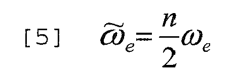
- Inertial torque

- Cylinders Torque

- J1
- moment of inertia of an internal combustion engine 1;
- J2
- moment of inertia of the vehicle reported to the
drive shaft 4; - Keb
- stiffness of the transmission line;
- ρeb
- damping coefficient of the transmission line;
- j
- imaginary unit;
- n
- harmonic order;
- ώe
- pulse;
- ωe
- angular speed of the
drive shaft 4; - Te
- average torque generated by the internal combustion engine 1;
- Talt,n
- alternate torque due to the masses in reciprocating movement;
- meq
- masses in reciprocating movement;
- θalt
- phase factor of the inertia torque (alternate motion);
- Tind
- indicated torque.
- The inverse mechanical model of the transmission H(jώ) is derived from the above three equations [4], [6] and [7] of the direct mechanical model of the transmission by replacing the equation [4] and the equation [6] into the equation [7] and in such a way to link the indicated torque Tind,n to the angular speed ωe,n of the
drive shaft 4; the relationship between the indicated torque Tind,n and the angular speed ωe,n of thedrive shaft 4 provides the inverse mechanical model of the transmission (the final formula of the inverse mechanical model of the transmission has not been reported because it adds no additional information and it is complex to write). It is important to note that in practice an experimental methodology is executed to obtain experimentally by points the transfer function of the inverse mechanical model of the transmission. - It is important to note that in order to obtain precise estimates, the inverse mechanical model H(jώ) of the transmission must consider the inertial torques due to masses in reciprocating movement (i.e. the masses of the pistons 3). So, in order to use directly the equation [3] one must use a complete inverse mechanical model H(jώ) of the transmission that considers the inertial torques due to masses in reciprocating movement (as described by the equation [6]). However, considering the inertial torque due to the masses in reciprocating movement it is complicated and considerably increases the complexity of the determination and experimental calibration in the laboratory of the inverse mechanical model H(jώ) of the transmission.
- The nth torque harmonic Tn is equal to the sum of the indicated nth torque harmonic Tind,n and the alternate indicated nth torque harmonic Talt,n (inertial) (as expressed in equation [8]); this condition also applies in cut-off condition (i.e. in the absence of combustion in
cylinders 2 because of the absence of fuel injection) as expressed in equation [9]. It is important to note that at the same rotation speed (i.e. the same angular speed of rotation), the alternate torques (inertial) are identical regardless of the combustion incylinders 2, because they depend solely on the masses in reciprocating movement; therefore, at the same rotation speed, the alternate nth torque Talt,n is identical to the alternate nth torque harmonic TaltC,n in cut-off condition.

- Tn
- nth torque harmonic;
- Tind,n
- indicated nth torque harmonic;
- Talt,n
- alternate nth torque harmonic;
- TnC
- nth torque harmonic in similar cut-off condition;
- TindC,n
- indicated nth torque harmonic in similar cut-off condition;
- TaltC,n
- alternate nth torque harmonic in similar cut-off condition.
- Consequently, by performing the difference between the equations [8] and [9], at the same rotation speed, and therefore by simplifying the expressions of the alternate torques, one can obtain the equation [10] which relates the indicated nth torque harmonic Tind,n to the difference relatively to similar cut-off conditions (i.e. in the absence of combustion in
cylinders 2 because of the absence of fuel injection and at the same speed).
- Tind,n
- indicated nth harmonic torque;
- Tn
- nth torque harmonic;
- TnC
- nth torque harmonic in similar cut-off conditions;
- TindC,n
- indicated nth torque harmonic in similar cut-off conditions.
- Inserting the equation [3] into the equation [10] the equation [11] below is obtained:

- Tind,n
- indicated nth harmonic torque;
- H(jΩn)
- inverse mechanical model of the transmission;
- Ωn
- nth speed signal harmonic;
- ΩnC
- nth speed signal harmonic in similar cut off condition;
- TindC,n
- indicated nth harmonic torque in similar cut-off condition.
- In equation [11] the indicated nth torque harmonic Tind,n is calculated as the difference relatively to the indicated nth harmonic torque TindC,n in similar cut-off condition (i.e. at the same speed of rotation).
- In equation [11], the inverse mechanical model H(jώ) of the transmission is simplified since it does not consider the inertial torques due to the masses in reciprocating movement. This simplification does not cause any error because the inverse mechanical model H(jώ) of the transmission is used not in absolute terms, but only in derivative term relatively to a similar cut-off condition; by using the inverse mechanical model H(jώ) of the transmission only in derivative terms relatively to a similar cut-off condition, the contribution of the inertial torques due to the masses in reciprocating movement is null and therefore it can be ignored without causing any error (i.e. no approximation)
- Obviously in order to be able to use the equation [11] that consents the use of the simplified inverse mechanical model H(jώ) of the transmission it is necessary to know at all speeds of rotation the parameters in cut-off condition, i.e. nth speed signal harmonic in cut-off condition and the indicated nth harmonic torque in cut-off condition (which are complex numbers characterized by their own module |ΩnC| and |TindC,n| and their own phase Arg(ΩnC) and Arg(TindC,n)).
- For example, it is sufficient to know the parameters in cut-off condition for all the functioning range of the internal combustion engine 1 in terms of frequency (from the maximum to minimum value) by minimum step of 100-300 rpm (and by interpolating in order to obtain the intermediate values).
- In order to determine the parameters in cut-off conditions a first way comports executing a series of measurements even with additional laboratory measurement sensors during a first calibration experimental phase in laboratory.
- In order to determine the parameters in cut-off conditions a first way comports using a learning strategy that is implemented in the
control unit 8 and it is executed during the normal functioning of the internal combustion engine 1 (in particular, the learning strategy can be executed every time the internal combustion engine 1 is in cut-off conditions). This learning strategy requires to determine through simple analysis of frequency of the angular speed ωi compensating the nth speed signal harmonic ΩnC in cut-off conditions and requires to determine the indicated nth harmonic torque TindC,n in cut-off condition by using an algebraic function Λ that uses a set of engine parameters EP of the internal combustion engine 1 according to the following equation:
- TindC,n
- indicated nth harmonic torque in similar cut-off condition;
- EP
- EP set of engine parameters of an internal combustion engine 1 (usually the speed of rotation of
drive shaft 4 and the suction pressure, i.e. the pressure inside an intake manifold). - It is important to note that the algebraic function Λ is at the same time easy to define and has good accuracy since when operating in cut-off condition the combustion torque is null and therefore the remaining torque is only due to pumping and to the masses in reciprocating movement and so it is easy to correlate it to the rotation speed and suction pressure. Normally, one would use an experimental methodology to obtain experimentally through points the algebraic function Λ.
- According to a preferred form of implementation, to determine the parameters in cut-off conditions both ways described above are followed: in a
memory unit 8 of thenew control unit 12 the parameters, determined in cut-off conditions in a experimental calibration phase in laboratory are stored and therefore during the life of the internal combustion engine 1 the parameters in the initial cut-off conditions are continuously (cyclically) updated to follow both the time derivative, and the constructive derivative, i.e. the specificity of the internal combustion engine 1 (the parameters in cut-off conditions stored initially are averages referring to an internal combustion engine 1). - It is worth noting that in the case of estimation of indicated torque Tind and of average MFB50 combustion index of a complete engine cycle (4 consecutive combustions in the four cylinders 2) is sufficient to store a single set of parameter values in cut-off conditions for each cycle of operation of an internal combustion engine 1 (equivalent to four full rotations of the drive shaft 4), otherwise if one wants to estimate the indicated torque Tind and the MFB50 combustion index for each combustion (i.e. for each cylinder) for each operating cycle of the internal combustion engine (equivalent to four full rotations of the drive shaft 4) four sets of parameter values in cut-off conditions should be stored, each corresponding to each cylinder 2 (i.e. calculated in the angular window corresponding to the cylinder 2).
- As shown in
Figure 2 , the calculation block of thecontrol unit 8 uses the inverse mechanical model H(jώ) of the transmission simplified to calculate the indicated nth harmonic torque Tind,n by equation [11] and using the parameters of cut-off condition provided bymemory 12. - As already mentioned above, the harmonic torque Tind,n (like the Ωnof speed signal harmonic) is a complex number characterized by its own module |Tind,n| and its own phase Arg(Tind,n). The module |Tind,n| of the indicated nth harmonic torque Tind,n calculated by the
calculation block 11 is supplied to acalculation block 13, wherein an algebraic function Γ is implemented which relates the indicated torque Tind with the module |Tind,n| of the indicated nth harmonic torque Tind,n using the following equation:
- Tind
- indicated torque;
- |Tind,n|
- module of the indicated nth harmonic torque Tind,n;
- EP
- EP set of engine parameters of an internal combustion engine 1 (usually the speed of rotation of
drive shaft 4 and the suction pressure, i.e. the pressure inside an intake manifold). - As a non-biding example, the algebraic function Γ, which relates the indicated torque Tind with the module |Tind,n| of the indicated nth harmonic torque Tind,n could be defined using the following equation:

- Tind
- indicated torque Tind;
- |Tind,n|
- module of the indicated nth harmonic torque Tind,n;
- p
- suction pressure;
- n
- speed of rotation of the
drive shaft 4; - bi
- coefficients.
- The values of the coefficients bi can be obtained experimentally by minimizing the mean square error between a set of measured values of the indicated torque Tind and a corresponding set of estimated values of the indicated torque Tind.
- The phase Arg(Tind,n) of the harmonic torque Tn calculated by the
calculation block 11 is supplied to acalculation block 14, which implements an algebraic function Ψ that relates the MFB50 combustion index to the phase Arg(Tind,n) of the indicated nth harmonic torque Tn,ind using the following equation:
- MFB50
- MFB50 combustion index;
- Arg(Tind,n)
- phase of the indicated nth harmonic torque Tind,n;
- EP
- set of engine parameters of an internal combustion engine 1 (usually the speed of rotation of
drive shaft 4 and the suction pressure, i.e. the pressure inside an intake manifold). - As non-binding example, the algebraic function Ψ that links the MFB50 combustion index to the phase Arg(Tn,ind) of the indicated nth harmonic torque Tn,ind could be defined using the following equation:

- MFB50
- combustion index;
- Φ
- phase of the indicated nth harmonic torque Tind,n;
- p
- suction pressure;
- ci
- coefficients.
- The values of the coefficients ci can be obtained experimentally by minimizing the mean square error between a set of measured values of the MFB50 combustion index and a corresponding set of estimated values of the MFB50 combustion index.
- In the above equations [3] - [16] the reference has always been to the nth harmonic: the actual order of the nth harmonic (i.e. the actual value of the number "n") depends on the number of
cylinders 2 of the internal combustion engine 1 and the type of estimate desired. For example, it is possible to consider only the harmonic characteristic of the internal combustion engine 1 that depends on the number ofcylinders 2 and on the sequence of combustions (the harmonic of order four for an internal combustion engine with fourcylinders 2 and equispaced combustions). Alternatively, it is possible to consider more harmonics of different order in particular for the relative balancing of thecylinders 2. - According to a possible form of implementation, the equation [11] can be used to derive experimentally the inverse mechanical model H(jώ) of the transmission by expressing the inverse mechanical model H(jώ) of the transmission as a function of the other factors as in equation:

- H(jΩn)
- inverse mechanical model of the transmission;
- Tind,n
- indicated nth harmonic torque;
- TindC,n
- indicated nth harmonic torque in similar cut-off condition;
- Ωn
- nth speed signal harmonic;
- ΩnC
- nth speed signal harmonic in similar cut-off condition.
- During an experimental calibration phase in laboratory, the inverse mechanical model H(jώ) of the transmission is determined by the equation [17] using a series of measurements made by including laboratory measurement sensors that read the pressure inside each
cylinder 2. - The estimation method described above can be used in an internal combustion engine 1 without sensors of pressure that directly measure the pressure inside the
cylinders 2 to estimate the MFB50 combustion index and indicated torque Tind. - Moreover, the estimation method described above can be used in an internal combustion engine 1 equipped, in only a part of the cylinders, with sensors of pressure that directly measure the pressure inside the cylinders to estimate the MFB50 combustion index and the indicated torque Tind related to the cylinders without the sensors of pressure that directly measure the pressure inside the cylinders; in other words, in some cylinders equipped with sensors of pressure the MFB50 combustion index and the indicated torque Tind are calculated by direct measurement of the pressure inside the cylinders, while in other cylinders without pressure sensors the MFB50 combustion index and the indicated torque Tind are calculated using the estimation method described above.
- Finally, the estimation method described above can be used in an internal combustion engine 1 equipped with sensors of
pressure 15 that directly measure the pressure inside thecylinder 2 to diagnose a malfunction of the sensors ofpressure 15 themselves; this diagnosis is obtained by comparing the values of the MFB50 combustion index and the indicated torque Tind determined by measuring the pressure using the values of the MFB50 combustion index and the indicated torque Tind determined by the method of estimating described above: if the difference (in percentage) is too high (i.e. above a predetermined threshold), then a malfunction is diagnosed on the corresponding sensor ofpressure 15. - The method of estimating described above of the MFB50 combustion index and the indicated torque Tind presents a number of advantages, as it is efficient (i.e. it allows to estimate the MFB50 combustion index and the indicated torque Tind with remarkable accuracy), effective (i.e. it allows to estimate the MFB50 combustion index and the indicated torque Tind quickly and without going into excessive computing power) and cost-effective (i.e. it does not require installation of additional components other than those normally found in a modern internal combustion engine operating on "Diesel" cycle).
- Thanks to the ability to estimate the MFB50 combustion index and the indicated torque Tind in each
cylinder 2, it is possible to make a feedback control of the combustion process (using the MFB50 combustion index as a variable feedback) through which it is possible to reduce fuel consumption and pollutant emissions maintaining the same performance; for example, through this feedback control, it is possible to improve significantly the control of the stability of premixed combustion with high EGR rate. Moreover, the MFB50 combustion index in eachcylinder 2 can be advantageously used to govern the stress on connecting rods and the phenomena of detonation. Finally, the indicated torque Tind produced by eachcylinder 2 can be effectively used to further improve the control of the combustion process. - Finally, the method of estimating described above allows the use of an inverse mechanical model H(jώ) of the transmission simplified that does not consider the inertial torques due to masses in reciprocating movement; this simplification on one hand does not cause any error (i.e. no approximation) and on the other hand can significantly reduce the complexity of the inverse mechanical model H(jώ) of the transmission with obvious advantages in terms of computing power required and calibration tests necessary to define the model.
- It is important to clarify that the method of estimating described above has advantageous applications in an internal combustion engine with spontaneous mixture ignition (i.e., operating on diesel cycle) or in an internal combustion engine with controlled ignition of the mixture (i.e. operating according to the Otto cycle).
Claims (6)
- A method of estimating a combustion index (MFB50) and/or the indicated torque (Tind) in a cylinder (2) of a four stroke internal combustion engine (1) with spontaneous mixture ignition provided with a drive shaft (4) coupled to a phonic wheel (5) presenting a number N of teeth (6); the method of estimating comprises the steps of:determining the angular speed (ωi) of the drive shaft (4);determining, by means of a frequency analysis of the angular speed (ωi) of the drive shaft (4), at least one harmonic (Ωn) of the speed signal characterized by its own module (|Ωn|) and is own phase (Arg(Ωn));determining an inverse mechanical model (H(Jώ)) of the transmission which represents, in the (ώ) frequency domain, the relation between the Fourier transforms of the angular speed (Ω) and of the torque (T) of the internal combustion engine (1);determining at least one indicated torque harmonic (Tind,n) characterized by its own module (|Tind,n|) and by its own phase (Arg(Tind,n)) by applying the inverse mechanical model (H(jώ)) of the transmission to the speed signal harmonic (Ωn);determining a first algebraic function (Ψ) which puts the combustion index (MFB50) into relation with the phase (Arg(Tind,n)) of the nth indicated torque harmonic (Tind,n) and/or determining a second algebraic function (Γ) which puts the indicated torque (Tind) into relation with the module (|Tind,n|) of the nth indicated torque harmonic (Tind,n); anddetermining the combustion index (MFB50) by applying the first algebraic function (Ψ) to the nth indicated torque harmonic (Tind,n) and/or determining the indicated torque (Tind) by applying the second algebraic function (Γ) to the nth indicated torque harmonic (Tind,n);the method of estimating is characterized in that the step of determining at least one indicated torque harmonic (Tind,n) uses the following equation:
 Tind,n nth indicated torque harmonic;H(jΩn) inverse mechanical model of the transmission;Ωn nth speed signal harmonic;ΩnC nth speed signal harmonic in analogous cut-off condition;TindC,n nth indicated torque harmonic in analogous cut-off condition.
 - The method of estimating according to claim 1, wherein the inverse mechanical model (H(jώ)) of the transmission does not take into account the inertial torques due to the masses in reciprocating motion of the internal combustion engine (1).
- The method of estimating according to claim 1 or 2, wherein the inverse mechanical model (H(jώ)) of the transmission uses the following equation applied to a series of experimental data related to the whole functioning range of internal combustion engine (1):
 H(jΩn) inverse mechanical model of the transmission;Tind,n nth indicated torque harmonic;TindC,n nth indicated torque harmonic in similar cut-off condition;Ωn nth speed signal harmonic;ΩnC nth speed signal harmonic in similar cut-off condition.
 - The method of estimating according to claim 1, 2 o 3 and comprising the additional step of storing in a memory (12) at any speed of rotation, the parameters in cut-off conditions, i.e. the nth speed signal harmonic (ΩnC) in cut-off condition and the nth indicated torque harmonic (TindC,n) in cut-off condition.
- The method of estimating according to claim 4 and comprising the additional steps of:initially storing in the memory (12) parameters in standard cut-off condition determined during the experimental calibration in laboratory; eupdating cyclically the parameters in cut-off condition during the life of the internal combustion engine (1).
- The method of estimating according to one of the claims from 1 to 5 and comprising the additional steps of:measuring directly the pressure inside the cylinder (2) through a sensor of pressure (15);determining the combustion index (MFB50) and/or the nth indicated torque harmonic (Tind) as a function of the pressure inside the cylinder (2); anddiagnosing the proper functioning of the sensors of pressure (15) by comparing the combustion index (MFB50) and/or the indicated torque (Tind), determined as a function of the pressure inside the cylinder (2), to the corresponding combustion index (MFB50) and/or indicated torque (Tind) determined in accordance with the method of estimating.
Applications Claiming Priority (1)
| Application Number | Priority Date | Filing Date | Title |
|---|---|---|---|
| IT000562A ITBO20100562A1 (en) | 2010-09-16 | 2010-09-16 | ESTIMATION METHOD OF A COMBUSTION AND / OR TORQUE INDEX INDICATED IN A CYLINDER OF AN INTERNAL COMBUSTION ENGINE |
Publications (2)
| Publication Number | Publication Date |
|---|---|
| EP2431595A1 true EP2431595A1 (en) | 2012-03-21 |
| EP2431595B1 EP2431595B1 (en) | 2017-01-04 |
Family
ID=43533471
Family Applications (1)
| Application Number | Title | Priority Date | Filing Date |
|---|---|---|---|
| EP11181724.3A Active EP2431595B1 (en) | 2010-09-16 | 2011-09-16 | Method of estimating a combustion index and/or the indicated torque in a cylinder of a four stroke internal combustion engine with spontaneous mixture ignition |
Country Status (2)
| Country | Link |
|---|---|
| EP (1) | EP2431595B1 (en) |
| IT (1) | ITBO20100562A1 (en) |
Cited By (5)
| Publication number | Priority date | Publication date | Assignee | Title |
|---|---|---|---|---|
| US10227934B2 (en) | 2015-09-29 | 2019-03-12 | Cummins Inc. | Dual-fuel engine combustion mode transition controls |
| CN109526019A (en) * | 2018-12-26 | 2019-03-26 | 国网湖南省电力有限公司 | Wireless private network base station range propagation model revision method based on measured data |
| IT202200013879A1 (en) | 2022-06-30 | 2023-12-30 | Marelli Europe Spa | METHOD FOR ESTIMATING THE MAXIMUM PRESSURE INSIDE A COMBUSTION CHAMBER OF A CYLINDER OF AN INTERNAL COMBUSTION ENGINE |
| DE102019207252B4 (en) | 2018-11-14 | 2024-09-12 | Vitesco Technologies GmbH | Recording of cylinder-specific combustion process parameter values for an internal combustion engine |
| DE102018131438B4 (en) | 2017-12-08 | 2025-09-04 | GM Global Technology Operations LLC | METHOD AND DEVICE FOR CONTROLLING A MULTI-CYLINDER INTERNAL COMBUSTION ENGINE |
Families Citing this family (1)
| Publication number | Priority date | Publication date | Assignee | Title |
|---|---|---|---|---|
| FR3129983B1 (en) | 2021-12-08 | 2023-10-27 | Vitesco Technologies | motor control method and device |
Citations (2)
| Publication number | Priority date | Publication date | Assignee | Title |
|---|---|---|---|---|
| EP2022967A1 (en) | 2007-07-25 | 2009-02-11 | Magneti Marelli Powertrain S.p.A. | Method for estimating the crank angle at which the 50% mass fraction burn time occurs in an intenral combustion engine |
| US20090312931A1 (en) * | 2008-06-16 | 2009-12-17 | Gm Global Technology Operations, Inc. | Fuel system injection timing diagnostics by analyzing cylinder pressure signal |
-
2010
- 2010-09-16 IT IT000562A patent/ITBO20100562A1/en unknown
-
2011
- 2011-09-16 EP EP11181724.3A patent/EP2431595B1/en active Active
Patent Citations (2)
| Publication number | Priority date | Publication date | Assignee | Title |
|---|---|---|---|---|
| EP2022967A1 (en) | 2007-07-25 | 2009-02-11 | Magneti Marelli Powertrain S.p.A. | Method for estimating the crank angle at which the 50% mass fraction burn time occurs in an intenral combustion engine |
| US20090312931A1 (en) * | 2008-06-16 | 2009-12-17 | Gm Global Technology Operations, Inc. | Fuel system injection timing diagnostics by analyzing cylinder pressure signal |
Cited By (6)
| Publication number | Priority date | Publication date | Assignee | Title |
|---|---|---|---|---|
| US10227934B2 (en) | 2015-09-29 | 2019-03-12 | Cummins Inc. | Dual-fuel engine combustion mode transition controls |
| DE102018131438B4 (en) | 2017-12-08 | 2025-09-04 | GM Global Technology Operations LLC | METHOD AND DEVICE FOR CONTROLLING A MULTI-CYLINDER INTERNAL COMBUSTION ENGINE |
| DE102019207252B4 (en) | 2018-11-14 | 2024-09-12 | Vitesco Technologies GmbH | Recording of cylinder-specific combustion process parameter values for an internal combustion engine |
| CN109526019A (en) * | 2018-12-26 | 2019-03-26 | 国网湖南省电力有限公司 | Wireless private network base station range propagation model revision method based on measured data |
| IT202200013879A1 (en) | 2022-06-30 | 2023-12-30 | Marelli Europe Spa | METHOD FOR ESTIMATING THE MAXIMUM PRESSURE INSIDE A COMBUSTION CHAMBER OF A CYLINDER OF AN INTERNAL COMBUSTION ENGINE |
| EP4299889A1 (en) | 2022-06-30 | 2024-01-03 | Marelli Europe S.p.A. | Method to estimate the maximum pressure inside a combustion chamber of a cylinder of an internal combustion engine |
Also Published As
| Publication number | Publication date |
|---|---|
| EP2431595B1 (en) | 2017-01-04 |
| ITBO20100562A1 (en) | 2012-03-17 |
Similar Documents
| Publication | Publication Date | Title |
|---|---|---|
| EP2136061B1 (en) | Method for determining the average rotational speed of a crankshaft in an internal combustion engine | |
| US9399963B2 (en) | Misfire detection system | |
| EP2431595B1 (en) | Method of estimating a combustion index and/or the indicated torque in a cylinder of a four stroke internal combustion engine with spontaneous mixture ignition | |
| US7623955B1 (en) | Method for estimation of indicated mean effective pressure for individual cylinders from crankshaft acceleration | |
| US8256278B2 (en) | Engine misfire detection systems and methods using discrete fourier transform approximation | |
| EP2180178B1 (en) | Method of detecting knock in an internal combustion engine | |
| JP4276685B2 (en) | Abnormality detection device and abnormality detection method for internal combustion engine | |
| US10139314B2 (en) | Misfire detection device to detect misfire based on a frequency analysis of a rotation signal correlated with a rotational state of an internal combustion engine | |
| US20060259229A1 (en) | Method and device for determining an angular position signal of an internal combustion | |
| JP5488561B2 (en) | Internal combustion engine learning device | |
| US10739232B2 (en) | Method of estimating the MFB50 combustion index and the instantaneous torque generated by the cylinders of an internal combustion engine | |
| EP1559898B1 (en) | Method for determining the variation of engine speed | |
| JP4626564B2 (en) | Control device for internal combustion engine | |
| EP1515130A1 (en) | Method for finding the angular acceleration of a drive shaft of an internal combustion engine by means of a gear wheel integral with said drive shaft | |
| Ponti et al. | Remote combustion sensing methodology for non-intrusive cylinder pressure estimation in diesel engines | |
| EP2078841B1 (en) | Monitoring unit and method | |
| JP2007211721A (en) | Control device for internal combustion engine | |
| Yoneya et al. | Combustion torque estimation from mass-produced crank angle sensor | |
| JP2006194178A (en) | Fuel flow measuring device for internal combustion engine | |
| ITBO20120023A1 (en) | ESTIMATE METHOD OF TORQUE UNBALANCE INDICATED PROVIDED BY THE CYLINDERS OF AN INTERNAL COMBUSTION ENGINE |
Legal Events
| Date | Code | Title | Description |
|---|---|---|---|
| PUAI | Public reference made under article 153(3) epc to a published international application that has entered the european phase |
Free format text: ORIGINAL CODE: 0009012 |
|
| AK | Designated contracting states |
Kind code of ref document: A1 Designated state(s): AL AT BE BG CH CY CZ DE DK EE ES FI FR GB GR HR HU IE IS IT LI LT LU LV MC MK MT NL NO PL PT RO RS SE SI SK SM TR |
|
| AX | Request for extension of the european patent |
Extension state: BA ME |
|
| 17P | Request for examination filed |
Effective date: 20120920 |
|
| GRAP | Despatch of communication of intention to grant a patent |
Free format text: ORIGINAL CODE: EPIDOSNIGR1 |
|
| INTG | Intention to grant announced |
Effective date: 20160728 |
|
| STAA | Information on the status of an ep patent application or granted ep patent |
Free format text: STATUS: GRANT OF PATENT IS INTENDED |
|
| GRAS | Grant fee paid |
Free format text: ORIGINAL CODE: EPIDOSNIGR3 |
|
| GRAA | (expected) grant |
Free format text: ORIGINAL CODE: 0009210 |
|
| STAA | Information on the status of an ep patent application or granted ep patent |
Free format text: STATUS: THE PATENT HAS BEEN GRANTED |
|
| AK | Designated contracting states |
Kind code of ref document: B1 Designated state(s): AL AT BE BG CH CY CZ DE DK EE ES FI FR GB GR HR HU IE IS IT LI LT LU LV MC MK MT NL NO PL PT RO RS SE SI SK SM TR |
|
| REG | Reference to a national code |
Ref country code: GB Ref legal event code: FG4D |
|
| REG | Reference to a national code |
Ref country code: CH Ref legal event code: EP |
|
| REG | Reference to a national code |
Ref country code: AT Ref legal event code: REF Ref document number: 859473 Country of ref document: AT Kind code of ref document: T Effective date: 20170115 |
|
| REG | Reference to a national code |
Ref country code: IE Ref legal event code: FG4D |
|
| REG | Reference to a national code |
Ref country code: DE Ref legal event code: R096 Ref document number: 602011033979 Country of ref document: DE |
|
| REG | Reference to a national code |
Ref country code: LT Ref legal event code: MG4D Ref country code: NL Ref legal event code: MP Effective date: 20170104 |
|
| REG | Reference to a national code |
Ref country code: AT Ref legal event code: MK05 Ref document number: 859473 Country of ref document: AT Kind code of ref document: T Effective date: 20170104 |
|
| PG25 | Lapsed in a contracting state [announced via postgrant information from national office to epo] |
Ref country code: NL Free format text: LAPSE BECAUSE OF FAILURE TO SUBMIT A TRANSLATION OF THE DESCRIPTION OR TO PAY THE FEE WITHIN THE PRESCRIBED TIME-LIMIT Effective date: 20170104 |
|
| PG25 | Lapsed in a contracting state [announced via postgrant information from national office to epo] |
Ref country code: LT Free format text: LAPSE BECAUSE OF FAILURE TO SUBMIT A TRANSLATION OF THE DESCRIPTION OR TO PAY THE FEE WITHIN THE PRESCRIBED TIME-LIMIT Effective date: 20170104 Ref country code: GR Free format text: LAPSE BECAUSE OF FAILURE TO SUBMIT A TRANSLATION OF THE DESCRIPTION OR TO PAY THE FEE WITHIN THE PRESCRIBED TIME-LIMIT Effective date: 20170405 Ref country code: IS Free format text: LAPSE BECAUSE OF FAILURE TO SUBMIT A TRANSLATION OF THE DESCRIPTION OR TO PAY THE FEE WITHIN THE PRESCRIBED TIME-LIMIT Effective date: 20170504 Ref country code: FI Free format text: LAPSE BECAUSE OF FAILURE TO SUBMIT A TRANSLATION OF THE DESCRIPTION OR TO PAY THE FEE WITHIN THE PRESCRIBED TIME-LIMIT Effective date: 20170104 Ref country code: NO Free format text: LAPSE BECAUSE OF FAILURE TO SUBMIT A TRANSLATION OF THE DESCRIPTION OR TO PAY THE FEE WITHIN THE PRESCRIBED TIME-LIMIT Effective date: 20170404 Ref country code: HR Free format text: LAPSE BECAUSE OF FAILURE TO SUBMIT A TRANSLATION OF THE DESCRIPTION OR TO PAY THE FEE WITHIN THE PRESCRIBED TIME-LIMIT Effective date: 20170104 |
|
| REG | Reference to a national code |
Ref country code: FR Ref legal event code: PLFP Year of fee payment: 7 |
|
| PG25 | Lapsed in a contracting state [announced via postgrant information from national office to epo] |
Ref country code: RS Free format text: LAPSE BECAUSE OF FAILURE TO SUBMIT A TRANSLATION OF THE DESCRIPTION OR TO PAY THE FEE WITHIN THE PRESCRIBED TIME-LIMIT Effective date: 20170104 Ref country code: AT Free format text: LAPSE BECAUSE OF FAILURE TO SUBMIT A TRANSLATION OF THE DESCRIPTION OR TO PAY THE FEE WITHIN THE PRESCRIBED TIME-LIMIT Effective date: 20170104 Ref country code: BG Free format text: LAPSE BECAUSE OF FAILURE TO SUBMIT A TRANSLATION OF THE DESCRIPTION OR TO PAY THE FEE WITHIN THE PRESCRIBED TIME-LIMIT Effective date: 20170404 Ref country code: ES Free format text: LAPSE BECAUSE OF FAILURE TO SUBMIT A TRANSLATION OF THE DESCRIPTION OR TO PAY THE FEE WITHIN THE PRESCRIBED TIME-LIMIT Effective date: 20170104 Ref country code: PT Free format text: LAPSE BECAUSE OF FAILURE TO SUBMIT A TRANSLATION OF THE DESCRIPTION OR TO PAY THE FEE WITHIN THE PRESCRIBED TIME-LIMIT Effective date: 20170504 Ref country code: SE Free format text: LAPSE BECAUSE OF FAILURE TO SUBMIT A TRANSLATION OF THE DESCRIPTION OR TO PAY THE FEE WITHIN THE PRESCRIBED TIME-LIMIT Effective date: 20170104 Ref country code: PL Free format text: LAPSE BECAUSE OF FAILURE TO SUBMIT A TRANSLATION OF THE DESCRIPTION OR TO PAY THE FEE WITHIN THE PRESCRIBED TIME-LIMIT Effective date: 20170104 Ref country code: LV Free format text: LAPSE BECAUSE OF FAILURE TO SUBMIT A TRANSLATION OF THE DESCRIPTION OR TO PAY THE FEE WITHIN THE PRESCRIBED TIME-LIMIT Effective date: 20170104 |
|
| REG | Reference to a national code |
Ref country code: DE Ref legal event code: R097 Ref document number: 602011033979 Country of ref document: DE |
|
| PG25 | Lapsed in a contracting state [announced via postgrant information from national office to epo] |
Ref country code: EE Free format text: LAPSE BECAUSE OF FAILURE TO SUBMIT A TRANSLATION OF THE DESCRIPTION OR TO PAY THE FEE WITHIN THE PRESCRIBED TIME-LIMIT Effective date: 20170104 Ref country code: RO Free format text: LAPSE BECAUSE OF FAILURE TO SUBMIT A TRANSLATION OF THE DESCRIPTION OR TO PAY THE FEE WITHIN THE PRESCRIBED TIME-LIMIT Effective date: 20170104 Ref country code: CZ Free format text: LAPSE BECAUSE OF FAILURE TO SUBMIT A TRANSLATION OF THE DESCRIPTION OR TO PAY THE FEE WITHIN THE PRESCRIBED TIME-LIMIT Effective date: 20170104 Ref country code: SK Free format text: LAPSE BECAUSE OF FAILURE TO SUBMIT A TRANSLATION OF THE DESCRIPTION OR TO PAY THE FEE WITHIN THE PRESCRIBED TIME-LIMIT Effective date: 20170104 |
|
| PLBE | No opposition filed within time limit |
Free format text: ORIGINAL CODE: 0009261 |
|
| STAA | Information on the status of an ep patent application or granted ep patent |
Free format text: STATUS: NO OPPOSITION FILED WITHIN TIME LIMIT |
|
| PG25 | Lapsed in a contracting state [announced via postgrant information from national office to epo] |
Ref country code: DK Free format text: LAPSE BECAUSE OF FAILURE TO SUBMIT A TRANSLATION OF THE DESCRIPTION OR TO PAY THE FEE WITHIN THE PRESCRIBED TIME-LIMIT Effective date: 20170104 Ref country code: SM Free format text: LAPSE BECAUSE OF FAILURE TO SUBMIT A TRANSLATION OF THE DESCRIPTION OR TO PAY THE FEE WITHIN THE PRESCRIBED TIME-LIMIT Effective date: 20170104 |
|
| 26N | No opposition filed |
Effective date: 20171005 |
|
| PG25 | Lapsed in a contracting state [announced via postgrant information from national office to epo] |
Ref country code: SI Free format text: LAPSE BECAUSE OF FAILURE TO SUBMIT A TRANSLATION OF THE DESCRIPTION OR TO PAY THE FEE WITHIN THE PRESCRIBED TIME-LIMIT Effective date: 20170104 |
|
| REG | Reference to a national code |
Ref country code: CH Ref legal event code: PL |
|
| GBPC | Gb: european patent ceased through non-payment of renewal fee |
Effective date: 20170916 |
|
| PG25 | Lapsed in a contracting state [announced via postgrant information from national office to epo] |
Ref country code: MC Free format text: LAPSE BECAUSE OF FAILURE TO SUBMIT A TRANSLATION OF THE DESCRIPTION OR TO PAY THE FEE WITHIN THE PRESCRIBED TIME-LIMIT Effective date: 20170104 |
|
| REG | Reference to a national code |
Ref country code: IE Ref legal event code: MM4A |
|
| REG | Reference to a national code |
Ref country code: BE Ref legal event code: MM Effective date: 20170930 |
|
| PG25 | Lapsed in a contracting state [announced via postgrant information from national office to epo] |
Ref country code: LU Free format text: LAPSE BECAUSE OF NON-PAYMENT OF DUE FEES Effective date: 20170916 |
|
| PG25 | Lapsed in a contracting state [announced via postgrant information from national office to epo] |
Ref country code: CH Free format text: LAPSE BECAUSE OF NON-PAYMENT OF DUE FEES Effective date: 20170930 Ref country code: IE Free format text: LAPSE BECAUSE OF NON-PAYMENT OF DUE FEES Effective date: 20170916 Ref country code: LI Free format text: LAPSE BECAUSE OF NON-PAYMENT OF DUE FEES Effective date: 20170930 Ref country code: GB Free format text: LAPSE BECAUSE OF NON-PAYMENT OF DUE FEES Effective date: 20170916 |
|
| REG | Reference to a national code |
Ref country code: FR Ref legal event code: PLFP Year of fee payment: 8 |
|
| PG25 | Lapsed in a contracting state [announced via postgrant information from national office to epo] |
Ref country code: BE Free format text: LAPSE BECAUSE OF NON-PAYMENT OF DUE FEES Effective date: 20170930 |
|
| PG25 | Lapsed in a contracting state [announced via postgrant information from national office to epo] |
Ref country code: MT Free format text: LAPSE BECAUSE OF NON-PAYMENT OF DUE FEES Effective date: 20170916 |
|
| PG25 | Lapsed in a contracting state [announced via postgrant information from national office to epo] |
Ref country code: HU Free format text: LAPSE BECAUSE OF FAILURE TO SUBMIT A TRANSLATION OF THE DESCRIPTION OR TO PAY THE FEE WITHIN THE PRESCRIBED TIME-LIMIT; INVALID AB INITIO Effective date: 20110916 |
|
| PG25 | Lapsed in a contracting state [announced via postgrant information from national office to epo] |
Ref country code: CY Free format text: LAPSE BECAUSE OF NON-PAYMENT OF DUE FEES Effective date: 20170104 |
|
| PG25 | Lapsed in a contracting state [announced via postgrant information from national office to epo] |
Ref country code: MK Free format text: LAPSE BECAUSE OF FAILURE TO SUBMIT A TRANSLATION OF THE DESCRIPTION OR TO PAY THE FEE WITHIN THE PRESCRIBED TIME-LIMIT Effective date: 20170104 |
|
| PG25 | Lapsed in a contracting state [announced via postgrant information from national office to epo] |
Ref country code: AL Free format text: LAPSE BECAUSE OF FAILURE TO SUBMIT A TRANSLATION OF THE DESCRIPTION OR TO PAY THE FEE WITHIN THE PRESCRIBED TIME-LIMIT Effective date: 20170104 |
|
| PG25 | Lapsed in a contracting state [announced via postgrant information from national office to epo] |
Ref country code: TR Free format text: LAPSE BECAUSE OF NON-PAYMENT OF DUE FEES Effective date: 20170916 |
|
| PGFP | Annual fee paid to national office [announced via postgrant information from national office to epo] |
Ref country code: DE Payment date: 20250820 Year of fee payment: 15 |
|
| PGFP | Annual fee paid to national office [announced via postgrant information from national office to epo] |
Ref country code: IT Payment date: 20250820 Year of fee payment: 15 |
|
| PGFP | Annual fee paid to national office [announced via postgrant information from national office to epo] |
Ref country code: FR Payment date: 20250820 Year of fee payment: 15 |