EP2431236A1 - Bumper for vehicles - Google Patents
Bumper for vehicles Download PDFInfo
- Publication number
- EP2431236A1 EP2431236A1 EP11169491A EP11169491A EP2431236A1 EP 2431236 A1 EP2431236 A1 EP 2431236A1 EP 11169491 A EP11169491 A EP 11169491A EP 11169491 A EP11169491 A EP 11169491A EP 2431236 A1 EP2431236 A1 EP 2431236A1
- Authority
- EP
- European Patent Office
- Prior art keywords
- frame
- bumper according
- appendage
- bumper
- covers
- Prior art date
- Legal status (The legal status is an assumption and is not a legal conclusion. Google has not performed a legal analysis and makes no representation as to the accuracy of the status listed.)
- Withdrawn
Links
Images


Classifications
-
- B—PERFORMING OPERATIONS; TRANSPORTING
- B60—VEHICLES IN GENERAL
- B60R—VEHICLES, VEHICLE FITTINGS, OR VEHICLE PARTS, NOT OTHERWISE PROVIDED FOR
- B60R19/00—Wheel guards; Radiator guards, e.g. grilles; Obstruction removers; Fittings damping bouncing force in collisions
- B60R19/02—Bumpers, i.e. impact receiving or absorbing members for protecting vehicles or fending off blows from other vehicles or objects
- B60R19/48—Bumpers, i.e. impact receiving or absorbing members for protecting vehicles or fending off blows from other vehicles or objects combined with, or convertible into, other devices or objects, e.g. bumpers combined with road brushes, bumpers convertible into beds
- B60R19/50—Bumpers, i.e. impact receiving or absorbing members for protecting vehicles or fending off blows from other vehicles or objects combined with, or convertible into, other devices or objects, e.g. bumpers combined with road brushes, bumpers convertible into beds with lights or registration plates
-
- B—PERFORMING OPERATIONS; TRANSPORTING
- B60—VEHICLES IN GENERAL
- B60R—VEHICLES, VEHICLE FITTINGS, OR VEHICLE PARTS, NOT OTHERWISE PROVIDED FOR
- B60R13/00—Elements for body-finishing, identifying, or decorating; Arrangements or adaptations for advertising purposes
- B60R13/10—Registration, licensing, or like devices
- B60R13/105—Licence- or registration plates, provided with mounting means, e.g. frames, holders, retainers, brackets
Definitions
- the second known solution while lending itself to providing a more robust bumper for the same weight, exhibits the problem of needing to be subjected to different machining operations for customization (drilling and cutting), for fixing the essential accessories, which include luminaires, which are powered by electricity.
- the frame 2 has its lateral ends open, which can therefore be closed by means of adapted caps 8a, 8b.
Landscapes
- Engineering & Computer Science (AREA)
- Mechanical Engineering (AREA)
- Body Structure For Vehicles (AREA)
Abstract
A bumper for vehicles which is constituted by a hollow tubular frame, which can be closed laterally by means of adapted caps.
The hollow tubular frame has, in an upper region and longitudinally, an open cavity which defines a seat for wires.
This open cavity can be closed by means of a plurality of covers.
A support protrudes from one or more of these covers for a light and/or a registration plate and/or a tail-light.
Description
- The present invention relates to a bumper for vehicles.
- Nowadays bumpers are known for industrial vehicles which are formed from sheet metal or alloys, so as to define a bar that has profiles which, in addition to the object of giving the bar a robust structure, include slightly recessed spaces to define seats where essential accessories, such as tail-lights, registration plates, indicator lights and the like are then mounted. Bumpers are also known which are formed by a process of extrusion of metal or light alloy: these bumpers have closed sections that provide, for the same weight, greater robustness.
- The first solution exhibits a structural disadvantage, since in Italy there is a regulation (Directive 70/221/CEE and subsequent modification 2006/20/CE) that imposes a resistance threshold on bumpers which is such as to require the use of sheets of considerable thickness; this fact heavily penalises the product from the point of view of costs and sustainability.
- We must also keep in mind that the weight of the bumper ends up burdening on every vehicle that mounts it, since it reduces the overall weight that can be loaded and it also increases the consumption of fuel.
- The second known solution, while lending itself to providing a more robust bumper for the same weight, exhibits the problem of needing to be subjected to different machining operations for customization (drilling and cutting), for fixing the essential accessories, which include luminaires, which are powered by electricity.
- This consideration reveals a further disadvantage of both types of solution described, which is the problem of managing the electrical wires that power the accessories which in turn are fixed to the bumper.
- These are commonly fixed along the longitudinal extension of the bumper by using bands or clamps which in turn are fixed to the bumper with mechanical means.
- It follows from this that the wiring and the connectors are in any case exposed to the elements and to potential physical damage owing to abrasion, ice, snow or simply impacts with bodies such as stones or other objects that a vehicle encounters in its travels on sealed and unsealed surfaces.
- The aim of the present invention is therefore to solve the above mentioned technical problems, eliminating the drawbacks in the cited known art, by providing a bumper for vehicles which is simple to implement, has a low overall weight and is easy to position and wire for the various wires for powering lights and/or tail-lights.
- Within this aim, an object of the invention is to make a bumper that meets the regulations in force regarding structural rigidity while maintaining a high overall lightness.
- Another object is to provide a bumper that makes it possible to achieve the total integration of the functions of accommodating the accessories, accommodating and handling the wiring, and protecting both the accessories and the wiring.
- Another object is to provide a bumper that has a great flexibility of configuration for the wiring and the positioning of the accessories according to the requirements of different markets, such configuration being obtainable in the absence of specific drilling or machining operations.
- Another object is to provide a bumper that can be customised according to specific requirements.
- Another object is to provide a bumper that is structurally simple and is also low cost.
- This aim, as well as these and other objects which will become better evident hereinafter, are achieved by a bumper for vehicles, characterized in that it is constituted by a hollow tubular frame, which can be closed laterally by means of adapted caps and which has, in an upper region and longitudinally, an open cavity, which defines a seat for wires, and can be closed by means of a plurality of covers, a support protruding from one or more of said covers for a light and/or a registration plate and/or a tail-light.
- Further characteristics and advantages of the invention will become better apparent from the detailed description of a particular, but not exclusive, embodiment, illustrated by way of non-limiting example in the accompanying drawings wherein:
-
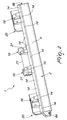
Figure 1 is a perspective view of the bumper of the invention from the front; -
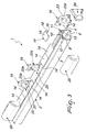
Figure 2 is a perspective view of the bumper from the rear; -
Figure 3 is a partially exploded view of the bumper; -
Figure 4 is a sectional view of the hollow tubular frame; -
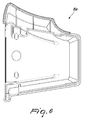
Figures 5 and6 are two views of one of the caps; -
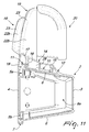
Figure 7 is a perspective view of one of the supports from the rear; -
Figure 8 is a side view of the support in the previous figure; -
Figure 9 is a view of a second type of support, in a view similar to that ofFigure 7 ; -
Figure 10 is a side view of the support in the previous figure; -
Figure 11 is a sectional view taken along the line XI-XI inFigure 1 . - In the embodiments that follow, individual characteristics shown in relation to specific examples may in reality be interchanged with other, different characteristics, existing in other embodiments.
- With reference to the figures, the reference numeral 1 designates a bumper for vehicles, that is illustrated, only for description purposes, as a rear bumper.
- The bumper 1 is constituted by a
frame 2, which is tubular and hollow, and which is preferably constituted by an extruded profile in light alloy exhibiting a shape, in cross-section, that is basically box-like, and preferably having the shape of an isosceles trapezoid. - The
frame 2 thus has afirst front wall 3 that is smooth and a secondrear wall 4 at the ends of which are defined, along a longitudinal axis of theframe 2,first guides frame 2 to the vehicle by way of known means. - Below the
first guide 5b, arranged under theframe 2, asecond guide 7 is provided, which acts as a connector to a thirdlower wall 6 of theframe 2 and is adapted to allow the mounting and/or fixing of a splash guard strip, preferably made of rubberlike material, which is aimed at stopping debris thrown up by the rear wheels of the vehicle. - The
frame 2 has its lateral ends open, which can therefore be closed by means of adaptedcaps - At least one
cavity 10 is obtained, outside theframe 2, at a fourthupper wall 9, thecavity 10 longitudinally affecting theframe 2 and being defined by the presence of a thirdrear guide 11 and afourth front guide 12 which are respectively T-shaped and L-shaped. - The third and the
fourth guide upper wall 9, thus thereon defining a seat for example for adaptedwires 13 for powering various different devices. - The
cavity 10 is temporarily and, selectively for part of its length, closeable by means of a plurality ofcovers 14, each one of which is constituted by a variously shaped profile which has at one end afirst appendage 15, which is shaped so as to complement thefourth front guide 12, and, in an intermediate region, asecond appendage 16, which is adapted to interlock at oneflange 17 of the thirdrear guide 11. - A third
rear appendage 18 is also provided, which is connected to theunderlying frame 2 in a region that is arranged above thefirst guide 5a. - The coupling of the
covers 14 to theframe 2 occurs by means of a sliding coupling, or, preferably, by means of a snap-acting interconnection, which allows the simple inspection of the desired section of the bumper structure. - If the coupling is a snap-acting interconnection, then following the positioning of the
first appendage 15 at thefourth front guide 12, the snap-fit coupling of thesecond appendage 16, which has a suitable undercut, is forced on theflange 17. -
Covers 14 are also provided, from which asupport 19 protrudes for a light and/or a tail-light 20 and/or aregistration plate 21. - The
support 19 can protrude from asingle cover 14 or from a pair of covers arranged side by side or from acover 14 that has the right length upon which to rest the desiredsupport 19. - The
support 19 thus has a dimension, either in width or in depth or in height, which can vary according to the specific device which is associated with it. - Each support thus has a pair of fifth
lateral walls rear wall 23. - Each
support 19 thus has a box-like structure that is open in the direction of thefirst front wall 3 of theframe 2, eachsupport 19 comprising adapted ribs orprotrusions 24 which are provided withfixing means 25 for accessories, such as a tail-light, or a light or aflat surface 26, suitably perforated for the interconnection of a registration plate or of other accessories. - The presence of the
ribs 24 moreover defines adapted seats for further components such as for example the electrical connector that is located in the rear part of the tail-light. - Advantageously a slot or
groove 27 is also provided in at least onesupport 19, specifically in thesupport 9 that has theflat surface 26, so as to allow the accommodation for example of the electrical wire of a tail-light or the like for its routing to theunderlying cavity 10. - In one or more of the
covers 14 there can be afourth appendage 28, which is essentially L-shaped and protrudes downward in an intermediate region between thefirst appendage 15 and thesecond appendage 16 and is connected to thesecond appendage 16; the function of thefourth appendage 28 is to increase the stability of theoverlying support 19. - In practice it has been found that the invention fully achieves the intended aim and objects, a bumper for vehicles being provided which is simple to implement and in the assembly of the different components so as to obtain a desired conformation according to the specific requirements and models to be obtained, all by simply making a choice of the number and of the position of the various different components to be mounted on the frame.
- The bumper that is obtained further meets the regulations in force regarding structural rigidity while maintaining a high overall lightness.
- The bumper further makes it possible to achieve the total integration of the functions of accommodating the accessories, accommodating and handling the wiring, and protecting both the accessories and the wiring.
- Finally, the bumper has a great flexibility of configuration for the wiring and the positioning of the accessories according to the requirements of different markets, such configuration being obtainable in the absence of specific drilling or machining operations, it being moreover possible to achieve, rapidly and simply, the customization of the bumper according to specific requirements.
- Obviously the invention, thus conceived, is susceptible of numerous modifications and variations, all of which are within the scope of the appended claims.
- Obviously the materials used as well as the dimensions constituting the individual components of the invention can be more relevant according to specific requirements.
- The various different means for performing certain different functions shall not in any way coexist only in the illustrated embodiment, but may be present per se in many embodiments, even if not illustrated.
- The characteristics indicated as advantageous, advisable or similar, may also be missing or be substituted by equivalent characteristics.
- The disclosures in Italian Utility Model Application No.
TV2010U000043 - Where technical features mentioned in any claim are followed by reference signs, those reference signs have been included for the sole purpose of increasing the intelligibility of the claims and accordingly, such reference signs do not have any limiting effect on the interpretation of each element identified by way of example by such reference signs.
Claims (19)
- A bumper (1) for vehicles, characterized in that it is constituted by a hollow tubular frame (2), which can be closed laterally by means of caps (8a, 8b) and which has, in an upper region and longitudinally, at least one open cavity (10), which defines a seat for wires, and can be closed by means of a plurality of covers (14), a support (19) protruding from one or more of said covers (14) for a light and/or a registration plate and/or a tail-light.
- The bumper according to claim 1, characterized in that said hollow tubular frame (2) is preferably constituted by an extruded profile in light alloy which has a box-like shape and in cross-section has a shape that is an isosceles trapezoid, said frame (2) having a first front wall (3) that is smooth and a second rear wall (4) at the ends of which , along a longitudinal axis of said frame (2), first guides (5a, 5b) are defined, which constitute means for anchoring and/or fixing said frame (2) to the vehicle.
- The bumper according to claims 1 and 2, characterized in that below said first guide (5b), arranged under said frame (2), a second guide (7) is provided , which acts as a connector to a third lower wall (6) of said frame (2) and which is adapted to allow the mounting and/or fixing of a splash guard strip aimed at stopping debris thrown up by the rear wheels of the vehicle.
- The bumper according to claims 1 and 2, characterized in that said frame (2) has the lateral ends open, which can be closed by means of caps (8a, 8b).
- The bumper according to claims 1 and 2, characterized in that at least one cavity (10) is obtained on the outside of a fourth upper wall (9) of said frame (2), said at least one cavity (10) longitudinally affecting said frame (2) and being defined by the presence of a third rear guide (11) and a fourth front guide (12) which are respectively T-shaped and L-shaped.
- The bumper according to claims 1 and 5, characterized in that said third and fourth guides (11, 12) protrude slightly beyond said fourth upper wall (9), thereon defining a seat for adapted wires (13) for powering various different devices.
- The bumper according to claims 1 and 6, characterized in that said cavity (10) is temporarily and, selectively for part of its length, closeable by means of a plurality of covers (14).
- The bumper according to claims 1 and 7 characterized in that each one of said covers (14) is constituted by a variously shaped profile which has at one end a first appendage (15), which is shaped so as to complement said fourth front guide (12), and, in an intermediate region, at least one second appendage (16), which is adapted to be connected so that it can slide or interlock at one flange (17) of said third rear guide (11).
- The bumper according to one or more of the preceding claims, characterized in that it comprises a third rear appendage (18) which is connected to said, underlying, frame (2) in a region that is arranged above said first guide (5a).
- The bumper according to one or more of the preceding claims, characterized in that the coupling of said covers (14) to said frame (2) occurs by means of a sliding coupling.
- The bumper according to one or more of the preceding claims, characterized in that the coupling of said covers (14) to said frame (2) occurs by means of a snap-acting interconnection, which allows the simple inspection of the desired section of the bumper structure.
- The bumper according to claims 1 and 11 characterized in that, following the positioning of said first appendage (15) at said fourth front guide (12), the snap-fit coupling of said second appendage (16), which has a suitable undercut, is forced on said flange (17).
- The bumper according to one or more of the preceding claims, characterized in that from one or more of said covers (14) a support (19) protrudes for a light and/or a tail-light (20) and/or a registration plate (21).
- The bumper according to claims 1 and 13, characterized in that said support (19) protrudes from a single cover (14) or from a pair of covers (14) arranged side by side or from a cover (14) that has the right length upon which to rest the desired support (19).
- The bumper according to claims 1 and 14, characterized in that said support (19) has a dimension, either in width or in depth or in height, which can vary according to the specific device which is associated with it.
- The bumper according to claims 1 and 14, characterized in that each one of said supports (19) has a pair of fifth lateral walls (22a, 22b) which are connected by a sixth rear wall (23), each one of said supports (19) having a box-like structure that is open in the direction of said first front wall (3) of said frame (2).
- The bumper according to one or more of the preceding claims, characterized in that each one of said supports (19) comprise adapted ribs or protrusions (24) which are provided with fixing means (25) for accessories, such as a tail-light, or a light or a flat surface (26), suitably perforated for the interconnection of a registration plate or of other accessories, said ribs (24) defining adapted seats for further components such as the electrical connector that is located in the rear part of the tail-light.
- The bumper according to one or more of the preceding claims, characterized in that at least one of said supports (19) comprises a slot or groove (27) that is adapted to allow the accommodation of the electrical wire of a tail-light or the like for its routing to the underlying cavity (10).
- The bumper according to one or more of the preceding claims, characterized in that in one or more of said covers (14) a fourth appendage (28) is provided, which is essentially L-shaped and protrudes downward in an intermediate region between said first appendage (15) and second appendage (16) and is connected to said second appendage (16), said fourth appendage (28) thus increasing the stability of said, overlying, support (19).
Applications Claiming Priority (1)
| Application Number | Priority Date | Filing Date | Title |
|---|---|---|---|
| ITTV20100043 ITTV20100043U1 (en) | 2010-09-21 | 2010-09-21 | REAR BUMPER STRUCTURE FOR VEHICLES |
Publications (1)
| Publication Number | Publication Date |
|---|---|
| EP2431236A1 true EP2431236A1 (en) | 2012-03-21 |
Family
ID=43739387
Family Applications (1)
| Application Number | Title | Priority Date | Filing Date |
|---|---|---|---|
| EP11169491A Withdrawn EP2431236A1 (en) | 2010-09-21 | 2011-06-10 | Bumper for vehicles |
Country Status (2)
| Country | Link |
|---|---|
| EP (1) | EP2431236A1 (en) |
| IT (1) | ITTV20100043U1 (en) |
Cited By (1)
| Publication number | Priority date | Publication date | Assignee | Title |
|---|---|---|---|---|
| IT202200007709A1 (en) * | 2022-04-19 | 2023-10-19 | Lokhen S R L | IMPROVED MODULAR HEADLIGHT ASSEMBLY AND RELATED ASSEMBLY METHOD |
Citations (1)
| Publication number | Priority date | Publication date | Assignee | Title |
|---|---|---|---|---|
| US4667995A (en) * | 1986-02-19 | 1987-05-26 | Per-Lux Inc. | Bumper guard for mounting headlamps |
-
2010
- 2010-09-21 IT ITTV20100043 patent/ITTV20100043U1/en unknown
-
2011
- 2011-06-10 EP EP11169491A patent/EP2431236A1/en not_active Withdrawn
Patent Citations (1)
| Publication number | Priority date | Publication date | Assignee | Title |
|---|---|---|---|---|
| US4667995A (en) * | 1986-02-19 | 1987-05-26 | Per-Lux Inc. | Bumper guard for mounting headlamps |
Cited By (2)
| Publication number | Priority date | Publication date | Assignee | Title |
|---|---|---|---|---|
| IT202200007709A1 (en) * | 2022-04-19 | 2023-10-19 | Lokhen S R L | IMPROVED MODULAR HEADLIGHT ASSEMBLY AND RELATED ASSEMBLY METHOD |
| EP4265478A1 (en) * | 2022-04-19 | 2023-10-25 | Lokhen S.r.l. | Improved modular light bracket group and related mounting method |
Also Published As
| Publication number | Publication date |
|---|---|
| ITTV20100043U1 (en) | 2012-03-22 |
Similar Documents
| Publication | Publication Date | Title |
|---|---|---|
| USD578425S1 (en) | Low profile light bar for emergency vehicles | |
| EP2783917B1 (en) | Step profile for a rescue vehicle, in particular for a fire fighting vehicle | |
| US8864158B1 (en) | Vehicle side step | |
| USD637509S1 (en) | Low profile light bar for emergency vehicles | |
| USD532353S1 (en) | Dashboard for a motor vehicle | |
| US20150360629A1 (en) | Reinforcement structure for power-supplying case | |
| EP3012160B1 (en) | Energy-absorption device of automobile | |
| EP2789499B1 (en) | Vehicle seat | |
| US9745001B2 (en) | Motor vehicle and floor module | |
| USD536646S1 (en) | Rear bumper for a motor vehicle | |
| EP2249449A4 (en) | CABLE BEAM INSTALLATION STRUCTURE IN A VEHICLE | |
| USD551786S1 (en) | Rotatable and mountable light assembly for utility vehicle | |
| EP2431236A1 (en) | Bumper for vehicles | |
| CN101841140B (en) | Electrical junction box | |
| USD598800S1 (en) | Low profile light bar for emergency vehicles | |
| USD605540S1 (en) | Low profile light bar for emergency vehicles | |
| USD584981S1 (en) | Low profile light bar for emergency vehicles | |
| EP2783953B1 (en) | Edge profile for bordering a superstructure of a rescue vehicle, in particular a fire fighting vehicle | |
| CN201102516Y (en) | Ultrasonic probe mounting structure with changeable angle | |
| EP1904361B1 (en) | Assembly unit for a vehicle and a vehicle provided therewith | |
| DE602005004372D1 (en) | Motor vehicle with at least two windscreen wipers | |
| KR102578425B1 (en) | Solar cell delineator module | |
| CN204110181U (en) | A kind of cross-country car and side pedal assembly thereof | |
| JP2013019206A (en) | 庇 | |
| CN201559715U (en) | Fixed support, front bumper and pedal shield structure and vehicle |
Legal Events
| Date | Code | Title | Description |
|---|---|---|---|
| PUAI | Public reference made under article 153(3) epc to a published international application that has entered the european phase |
Free format text: ORIGINAL CODE: 0009012 |
|
| AK | Designated contracting states |
Kind code of ref document: A1 Designated state(s): AL AT BE BG CH CY CZ DE DK EE ES FI FR GB GR HR HU IE IS IT LI LT LU LV MC MK MT NL NO PL PT RO RS SE SI SK SM TR |
|
| AX | Request for extension of the european patent |
Extension state: BA ME |
|
| STAA | Information on the status of an ep patent application or granted ep patent |
Free format text: STATUS: THE APPLICATION IS DEEMED TO BE WITHDRAWN |
|
| 18D | Application deemed to be withdrawn |
Effective date: 20120922 |